Technical Aspects and Energy Effects of Waste Heat Recovery from District Heating Boiler Slag


Faculty of Mechanical Engineering, Opole University of Technology, ul. Mikołajczyka 5, 45-271 Opole, Poland
*
Author to whom correspondence should be addressed.
Energies 2018, 11(4), 796; https://doi.org/10.3390/en11040796
Submission received: 18 February 2018
/
Revised: 21 March 2018
/
Accepted: 27 March 2018
/
Published: 30 March 2018
(This article belongs to the Special Issue Selected Papers from SDEWES 2017: The 12th Conference on Sustainable Development of Energy, Water and Environment Systems)
Abstract
:Coal continues to dominate in the structure of the heat production system in some European countries. Coal-fired boilers in district heating and power generation systems are accompanied by the formation of large quantities of slag and ash. Due to considerable high temperature, slag may be used as a source of waste energy. In this study, the technical possibilities of recovery slag’s physical enthalpy from grate-fired district heating boiler of 45 MW thermal capacity are analyzed. The aim of the work is to estimate the waste energy potential of the slag in analyzed boiler and proposition of the heat recovery system. The construction and design of the existing deslagging system was examined. Studies have shown that high water temperature accelerates system wear. Recovering heat from this system decreases the water temperature, which extends the trouble-free working time. The slag parameters were determined, including the temperature at the outlet of the boiler and the temperature after leaving the slag water tub. The annual amount of heat regenerative potential was estimated. On the basis of the research, the authors propose a waste heat recovery facility with high temperature R134a heat pump system. The result of the conducted research is that the proposed heat pump provides energy savings that are worth considering by recovering from 58.8% to 88.0% of energy slag potential.
1. Introduction
A huge interest in modern energy production, conversion, transmission and storage is observed in the international scientific and industrial fields [1]. Energy demand is rapidly rising, and the need for sustainable management of our environment drives us to search for new energy solutions [2]. One of the solutions is energy savings and recovery. Energy that is saved from utilization or recovered from the wastes or from the energy conversion processes can be treated as another useful form of energy, which gives measureable financial effects. Sustainable energy management including energy recovery has become a challenge in the engineering community. A significant technology shift will be necessary to enable efficient energy recovery and advanced energy conversion and management is becoming a primary focus of this technology shift [3]. Some of the important elements of this action are the reduction of the consumption of energy and natural resources. Much attention is being focused on the recycling of wastes and by-products to achieve more sustainable development, including processes, devices and materials [4,5]. There is an interesting approach, which claims that significant energy efficiency can be gained in zones with concentrated energy activity. This gain from energy intensive industries can often be achieved by recovering and reusing waste heat between processing plants [6] or by creating energy sharing networks inside industrial areas [7] and optimizing them to obtain the highest possible techno-economic efficiency [8].
One of the promising options of recovering energy is the physical enthalpy usage of the combustion solid products, such as slag and ash, which are generated from different technological processes. Although the waste heat recovery from furnace slags can be treated as a whole process in national heavy industry [9], most of the cases are extremely individual and have to be treated separately.
According to [10], physical enthalpy of molten slag constitutes from 3.5% to 25% of total energy released during combustion. The promising area for slag waste energy recovery is high temperature slags [11]. In the case of furnace solid slag, mostly produced in power stoker-boilers as well as in heat generating stoker-boilers, its potential is much lower—from 0.1% to 1.5% of total energy. Recovering energy from solid slag in such installations is rather occasional. Regardless of the low share of energy contained in slag in the total energy balance of the furnaces, it is still worth highlighting that the amount of waste energy should not be rejected from both technological and economic concerns.
Boilers fired with solid fuels generate a significant amount of hot solid slag, which is in most cases unproductively cooled and removed. Unfortunately, one of the characteristic features of most silicate slags is their low heat conductivity, which creates difficulties in the energy recovery [12]. According to [13] heat conductivity of coal slags stays in the range of 1–2 W/mK and is very dependent on the slag temperature [14]. That feature enforces some additional activities to be done, in order to efficiently recover the energy from the slag. The temperature of the slag discharging from district heating boilers with grate furnaces is in the range 250–450 °C. There is a need for the exact energy balance to be performed, to determine how much waste heat can be extracted. The energy balance should include the energy demand of additional facilities needed for slag energy recovery.
Apart from waste energy issue of the slag, another operating problem can be noticed in solid fuels boiler systems. It is the tribocorrosion of deslagging facility elements. This problem is particularly distinctive and inconvenient in water slag traps where triborrosion phenomena leads to material damages that significantly reduces the lifetime of the device. In general, tribocorrosion involve mechanical and chemical or electrochemical interactions between surfaces in relative motion in presence of a corrosive environment. However, the different mechanisms of tribocorrosion are not entirely understood yet, as they involve properties of contacting material surfaces, mechanics of the contact and corrosion conditions [15]. Mechanisms for the synergistic effect are also generally not well understood and there has been little effort done so far in modelling synergistic processes [16].
In water type deslagging facilities installed in solid fuels boilers systems, tribocorrosion is reported to be more intensive due to the high temperature of water cooling the hot slag. There is not sufficient research on tribocorrosion dependent on temperature in aqueous solutions, although triboelectrochemical techniques are widely used for the investigation of tribocorrosion wear in aqueous solutions of still temperature [17]. There are some investigations on fretting wear behavior in water under various temperatures which state that, in water, the main wear mechanisms were delamination and abrasive wear, and the delamination wear increased as the temperature of water increased. Tests were conducted in different temperatures and solutions: three different temperatures 20, 60, 90 °C [18] or in two temperatures 2 and 23 °C. Moreover, the corrosion resistance of the steels is higher in lower temperatures [19]. Increasing the temperature from 32 to 52 °C leads to an increase in the corrosion rate from 50 to 100% depending on the acid and salt concentrations [20]. Other researches are conducted to investigate the effect of pH value on the fretting wear behavior [21]. In addition, the third body effects on friction and wear during fretting of steel contacts seem to have significant influence [22], especially in such erosive and corrosive environment as in water slag trap of the industrial boilers.
As reported in [23], researchers are now trying to simulate the cooling of the slags to better understand the thermodynamics of this process. These simulations are next used for the design of complete recovery systems with dedicated to specific conditions special slag heat recuperators [24]. There are even attempts to use the slags as energy storage materials [25]. Various techniques of preparing the slag for heat energy extraction are taken into consideration, including slag breaking with rotary equipment like rotary drums [11], spiral blades and other methods [26].
A relatively new process for heat recovery from district heating grate-fired boiler slag is described in this paper. The aim of the work is to estimate the waste energy potential of the slag in the analyzed boiler and to propose the system for recovering this energy. Moreover, recovering the heat from the slag decreases the temperature of water in the deslagger. It is anticipated that lowering the water temperature will extend the operation time of the slag remover significantly. As an example, a typical grate-fired steam boiler with an installed capacity of 45 MW is examined for the purpose of heat recovery.
2. System Description
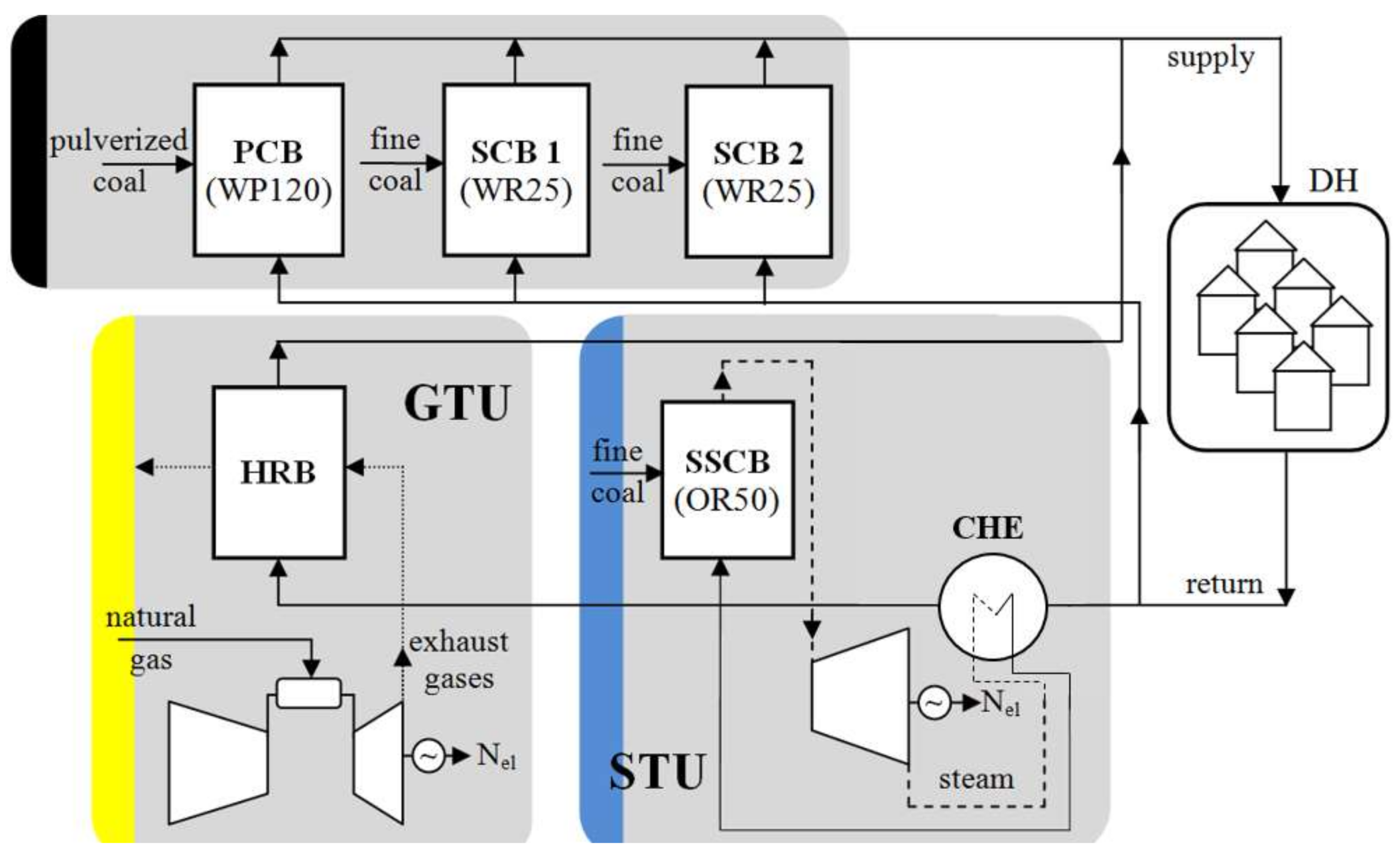
The investigation concerns assessment of available waste heat energy potential in a coal slag generated during hard coal combustion in a district heating grate boiler as well as proposals of its recovery. The research has been made on the basis of a steam boiler installed in the heat source of the municipal district heating system. The nominal capacity of the boiler fed with fine coal is 50 t/h of steam (45 MW thermal power). The considered plant is a heat source for high temperature municipal district heating system with the maximum demand for heat reaching 185 MW. The hot water of nominal pressure = 1.6 MPa and nominal (maximum) supply temperature = 150 °C is a heat carrier in the system. The plant consists of the following heat generating units, as shown in Figure 1:
- high efficient cogeneration unit based on a steam turbine STU supplied with hard coal stoker-fired steam boiler SSCB (labelled as OR50), examined for slag heat recovery,
- one pulverized hard coal-fired water boiler PCB (labelled as WP120) with the nominal heat capacity 125 MW,
- two hard coal stoker-fired water boilers SCB (labelled as WR25 no. 1 and no. 2) with the nominal heat capacity 33 MW each,
- a high-efficiency cogeneration unit based on a gas turbine unit GTU fired with natural gas of a nominal electric capacity 7.4 MW and integrated with a heat recovery boiler HRB of a nominal heat capacity 14.7 MW.
The simplified layout of stoker-fired boiler considered as a slag source is presented in the Figure 2. The output slag is a blend of coal slag formed on the grate furnace during combustion and fly ashes captured during dedusting processes. Ashes are reversed to the water slag trap. Slag and ash mixture is being cooled in the water and then carried out by set of belt conveyors for further treatment or disposal by landfilling.
3. Problem Formulation, Methods and Input Data
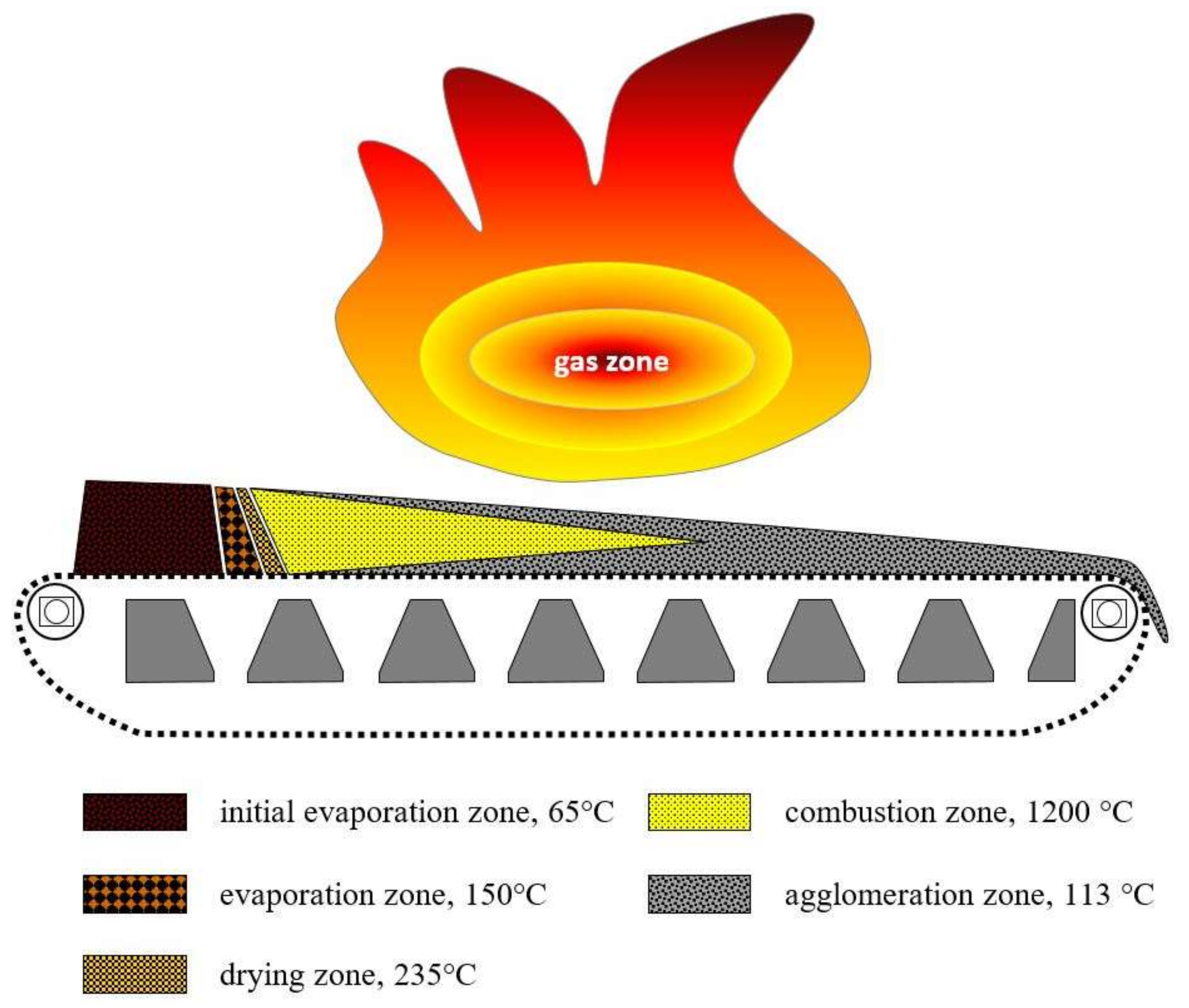
The combustion process of hard coal in a stoker-boiler is deeply connected with a grate furnace as a key component of the boiler. The slag is formed in the furnace where the layer of fine coal changes smoothly into slag during combustion. The slag formation process takes place already from the beginning part of the furnace where fine coal is fed through the feeding hopper. The layer thickness of the coal results from expected boiler capacity during operation. The slag volume, temperature and distribution on the grate results from the boiler load. The temperature of the slag at the end part of the grate determines the waste energy potential.
The solid material distribution in the furnace was observed during the research and the exemplary situation is shown in the Figure 3. It presents combusting zones for the case of a 50% load boiler operation. The combustion zone, with the highest temperature reaching 1200 °C, ends up in the middle part of the grate. In this case, the back part of the grate is covered by the agglomerating slag with a temperature reduced to 120–110 °C.
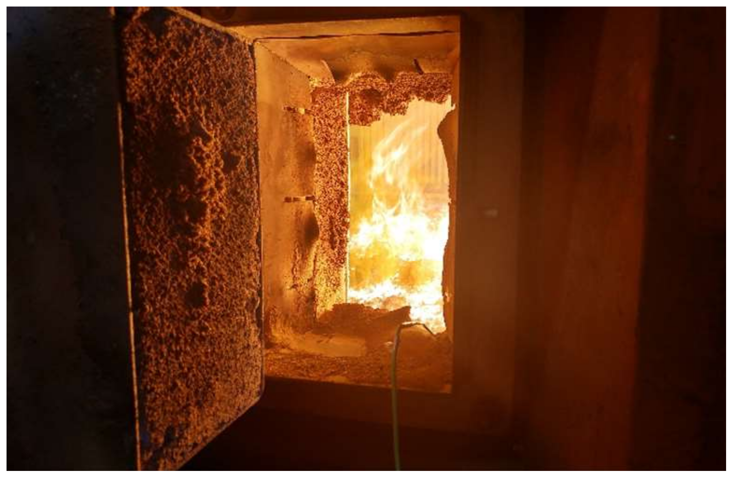
The middle part of the boiler with combusting coal on a grate is presented in the Figure 4. The picture has been taken through the inspection door of the boiler indicated in the Figure 2 and the gas area with flames can be easily recognized as well as the layer of coal combusted on the grate. The length of that zone is a direct reflection of the boiler load. In case of district heating boilers, the load results from the operation mode which depends on what is the boiler configuration in the plant. For the optimal sized boilers operated in a base of a load duration curve, the output capacity is usually close to nominal during the whole year time. In other configuration cases the capacity can be modulated and thus the temperature and volume of the output slag can change significantly.
The difference between the slag properties in case of two different loads of the same analyzed boiler can be noticed on the pictures presented in the Figure 5. Opening the back inspection door of the boiler operated with maximum load enabled to record combusting zone occurred even at the discharge part of the grate (Figure 5a). During the research observation, the combusting coal was even noticed falling down to the slag water trap. In case of decreased capacity, mainly during off-season operation, the combusting zone is shortening what can be confirmed by the Figure 5b.
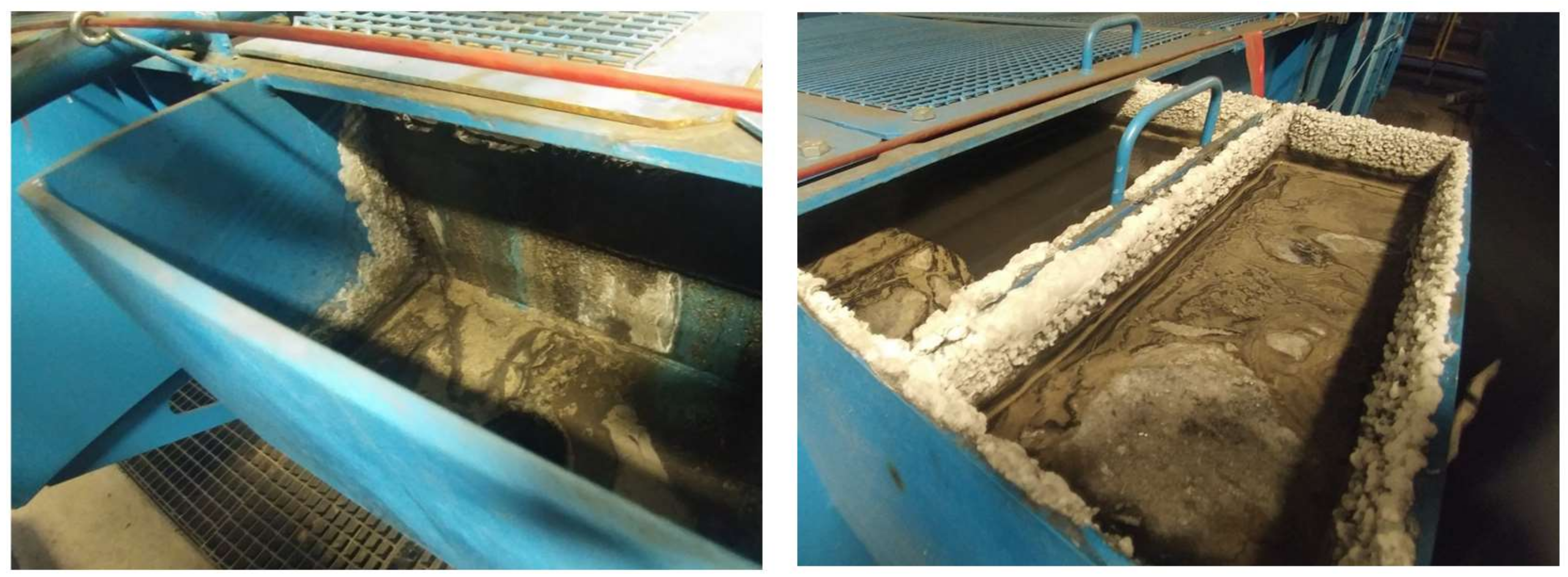
The idea of recovering waste heat from the slag is not only energy-saving in itself but also cools the water in the deslagger tub for the sake of minimizing tribocorrosion effects. In the analyzed case, triborrocion is the more intensive and problematic the higher temperatures of water in the tub. Figure 6 presents salt efflorences and corrosion traces on the walls of deslagger water trap after one month of operation in high temperature conditions.
In order to estimate waste energy potential of the slag leaving the boiler it was necessary to evaluate the volume of the slag as well as its temperature. The chosen physical and chemical properties of the slag and coal supplying the boiler also needed to be investigated.
In the beginning of the research procedure, the properties of hard coal were determined weekly. The results of the measurements are then used for further evaluation of waste energy potential of the coal slag. Chosen exemplary values are shown in the Table 1.
The slag available for energy recovery directed to the water trap is in fact a mixture of slag from the grate and fly ashes from the dedusting facility. Its properties have been measured and the exemplary data is presented in Table 2.
The temperature of the slag leaving the boiler ts has been measured and recorded online by the measurement set equipped with K-type (NiCr-NiAl) thermocouples (TP-204K-1b-1200-2,0). In order to determine slag volume, it was necessary to measure the fuel flow supplying the boiler. The measurement has been done automatically by the weighting system installed in the feeding hoppers of the boiler and recorded by SCADA system Pro2000.
The slag volume has been evaluated in the function of the coal quantity supplying the furnace, according to Formula (1):
where:
- —unitary slag volume, kg/kg of coal
- —coefficient of ash contraction in coal, assumed as 0.9
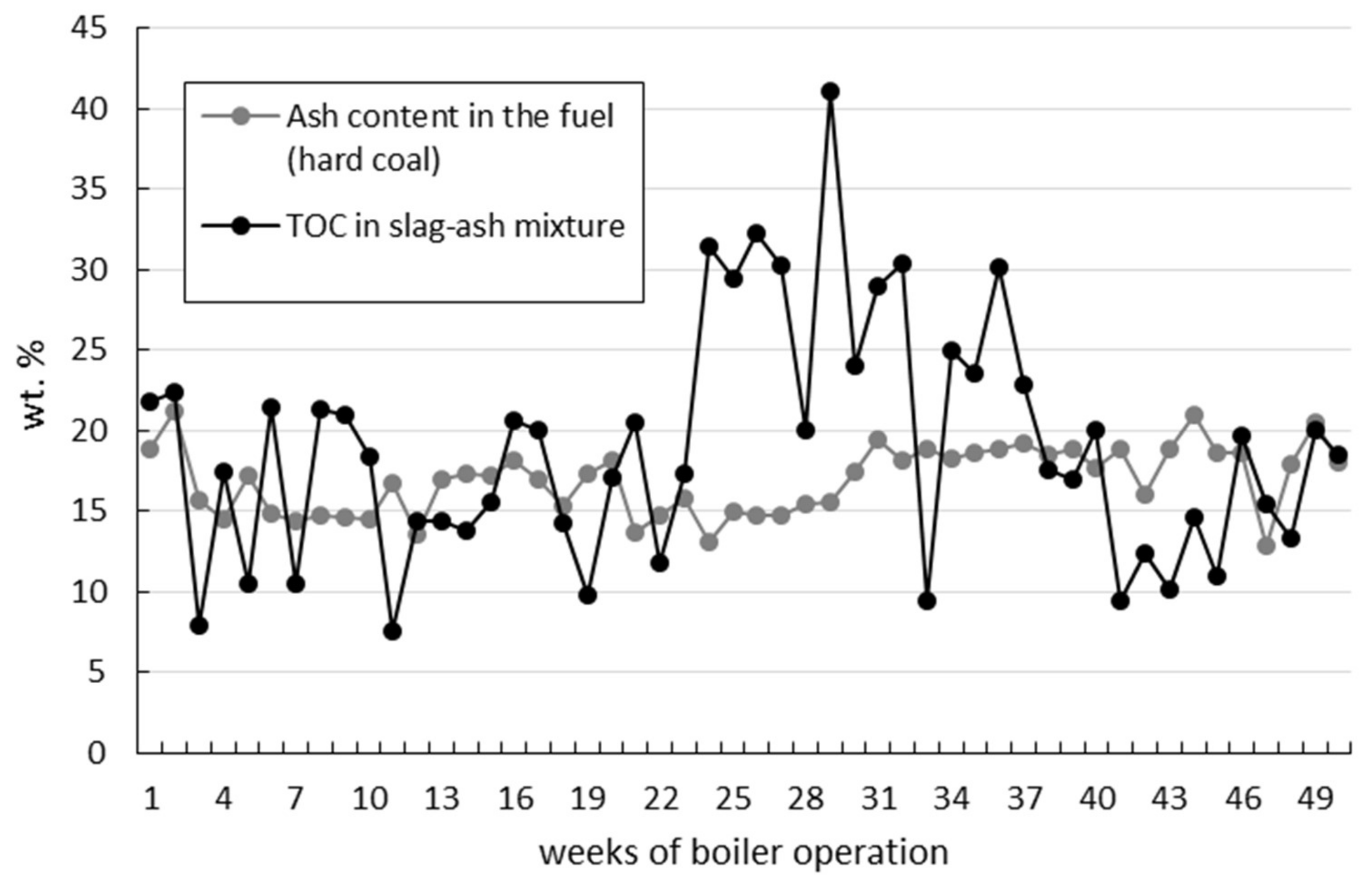
- —ash content in coal, wt.%
- —total organic carbon of slag-ash mixture, wt.%
Figure 7 presents results of and weekly measurements taken during the one year of boiler operation, while Figure 8 contains unitary slag volume determined from Formula (1).
It can be observed that total organic carbon in the output slag is significant higher during summer time, where boiler is operated with a lower load, which makes the combustion process less effective.
The content in the slag is the matter of chemical and physical enthalpy of the slag, according to Formula (2):
where:
- —enthalpy flux of the slag, kW
- —physical enthalpy flux of the slag, kW
- —chemical enthalpy flux of the slag, kW
For the purpose of the research, it has been assumed that only physical enthalpy of the slag is the subject of the recovery, thus:
where:
- —slag flux, kg/s
- —specific physical enthalpy of the slag, kJ/kg
- —slag temperature, °C.
The annual quantity of waste energy in the slag can be derived basing on Formula (4):
It has been assumed that the energy that it is possible to recover is accumulated in the water inside the deslagger tub which can be calculated according to the energy balance presented in Figure 9 and in Formula (5).
where:
- —heat flux available for recovery, kW
- —physical enthalpy flux of the slag, kW
- —physical enthalpy of the slag leaving deslagger, kW
- —physical enthalpy of the water lost with the slag, kW
- —heat energy losses, kW, assumed as 2% of
- —physical enthalpy of the refill water, kW
The quantity of waste energy annually available for recovery can be derived from Formula (6):
4. Results and Discussion
As the result of assumed method and presented input data the slag waste energy flux and its part available for the recovery have been derived. The output capacity distribution of the analyzed boiler and the temperature of the slag are presented in Figure 10.
The decrease of the boiler thermal output after around 5000 h of operation, shown in the Figure 9, is the result of boiler operation at the base of the heat load duration curve. In the analyzed district heating plant, the heat demand decreases significantly during the summer time, which requires a reduction of the boiler thermal output. During the off season periods, the heat demand of district heating system is the result only of domestic hot water needs. It should also be stated here that the total annual time of boiler operation does not exceed 8200 h due to the maintenance works and other necessary standstills. The content of Figure 10 confirms strict correlation between load of the boiler and slag temperature which remains in line with previous discussion presented in the problem formulation section of the paper.
The annual distribution curve of enthalpy flux of the slag is presented in Figure 11—as the result of proposed evaluation procedure. It can be seen that the highest values of waste energy flux occurs during maximum load of the boiler and equals to 508 kW. The value is relatively small, compared to maximum thermal output of the boiler, which is around 45 MW. It needs to be noticed here that off-season period has much less potential of slag waste energy, due to the slower temperatures of the slag and decreased slag volume.
The annual quantity of waste energy available in the slag, derived from Formula (4) equals 1,969,451 kWh (7090 GJ). This amount can be gained by means of an appropriate recovery system. The authors propose the solution based on a high temperature heat pump used for transferring heat from water in the deslagger to district heating network. The heat sink of the heat pump is the return pipe of the DH system with temperatures from 55 °C to 70 °C, according to the ambient temperatures and DH heat demand.
The idea of using heat pumps for heat recovery purposes is well-known solution, according to the literature. High temperature heat pump applications are reported to be efficient solutions, particularly in industrial cases. During simulations, Yu at al. proved that high temperature heat pumps (HTHP) are capable to produce heat at the temperature of 120 °C with good performance [28]. Wu at al. explained that in some industrial cases the on-site testing the HTHP system could be reliably operated to heat the liquid temperature up to 95 °C with an average system coefficient of performance COP of 4.2 during the entire heating process [29]. Yu et al. showed that under the experimental conditions of the inlet water temperature of evaporator at 50–70 °C, the outlet water temperature of condenser could reach 80–110 °C [30]. Although Zhang et al. reported even 135 °C on condensing unit [31]. Experimental and numerical investigations of a new high temperature heat pump for industrial heat recovery using water as refrigerant was performed by Camoun at al. and their experimental investigations of this heat pump were carried out in the condensing temperature range of 130–140 °C. Economic analysis indicated that the HTHP system could save about 47% of the operating cost in comparison to the traditional steam heating [32].
5. Proposal of Technical Solution for Slag Energy Recovery
On the basis of the research and observations of current slag treatment system of the analyzed boiler, heat pump system was proposed for slag energy recovery. The heat source of the pump is in the deslagger tub filled with the water and the heat sink is the return pipe of the district heating network. The target configuration of the district heating plant equipped with heat pump (HP) is presented in Figure 12.
A detailed diagram of the proposed system is shown in Figure 13. It consists of a heat source equipped with heat exchanger HE submerged in the deslagger water tub and low loss header. The header separates the high temperature heat pump HP from polluted tub water. At the high temperature side, a heat pump is connected to the heat sink. The heat sink is the return pipe of the district heating system.
In order to enable the waste heat to be obtained from the deslagger water tub, the following two proposals of modification of the tub unit has been proposed and assumed to be technically possible to apply:
- direct heat recovery in the existing slag trap,
- first proposal extended by installing a worm conveyor tube covered by a heat exchanger coil.
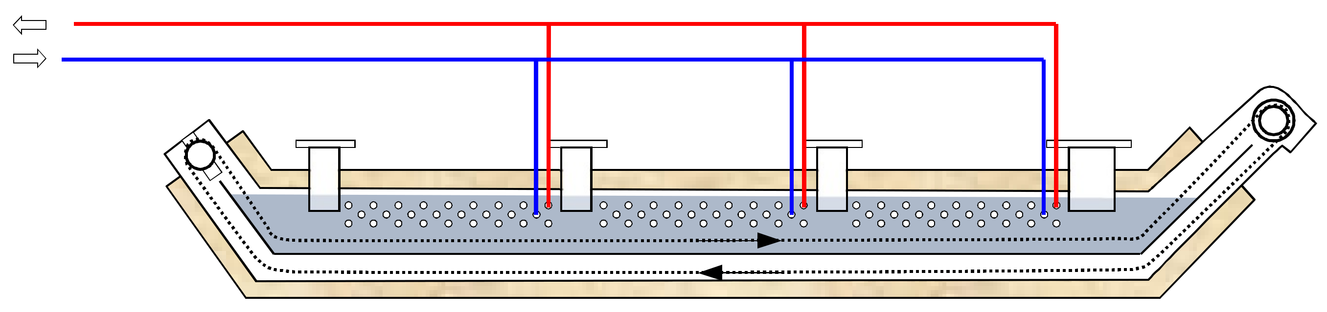
Both ideas of heat recovery in the slag trap have been presented in Figure 14 and Figure 15. The first proposal given by the author, based on a direct heat recovery from a slag trap, requires simple modification of slag trap water chute. The proposal assumes installing water-water heat exchanger inside the trap and thermal insulation of the trap. As it can be seen in Figure 14, heat exchanger pipes are placed in the upper liquid layer, where the water has highest temperature. Optionally, circulating pumps for mixing water in the top layer for better heat exchange can be applied.
The second idea, presented in Figure 15, contains the same improvements on the first proposal. However, it is extended and additionally results from an approach to solve the problem of low heat conductivity of the slag, which is usualyl in the form of different sized coarse solid rock-like particles (of equivalent diameter in the range of 0.01–0.5 m). The principle of this concepts is based on crushing and homogenizing of the slag by a worm conveyor tube covered by a heat exchanger coil. In this waste heat recovery system, hot water from the exchanger is introduced counter-current to the slag discharge direction, which increases water even more. The slag goes to the opposite end of the trap which extends its contact with the cooling water. The system can produce steam, but requires better construction materials and a pumping facility.
5.1. Energy Performance of the Slag Waste Heat Recovery System
Annual distribution curve of heat flux recovered from the slag due to the heat pump system is presented in Figure 16—as the result of proposed evaluation procedure.
Derived heat flux is in the range of 58.8–88.0% of the waste energy potential of the slag. The annual quantity of waste energy recovered from the slag derived from Formula (6) equals to 1,700,600 kWh (6122 GJ).
It should be mentioned in this section of the paper that application of high temperature heat pump for slag waste energy recovery requires considering specific temperatures conditions in the deslagger on one side and heat pump operating cycle on the other side.
In the deslagger tub there are water temperature fluctuations depending on the efficiency of the boiler. The temperature may drop below 50 °C and also reach 100 °C. The temperature of the water in the tub has a big influence on the durability of the entire slag trap. From the point of view of technology, it is advantageous to keep the temperature in the bathtub as low as possible.
On the other hand, we have temperatures from 55 °C to 70 °C at the return pipe from district heating system. This means that it is not possible to recover the heat directly from water in the slag tub. In addition, in case of failure of such a direct heat exchanger, there is a danger of district heating water contamination. Therefore, a solution based on a heat pump is proposed, which on the one hand will lower the temperature in the slag tub and stabilize it, on the other hand it will be able to heat the district heating return water even when its temperature is 70 °C. For this purpose, the refrigerant in the heat pump should be able to reach temperatures above 70 °C during condensation. A good and economical solution is to use 1,1,1,2-Tetrafluoroetan (R134a, also known as HFC-R134a) with 1430 of global warming potentials (GWP). The R134a allows us to obtain 78 °C in a condenser, while maintaining the temperature of the bottom source at 45 °C (Figure 17). The heat pump operated with R134a according to the cycle presented in Figure 17 can reach a COP of up to 6.6 taking into account only thermodynamic cycle performance.
Due to the F-Gas Regulation (EU) No 517/2014 of April 16, which lowers the maximum GWP limits (to 2 500 by the year of 2020 and 150 by the year of 2022), the alternative for the proposed system may be a more expensive refrigerant 2,3,3,3-Tetrafluoropropene (R1234yf, also known as HFO-1234yf), with GWP less than 7.
5.2. Energy Performance of the Waste Heat Recovery System
On the basis of presented discussion the high temperature heat pump operated with R134a working medium was sized regarding the heat flux available for recovery. The main design parameters of the pump are presented in Table 3.
The annual operation parameters have been derived regarding annual distribution curve of recovered heat available for recovery (Figure 16) and design parameters of the heat pump, as follows:
- annual operation time of the heat pump: = 3115 h,
- heat recovered from the deslagger: = 1,700,600 kWh (6122 GJ),
- heat supplied into the return pipe of district heating system: = 2,270,582 kWh (8174 GJ),
- electricity consumed by the heat pump: = 616,390 kWh.
5.3. Economic Evaluation
The simple economic pre-feasibility evaluation of the proposed waste heat recovery system was carried out on the basis on the annual cash flows generated by the recovery system [33]. The design parameters of the selected heat pump along with technical assumption of the recovery system allowed us to estimate total outlays of the project . Next, derived energy quantities including effects and inputs were used to calculate annual cash flows. For the sake of rough calculations, the authors took into account the recovered heat supplied into the district heating system (positive effect) and electricity consumption of the heat pump (negative effect). To calculate the annual profits and costs , heat and electricity prices were also assumed as follows:
- price of heat generated in the analyzed plant: = 6 €/GJ,
- electricity price consumed by the heat pump: = 50 €/MWh.
It should be stated here that electricity used for driving the heat pump is generated onsite—in the cogeneration units installed in the DH plant so the price is attractive compared to price of electricity offered by distribution companies.
The summary economic effects of proposed solution for proposed heat recovery are shown in Table 4.
6. Conclusions
The direct result of the presented research is the estimation of a waste heat recovery from the coal slag generated in grate boiler supplied with hard coal. The waste heat available for recovering derived during the analysis is relatively low and does not exceed 1% of maximum thermal output of the boiler, which is reflected in the considerations presented in [9].
Regardless of the low share of energy contained in this slag in the total energy balance of the furnaces, the authors decided that it is still worth emphasizing the proposal of a technically possible and feasible application for waste heat recovery from the slag. The proposed modifications are focused on high temperature heat pump connected to the deslagging system as a strategic device within the heating plant infrastructure. The failure-free operation of the slag trap is critical for the system and the observations show that in the majority of cases, the customers are not satisfied with the long-term used deslagging solutions. The proposed modification may then be applied in case of retrofitting old, defective traps.
On the basis of the conducted analysis, the following final conclusions can be drawn.
- High temperature of the slag generated in the boiler can be a challenge for developing heat recovery system.
- Waste energy potential of the slag produced in stoker-boilers fired with hard coal has relatively low share in boiler energy balance.
- Recovering the heat from the slag not only improves the energy efficiency of the district heating system but, due to the reduction of the temperature of water in the slag tub, limits the tribocorrosion phenomena in the deslagger.
- Applying a heat pump for energy recovery from the slag can be more feasible if electricity is available onsite from a production facility (cogeneration units in the analyzed case).
- The proposal of heat recovery systems from low temperature slag is a technical and economic challenge but can be an economically justified solution in certain circumstances.
- Slag energy recovery facilities should be applied in line with old traps replacement to improve economic feasibility of the recovery.
Acknowledgments
The authors would like to thank the ECO SA—Heat Engineering Company engineers for the cooperation and for the access to operational data of heat generating district heating plant. The authors also gratefully acknowledge the possibility of using the design data of analyzed unites to the ECO SA company.
Author Contributions
Maciej Masiukiewicz and Mariusz Tańczuk conceived and designed the experiments and analysis; Maciej Masiukiewicz and Mariusz Tańczuk provided the analysis tools and analyzed the data; Robert Junga performed the measurements of the properties of the hard coal and slag; Stanisław Anweiler and Mariusz Tańczuk wrote the paper.
Conflicts of Interest
The authors declare no conflict of interest.
Abbreviations
| coefficient of ash contraction in coal | |
| ash content in coal, wt.% | |
| specific heat of the slag, kJ/kgK | |
| electricity consumption of the heat pump, kWh | |
| slag flux, kg/s | |
| specific physical enthalpy of the slag, kJ/kg | |
| chemical enthalpy flux of the slag, kW | |
| physical enthalpy of the water lost with the slag, kW | |
| physical enthalpy of the slag leaving deslagger, kW | |
| physical enthalpy of the refill water, kW | |
| physical enthalpy flux of the slag, kW | |
| enthalpy flux of the slag, kW | |
| k | thermal conductivity, W/mK |
| electric power output of cogeneration units, kW | |
| hot water nominal pressure, MPa | |
| output capacity distribution of the boiler, MW | |
| annual quantity of waste energy supplied to the district heating DH system, GJ | |
| annual quantity of waste energy recovered from the slag, GJ | |
| heat flux available for recovery, kW | |
| heat energy losses, kW | |
| annual quantity of waste energy in the slag, GJ | |
| waste energy flux, kW | |
| heating capacity, kW | |
| unitary slag volume, kg/kg of coal | |
| time, h | |
| annual operation time of heat pump, h | |
| total organic carbon, % | |
| total organic carbon of slag-ash mixture, wt.% | |
| temperature of DH return water, °C | |
| slag temperature, °C | |
| nominal (maximum) supply temperature, °C | |
| water temperature in the deslagger tub, °C | |
| CHE | condenser heat exchange unit |
| DH | district heating |
| GTU | gas turbine unit |
| HE | heat exchanger |
| HP | heat pump |
| HRB | heat recovery boiler |
| PCB | pulverized hard coal-fired water boiler |
| SCB | stocker coal boiler |
| SPB | simple payback time |
| SSCB | hard coal stoker-fired steam boiler |
| STU | steam turbine unit |
References
- Rose, L. (Ed.) Energy: Modern Energy Storage, Conversion, and Transmission in the 21st Century; Nova Science Publishers, Inc.: New York, NY, USA, 2013. [Google Scholar]
- Klemeš, J.J. (Ed.) Assessingand Measuring Environmental Impact and Sustainability; Butterworth-Heinemann: Oxford, UK, 2015. [Google Scholar]
- Duić, N.; Rosen, M.A. Sustainable development of energy systems. Energy Convers. Manag. 2014, 87, 1057–1062. [Google Scholar] [CrossRef]
- Sadek, D.M. Effect of cooling technique of blast furnace slag on the thermal behavior of solid cement bricks. J. Clean. Prod. 2014, 79, 134–141. [Google Scholar] [CrossRef]
- Wzorek, M.; Kozioł, M.; Ścierski, W. Emission characteristics of granulated fuel produced from sewage sludge and coal slime. J. Air Waste Manag. Assoc. 2010, 60, 1487–1493. [Google Scholar] [CrossRef] [PubMed]
- Stijepovic, M.Z.; Linke, P. Optimal waste heat recovery and reuse in industrial zones. Energy 2011, 36, 4019–4031. [Google Scholar]
- Chae, S.H.; Kim, S.H.; Yoon, S.G.; Park, S. Optimization of a waste heat utilization network in an eco-industrial park. Appl. Energy 2010, 87, 1978–1988. [Google Scholar] [CrossRef]
- Nemet, A.; Klemeš, J.J.; Kravanja, Z. Optimising entire lifetime economy of heat exchanger networks. Energy 2013, 57, 222–235. [Google Scholar] [CrossRef]
- Ma, G.Y.; Cai, J.J.; Zeng, W.W.; Dong, H. Analytical research on waste heat recovery and utilization of China’s iron & steel industry. Energy Procedia 2012, 14, 1022–1028. [Google Scholar]
- Szargut, J.; Ziębik, A.; Kozioł, J.; Kurpisz, K.; Majza, E. Industrial Waste Energy; WNT: Warsaw, Poland, 1993; (In Polish). ISBN 83-204-1626-4. [Google Scholar]
- Barati, M.; Esfahani, S.; Utigard, T.A. Energy recovery from high temperature slags. Energy 2011, 36, 5440–5449. [Google Scholar] [CrossRef]
- Bisio, G. Energy recovery from molten slag and exploitation of the recovered energy. Energy 1997, 22, 501–509. [Google Scholar] [CrossRef]
- Mills, K.C. Heat Transfer and Thermal Conductivity of Coal Slags. In Mineral Matter and Ash in Coal; ACS Symposium Series 301; Vorres, K.S., Ed.; American Chemical Society: Washington, DC, USA, 1986; pp. 256–276. [Google Scholar]
- Rezaei, H.R.; Gupta, R.P.; Bryant, G.W.; Hart, J.T.; Liu, G.S.; Bailey, C.W.; Wall, T.F.; Miyamae, S.; Makino, K.K.; Endo, Y. Thermal conductivity of coal ash and slags and models used. Fuel 2000, 79, 1697–1710. [Google Scholar] [CrossRef]
- Henry, P.; Takadoum, J.; Berçot, P. Tribocorrosion of 316L stainless steel and TA6V4 alloy in H2SO4 media. Corros. Sci. 2009, 51, 1308–1314. [Google Scholar] [CrossRef]
- Jiang, J.; Stack, M.M.; Neville, A. Modelling the tribo-corrosion interaction in aqueous sliding conditions. Tribol. Int. 2002, 35, 669–679. [Google Scholar] [CrossRef]
- Mischler, S. Triboelectrochemical techniques and interpretation methods in tribocorrosion: A comparative evaluation. Tribol. Int. 2008, 41, 573–583. [Google Scholar] [CrossRef]
- Mi, X.; Cai, Z.B.; Xiong, X.M.; Qian, H.; Tang, L.C.; Xie, Y.C.; Peng, J.F.; Zhu, M.H. Investigation on fretting wear behavior of 690 alloy in water under various temperatures. Tribol. Int. 2016, 100, 400–409. [Google Scholar] [CrossRef]
- Diomidis, N.; Mischler, S. Third body effects on friction and wear during fretting of steel contacts. Tribol. Int. 2011, 44, 1452–1460. [Google Scholar] [CrossRef]
- Hasan, B.O.; Sadek, S.A. The effect of temperature and hydrodynamics on carbon steel corrosion and its inhibition in oxygenated acid–salt solution. J. Ind. Eng. Chem. 2014, 20, 297–307. [Google Scholar] [CrossRef]
- Wang, Z.H.; Lu, Y.H.; Li, J.; Shoji, T. Effect of pH value on the fretting wear behavior of Inconel 690 alloy. Tribol. Int. 2016, 95, 162–169. [Google Scholar] [CrossRef]
- López-Ortega, A.; Bayón, R.; Arana, J.L.; Arredondo, A.; Igartua, A. Influence of temperature on the corrosion and tribocorrosion behaviour of High-Strength Low-Alloy steels used in offshore applications. Tribol. Int. 2018, in press. [Google Scholar]
- Sun, Y.; Shen, H.; Wang, H.; Wang, X.; Zhang, Z. Experimental investigation and modeling of cooling processes of high temperature slags. Energy 2014, 76, 761–767. [Google Scholar] [CrossRef]
- Trashorras, A.J.G.; Álvarez, E.Á.; González, J.L.R.; Cuesta, J.M.S.; Bernat, J.X. Design and evaluation of a heat recuperator for steel slags. Appl. Therm. Eng. 2013, 56, 11–17. [Google Scholar] [CrossRef]
- Ortega-Fernández, I.; Calvet, N.; Gil, A.; Rodríguez-Aseguinolaza, J.; Faik, A.; D’Aguanno, B. Thermophysical characterization of a by-product from the steel industry to be used as a sustainable and low-cost thermal energy storage material. Energy 2015, 89, 601–609. [Google Scholar] [CrossRef]
- Zhang, H.; Wang, H.; Zhu, X.; Qiu, Y.J.; Li, K.; Chen, R.; Liao, Q. A review of waste heat recovery technologies towards molten slag in steel industry. Appl. Energy 2013, 112, 956–966. [Google Scholar] [CrossRef]
- Mills, K.C. Estimation of physicochemical properties of coal slags. In Mineral Matter and Ash in Coal; ACS Symposium Series 301; Vorres, K.S., Ed.; American Chemical Society: Washington, DC, USA, 1986; pp. 195–214. [Google Scholar]
- Yu, X.; Zhang, Y.; Kong, L.; Zhang, Y. Thermodynamic analysis and parameter estimation of a high-temperature industrial heat pump using a new binary mixture. Appl. Therm. Eng. 2018, 131, 715–723. [Google Scholar] [CrossRef]
- Wu, X.; Xing, Z.; He, Z.; Wang, X.; Chen, W. Performance evaluation of a capacity-regulated high temperature heat pump for waste heat recovery in dyeing industry. Appl. Therm. Eng. 2016, 93, 1193–1201. [Google Scholar] [CrossRef]
- Xiaohui, Y.; Yufeng, Z.; Na, D.; Chengmin, C.; Yan, Z. Experimental performance of high temperature heat pump with near-azeotropic refrigerant mixture. Energy Build. 2014, 78, 43–49. [Google Scholar] [CrossRef]
- Zhang, Y.; Zhang, Y.; Yu, X.; Guo, J.; Deng, N.; Dong, S.; He, Z.; Ma, X. Analysis of a high temperature heat pump using BY-5 as refrigerant. Appl. Therm. Eng. 2017, 127, 1461–1468. [Google Scholar] [CrossRef]
- Chamoun, M.; Rulliere, R.; Haberschill, P.; Peureux, J.L. Experimental and numerical investigations of a new high temperature heat pump for industrial heat recovery using water as refrigerant. Int. J. Refrig. 2014, 44, 177–188. [Google Scholar] [CrossRef]
- Tańczuk, M.; Skorek, J.; Bargiel, P. Energy and economic optimization of the repowering of coal-fired municipal district heating source by a gas turbine. Energy Convers. Manag. 2017, 149, 885–895. [Google Scholar] [CrossRef]
Figure 1.
Schematic diagram of the current configuration of the analyzed district heating (DH) plant with heat and electricity generation.
Figure 1.
Schematic diagram of the current configuration of the analyzed district heating (DH) plant with heat and electricity generation.

Figure 2.
Schematic layout of the stoker-boiler under investigation with a deslagger with tub fueled with water (water trap at the bottom).
Figure 2.
Schematic layout of the stoker-boiler under investigation with a deslagger with tub fueled with water (water trap at the bottom).
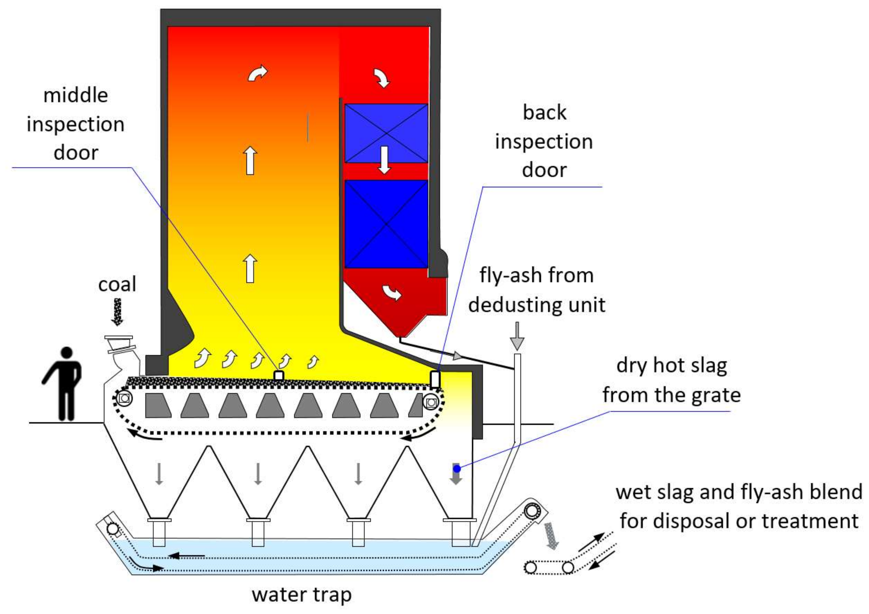
Figure 3.
The illustrative distribution of the temperature of coal and slag on the grate of a stoker-boiler.
Figure 3.
The illustrative distribution of the temperature of coal and slag on the grate of a stoker-boiler.

Figure 4.
The middle part of grate—view from the middle inspection door of the boiler.

Figure 5.
The end section of the grate with discharge of the slag to the slag trap—view from the back inspection door of the boiler: (a) operation with full load, (b) operation with 30% of load during off-season period.
Figure 5.
The end section of the grate with discharge of the slag to the slag trap—view from the back inspection door of the boiler: (a) operation with full load, (b) operation with 30% of load during off-season period.
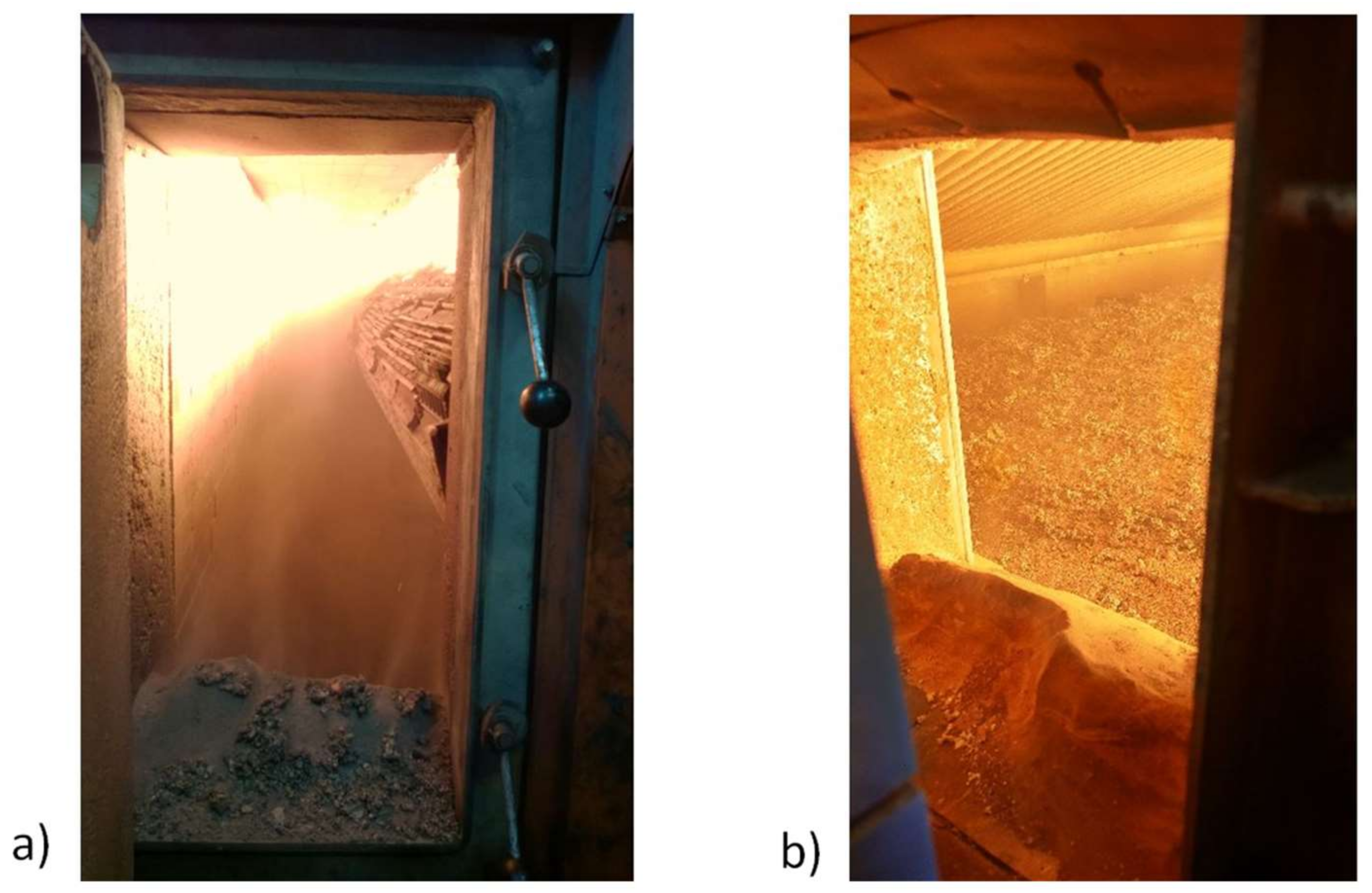
Figure 6.
Tribocorrosion traces on the walls of deslagger water trap occurred during operation with high temperature water in the tub.
Figure 6.
Tribocorrosion traces on the walls of deslagger water trap occurred during operation with high temperature water in the tub.

Figure 7.
Ash content of the fuel and total organic carbon (TOC) in slag-ash mixture measured weekly.
Figure 7.
Ash content of the fuel and total organic carbon (TOC) in slag-ash mixture measured weekly.

Figure 8.
Unitary slag volume .
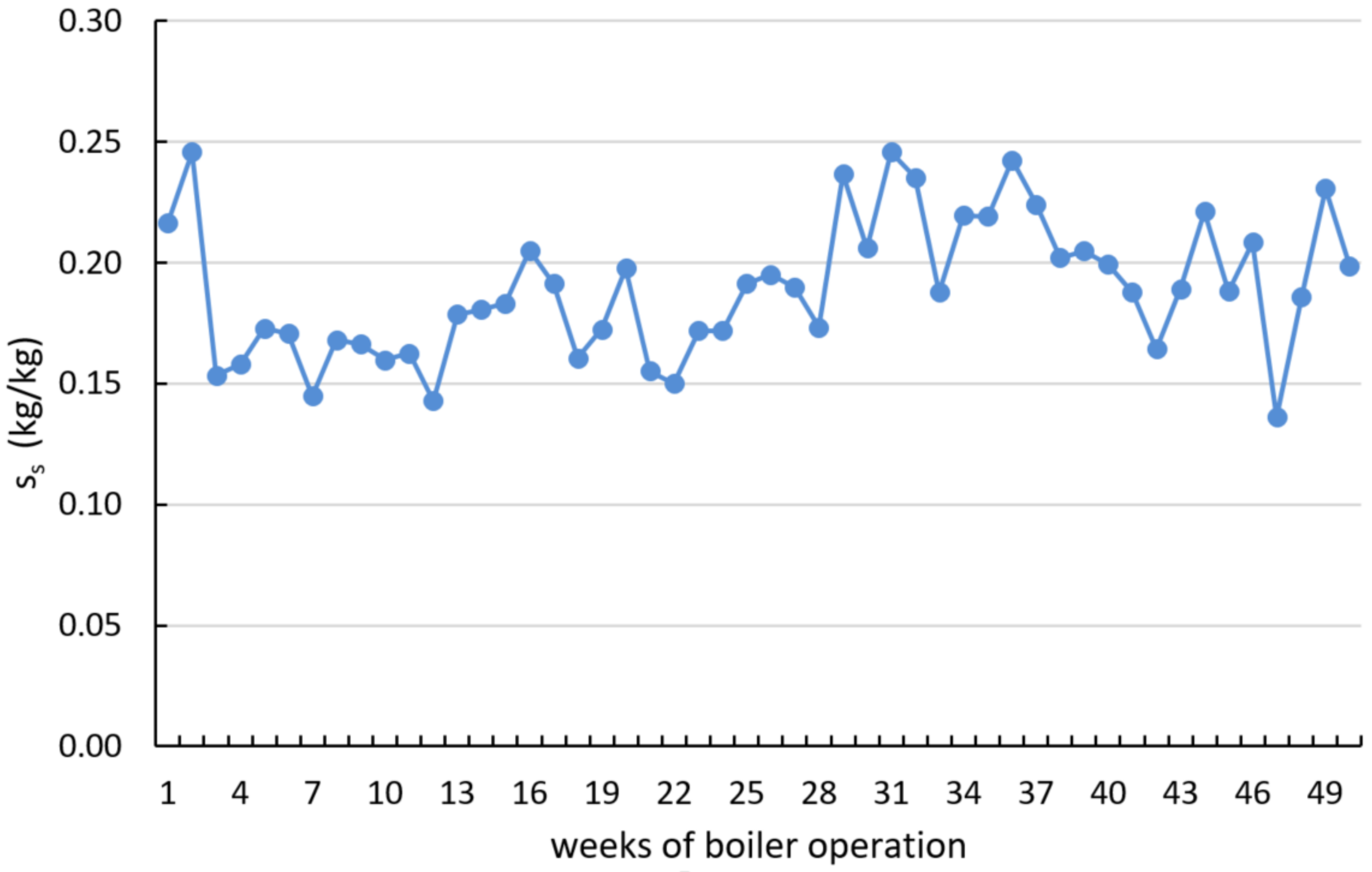
Figure 9.
Energy balance of the deslagging device of the boiler.
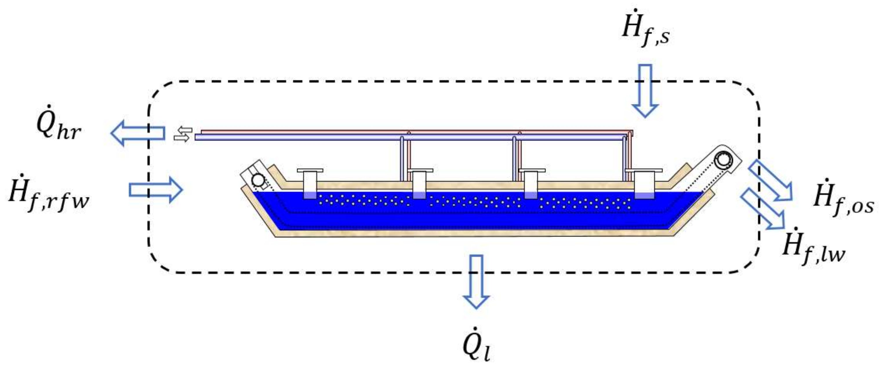
Figure 10.
Annual distribution curve of boiler output capacity and slag temperature ts at the end section of the grate.
Figure 10.
Annual distribution curve of boiler output capacity and slag temperature ts at the end section of the grate.
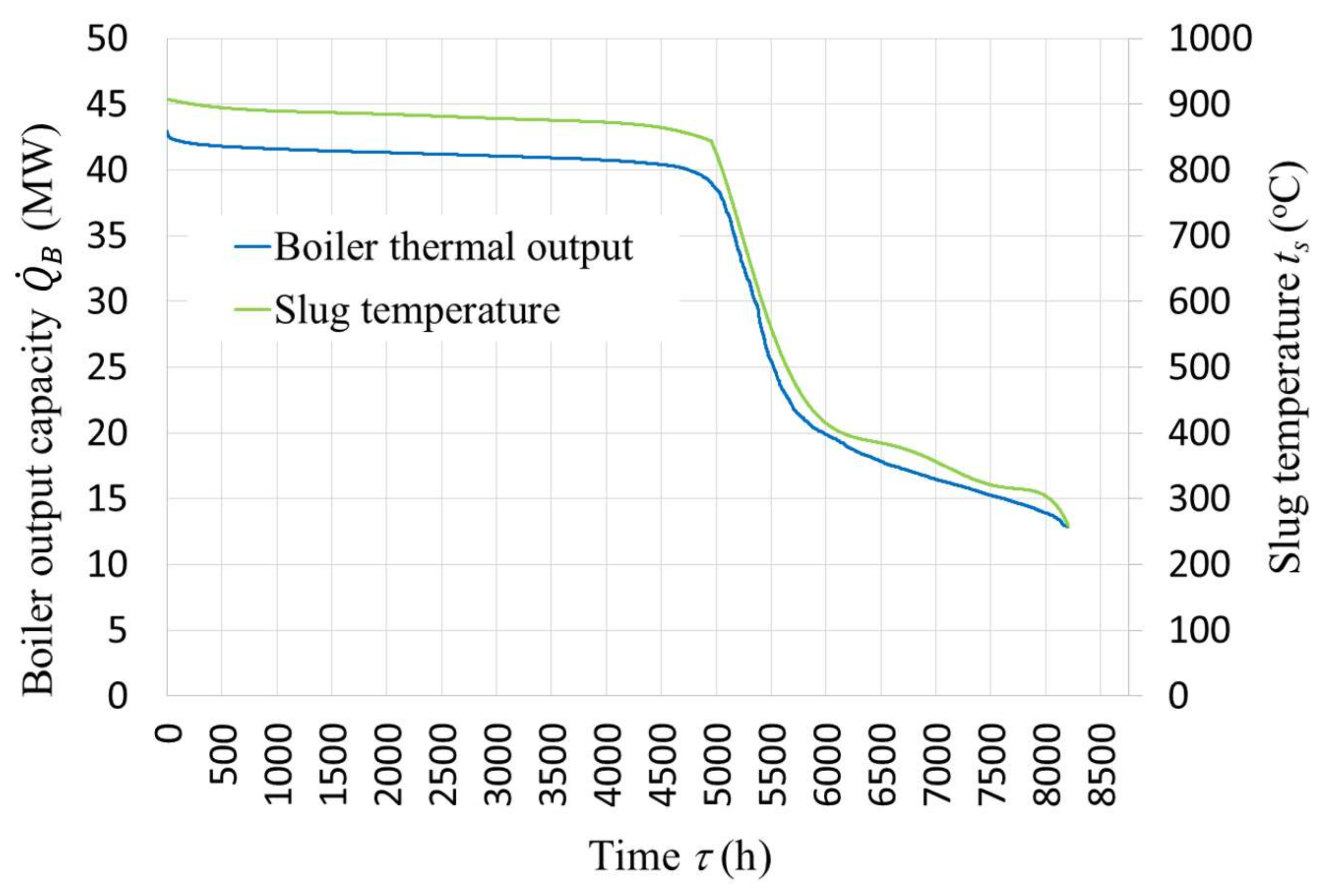
Figure 11.
Annual distribution curve of enthalpy flux of the analyzed slag.
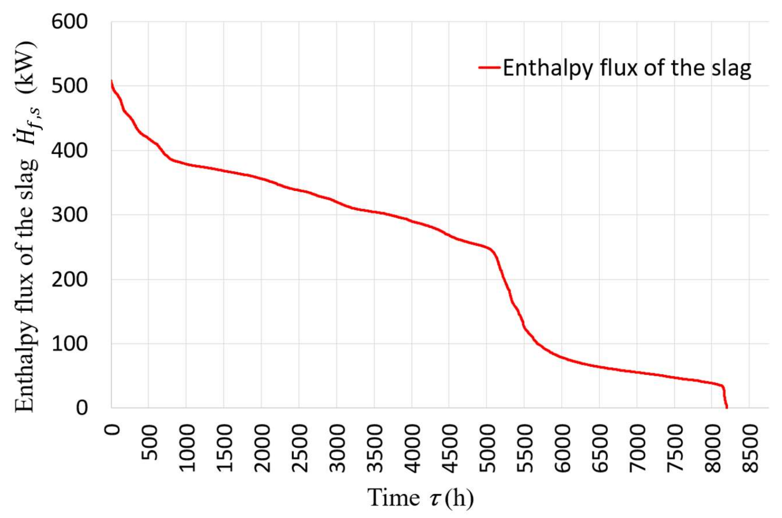
Figure 12.
Schematic diagram of the proposed configuration of analyzed DH plant retrofitted with heat pump (HP) system recovering heat from coal stoker-fired steam boiler (SSCB) slag.
Figure 12.
Schematic diagram of the proposed configuration of analyzed DH plant retrofitted with heat pump (HP) system recovering heat from coal stoker-fired steam boiler (SSCB) slag.

Figure 13.
Detailed schematic diagram of the proposed slag heat recovery system based on a high temperature heat pump HP.
Figure 13.
Detailed schematic diagram of the proposed slag heat recovery system based on a high temperature heat pump HP.
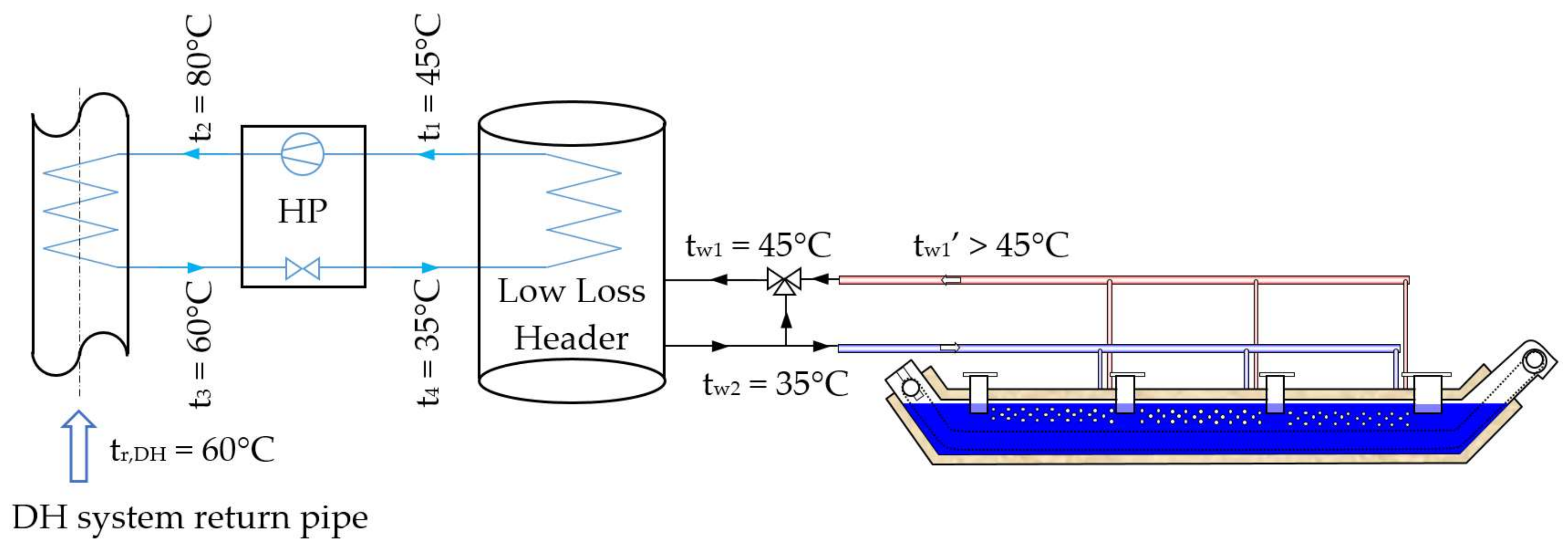
Figure 14.
A direct slag waste heat recovery proposal.

Figure 15.
A direct slag waste heat recovery extended by crushing and homogenizing of the slag in a worm conveyor tube covered by the additional heat exchanger coil.
Figure 15.
A direct slag waste heat recovery extended by crushing and homogenizing of the slag in a worm conveyor tube covered by the additional heat exchanger coil.
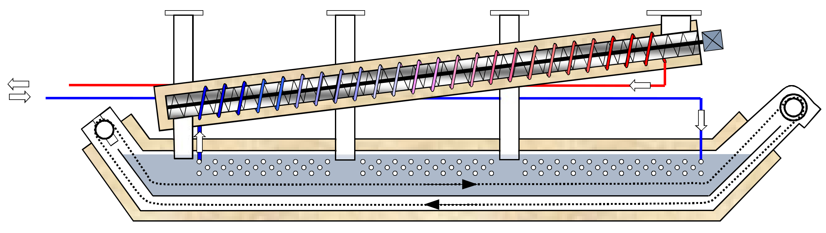
Figure 16.
Annual distribution curve of enthalpy flux of the analyzed slag.

Figure 17.
1,1,1,2-Tetrafluoroetan (HFC-134a) cycle of proposed high temperature heat pump presented on p-H diagram.
Figure 17.
1,1,1,2-Tetrafluoroetan (HFC-134a) cycle of proposed high temperature heat pump presented on p-H diagram.


Table 1.
Properties of hard coal used in the tested steam boiler.
| No. | Property | Unit | Value * | Testing Standard |
|---|---|---|---|---|
| 1 | Moisture content | wt.% | 10.5 | PN—80/G-04511 |
| 2 | Ash content | wt.% | 14.9 | Accredited testing procedure |
| 3 | Carbon content | wt.% | 62.83 | PN-G-04571:1998 |
| 4 | Hydrogen content | wt.% | 3.31 | ISO/TS 12902:2007 |
| 5 | Nitrogen content | wt.% | 1.10 | ISO/TS 12902:2007 |
| 6 | Sulphur content | wt.% | 0.40 | PN-ISO 351:1999 |
| 7 | Lower Heating Value | MJ kg−1 | 23.668 | Calculated |
| 8 | Higher Heating Value | MJ kg−1 | 27.185 | PN-81/G-04513 |
* As received.
Table 2.
Properties of the mixed slag and fly ash from the grate boiler.
| No. | Property | Unit | Value * | Testing Standard |
|---|---|---|---|---|
| 1 | Moisture content | wt.% | 31.0 | Accredited testing procedure |
| 2 | TOC | wt.% | 23.33 | Accredited testing procedure |
| 3 | Carbon content | wt.% | 15.3 | Accredited testing procedure |
| 4 | Size distribution: | wt.% | - | - |
| 4a | >10 | wt.% | 45.8 | - |
| 4b | 10 ÷ 5 | wt.% | 17.6 | - |
| 4c | 5 ÷ 3 | wt.% | 8.7 | - |
| 4d | 3 ÷ 1 | wt.% | 13.6 | - |
| 4e | 1 ÷ 0.5 | wt.% | 6.2 | - |
| 4f | <0.5 | wt.% | 8.1 | - |
* As received.
Table 3.
Main design parameters of the selected heat pump.
| Performance Information | Value |
|---|---|
| Heating capacity | 729 kW |
| Heating efficiency (coefficient of performance—COP) * | 3.69 kW/kW |
| Cooling capacity | 546 kW |
| Unit power input | 198 kW |
| Leaving temperature (evaporator) | 35 °C |
| Supply temperature (evaporator) | 45 °C |
| Leaving temperature (condenser) | 80 °C |
| Supply temperature (condenser) | 60 °C |
* Real COP, lower than theoretical COP = 6.6, due to the efficiencies of the particular components of designed heat pump.
Table 4.
Economic effects of heat recovery from slag
| Parameter | Value |
|---|---|
| Total investment cost | 130,000 € |
| Annual incomes | 49,044 € |
| Annual costs | 30,820 € |
| Simple payback time SPB | 7.1 years |
© 2018 by the authors. Licensee MDPI, Basel, Switzerland. This article is an open access article distributed under the terms and conditions of the Creative Commons Attribution (CC BY) license (http://creativecommons.org/licenses/by/4.0/).
Share and Cite
MDPI and ACS Style
Tańczuk, M.; Masiukiewicz, M.; Anweiler, S.; Junga, R. Technical Aspects and Energy Effects of Waste Heat Recovery from District Heating Boiler Slag. Energies 2018, 11, 796. https://doi.org/10.3390/en11040796
AMA Style
Tańczuk M, Masiukiewicz M, Anweiler S, Junga R. Technical Aspects and Energy Effects of Waste Heat Recovery from District Heating Boiler Slag. Energies. 2018; 11(4):796. https://doi.org/10.3390/en11040796
Chicago/Turabian StyleTańczuk, Mariusz, Maciej Masiukiewicz, Stanisław Anweiler, and Robert Junga. 2018. "Technical Aspects and Energy Effects of Waste Heat Recovery from District Heating Boiler Slag" Energies 11, no. 4: 796. https://doi.org/10.3390/en11040796
Note that from the first issue of 2016, this journal uses article numbers instead of page numbers. See further details here.