Application of a Continuous Particle Swarm Optimization (CPSO) for the Optimal Coordination of Overcurrent Relays Considering a Penalty Method


Abstract
:1. Introduction
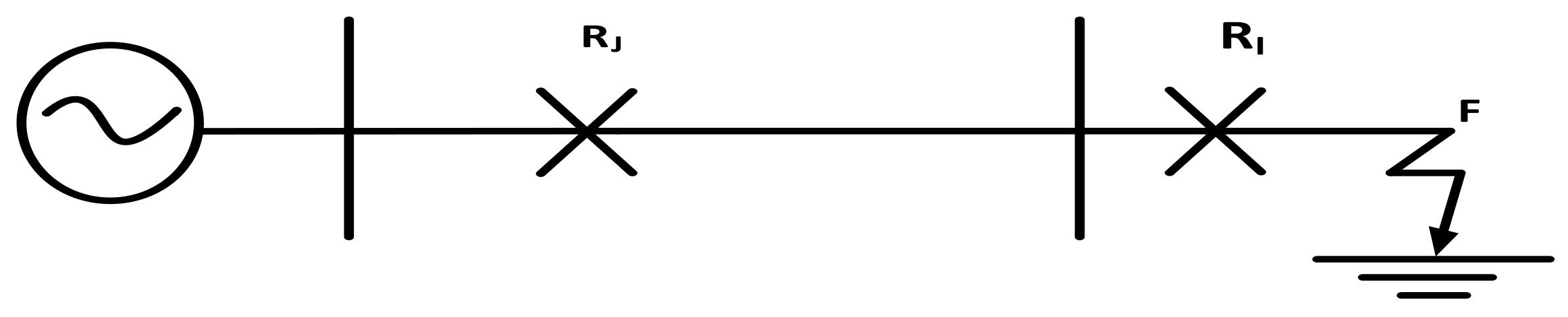
2. Formulation of the Overcurrent Relay Problem
Constraints
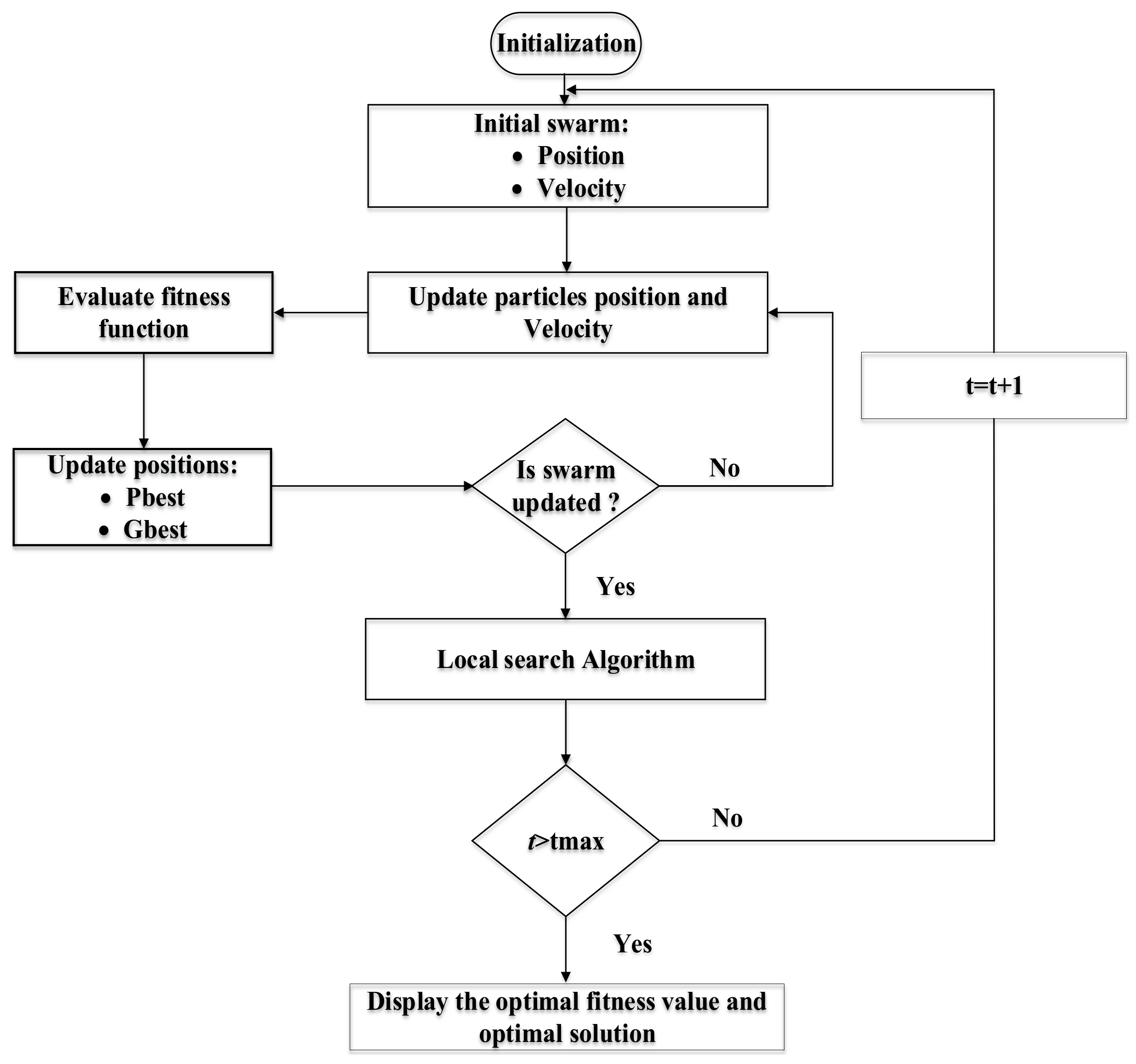
3. Continuous Particle Swarm Optimization
| Algorithm 1 scale equations to the same size as the rest of the text |
| 1. Set parameter wmin, wmax, c1, c2 and r1, r2 of PSO 2. Initialize population of particles as having positions X and velocities V 3. Set iteration k = 1 4. Calculate fitness of particles ∀i and find the index of the best particle b 5. Select and 6. w = wmax − k × (wmax − wmin)/Maxite 7. Update velocity and position of particles 8. Update Pbest population 9. If then Or else 10. If then and set b = b1 Or else 11. If K < Maxite then K = K + 1 and go to step 6 12. End while 13. End PSO-LS Or go to step 14 14. Display optimum solution as Gbestk |
4. Results and Discussion
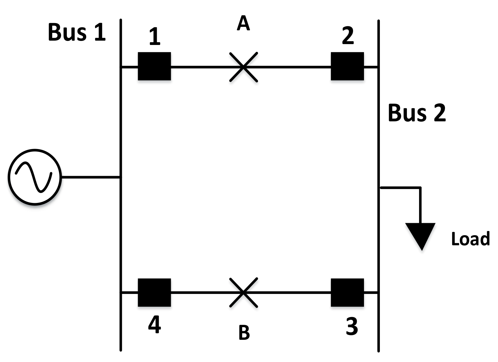
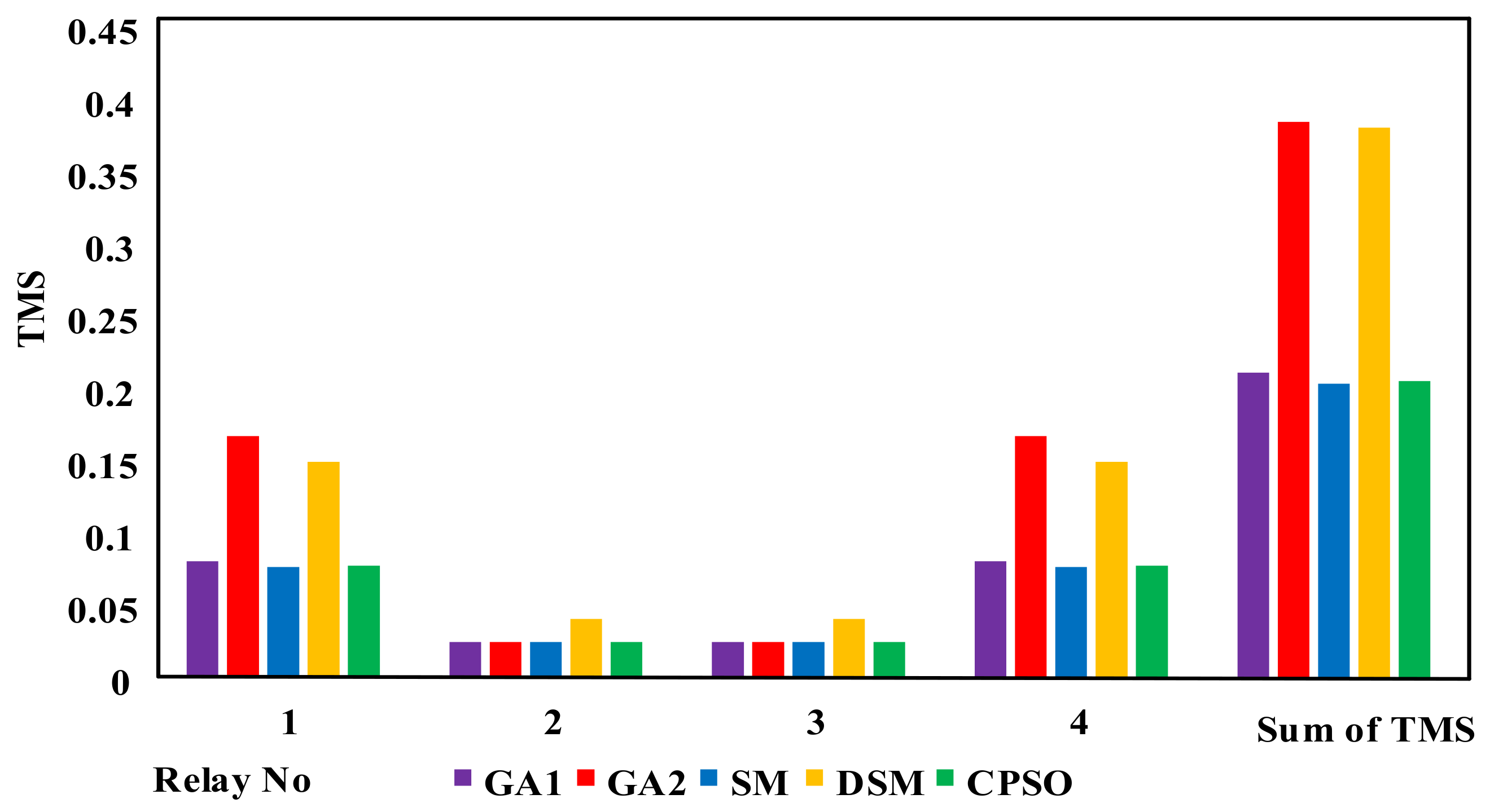
4.1. Case I
4.2. Case II
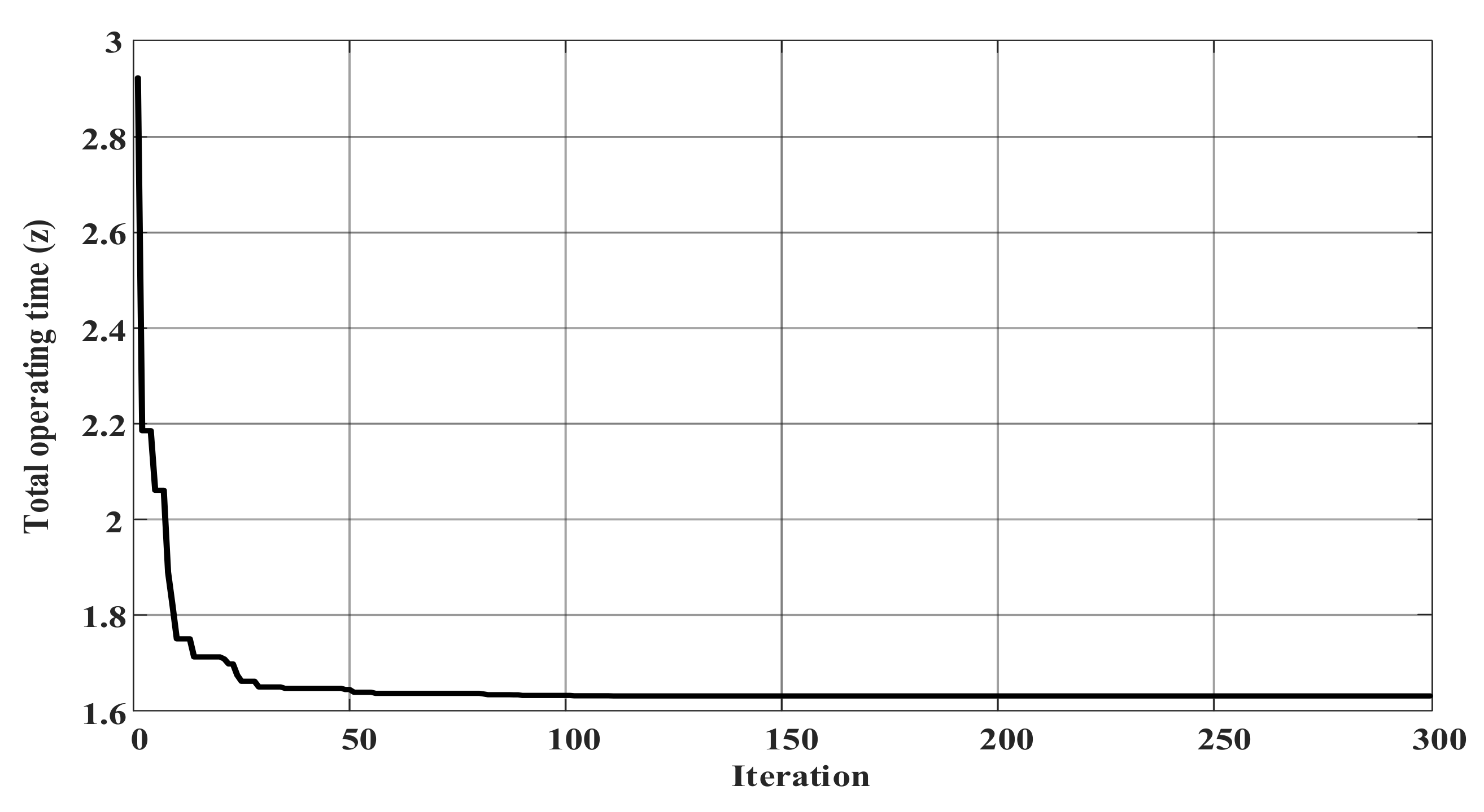
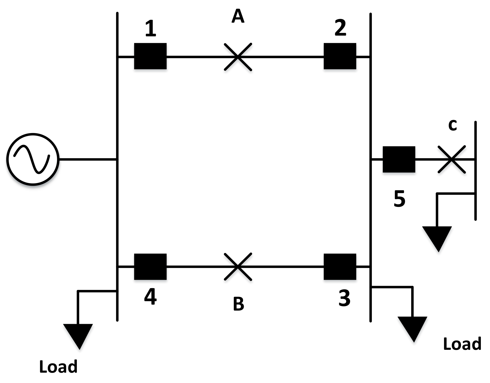
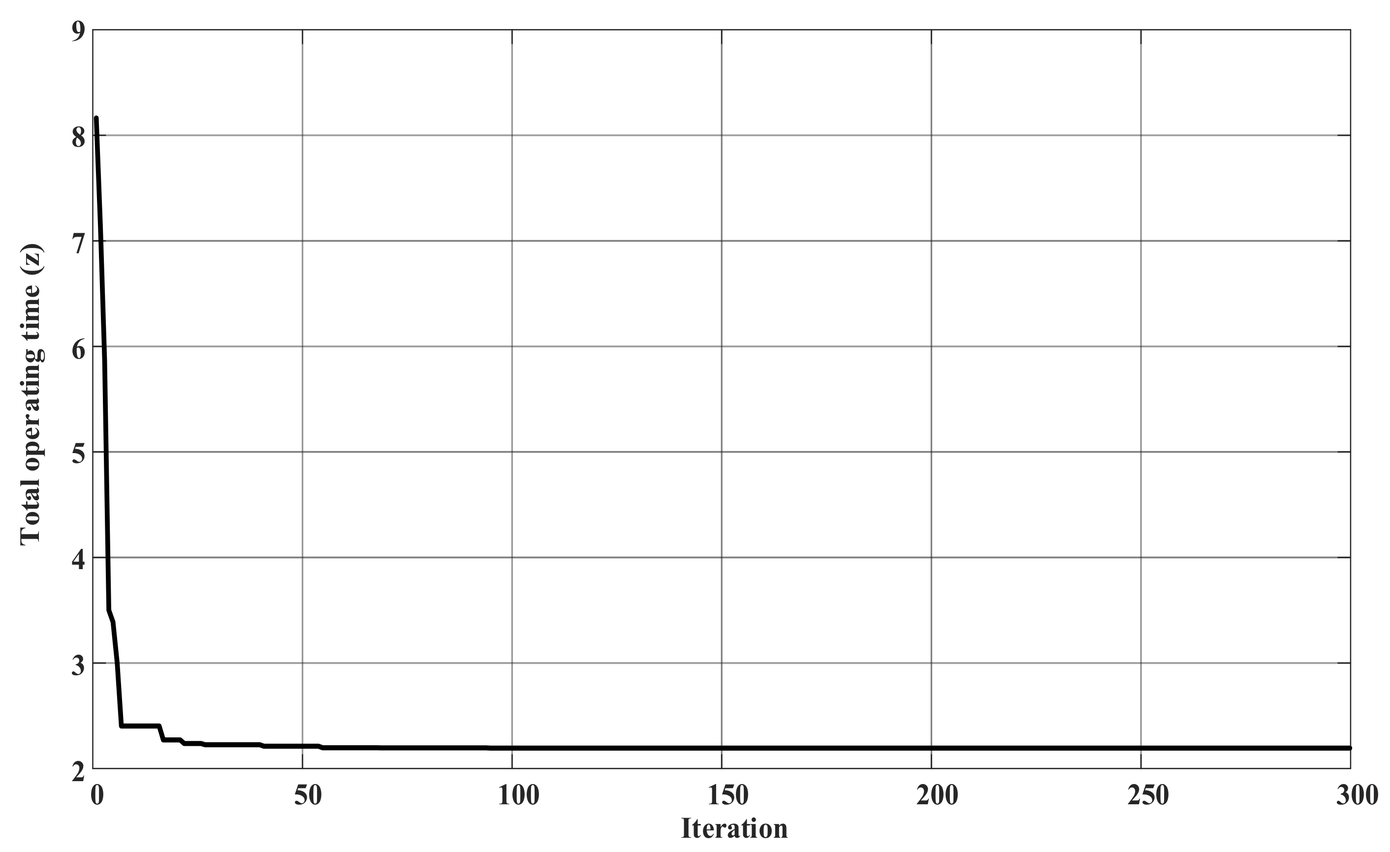
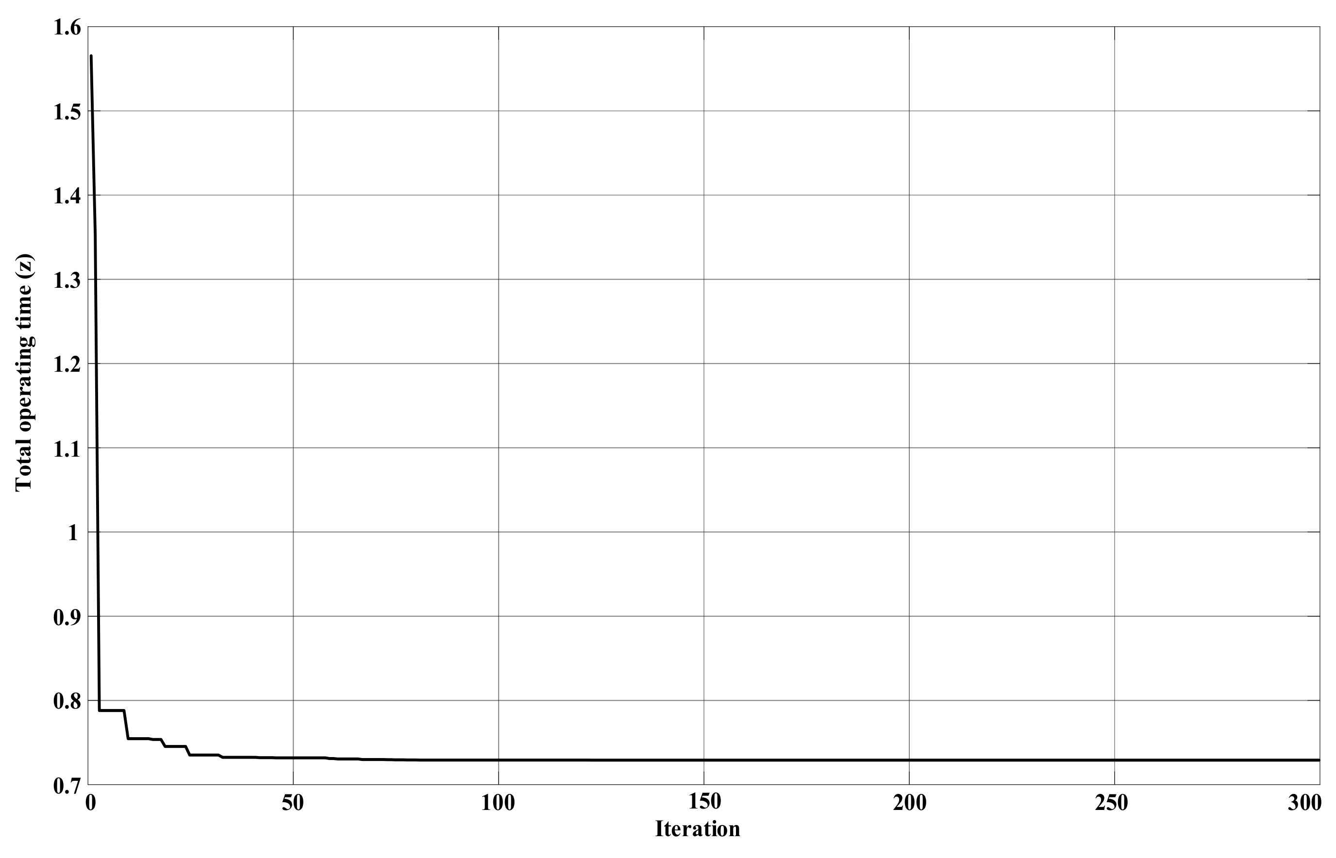
4.3. Case III
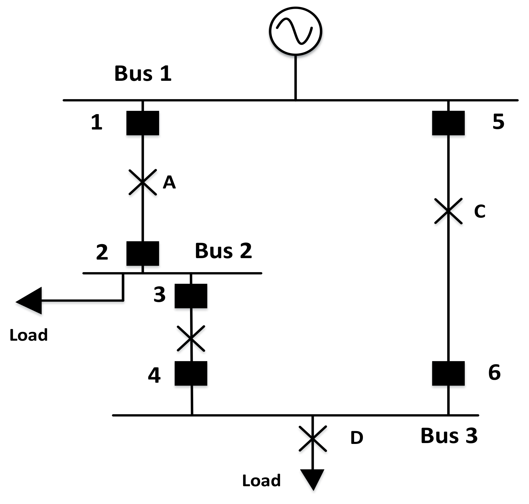
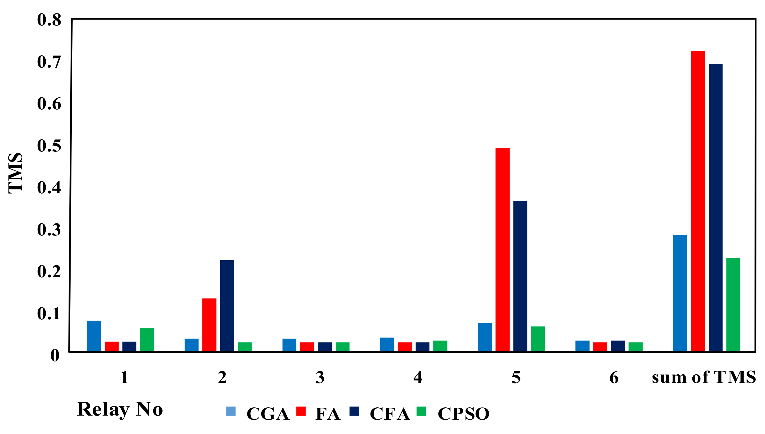
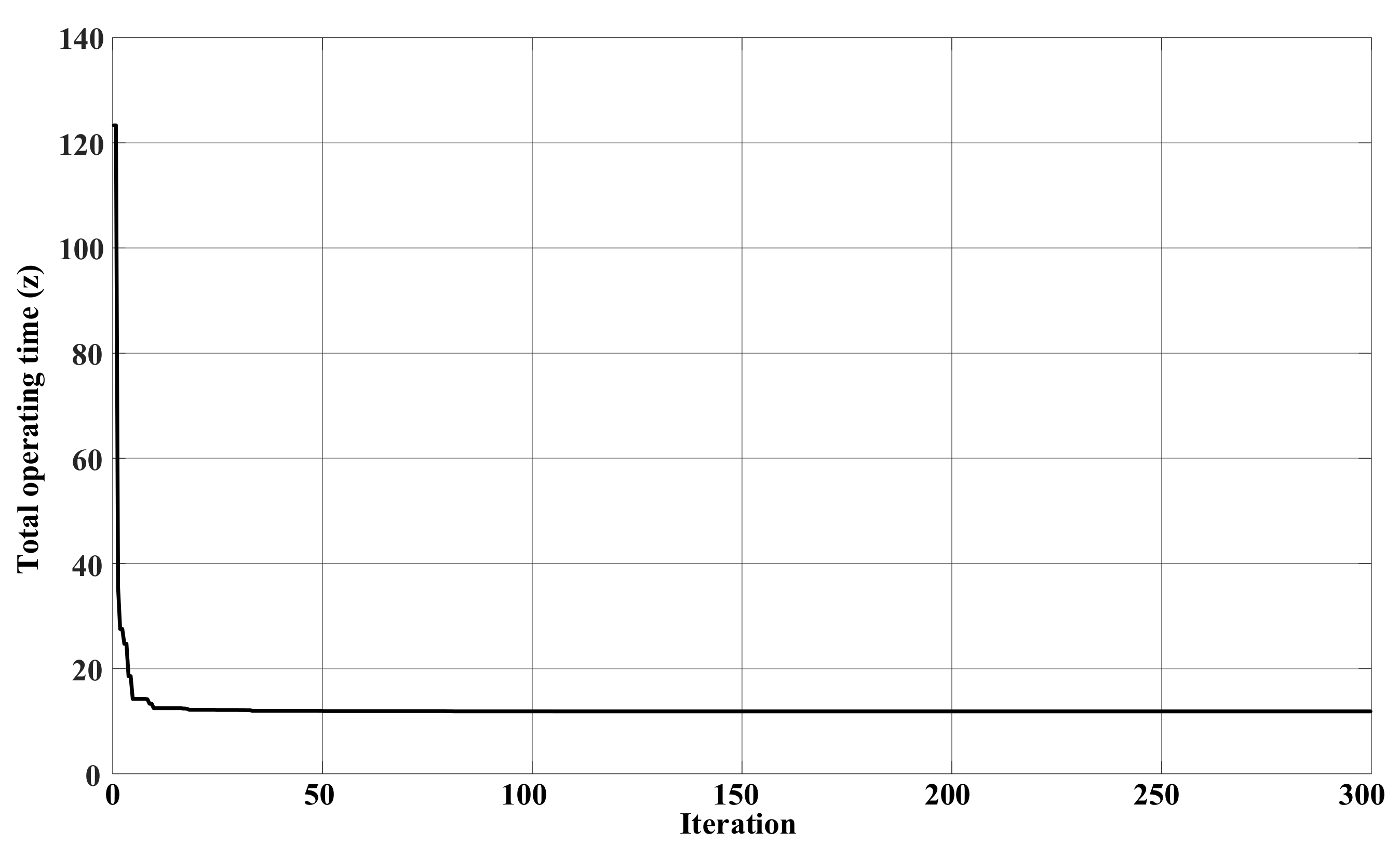
4.4. Case IV
5. Discussion
6. Conclusions
Acknowledgments
Author Contributions
Conflicts of Interest
References
- Blackburn, J. Protective Relaying, Principles and Applications; Marcel Dekker Inc.: New York, NY, USA, 1987. [Google Scholar]
- Urdaneta, A.J.; Nadira, R.; Jimenez, L.G.P. Optimal coordination of directional overcurrent relays in interconnected power systems. IEEE Trans. Power Deliv. 1988, 3, 903–911. [Google Scholar] [CrossRef]
- Perez, L.G.; Urdaneta, A.J. Optimal coordination of directional overcurrent relays considering definite time backup relaying. IEEE Trans. Power Deliv. 1999, 14, 1276–1284. [Google Scholar] [CrossRef]
- Birla, D.; Maheshwari, R.P.; Gupta, H.O. Time-overcurrent relay coordination: A review. Int. J. Emerg. Electr. Power Syst. 2005, 2. [Google Scholar] [CrossRef]
- Chattopadhyay, B.; Sachdev, M.S.; Sidhu, T.S. An on-line relay coordination algorithm for adaptive protection using linear programming technique. IEEE Trans. Power Deliv. 1996, 11, 165–173. [Google Scholar] [CrossRef]
- Birla, D.; Maheshwari, R.P.; Gupta, H.O.; Deep, K.; Thakur, M. Application of random search technique in directional overcurrent relay coordination. Int. J. Emerg. Electr. Power Syst. 2006, 7. [Google Scholar] [CrossRef]
- So, C.W.; Li, K.K. Time coordination method for power system protection by evolutionary algorithm. IEEE Trans. Ind. Appl. 2000, 36, 1235–1240. [Google Scholar] [CrossRef]
- Koochaki, A.; Asadi, M.R.; Mahmoodan, M.; Naghizadeh, R.A. Optimal overcurrent relays coordination using genetic algorithm. In Proceedings of the 11th International Conference on Optimization of Electrical and Electronic Equipment, Brasov, Romania, 22–24 May 2008. [Google Scholar]
- Bedekar, P.P.; Bhide, S.R. Optimum coordination of overcurrent relay timing using continuous genetic algorithm. Expert Syst. Appl. 2011, 38, 11286–11292. [Google Scholar] [CrossRef]
- So, C.W.; Li, K.K.; Lai, K.T.; Fung, K.Y. Application of genetic algorithm to overcurrent relay grading coordination. In Proceedings of the Sixth International Conference on Developments in Power System Protection, Nottingham, UK, 25–27 March 1997; pp. 283–287. [Google Scholar]
- Bedekar, P.P.; Bhide, S.R. Optimum coordination of directional overcurrent relays using the hybrid GA-NLP approach. IEEE Trans. Power Deliv. 2011, 26, 109–119. [Google Scholar] [CrossRef]
- Razavi, F.; Abyaneh, H.A.; Al-Dabbagh, M.; Mohammadi, R.; Torkaman, H. A new comprehensive genetic algorithm method for optimal overcurrent relays coordination. Electr. Power Syst. Res. 2008, 78, 713–720. [Google Scholar] [CrossRef]
- Noghabi, A.S.; Sadeh, J.; Mashhadi, H.R. Considering different network topologies in optimal overcurrent relay coordination using a hybrid GA. IEEE Trans. Power Deliv. 2009, 24, 1857–1863. [Google Scholar] [CrossRef]
- Rathinam, A.; Sattianadan, D.; Vijayakumar, K. Optimal coordination of directional overcurrent relays using particle swarm optimization technique. Int. J. Comput. Appl. 2010, 10, 43–47. [Google Scholar] [CrossRef]
- Zeineldin, H.H.; El-Saadany, E.F.; Salama, M.M.A. Optimal coordination of overcurrent relays using a modified particle swarm optimization. Electr. Power Syst. Res. 2006, 76, 988–995. [Google Scholar] [CrossRef]
- Mansour, M.M.; Mekhamer, S.F.; El-Kharbawe, N. A modified particle swarm optimizer for the coordination of directional overcurrent relays. IEEE Trans. Power Deliv. 2007, 22, 1400–1410. [Google Scholar] [CrossRef]
- Motlagh, M.; Hadi, S.; Mazlumi, K. Optimal Overcurrent Relay Coordination Using Optimized Objective Function. ISRN Power Eng. 2014, 2014. [Google Scholar] [CrossRef]
- Liu, A.; Yang, M.-T. A new hybrid nelder-mead particle swarm optimization for coordination optimization of directional overcurrent relays. Math. Probl. Eng. 2012, 2012. [Google Scholar] [CrossRef]
- Yang, M.-T.; Liu, A. Applying hybrid PSO to optimize directional overcurrent relay coordination in variable network topologies. J. Appl. Math. 2013, 2013. [Google Scholar] [CrossRef]
- Thangaraj, R.; Pant, M.; Deep, K. Optimal coordination of over-current relays using modified differential evolution algorithms. Eng. Appl. Artif. Intell. 2010, 23, 820–829. [Google Scholar] [CrossRef]
- Uthitsunthorn, D.; Pao-La-Or, P.; Kulworawanichpong, T. Optimal overcurrent relay coordination using artificial bees colony algorithm. In Proceedings of the 2011 8th International Conference on Electrical Engineering/Electronics, Computer, Telecommunications and Information Technology (ECTI-CON), Khon Kaen, Thailand, 17–19 May 2011. [Google Scholar]
- Xu, C.; Zou, X.; Yuan, R.; Wu, C. Optimal coordination of protection relays using new hybrid evolutionary algorithm. In Proceedings of the 2008 IEEE Congress on Evolutionary Computation (IEEE World Congress on Computational Intelligence), Hong Kong, China, 1–6 June 2008. [Google Scholar]
- Amraee, T. Coordination of directional overcurrent relays using seeker algorithm. IEEE Trans. Power Deliv. 2012, 27, 1415–1422. [Google Scholar] [CrossRef]
- Gokhale, S.S.; Kale, V.S. An application of a tent map initiated Chaotic Firefly algorithm for optimal overcurrent relay coordination. Int. J. Electr. Power Energy Syst. 2016, 78, 336–342. [Google Scholar] [CrossRef]
- Alam, M.N.; Das, B.; Pant, V. A comparative study of metaheuristic optimization approaches for directional overcurrent relays coordination. Electr. Power Syst. Res. 2015, 128, 39–52. [Google Scholar] [CrossRef]
- Alipour, M.; Teimourzadeh, S.; Seyedi, H. Improved group search optimization algorithm for coordination of directional overcurrent relays. Swarm Evol. Comput. 2015, 23, 40–49. [Google Scholar] [CrossRef]
- Sulaiman, M.; Ahmad, A.; Khan, A.; Muhammad, S. Hybridized Symbiotic Organism Search Algorithm for the Optimal Operation of Directional Overcurrent Relays. Complexity 2018, 2018. [Google Scholar] [CrossRef]
- Sulaiman, M.; Muhammad, H.; Khan, A. Improved Solutions for the Optimal Coordination of DOCRs Using Firefly Algorithm. Complexity 2018, 2018. [Google Scholar] [CrossRef]
- Ehrenberger, J.; Švec, J. Directional Overcurrent Relays Coordination Problems in Distributed Generation Systems. Energies 2017, 10, 1452. [Google Scholar] [CrossRef]
- Ates, Y.; Boynuegri, A.; Uzunoglu, M.; Nadar, A.; Yumurtacı, R.; Erdinc, O.; Paterakis, N.; Catalão, J. Adaptive protection scheme for a distribution system considering grid-connected and islanded modes of operation. Energies 2016, 9, 378. [Google Scholar] [CrossRef]
- Núñez-Mata, O.; Palma-Behnke, R.; Valencia, F.; Jiménez-Estévez, P.M.G. Adaptive Protection System for Microgrids Based on a Robust Optimization Strategy. Energies 2018, 11, 308. [Google Scholar] [CrossRef]
- Wadood, A.; Kim, C.-H.; Farkoush, S.G.; Rhee, S.B. An Adaptive Protective Coordination Scheme for Distribution System Using Digital Overcurrent Relays. In Proceedings of the Korean Institute of Illuminating and Electrical Installation Engineers, Gangwon, Korea, 30 August 2017; p. 53. [Google Scholar]
- Kennedy, J.; Eberhart, R. Particle swarm optimization (PSO). In Proceedings of the IEEE International Conference on Neural Networks, Perth, Australia, 27 November–1 December 1995; pp. 1942–1948. [Google Scholar]
- Shi, Y.; Eberhart, R. A modified particle swarm optimizer. In Proceedings of the 1998 IEEE International Conference on Evolutionary Computation Proceedings, IEEE World Congress on Computational Intelligence, Anchorage, AK, USA, 4–9 May 1998. Cat. No.98TH8360. [Google Scholar]
- Eberhart, R.C.; Hu, X. Human tremor analysis using particle swarm optimization. In Proceedings of the 1999 Congress on Evolutionary Computation, Washington, DC, USA, 6–9 July 1999; Volume 3. [Google Scholar]
- Park, J.B.; Lee, K.S.; Shin, J.R.; Lee, K.Y. A Particle swarm optimization for economic dispatch with non-smooth cost functions. IEEE Trans. Power Syst. 2005, 20, 34–42. [Google Scholar] [CrossRef]
- Eberhart, R.; Kennedy, J. A new optimizer using particle swarm theory. In Proceedings of the Sixth International Symposium on Micro Machine and Human Science, Nagoya, Japan, 4–6 October 1995. [Google Scholar]
- Sevkli, M.; Guner, A.R. A continuous particle swarm optimization algorithm for uncapacitated facility location problem. In Ant Colony Optimization and Swarm Intelligence; Springer: Berlin/Heidelberg, Germany, 2006. [Google Scholar]
- Emara, H.M.; Fattah, H.A.A. Continuous swarm optimization technique with stability analysis. In Proceedings of the American Control Conference, Boston, MA, USA, 30 June–2 July 2004. [Google Scholar]
- Khoshahval, F.; Zolfaghari, A.; Minuchehr, H.; Sadighi, M.; Norouzi, A. PWR fuel management optimization using continuous particle swarm intelligence. Ann. Nucl. Energy 2010, 37, 1263–1271. [Google Scholar] [CrossRef]
- Eberhart, R.C.; Shi, Y. Comparing inertia weights and constriction factors in particle swarm optimization. In Proceedings of the 2000 Congress on Evolutionary Computation, La Jolla, CA, USA, 16–19 July 2000. [Google Scholar]
- Bedekar, P.P.; Bhide, S.R.; Kale, V.S. Optimum coordination of overcurrent relay timing using simplex method. Electr. Power Compon. Syst. 2010, 38, 1175–1193. [Google Scholar] [CrossRef]
- Bedekar, P.P.; Bhide, S.R.; Kale, V.S. Optimum coordination of overcurrent relays in distribution system using dual simplex method. In Proceedings of the 2009 2nd International Conference on Emerging Trends in Engineering and Technology (ICETET), Nagpur, India, 16–18 December 2009. [Google Scholar]
- Bedekar, P.P.; Bhide, S.R.; Kale, V.S. Optimum time coordination of overcurrent relays using two phase simplex method. World Acad. Sci. Eng. Technol. 2009, 28, 1110–1114. [Google Scholar]


| Fault Point | Primary Relay | Backup Relay |
|---|---|---|
| A | 2 | 4 |
| B | 3 | 1 |
| Fault Point | 1 | 2 | 3 | 4 | |
|---|---|---|---|---|---|
| A | Irelay | 10 | 3.33 | - | 3.33 |
| 2.97 | 5.749 | - | 5.749 | ||
| B | Irelay | 3.33 | - | 3.33 | 10 |
| 5.749 | - | 5.749 | 2.97 | ||
| TMS | GA 1 [42] | GA 2 [42] | SM [42] | DSM [43] | CPSO |
|---|---|---|---|---|---|
| TMS 1 | 0.081 | 0.168 | 0.07718 | 0.15 | 0.078 |
| TMS 2 | 0.025 | 0.0250 | 0.0250 | 0.041 | 0.0250 |
| TMS 3 | 0.025 | 0.0250 | 0.0250 | 0.041 | 0.0250 |
| TMS 4 | 0.081 | 0.168 | 0.07718 | 0.15 | 0.078 |
| Top z (s) | 1.70 | 3.23 | 1.64 | 3.09 | 1.65 |
| Net Gain | CPSO/GA | CPSO/GA | CPSO/DSM |
|---|---|---|---|
| ∑∆(t)s | 0.05 | 1.58 | 1.44 |
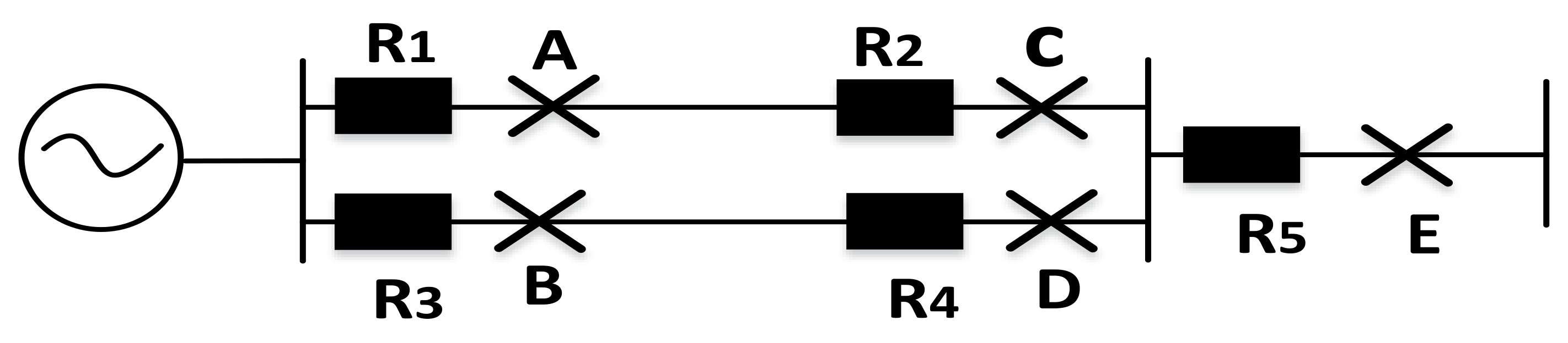
| Fault Point | Primary Relay | Backup Relay |
|---|---|---|
| A | 1 | - |
| B | 3 | - |
| C | 1, 2 | -, 3 |
| D | 3, 4 | -, 1 |
| E | 5 | 1, 3 |
| Relay | CT Ratio | Plug Setting |
|---|---|---|
| 1 | 300/1 | 1 |
| 2 | 300/1 | 1 |
| 3 | 300/1 | 1 |
| 4 | 300/1 | 1 |
| 5 | 100/1 | 1 |
| Fault Point | Relay | |||||
|---|---|---|---|---|---|---|
| 1 | 2 | 3 | 4 | 5 | ||
| A | Irelay | 42.34 | - | - | - | - |
| 1.799 | - | - | - | - | ||
| B | Irelay | - | 42.34 | - | - | - |
| - | 1.799 | - | - | - | ||
| C | Irelay | 4.876 | 4.876 | 4.876 | - | - |
| 4.348 | 4.348 | 4.348 | - | - | ||
| D | Irelay | 4.876 | - | 4.876 | 4.876 | - |
| 4.348 | - | 4.348 | 4.348 | - | ||
| E | Irelay | 4.876 | - | 4.876 | - | 29.25 |
| 4.348 | - | 4.348 | - | 2.004 | ||
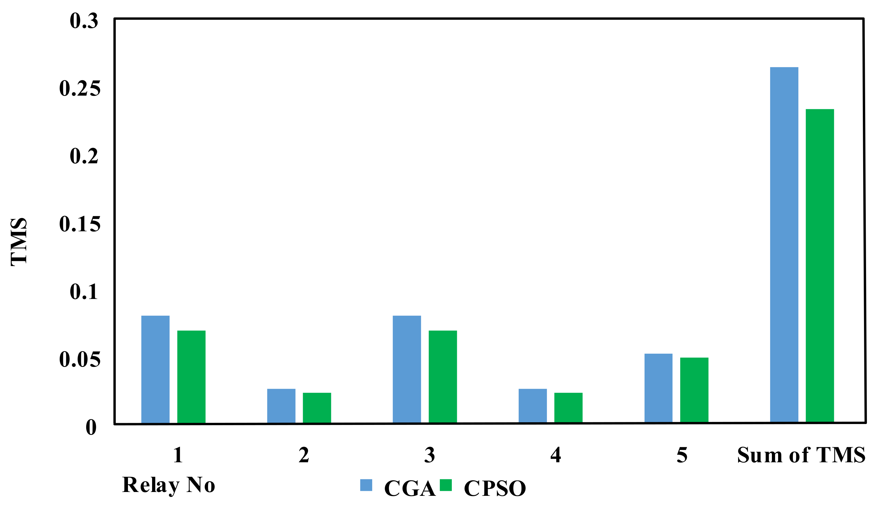
| TMS | CGA [9] | CPSO |
|---|---|---|
| TMS 1 | 0.08 | 0.0690 |
| TMS 2 | 0.026 | 0.0230 |
| TMS 3 | 0.08 | 0.0690 |
| TMS 4 | 0.026 | 0.0230 |
| TMS 5 | 0.052 | 0.0499 |
| Top (z) | 2.52 | 2.21 |
| Net Gain | ∑∆(t)s |
|---|---|
| CPSO/CGA | 0.31 |
| Fault Point | Relay | |||||
|---|---|---|---|---|---|---|
| 1 | 2 | 3 | 4 | 5 | ||
| A | Irelay | 9.059 | 3.019 | 3.019 | - | - |
| 3.106 | 6.265 | 6.265 | - | - | ||
| B | Irelay | 3.019 | - | 9.059 | 3.019 | - |
| 6.265 | - | 3.106 | 6.265 | - | ||
| C | Irelay | 4.875 | - | 4.875 | - | 29.25 |
| 4.348 | - | 4.348 | - | 2.004 | ||
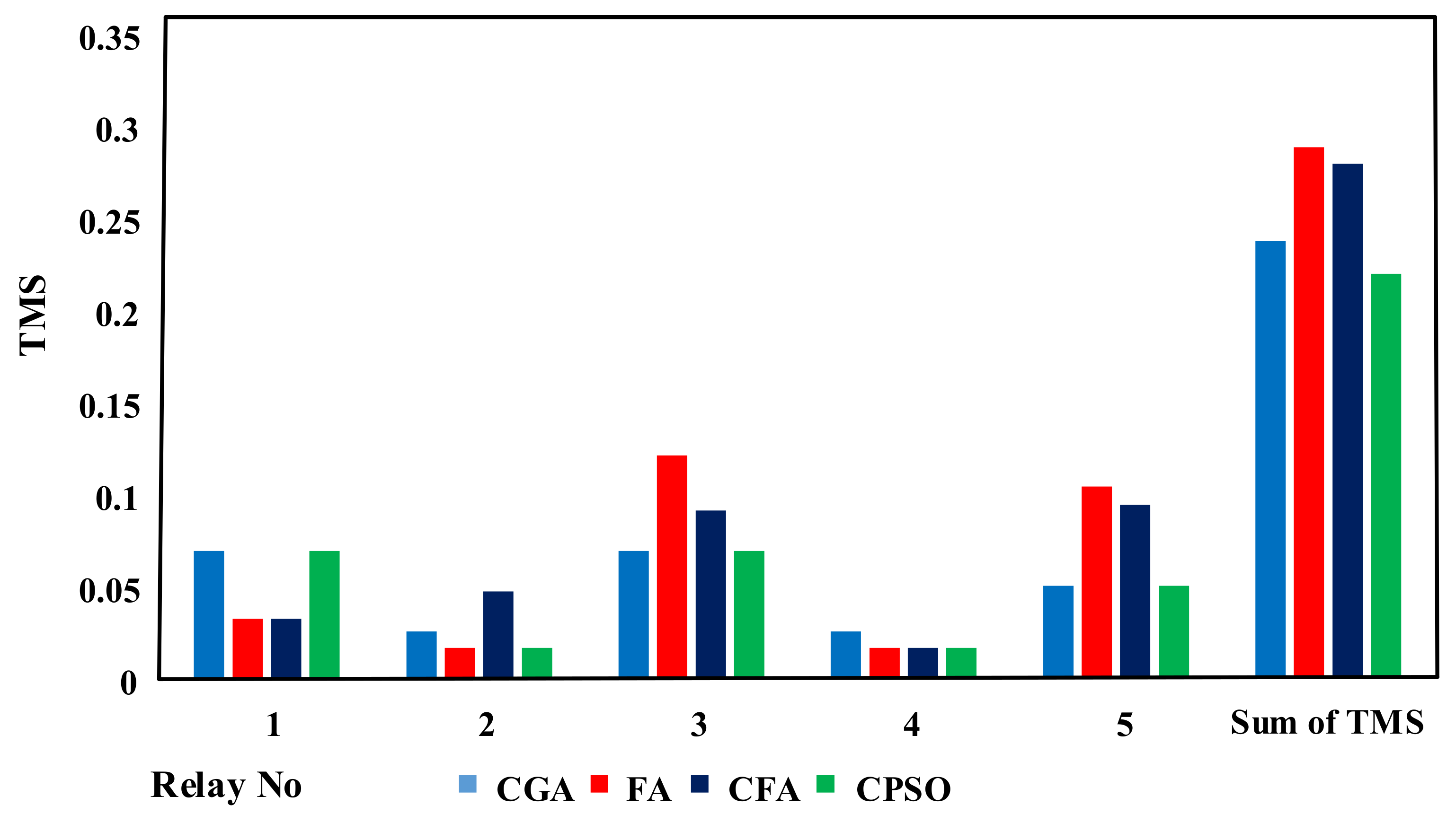
| TMS | TPSM [44] | CPSO 1 | FA [24] | CFA [24] | CPSO 2 |
|---|---|---|---|---|---|
| TMS 1 | 0.069 | 0.069 | 0.032 | 0.032 | 0.069 |
| TMS 2 | 0.025 | 0.0160 | 0.0160 | 0.047 | 0.0160 |
| TMS 3 | 0.069 | 0.069 | 0.121 | 0.091 | 0.069 |
| TMS 4 | 0.025 | 0.0160 | 0.0160 | 0.0160 | 0.0160 |
| TMS 5 | 0.0499 | 0.0499 | 0.104 | 0.094 | 0.0499 |
| Top z (s) | 2.27 | 2.17 | 1.73 | 1.63 | 0.7291 |
| Net Gain | ∑∆(t)s |
|---|---|
| CPSO 1/TPSM | 0.10 |
| CPSO 2/FA | 1.01 |
| CPSO 2/CFA | 0.91 |
| Line | Impedance (Ω) |
|---|---|
| 1-2 | 0.08j1 |
| 2-3 | 0.08 + j1 |
| 1-3 | 0.16 + j2 |
| Fault Point | Primary Relay | Backup Relay |
|---|---|---|
| A | 1, 2 | -, 4 |
| B | 3, 4 | 1, 5 |
| C | 5, 6 | -, 3 |
| D | 3, 5 | 1, - |
| Relay | CT Ratio | Plug Setting |
|---|---|---|
| 1 | 1000/1 | 1 |
| 2 | 300/1 | 1 |
| 3 | 1000/1 | 1 |
| 4 | 600/1 | 1 |
| 5 | 600/1 | 1 |
| 6 | 600/1 | 1 |
| Fault Point | Relay | ||||||
|---|---|---|---|---|---|---|---|
| 1 | 2 | 3 | 4 | 5 | 6 | ||
| A | Irelay | 6.579 | 3.13 | - | 1.565 | 1.565 | - |
| 3.646 | 6.065 | - | 15.55 | 15.55 | - | ||
| B | Irelay | 2.193 | - | 2.193 | 2.193 | 2.193 | - |
| 8.844 | - | 8.844 | 8.844 | 8.844 | - | ||
| C | Irelay | 1.096 | - | 1.096 | - | 5.482 | 1.827 |
| 75.91 | - | 75.91 | - | 4.044 | 11.539 | ||
| D | Irelay | 1.644 | - | 1.644 | - | 2.741 | - |
| 13.99 | - | 13.99 | - | 6.872 | - | ||
| TMS | CGA [9] | FA [24] | CFA [24] | CPSO |
|---|---|---|---|---|
| TMS 1 | 0.0765 | 0.027 | 0.027 | 0.0589 |
| TMS 2 | 0.034 | 0.130 | 0.221 | 0.0250 |
| TMS 3 | 0.0339 | 0.025 | 0.025 | 0.0250 |
| TMS 4 | 0.036 | 0.025 | 0.025 | 0.0290 |
| TMS 5 | 0.0711 | 0.489 | 0.363 | 0.0630 |
| TMS 6 | 0.0294 | 0.0285 | 0.029 | 0.0250 |
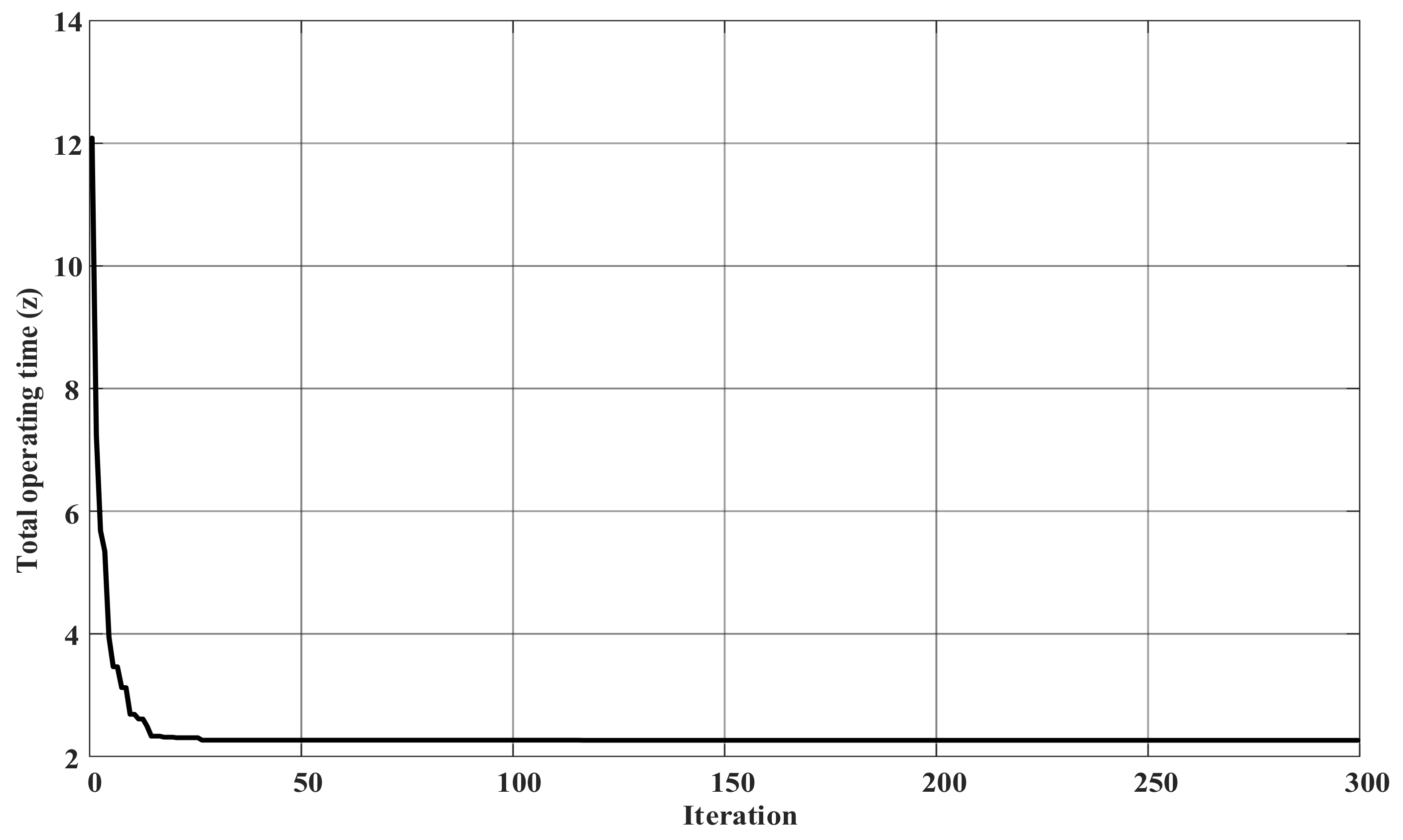
| Top z (s) | 15.88 | 16.25 | 14.39 | 11.87 |
| Method | Objective Function |
|---|---|
| CGA [9] | 15.88 |
| FA [21] | 16.25 |
| CFA [21] | 14.69 |
| Proposed CPSO | 11.87 |
| Net Gain | ∑∆(t)s |
|---|---|
| CPSO/CGA | 3.242 |
| CPSO/FA | 4.348 |
| CPSO/CFA | 2.82 |
© 2018 by the authors. Licensee MDPI, Basel, Switzerland. This article is an open access article distributed under the terms and conditions of the Creative Commons Attribution (CC BY) license (http://creativecommons.org/licenses/by/4.0/).
Share and Cite
Wadood, A.; Kim, C.-H.; Khurshiad, T.; Farkoush, S.G.; Rhee, S.-B. Application of a Continuous Particle Swarm Optimization (CPSO) for the Optimal Coordination of Overcurrent Relays Considering a Penalty Method. Energies 2018, 11, 869. https://doi.org/10.3390/en11040869
Wadood A, Kim C-H, Khurshiad T, Farkoush SG, Rhee S-B. Application of a Continuous Particle Swarm Optimization (CPSO) for the Optimal Coordination of Overcurrent Relays Considering a Penalty Method. Energies. 2018; 11(4):869. https://doi.org/10.3390/en11040869
Chicago/Turabian StyleWadood, Abdul, Chang-Hwan Kim, Tahir Khurshiad, Saeid Gholami Farkoush, and Sang-Bong Rhee. 2018. "Application of a Continuous Particle Swarm Optimization (CPSO) for the Optimal Coordination of Overcurrent Relays Considering a Penalty Method" Energies 11, no. 4: 869. https://doi.org/10.3390/en11040869