Article

Numerical Simulation of Flow and Heat Transfer in Structured Packed Beds with Smooth or Dimpled Spheres at Low Channel to Particle Diameter Ratio

Key Laboratory of Thermo-Fluid Science and Engineering, Ministry of Education, School of Energy and Power Engineering, Xi’an Jiaotong University, Xi’an 710049, China
*
Author to whom correspondence should be addressed.
Energies 2018, 11(4), 937; https://doi.org/10.3390/en11040937
Submission received: 1 March 2018 / Revised: 4 April 2018 / Accepted: 10 April 2018 / Published: 15 April 2018

Abstract

:
Packed beds are widely used in catalytic reactors or nuclear reactors. Reducing the pressure drop and improving the heat transfer performance of a packed bed is a common research aim. The dimpled structure has a complex influence on the flow and heat transfer characteristics. In the present study, the flow and heat transfer characteristics in structured packed beds with smooth or dimpled spheres are numerically investigated, where two different low channel to particle diameter ratios (N = 1.00 and N = 1.15) are considered. The pressure drop and the Nusselt number are obtained. The results show that, for N = 1.00, compared with the structured packed bed with smooth spheres, the structured packed bed with dimpled spheres has a lower pressure drop and little higher Nusselt number at 1500 < ReH < 14,000, exhibiting an improved overall heat transfer performance. However, for N = 1.15, the structured packed bed with dimpled spheres shows a much higher pressure drop, which dominantly affects the overall heat transfer performance, causing it to be weaker. Comparing the different channel to particle diameter ratios, we find that different configurations can result in: (i) completely different drag reduction effect; and (ii) relatively less influence on heat transfer enhancement.

1. Introduction

Packed beds are widely used in industrial applications, such as catalytic reactors or nuclear reactors. Reducing the pressure drop and improving the heat transfer performance a packed bed is a common research aim. Traditionally, a randomly packed bed is utilized due to the low cost and ease of use. The pressure drop of randomly packed beds, which is calculated by Ergun empirical correlation [1], is usually much higher than that of other packed beds, such as the structured packed bed. A novel type of structured catalytic reactor packing with a very low channel to particle diameter ratio (between 1.0 and 2.0) called composite structured packing (CSP) is reported by Strangio et al. [2]. This is a feasible way to achieve the structured packing form. Calis et al. [3] studied the flow characteristics of these CSP by computational fluid dynamics (CFD) and experiment. Five different channel to particle diameter ratio (N) packing forms were studied, as shown in Figure 1a. Their results showed that the pressure drop of these structured packed beds was lower than that of randomly packed beds. At the same time, they fitted a two-parameter pressure drop correlation for different N by using the CFD results. Rokmes et al. [4] numerically and experimentally investigated the heat transfer performance of these structured packed beds and gave correlations of Nusselt numbers by fitting the CFD results. Palle and Aliabadi [5] used direct numerical simulation for a structured packed bed in simple cubic (SC) configuration. They studied the friction factor for both infinite and wall bounded structured packed beds and proposed correlations for modified friction factor. Lin et al. [6] numerically studied two dimensional transient turbulent fluid flow and heat transfer in a packed sphere bed used in a regenerator furnace. In our group, Yang et al. [7] investigated flow and forced convective heat transfer in structured packed beds with spherical or ellipsoidal particles with symmetry boundary conditions. Wang et al. [8] designed a grille-sphere composite structured packed bed (GSCSPB), aiming to achieve the SC structured packing configuration easily, which is similar to N = 1.00 packing form, as shown in Figure 1b. Pressure drop and heat transfer performance of GSCSPB have been experimentally and numerically studied. The results showed that the GSCSPB can lower the pressure drop of the randomly packed bed and improve the heat transfer coefficient of the structured packed bed. Hu et al. [9] numerically studied the GSCSPB design parameters by using Taguchi method. All these works focus on packed beds with smooth particles at low channel to particle diameter ratios.
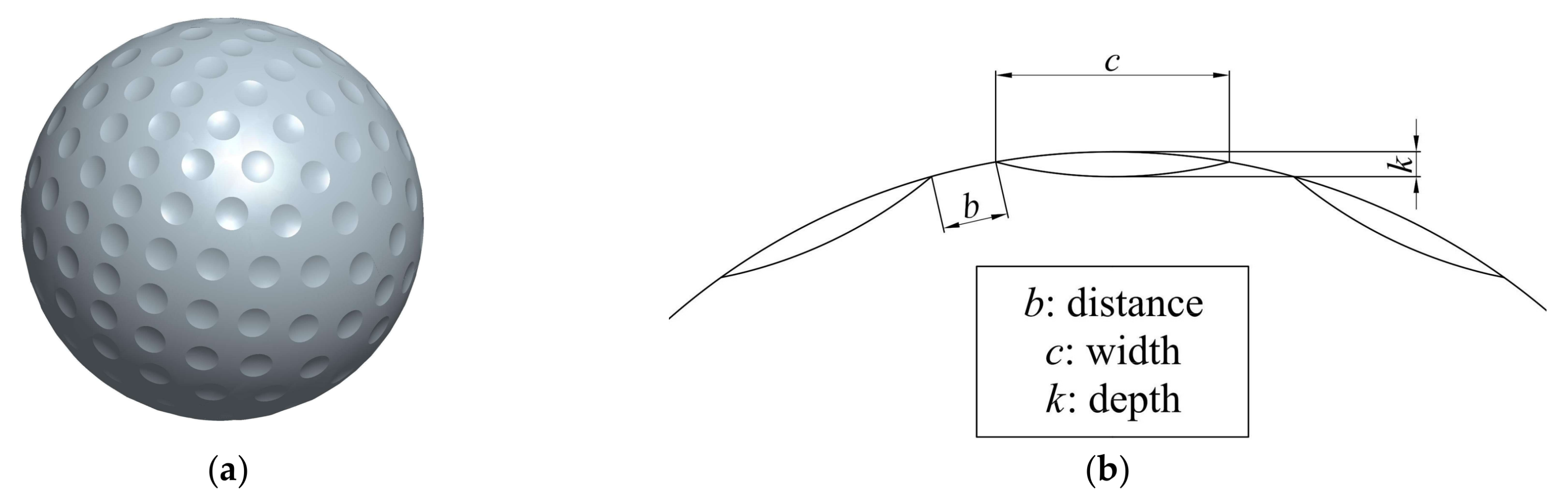
With different aerodynamic characteristics, a single dimpled sphere has been investigated by many researchers. Some studies show that the dimples on the sphere surface can reduce drag significantly at high Reynolds number. Jin et al. [10] measured the streamwise velocity above the dimpled surface to get a detailed mechanism of drag reduction by dimples on the surface. They considered that dimples caused local flow separation and large turbulence intensity. As a result, dimples delay the main separation and reduce drag significantly. Aoki et al. [11] applied the oil film method and particle image velocimetry (PIV) technology to obtain the flow pattern of the stationary and rotating dimple balls. Their results showed that, as the number of dimples became larger and the depth became deeper, the critical region shifted toward the lower Reynolds number range. Smith et al. [12] used direct numerical simulation to investigate the flow over a golf ball in the subcritical and supercritical regimes. Prediction of the drag coefficient was in reasonable agreement with measurements. At the same time, some researchers applied the dimpled structure to a rectangular channel [13,14] or shell and helically-coiled tube heat exchangers [15]. They all concluded that the dimpled structure could enhance heat transfer, while Kim et al. [15] found that the inline and staggered dimples showed the highest pressure drop.
Motivated by these researches, we wonder the influence of a series of dimpled spheres in wall bounded structured packed bed on flow and heat transfer performance, while the reference is rare. Since the dimpled surface can be approximately treated as roughness surface, we find an experimentally study about the influence of surface roughness on resistance to flow through randomly packed beds by Crawford and Plumb [16]. In their work, glass microspheres have been glued to smooth surfaces to obtain specific roughness. The results showed that the pressure drop was substantially increased by the presence of surface roughness. In 2017, Yang et al. [
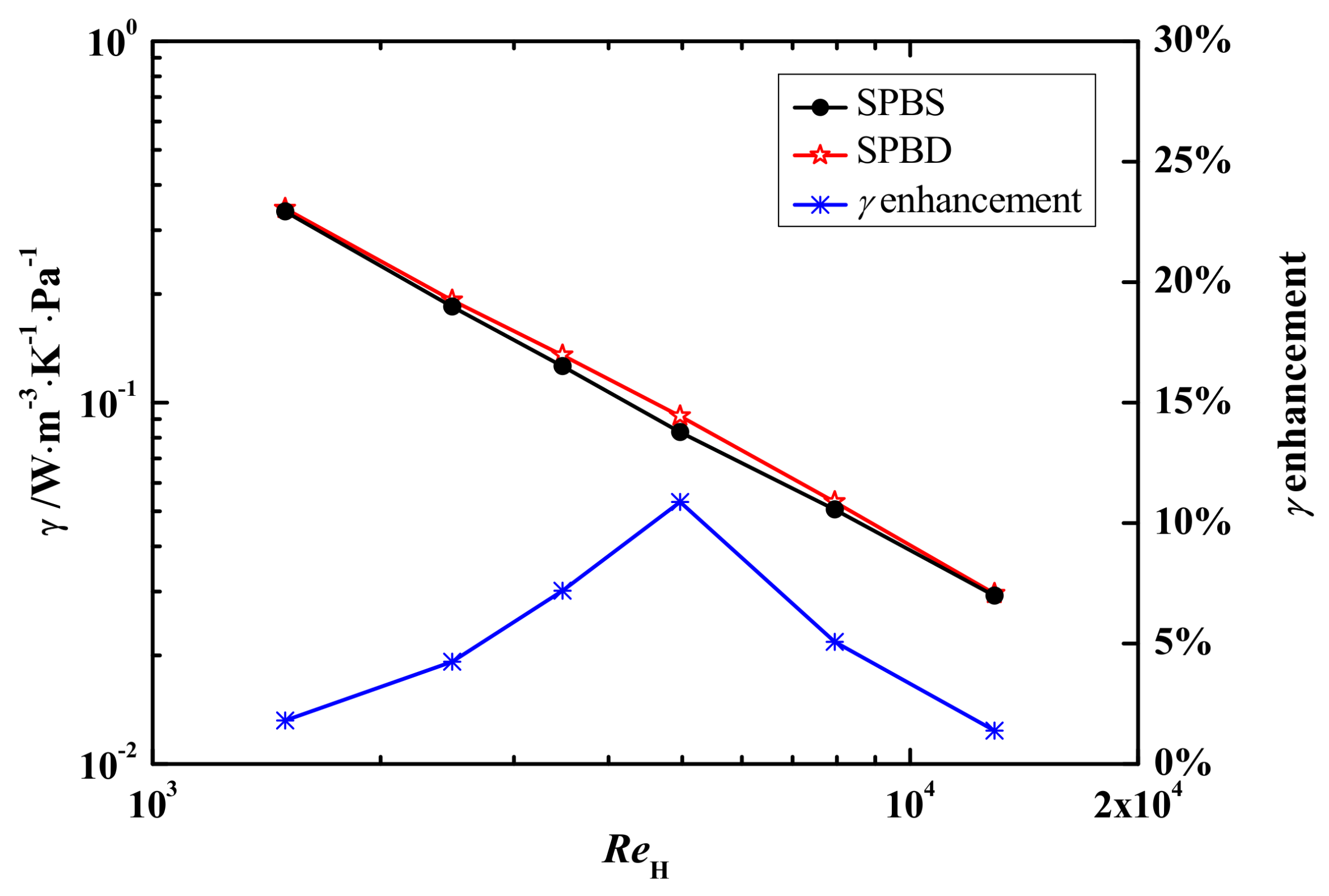
17] have initially studied the flow and heat transfer in infinite structured packed beds of dimple-particles with SC configuration by numerical simulation. The results showed that, the overall heat transfer efficiency can be improved by up to about 7% compared with the structured packed bed with smooth particles at the same inlet velocity condition.
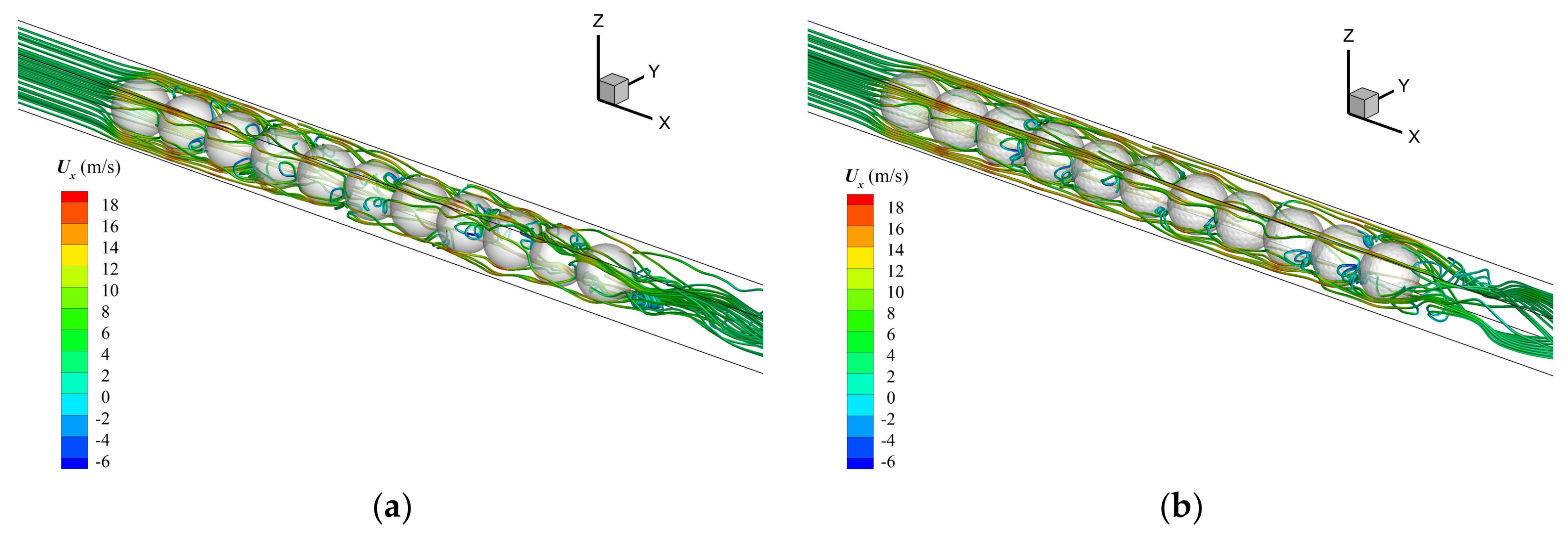
In the present study, the flow and heat transfer characteristics in wall bounded structured packed beds with smooth or dimpled spheres are numerically investigated. Two different low channel to particle diameter ratios (N = 1.00 and N = 1.15) are considered to investigate the influence of different configuration. The pressure drop and the Nusselt number are obtained by CFD and the overall heat transfer performance of packed bed with smooth or dimpled spheres is compared.

2. Computational Model and Method

2.1. Physical Model

The schematic of wall bounded structured packed beds are shown in Figure 2. The spheres are packed in the square cross-section channel. The channel to particle diameter ratio N is defined as the ratio of the sphere diameter (dp) to the width of square channel (H). The diameter of the spheres is 42.87 mm, while the widths of square channels are 42.87 mm and 49.30 mm respectively, obtained two packing configuration: N = 1.00 and N = 1.15. The packing with N = 1.00 is the simplest structured packed bed and the porosity ε equals 0.48. The packing with N = 1.15 is chosen to investigate the influence of small deviation of N and the porosity equals 0.60.
A uniform freestream velocity U0 at different Reynolds numbers with 0.5% turbulence intensity and constant temperature of air T0 = 293 K are applied to the domain inlet. The pressure outlet condition with zero gauge pressure is used at the domain outlet. The walls of the square channel are no-slip and adiabatic boundaries. The spheres surfaces are no-slip, constant temperature boundaries at Tp = 303 K, 10 K higher than the inlet temperature.
The dimpled sphere used in this study is shown in Figure 3. The size and shape of dimples refer to the experiment test balls by Aoki et al. [11], as shown in Table 1. We rebuilt this geometry of the dimpled sphere [17]. This dimpled sphere with 184 dimples on the surface is similar with the golf balls.

2.2. Computational Method

The hydraulic Reynolds number for packed bed in this study is based on the interstitial velocity (Ui) and hydraulic diameter (dH):
R e H = ρ U i d H μ ,
where the interstitial velocity (Ui) and hydraulic diameter (dH) are defined as follows:
U i = U 0 ε ,
d H = 4 V f A p + A w ,
where U0 is the superficial velocity and ε is the porosity of the packed part. Vf is the volume of fluid, Ap and Aw represent the surface area of particles and walls.
In order to analyse the hydrodynamics of the packed bed, we investigate the pressure drop through a unit length and friction factor f, defined as follows:
Δ p L = f 1 2 ρ U i 2 1 d H ,
At the same time, we study the heat transfer performance by obtaining the heat transfer coefficient and the average Nusselt number of one sphere in developed section of the packed bed:
h = q A p ( T p T f ) ,
N u = h d p λ ,
where dp is the diameter of particle, λ is the thermal conductivity. q is the particle-to-fluid heat transfer rate, Tp is the temperature of particle and Tf is the average of mass averaged temperature on the upstream and downstream cross-sections.
Considering the unit pressure drop and the heat transfer coefficient, we get overall heat transfer efficiency:
γ = h Δ p / L ,
In the numerical simulation, the geometric models are built by Pro/ENGINEER WILDFIRE 5.0 (5.0 Parametric Technology Corporation, Needham, MA, USA) and the unstructured grids are generated by ANSYS ICEM (14.5, ANSYS Inc., Cecil Township, PA, USA). To avoid the poor quality grids on the contact point, the diameters of the packed spheres are shrunk by 1%, same as the treatment in Ref. [3]. The hydraulic diameter, porosity and other parameters are calculated with 0.99 dp. For the same inlet velocity, the ReH has a little difference between the structured packed bed with smooth and dimpled spheres, due to a difference of 0.66% in surface area and a difference of 0.77% in volume of sphere. Since the difference is tiny, we assume the ReH of the structured packed bed with smooth and dimpled spheres to be the same for the convenience of the comparison. For the structured packed beds with smooth spheres (SPBS) and the structured packed beds with dimpled spheres (SPBD), four different grids are used for grid the independence test, respectively. The total elements numbers vary from 1,002,223 to 3,352,966 for SPBS, and from 1,276,351 to 3,774,227 for SPBD. As shown in Figure 4, the differences of the unit pressure drop between the largest two grids are about 0.83% and 0.28% for SPBS and SPBD. So, the most refined grids are chosen to get credible results. The mesh near the contact point of packed bed with dimple sphere is shown in Figure 5.
The three-dimensional Navier–Stokes and energy equations for steady state incompressible flow and heat transfer are used. The hydraulic Reynolds number ReH in this study is from 1500 to 14,000. The RNG k-ε model with scalable wall function is used as the turbulence model. The effect of swirl on turbulence is included in the RNG model, enhancing accuracy for swirling flows. Scalable wall functions avoid the deterioration of standard wall functions under grid refinement below y* < 11 [18]. The computations are performed using the commercial software ANSYS FLUENT (14.5, ANSYS Inc., Cecil Township, PA, USA). The SIMPLE algorithm is used for the pressure-velocity coupling in the Navier-Stokes equations. The Green-Gauss cell based scheme is used for the gradient and the second order upwind scheme is applied for the momentum, turbulence kinetic energy and dissipation rate, and energy equations.
The unit pressure drop and Nusselt number of the packed bed with smooth spheres at N = 1.00 are validated with the correlations by Calis et al. [3] and Rokmes et al. [4], as shown in Figure 6. The maximal and average deviations of friction factor are 9.1% and 5.4%, respectively. The maximal and average deviations of Nusselt number are 11.7% and 7.1%, respectively. Our results are in good agreement with the prediction results by these correlations.

3. Results and Discussion

3.1. N = 1.00 Packing

3.1.1. The Flow Characteristics

The dimpled structure has a complex influence on the flow characteristics. Firstly, the unit pressure drop and friction factor are discussed. The unit pressure drop is obtained by fitting the pressures and the location of the middle planes between adjacent spheres in packed bed, as shown in Table 2. In Table 2, it can be seen that the unit pressure drop of SPBD is smaller than that of SPBS at N = 1.00 in the range of simulated Reynolds number, with maximal and average differences about 7.4% and 4%, respectively. It means that the change from smooth spheres to dimpled spheres in packed bed could slightly reduce the drag of packed bed. The SPBD has a drag reduction effect at this configuration. The friction factor of SPBS and SPBD at N = 1.00, computed with the pressure drop and hydraulic diameter, is shown in Figure 7. We can see the apparent drag reduction in SPBD, especially when ReH > 4000.
In order to investigate why SPBD has a drag reduction effect at N = 1.00, we illustrate the streamlines of SPBS and SPBD as well as the streamwise velocity in the cross section near the 7th sphere, where the flow has been fully developed. In Figure 8, although there is a difference of about 7% between the friction factors of SPBS and SPBD at ReH = 5013, we could hardly find obvious distinctions between the streamlines. In a way, the streamlines are more continuous in the corner zone in SPBD. From Figure 9 we can see that the streamwise velocity in the corner zone on plane 1 and plane 3 of SPBD is a little larger than that of SPBS. The maximum streamwise velocity appears on plane 2 of SPBD is larger as well. We infer that the wake zone behind or near the dimpled spheres is larger than that of smooth spheres, resulting in more fluid flowing through the corner zone. This may cause the reductions of pressure drop and friction factor in SPBD.

3.1.2. The Heat Transfer Characteristics

The Nusselt number and heat transfer coefficient on the surface of one sphere in full development section in packed bed are computed. At N = 1.00, these characteristics are obtained on the 7th sphere of the 11 spheres packing, as shown in Table 3 and Figure 10. It can be seen that the heat transfer enhancement of SPBD is negative at low and high Reynolds number, namely that the heat transfer performance of SPBD is worse than that of SPBS in this situation. However, it increases with the ReH first and then decreases. The maximum of heat transfer enhancement of SPBD reaches to 6% at ReH about 3500.
Figure 11 shows the surface heat transfer coefficient of SPBS and SPBD at N = 1.00 (ReH = 3509). The zone A, which depicts the stronger heat transfer performance, is larger for the dimpled sphere than that for the smooth one. Similarly, the heat transfer weaker zone (zone B) in the back part of the dimpled spheres is smaller. However, it is found that surface heat transfer coefficient in each dimple is weaker than that in the surroundings. It means that the stagnation fluid in each dimple deteriorates the heat transfer from sphere to the main flow area. So, the enlargement of heat transfer enhanced area of SPBD is the dominant reason for the increase in the average heat transfer coefficient and Nusselt number.
Combining the effects of unit pressure drop and heat transfer coefficient, we calculated the overall heat transfer efficiency of SPBS and SPBD, as shown in Figure 12. The difference in overall heat transfer efficiency between SPBD and SPBS increases with the ReH first and then decreases, while it is always positive indicating that the overall heat transfer efficiency of SPBD can be improved in the range of simulated Reynolds number.
By analysing the flow and heat transfer characteristics of SPBS and SPBD at N = 1.00, it is concluded that, compared with SPBS, the SPBD shows a drag reduction about 4%, while the heat transfer enhancement increases with the ReH first and then decreases and the Nusselt number is slightly higher in a certain range. So, the overall heat transfer efficiency will be improved at the configuration of N = 1.00 packing.

3.2. N = 1.15 Packing

3.2.1. The Flow Characteristics

The pressure drop and friction factor of SPBS and SPBD at N = 1.15 are shown in Table 4 and Figure 13. Completely different from the N = 1.00 packing, the unit pressure drop of SPBD is much larger than that of SPBS. The negative sign of unit pressure drop reduction means that the SPBD has no drag reduction effect anymore. Averagely, the unit pressure drop increases by about 26.3%.
The streamlines of SPBS and SPBD at N = 1.15 are exhibited in Figure 14. Unlike the situation at N = 1.00, an obvious distinction in the streamlines between SPBS and SPBD at N = 1.15 is found. More streamlines are interrupted in the SPBD. We suppose that the stagger arrangement of the dimpled spheres and the existence of channel walls result in a more chaotic flow so that the backward flow behind every dimple spheres of SPBD is stronger. From Figure 15 we can see that, the streamwise velocity in the corner zones B and D of SPBD is larger than that of SPBS. However, the streamwise velocity in the corner zone A of SPBD is slower, especially on plane 2. So, we guess that, the more chaotic flow in SPBD brings greater viscous resistance. This may cause the increase in the pressure drop of the SPBD.

3.2.2. The Heat Transfer Characteristics

The Nusselt number and heat transfer coefficient of SPBS and SPBD are obtained on the 6th sphere of the 8 spheres packing at N = 1.15, where the flow has been fully developed, as shown in Table 5 and Figure 16. The heat transfer enhancement of SPBD is distinctly improved, by about 10%, compared with SPBS. Similarity to N = 1.00, it increases with the ReH first and then decreases.
Figure 17 shows the surface heat transfer coefficient of SPBS and SPBD at N = 1.15 (ReH = 4599). In the flow direction(x axis), the part of surface covered by the front sphere has a stronger heat transfer performance (zone A). The area of this part on the dimpled sphere surface is obviously larger than that on the smooth sphere. According to the conclusion in Section 3.1.2, the enlargement of heat transfer enhanced area of SPBD is the dominant reason for the increase in the average heat transfer coefficient. We also think that the enlargement of heat transfer enhanced area of SPBD might be the results of chaotic flow and wake zone enlargement.
The overall heat transfer efficiency of SPBS and SPBD at N = 1.15 is shown in Figure 18. Although the heat transfer coefficient of SPBD is improved by about 10%, the drag of SPBD largely increases resulting in a worse overall heat transfer efficiency compared with SPBS in the range of simulated Reynolds number.
From the analysis and discussion of the comparison of flow and heat transfer characteristics between SPBS and SPBD at N = 1.15, we have a brief summary. Compared with SPBS, the SPBD does not exhibit the drag reduction effect and the friction factor of SPBD increases by about 26.3%. Heat transfer enhancement distinctly improves by about 10%. However, the overall heat transfer performance of SPBD would be weaker at the configuration of N = 1.15 packing.

3.3. The Effect of Packing Configuration

Comparing the flow and heat transfer characteristics of different channel to particle diameter ratios, we find that, due to the combined effect of channel walls and dimpled surfaces, the flow in the wall bounded structured packed bed is quite complex. The drag reduction effect of SPBD turns into drag increasing effect as the channel to particle diameter ratio changes from N = 1.00 to N = 1.15. Therefore, we can also deduce that the drag coefficient of randomly packed beds with dimpled spheres may be larger than that with smooth spheres. At the same time, the heat transfer enhancement of SPBD strengthens with the channel to particle diameter ratio changing from N = 1.00 to N = 1.15. We think that the difference in the channel to particle diameter ratio has relatively less effect on the heat transfer enhancement.

4. Conclusions

The present study numerically investigated the flow and heat transfer characteristics in structured packed beds with smooth or dimpled spheres. Two different low channel to particle diameter ratios (N = 1.00 and N = 1.15) are simulated. The friction factor, Nusselt number and overall heat transfer efficiency are obtained. The conclusions are given as follows:
(1) For N = 1.00, the packed bed with dimpled spheres shows a little lower pressure drop and a slightly higher Nusselt number than those in the packed bed with smooth spheres, the overall heat transfer performance of packed bed with dimpled spheres would be improved. Therefore, the packed bed with dimpled spheres should be used in real applications to obtain a better overall performance at this configuration.
(2) For N = 1.15, the structured packed bed with dimpled spheres shows a much higher pressure drop, while the Nusselt number is still higher the overall heat transfer performance of a packed bed with dimpled spheres would be weaker. Therefore, the packed bed with dimpled spheres should be used when a better heat transfer performance is pursued in spite of the higher pressure drop in this configuration.
(3) Different channel to particle diameter ratios packing configuration can result in totally different drag reduction effect, while the heat transfer enhancement is relatively less affected.

Acknowledgments

We would like to acknowledge financial supports for this work provided by National Natural Science Foundation of China (No. 51536007, 51476124).

Author Contributions

Shiyang Li performed the numerical simulation and wrote the paper; Lang Zhou generated the geometry; Jian Yang contributed to writing and revising the paper; Qiuwang Wang supervised the work and revising the paper. All authors contributed to this work.

Conflicts of Interest

The authors declare no conflict of interest.

Nomenclature

Aarea (m2)
bdistance between dimples (m)
cwidth of dimple (m)
ddiameter (m)
ffriction factor
hheat transfer coefficient (W∙m2∙K)
Hwidths of the square channel (m)
kdepth of dimple (m)
Llength of the square channel
Nchannel to particle diameter ratio
NDthe number of dimples on the sphere
NuNusselt number
Δppressure drop (Pa)
qheat transfer rate (J∙s1)
ReHhydraulic Reynolds number
Ttemperature (K)
Uvelocity (m∙s1)
Vvolume (m3)
Greek letters
εporosity
ρdensity (kg∙m3)
μdynamic viscosity (kg∙m−1∙s−1)
λthermal conductivity (W∙m1∙K1)
γoverall heat transfer efficiency (W∙m3∙K1∙Pa1)
Subscripts
0initial state at inlet
ffluid
iinterstitial
Hhydraulic
pparticle
wwall

References

  1. Ergun, S. Fluid flow through packed columns. Chem. Eng. Prog. 1952, 48, 89–94. [Google Scholar]
  2. Strangio, V.A.; Dautzenberg, F.M.; Calis, H.P.A.; Gupta, A. Fixed Catalytic Bed Reactor. International Patent Application PCT/US99/06242, 23 March 1998. [Google Scholar]
  3. Calis, H.P.A.; Nijenhuis, J.; Paikert, B.C.; Bleek, C.M.V.D. CFD modelling and experimental validation of pressure drop and flow profile in a novel structured catalytic reactor packing. Chem. Eng. Sci. 2001, 56, 1713–1720. [Google Scholar] [CrossRef]
  4. Romkes, S.J.P.; Dautzenberg, F.M.; Bleek, C.M.V.D.; Calis, H.P.A. CFD modelling and experimental validation of particle-to-fluid mass and heat transfer in a packed bed at very low channel to particle diameter ratio. Chem. Eng. J. 2003, 96, 3–13. [Google Scholar] [CrossRef]
  5. Palle, S.; Aliabadi, S. Direct simulation of structured wall bounded packed beds using hybrid fe/fv methods. Comput. Fluids 2013, 88, 730–742. [Google Scholar] [CrossRef]
  6. Lin, C.N.; Jang, J.Y.; Lai, Y.S. Two Dimensional Thermal-Hydraulic Analysis for a Packed Bed Regenerator Used in a Reheating Furnace. Energies 2016, 9, 995. [Google Scholar] [CrossRef]
  7. Yang, J.; Wang, Q.; Zeng, M.; Nakayama, A. Computational study of forced convective heat transfer in structured packed beds with spherical or ellipsoidal particles. Chem. Eng. Sci. 2010, 65, 726–738. [Google Scholar] [CrossRef]
  8. Wang, J.; Yang, J.; Cheng, Z.; Liu, Y.; Chen, Y.; Wang, Q. Experimental and numerical study on pressure drop and heat transfer performance of grille-sphere composite structured packed bed. Appl. Energ. 2017, in press. [Google Scholar] [CrossRef]
  9. Hu, Y.; Yang, J.; Wang, J.; Zhou, L.; Li, S.; Wang, Q. Numerical study of forced convective heat transfer in grille-sphere composite packed bed with Taguchi-CFD method. Chem. Eng. Trans. 2017, 61, 313–318. [Google Scholar]
  10. Jin, C.; Jeon, W.P.; Choi, H. Mechanism of drag reduction by dimples on a sphere. Phys. Fluids 2006, 18, 112. [Google Scholar] [CrossRef]
  11. Aoki, K.; Ohike, A.; Yamaguchi, K.; Nakayama, Y. Flying characteristics and flow pattern of a sphere with dimples. J. Visual-Japan 2003, 6, 67–76. [Google Scholar] [CrossRef]
  12. Smith, C.E.; Beratlis, N.; Balaras, E.; Squires, K.; Tsunoda, M. Numerical investigation of the flow over a golf ball in the subcritical and supercritical regimes. Int. J. Heat Fluid Flow 2010, 31, 262–273. [Google Scholar] [CrossRef]
  13. Burgess, N.K.; Ligrani, P.M. Effects of Dimple Depth on Channel Nusselt Numbers and Friction Factors. J. Heat Trans.-T. ASME 2005, 127, 839–847. [Google Scholar] [CrossRef]
  14. Samad, A.; Lee, K.D.; Kim, K.Y. Shape Optimization of a Dimpled Channel to Enhance Heat Transfer Using a Weighted-Average Surrogate Model. Heat Transf. Eng. 2010, 31, 1114–1124. [Google Scholar] [CrossRef]
  15. Kim, S.M.; Jo, J.H.; Lee, Y.E.; Yoo, Y.S. Comparative Study of Shell and Helically-Coiled Tube Heat Exchangers with Various Dimple Arrangements in Condensers for Odor Control in a Pyrolysis System. Energies 2016, 9, 1027. [Google Scholar] [CrossRef]
  16. Crawford, C.W.; Plumb, O.A. The influence of surface roughness on resistance to flow through packed beds. J. Fluid Eng.-T. ASME 1986, 108, 343. [Google Scholar] [CrossRef]
  17. Yang, J.; Zhou, L.; Hu, Y.; Li, S.; Wang, Q. Numerical study of forced convective heat transfer in structured packed beds of dimple-particles. Heat Transf. Eng. 2017, in press. [Google Scholar] [CrossRef]
  18. ANSYS Inc. ANSYS User and Theory Guide, ANSYS Fluent, Release 14.5; ANSYS Inc.: Cecil Township, PA, USA, 2012. [Google Scholar]
Figure 1. Schematic of (a) composite structured packing (CSP) by Calis et al. [3] and Rokmes et al. [4]; and (b) grille-sphere composite structured packed bed (GSCSPB) by Wang et al. [8].
Energies 11 00937 g001
Figure 2. Schematic of wall bounded structured packed beds for (a) N = 1.00; and (b) N = 1.15.
Energies 11 00937 g002
Figure 3. (a) The dimpled sphere; and (b) the detail view of the dimples.
Energies 11 00937 g003
Figure 4. The unit pressure drop for (a) structured packed beds with smooth spheres (SPBS); and (b) structured packed beds with dimpled spheres (SPBD) with different grids.
Energies 11 00937 g004
Figure 5. The mesh near the contact point of packed bed with dimple sphere.
Energies 11 00937 g005
Figure 6. Validation of (a) friction factor; and (b) Nusselt number of the packed bed with smooth spheres at N = 1.00.
Energies 11 00937 g006
Figure 7. The friction factor of the structured packed bed with smooth or dimpled spheres at N = 1.00.
Energies 11 00937 g007
Figure 8. The streamlines of (a) SPBS; and (b) SPBD at N = 1.00 (ReH = 5013).
Energies 11 00937 g008
Figure 9. The streamwise velocity in the cross sections of (a) SPBS and (b) SPBD at N = 1.00 (ReH = 5013).
Energies 11 00937 g009
Figure 10. The Nusselt number of the structured packed bed with smooth or dimpled spheres at N = 1.00.
Energies 11 00937 g010
Figure 11. The surface heat transfer coefficient on a smooth or dimpled sphere in packed bed at N = 1.00 (ReH = 3509) for (a) smooth spheres packed bed and (b) dimpled spheres packed bed.
Energies 11 00937 g011
Figure 12. The overall heat transfer efficiency of the structured packed bed with smooth or dimpled spheres at N = 1.00.
Energies 11 00937 g012
Figure 13. The friction factor of the structured packed bed with smooth or dimpled spheres at N = 1.15.
Energies 11 00937 g013
Figure 14. The streamlines of the structured packed bed with smooth or dimpled spheres at N = 1.15 (ReH = 4599) for (a) smooth spheres packed bed and (b) dimpled spheres packed bed.
Energies 11 00937 g014
Figure 15. The streamwise velocity in the cross sections of (a) SPBS and (b) SPBD at N = 1.15 (ReH = 4599).
Energies 11 00937 g015
Figure 16. The Nusselt number of the structured packed bed with smooth or dimpled spheres at N = 1.15.
Energies 11 00937 g016
Figure 17. The surface heat transfer coefficient on a smooth or dimpled sphere in packed bed at N = 1.15 (ReH = 4599) for (a) smooth spheres packed bed and (b) dimpled spheres packed bed.
Energies 11 00937 g017
Figure 18. The overall heat transfer efficiency of the structured packed bed with smooth or dimpled spheres at N = 1.15.
Energies 11 00937 g018
Table 1. The geometry parameters of dimples.
NDb (mm)c (mm)k (mm)
1842.0433.5280.338
Table 2. The unit pressure drop of the structured packed beds with smooth or dimpled spheres at N = 1.00 (Pa∙m1).
ReHSPBSSPBDUnit Pressure Drop Reduction
1504114.0106.46.63%
2506297.6296.80.27%
3509544.7540.90.68%
50131066.8987.67.42%
80212554.02409.55.66%
13,0336388.86204.72.88%
Table 3. The Nusselt number of the structured packed beds with smooth or dimpled spheres at N = 1.00.
ReHSPBSSPBDHeat Transfer Enhancement
150468.264.9−4.94%
250697.1100.93.96%
3509121.6129.56.46%
5013156.4160.52.65%
8021228.8226.8−0.87%
13,033330.3325.2−1.54%
Table 4. The unit pressure drop of the structured packed beds with smooth or dimpled spheres at N = 1.15 (Pa∙m1).
ReHSPBSSPBDUnit Pressure Drop Reduction
184031.439.5−25.45%
321991.0117.9−29.62%
4599183.4232.9−26.98%
13,7971528.01883.0−23.23%
Table 5. The Nusselt number of the structured packed beds with smooth or dimpled spheres at N = 1.15.
ReHSmooth Spheres Packed BedDimpled Spheres Packed BedHeat Transfer Enhancement
184047.652.410.09%
321972.181.112.51%
459993.1105.613.36%
13,797208.0217.54.56%

