Abstract
In this research paper, a hybrid Artificial Neural Network (ANN)-Fuzzy Logic Control (FLC) tuned Flower Pollination Algorithm (FPA) as a Maximum Power Point Tracker (MPPT) is employed to amend root mean square error (RMSE) of photovoltaic (PV) modeling. Moreover, Gaussian membership functions have been considered for fuzzy controller design. This paper interprets the Luo converter occupied brushless DC motor (BLDC)-directed PV water pump application. Experimental responses certify the effectiveness of the suggested motor-pump system supporting diverse operating states. The Luo converter, a newly developed DC-DC converter, has high power density, better voltage gain transfer and superior output waveform and can track optimal power from PV modules. For BLDC speed control there is no extra circuitry, and phase current sensors are enforced for this scheme. The most recent attempt using adaptive neuro-fuzzy inference system (ANFIS)-FPA-operated BLDC directed PV pump with advanced Luo converter, has not been formerly conferred.
1. Introduction
As conventional energy sources are depleting day by day, the demand forrenewable energy sources is raising [1,2,3]. Solar energy sources are promising renewable energy sources for developed and developing nations due to being free, abundant, and environmentally friendly. Standalone photovoltaic (PV) systems for water-pumping applications are employed in remote areas [4,5]. Because of grid absence in remote places, standalone PV water pumping is installed for agricultural and household applications. Various electric motors have been used to drive the pumping system [6,7]. The DC motor-based pumping system requires maintenance because of commutator and brush presence. Therefore, DC motors are not frequently used for PV pumping applications. Single-phase induction motors have also been used for driving low-inertia torque load. Due to a complex control strategy, the induction motors are not efficient for pumping applications. Therefore, in this research work, a brushless DC (BLDC) motor has been considered as it has simple design control, low power range and requires maintenance-free operation compared to AC motors [8]. Distinct DC-DC converters were contenders for optimizing PV module generated power with a soft-starting and controlling motor pump system [9,10,11]. The contemporary PV system has insubstantial converse competency. Therefore, Maximum Power Point Trackers (MPPT) is the indispensable constituents required for optimal power tracking from PV modules. Numerous MPPT methods have been occupied viz. Perturb and Observe (P&O), Increment Conductance (INC), Fraction Short/Open circuit etc. [12,13,14]. Under steady-state operating conditions, particular algorithms provide high outturn. However, these algorithms are found lacking under adverse weather conditions showing slow convergence velocity and being unable to achieve a global power point (GPP) for partial shading situations with high power oscillations around this point. Recently, different intelligent techniques viz. Fuzzy Logic Control (FLC) and Artificial Neural Network (ANN) have been employed for PV tracking [15]. However, because of complex fuzzy inference rules and individual sensor requirements, meta-heuristic algorithms have been employed recently. Genetic algorithms and artificial immune systems (AIS) are meta-heuristic algorithms used for non-linear stochastic problem solutions [16,17]. These algorithms are capable to resolve non-linear complication. However, due to a large population size and adaptive immune cell mechanism, the GA and AIS algorithms, respectively, have low velocity of convergence with large computational period. However, the implementation of selection, mutation and crossover process is complex with reduced convergence computational period. Currently, bio-inspired and swarm optimization have been derived as MPPT techniques. The particle swarm optimization is an evolutionary methodology based onthe nature of a swarm that can reduce oscillations around GPP [18]. The classical particle swarm optimization PSO technique has randomness in acceleration value with high regulation parameters as major problems. Nevertheless, variance of this algorithm is capitulated when randomness is miniaturized. Surrogating to swarm techniques, current bio-inspired algorithms viz. Firefly Algorithms (FA), Artificial Bee Colony (ABC), Cuckoo Search etc. are considered as bio-inspired MPPT and have the advantages of high convergence speed, and less transience with fast tracked performance [19,20,21]. Nevertheless, because of a lower number of bees, ABC technique has a slow velocity of convergence under fluctuating weather situations. Because of the deviating movement of a large number of fireflies, the response of the system becomes slow with the prerequisite high computational period. The Cuckoo search algorithm provides an efficient solution to non-linear problems. However, because of complex nest population and inadequate contingency, the Cuckoo technique has slow convergence velocity under varying environmental conditions. However, the implementation complexities with the tuning of parameters are amajor hindrance of this finding. The above-mentioned algorithms’ drawbacks can be handled by applying Flower Pollination (FPA) as an MPPT technique. Ram et al. [22] has discussed the FPA algorithm for PV MPPT under dynamic operating conditions. This algorithm provides single-stage global searching, simpler coding, and lower tuned specification requirements with low cost implementation and has fast response compared to P&O and PSO techniques under dynamic weather conditions. Included in this work, a novel flower pollination algorithm is contemplated and associated with the hybrid ANFIS MPPT [23] algorithm. Compared to the FPA algorithm, the merits of the hybrid ANFIS-Flower Pollination Algorithm (FPA) are simple implementation, high convergence speed with tune parameters and easier code compilation. Due to presence of parasitic components, the voltage outcomes and power transform adequacy are restrained in classical switched-power converters. However, re-lift/triple lift methodology is employed by Luo converter to enhance the voltage balance and run-over the limiter issue. Equated with Zeta, single-ended primary-inductor converter (SEPIC) and Cuk converters, the Luo converter has accurate steady and dynamic system behavior. However, the Cuk converter comprises maximum transients and more settled periods with average system performance of SEPIC and Zeta compared to the Luo converter, which is applicable for upraised power utility and electrical drive operation [24,25]. In contrast with different employed power converters, modern Luo convertershave been considered for this research approach as they deliver better power/density ratio with economical implementation. The most recent attempt, using adaptive neuro-fuzzy inference system (ANFIS)-FPA-operated BLDC directed PV pump with advanced Luo converter, has not been formerly conferred and examined using dSPACE (DS1104) platform under changing weather conditions.
2. Complete System Formation
Figure 1 illustrates the Luo converter-employed BLDC-driven PV pumping for a remote location. A hybrid ANFIS-FPA MPPT controller is operated to produce required pulse for power switched of Luo converter. This converter delivers better power/density ratio with economical implementation with interface between the inverter power circuit and solar system. Moreover, electronic commutation methodology controls voltage source inverter (VSI) employed BLDC motor in which winding current is adjusted with the help of a decoder in a proper sequence.

Figure 1.
BLDC-driven Photovoltaic Complete System Formation.
2.1. PV Generator
In this research work, a two-diode PV cell model is considered (Figure 2) because it is a simple and accurate model compared to the single-diode PV cell. By means of photoelectric effect, the conversion of solar energy to electricity takes place and output power can be enhanced by connecting numerous solar cells in shunt or series as required. Both diodes are employed to represent polarization occurrence with current source exhibiting sun insolation, followed by power loss delivered by resistances (series/Parallel) used. The prognosis of the overall system is calculated based on accurate equivalent modeling. The output of the PV current is expressed mathematically as [26]:
where,

Figure 2.
Two diode PV cell model.
- IPVG = Photo Current
- IRSC = Diode reverse saturation current
- IPVo = Output PV current
- VPVo = PV output voltage
- Rseries = Resistance in series
- RParallel = Resistance in parallel
- VThermal = PV module thermal voltage
- A = Ideality constant of diode
2.2. Luo Converter Mathematical Modeling
Renewable technology comprises DC-DC topologies for yield of energy harvest with admissible proficiency. With respect to other DC-DC converters, modern Luo topology depicted in Figure 3 delivers reasonable cost, better power/density ratio and enhanced transformation efficiency. It comprises the least ripple content with geometric output voltage and surpasses the parasitic element action. The auxiliary benefit of this topology is switched components, which take ground as a reference. In addition to that, the input inductor smoothes the ripple present to input source. Employed capacitors get charged to stated value to accomplish high voltage leveled. Table 1 presents the designed parameters of Luo Converter used during practical implementation.

Figure 3.
Power Circuit Luo converter.

Table 1.
Luo converter parameter.
Transfer gain voltage is evaluated as [24,25]:
Relation between inductor ripple current and duty cycle is expressed as:
Capacitors (C=C1) values are determined mathematically as:
where,
- dduty = Duty ratio
- fPulse = Frequency of Switched pulse
- V0 = Output Voltage of Luo Converter
2.3. A Hybrid Proposed FLC-ANN Tuned FPA MPPT
In this proposed scheme, the hybrid ANFIS-FPA MPPT algorithm is realized for maximizing PV outturn and accurate motion control with PV-pump interface. The FLC data is trained by ANN which is finally optimized by FPA method, leading to minimum RMSE of FLC and ANN. It comprises the dominance of both FLC and ANN. The threshold and weight of NN models are optimized by FPA algorithm to produce minimum RMSE. Figure 4 depicts the complete structure of hybrid learning in which learning data has been achieved from FLC architecture. The FLC architecture comprises fuzzification, Inference Rule base and defuzzification as elemental constituents. Real variables are converted to linguistic parameters using fuzzification. The requisite output is introduced by the Mamdani fuzzy inference rule deployed by max-min composition. With the help of centroid method, the defuzzification process converts the linguistic parameters to real values. Parameters used in FLC and ANN are presented using Table 2. Employed membership values are illustrated in Figure 5. The FPA method of MPPT is predicted by reproduction of flower of transferring pollen. This convection is possible through biotic/cross and abiotic/self-pollination. In cross-pollination the pollens are translated between two unlike flowers. On the other hand, abiotic pollination takes place between distant species. It is noted that in flower pollination 90% possibility of cross-pollination and only 10% possibility of self-pollination happen, which is limited in the probability range Rε[1,0]. Table 3 describes ANFIS-FPA parameters used for practical validation of BLDC-driven PV pumping. The complete process is based on the following 4 rules [22]. The min-max composition (Mamdani’s rule) is employed to calculate the fuzzy error (E) and change in error (dE/CE) input as [23]:
where,

Figure 4.
Complete structure of hybrid ANFIS-FPA.
Table 2.
Parameters used in FLC and ANN.
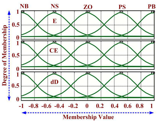
Figure 5.
Employed membership values.
Table 3.
ABC-FPA Parameters.
- = Membership function of P fuzzy set in X Universe of discourse
- = Membership function of Q fuzzy set in Y Universe of discourse
- x, y variables defined in Universe X and Y, respectively
Output D is calculated as:
where,
- = Crisp output
- = Membership function (Aggregated)
- D = Fuzzy output
- S = Subarea/Universe of discourse
Also, neural-fuzzy network output () expressed mathematically as:
where,
- = Membership function of fuzzy set A in E universe of discourse
- = Membership function of fuzzy set B in dE universe of discourse
- WLi = Weight of consequent ith layer
The ANFIS objective function is expressed mathematically as:
where,
- P = Total sample
- D = Fuzzy output
- = Neural network output
Rule I: Biotic pollination uses levy flight for transferring pollens and is called global pollination in which the ith pollen solution vector is expressed mathematically using Equation (12). The Levy flight factor is accountable for pollens transport which improves the methodology of pollination where scaling factor is responsible to limit step size.
where,
- = Vector representing solution
- T = No. of iteration
- Lf = Levy flight factor
- = Scaling factor
- Gbest = Global best solution
Rule II: Self-pollination is termed as local pollination and characterized mathematically as:
- and = two unlike pollen in the species
- Pf = Switched probability
Rule III: The performance of the flower is assumed to be identical to the probability of reproduction which is equivalent to resemblance of two concerned flowers.
Rule IV: Pollination is interchanged between global and local, which depends on switching probability which lies between 0 and 1.
The proposed nature-inspired FPA algorithms are responsible for providing proper learning of the neural network to reduce root mean square error between outcomes of D(Fuzzy output) and (Neural network output). Pollen position (duty ratio) is updated using biotic/abiotic pollination for the next iteration. Under step variation in solar insolation, the corresponding variance in voltage/current threshold is expressed mathematically as [22]:
where,
- =nth iteration PV voltage
- =nth iteration PV current
- = change in PV voltage (nth and (n − 1)th iteration)
2.4. Electronic BLDC Commutator and VSI Switching
Commutation in Permanent Magnet DC Motor (PMDC) is obtained by a commutator and brushes. Nevertheless, hall sensors are important components employed in BLDC motors which sense the position of a rotor as the commutation wave. Coils and permanent magnets are employed as stator and rotor respectively, in which stator’s magnetic field rotates the rotor. Armature of a BLDC motor consists of a permanent magnet as a substitute of the coil which does not require brushes. Figure 6 demonstrates BLDC-driven structure with induced EMF and reference current. The electronic commutation process is used to control the VSI-employed BLDC motor in which winding current is adjusted with the help of decoder in proper sequence. In this method, symmetrical DC currents are situated in the phase voltage at 120°. Based on the motor alignment, the hall sensors produce signals of 60° phase difference. The gating signal for 3-phase VSI generated by transforming hall signals using the decoder is illustrated in Figure 7. The pulse width modulated pulses are generated by comparing triangular signal with duty cycle produced through MPPT. Table 4 portrays Hall signals and Switching states of BLDC used with electronic commutation. The high-frequency PWM pulses and six fundamental signals are operated with an AND gate, which produces 6 gating pulses for VSI inverter. As the atmospheric conditions change, the duty cycle is also regulated using MPPT methods which control the VSI and finally the BLDC motor is adjusted accordingly.
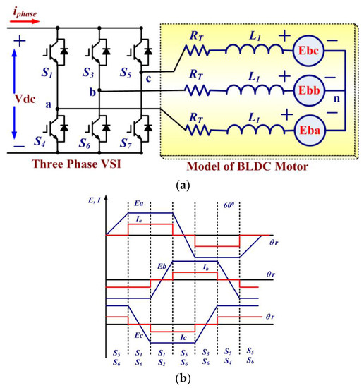
Figure 6.
(a) BLDC driven structure (b) induced EMF and reference current.
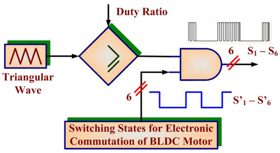
Figure 7.
Gating signal for 3-phase VSI.
Table 4.
Hall signals and Switching states.
The BLDC motor is analyses mathematically as [27]:
Developed electromagnetic torque () by BLDC motor can be expressed mathematically as:
where,
- Vap, Vbp, Vcp = Phase voltage of a 3-Phase BLDC motor
- Iap, Ibp, Icp = Phase Currents
- Eba, Ebb, Ebc = Phase Back EMF of BLDC motor
- L1 = Each Phase self-inductance
- M1 = Two phase’s mutual inductance
- TEM = Developed Electromagnetic torque of BLDC motor
- ωRotor = Rotor Speed
3. Experimental Results
Performance justification of the BLDC-driven PV pumping-employed Luo converter has been done through the dSPACE controller. For the purposes of MPPT operation, LA-55/LV-25 as current/voltage sensors are employed during practical implementation. Figure 8 portrays the BLDC-driven Luo converter-employed PV-pumping hardware developed in the laboratory. With the help of an A/D converter, analog pulses are transformed to digital and fed to the dSPACE interface. Electronic commutation/controlling BLDC has been executed by obtaining hall pulses from the input/output terminal and then generated pulses are outturned to the inverter.

Figure 8.
BLDC-driven Luo converter-employed PV-pumping hardware.
3.1. Steady-State Performance
The experimental behaviors of the PV module and motor pumping system have been tested under steady-state condition of irradiance level 1000 W/m2. The proposed MPPT design technique is working effectively and tracks optimal power from PV module with unity duty cycle at 1000 W/m2 solar insolation level depicted in Figure 9. Practical results obtained for the BLDC-driven Luo converter-employed PV pumping are described in Figure 9a PVG at 1000 W/m2. (Figure 9b) BLDC performance at 1000 W/m2. (Figure 9c) generated hall sensor pulses at 1000 W/m2 (Figure 9d) switched and hall pulses at 1000 W/m2 (Figure 9e) BLDC performance at 300 W/m2 (Figure 9f) switched and hall pulses at 300 W/m2.The corresponding BLDC motor and torque (1500 rpm) has been demonstrated in Figure 9d presents the obtained hall sensor pulses with motor torque. The performance of the BLDC motor-pumping system has been evaluated with 300 W/m2 solar irradiance. The motor torque is experimentally obtained, which is sufficient to operate PV water pumping. Based on duty cycle generation using the MPPT algorithm, the corresponding hall signals have been generated to trigger six switches of the inverter.
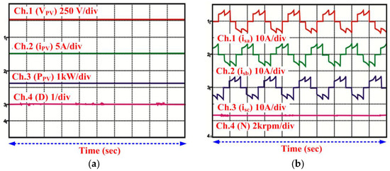
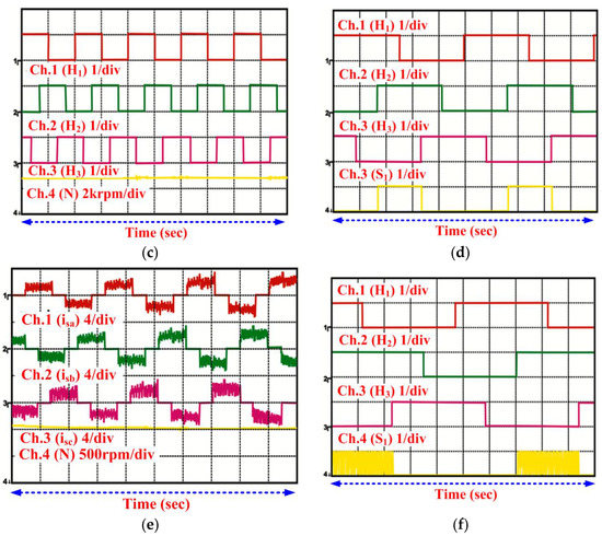
Figure 9.
BLDC-driven Luo converter-employed PV pumping (a) PVG at 1000 W/m2;(b) BLDC performance at 1000 W/m2; (c) generated hall sensor pulses at 1000 W/m2; (d) switched and hall pulses at 1000 W/m2; (e) BLDC performance at 300 W/m2; (f) switched and hall pulses at 300 W/m2.
3.2. Dynamic Behavior of PV System
The effective practice of recommended PV pumping system was proved under varying sun insolation levels. In this experiment, solar irradiance level is varied from 300 W/m2 to 1000 W/m2. According to variation in sun irradiance level, corresponding changes in PV current, DC link voltage, BLDC stator current and motor torque have been verified (Figure 10) and PV pumping is running without any interruption. The duty cycle for BLDC-PV pump control is generated with variation in sun insolation accordingly and outstanding motion control has been comprehended.
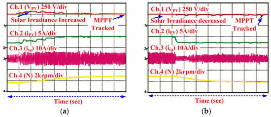
Figure 10.
BLDC-driven Luo converter (a) increased solar irradiance (b) decreased solar irradiance.
3.3. Behavior at Starting
Practical results found in Figure 11 interpret the safe starting of the BLDC motor under irradiance level 1000 W/m2 and 300 W/m2. Initially, the duty cycle is kept at 0.5 to run the motor. The sufficient motor speed is obtained by controlling the starting current, which runs the motor-pump system successfully. Figure 11 portrays the successful action of BLDC-PV pump at the start by limiting starting current, which reveals the progression with safe and soft start. The obtained results prove the more relevant performance conducted for the EMI reduction and soft starting for the experimental test conducted in [28].

Figure 11.
BLDC driven Luo converter employed PV pumping under soft starting (a) 1000 W/m2; (b) 400 W/m2
Table 5 portrays laboratory-adopted BLDC specification for a motion-controlled PV pump. Figure 12 interprets the existing global nature of the PV system under divergent sun radiation, which is demonstrated by the dark line. The operation begins with open-circuit voltage (VOPENCkt state) and reaches a global power point with variable solar irradiance. With application of hybrid ANFIS-FPA MPPT, steady GPP is attained over a complete day. The performance of the MPPT controllers for two algorithms ANFIS-FPA and FPA are tested with stepped irradiance input. Figure 13a illustrates that the proposed ANFIS-FPA imparts accurate and precise PV system outcomes with zero variation around GPP with fluctuating sun insolation. However, the FPA employed algorithm provides inconsistent and more oscillation nearby GPP that equates to the ANFIS-FPA algorithm described using Figure 13b. Under these situations, ANFIS-FPA has high tracked PV power with proportionately less GPP time. Practical results demonstrate that ANFIS-FPA algorithm contributes rapid and insignificant swinging differentiated with FPA MPPT illustrated in Figure 13a,b. Figure 14 demonstrates the behavior of numerous MPPT Viz. FPA, PSO, FLC and P and O control under standard test conditions. Under standard test conditions, ANFIS-FPA has better PV tracking efficiency compared to ANFIS-PSO, FLC and P and O methods, as illustrated with Figure 14. A hybrid ANFIS-FPA algorithm has global power point trajectory with the most tracked power and has zero oscillation throughout, equated with different controllers. The PV tracked trajectories are also examined under fluctuating weather situations (Figure 15). Under dynamic weather conditions, the PV tracking trajectory is found to be more accurate compared to conventional algorithms and has a zero GPP oscillation around this point, which is explained by Figure 15. Practical results reveal that ANFIS-FPA-optimized MPPT provides optimal tuning with high performance index.
Table 5.
Laboratory adopted BLDC specification.

Figure 12.
Existent global nature of PV system under divergent sun radiation.

Figure 13.
Behavior of MPPT under stepped irradiance (a) Hybrid ANFIS-FPA; (b) FPA.
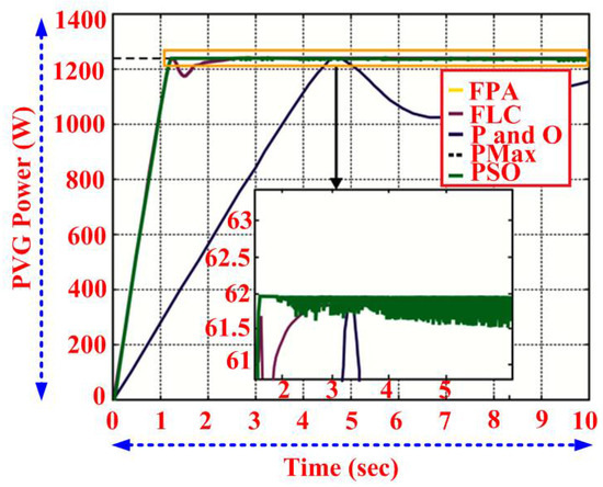
Figure 14.
Behavior of numerous MPPT control under standard test conditions.
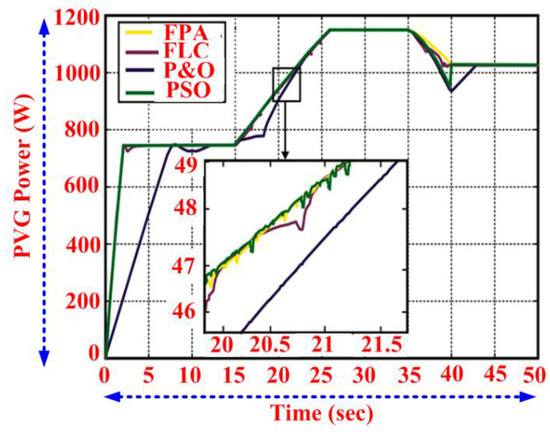
Figure 15.
PV tracked trajectories examined under fluctuating weather situations.
4. Conclusions
The Luo converter-based BLDC-driven PV pumping with ANFIS-FPA MPPT has been demonstrated under varying weather conditions using the dSPACE platform. The Luo converter has been proposed for desired GPP functions and is responsible for updating the duty ratio in each iteration using biotic/abiotic pollination. The PV-fed BLDC motor drive pumping system operates effectively under steady, dynamic states and soft-starting operating conditions, which have been validated through experimentally obtained responses. The enforcement of the ANFIS-FPA MPPT controller has been equated with the general P&O and ANFIS-PSO methods, which gives high tracking efficiency, fast design, and rapid convergence time under varying solar irradiance level. Performed experimental responses reveal that, compared to different bio-inspired, swarm-intelligence and classical MPPT techniques reviewed in literature, the ANFIS-FPA has superior power tracking ability, fast convergence velocity and accurate system response. The designed PV-based BLDC-driven pumping system provides the following functions viz. Luo converter-based MPPT tracking reducing switching losses based on electronic commutation/VSI switching, maintenance of the DC-link voltage, and BLDC motor speed regulation under low sun insolation, validated through practical responses using the dSPACE board.
Author Contributions
All authors contributed equally for the decimation of the research article in current form.
Conflicts of Interest
The authors declare no conflict of interest.
References
- Priyadarshi, N.; Sanjeevikumar, P.; Maroti, P.K.; Sharma, A. An Extensive Practical Investigation of FPSO based MPPT for Grid Integrated PV System under Variable Operating Conditions with Anti Islanding Protection. IEEE Syst. J. 2018. [Google Scholar] [CrossRef]
- Lakshman, N.P.; Palanisamy, K.; Babu, N.M.; Sanjeevikumar, P. Photovoltaic- STATCOM with Low Voltage Ride-Through Strategy and Power Quality Enhancement in Grid Integrated Wind-PV System. Electronics 2018, 7, 51. [Google Scholar]
- Jain, S.; Ramulu, C.; Sanjeevikumar, P.; Ojo, O.; Ertas, A.H. Dual MPPT Algorithm for Dual PV Source Fed Open-End Winding Induction Motor Drive for Pumping Application. Eng. Sci. Technol. 2016, 19, 1771–1780. [Google Scholar] [CrossRef]
- Kumar, R.; Singh, B. BLDC Motor Driven Solar PV Array Fed Water Pumping System Employing Zeta Converter. IEEE Trans. Ind. Appl. 2016, 52, 2315–2322. [Google Scholar] [CrossRef]
- Montorfano, M.; Sbarbaro, D.; Mor’an, L. Economic and technical evaluation of solar assisted water pump stations for mining applications: A case of study. IEEE Trans. Ind. Appl. 2016, 52, 4454–4459. [Google Scholar] [CrossRef]
- Alghuwainem, S.M. Speed Control of a PV Powered DC Motor Driving a Self- Excited 3-Phase Induction Generator for Maximum Utilization Efficiency. IEEE Trans. Energy Convers. 1996, 11, 768–773. [Google Scholar] [CrossRef]
- Jain, S.; Thopukara, A.K.; Karampuri, R.; Somasekhar, V.T. A Single-Stage Photo Voltaic System for a Dual- Inverter fed Open-End Winding Induction Motor Drive for Pumping Applications. IEEE Trans. Power Electron. 2015, 30, 4809–4818. [Google Scholar] [CrossRef]
- Sashidhar, S.; Fernandes, B.G. A Novel Ferrite SMDS Spoke-Type BLDC Motor for PV Bore-Well Submersible Water Pumps. IEEE Trans. Power Electron. 2017, 64, 104–114. [Google Scholar] [CrossRef]
- Killi, M.; Samanta, S. An Adaptive Voltage Sensor Based MPPT for Photovoltaic Systems with SEPIC Converter including Steady State and Drift Analysis. IEEE Trans. Power Electron. 2015, 62, 7609–7619. [Google Scholar] [CrossRef]
- Priyadarshi, N.; Kumar, V.; Yadav, K.; Vardia, M. An Experimental Study on Zeta buck-boost converter for Application in PV system. In Handbook of Distributed Generation; Springer: Cham, Switzerland, 2017; pp. 393–406. [Google Scholar]
- Priyadarshi, N.; Anand, A.; Sharma, A.K.; Azam, F.; Singh, V.K.; Sinha, R.K. An Experimental Implementation and Testing of GA based Maximum Power Point Tracking for PV System under Varying Ambient Conditions Using dSPACE DS 1104 Controller. Int. J. Renew. Energy Res. 2017, 7, 255–265. [Google Scholar]
- Kumar, N.; Hussain, I.; Singh, B.; Panigrahi, B.K. Framework of Maximum Power Extraction from Solar PV Panel using Self Predictive Perturb and Observe Algorithm. IEEE Trans. Sustain. Energy 2017, 9, 895–903. [Google Scholar] [CrossRef]
- Elgendy, M.A.; Zahawi, B.; Atkinson, D.J. Assessment of the Incremental Conductance Maximum Power Point Tracking Algorithm. IEEE Trans. Sustain. Energy 2013, 4, 108–117. [Google Scholar] [CrossRef]
- Zamora, A.C.; Vazquez, G.; Sosa, J.M.; Rodriguez, P.R.M.; Juarez, M.A. Efficiency Based Comparative Analysis of Selected Classical MPPT Methods. In Proceedings of the IEEE International Autumn Meeting on Power, Electronics and Computing, Ixtapa, Mexico, 8–10 November 2017; pp. 1–6. [Google Scholar]
- Abu-Rub, H.; Iqbal, A.; Ahmed, SK.M.; Peng, F.Z.; Li, Y.; Baoming, G. Quasi-Z-Source Inverter-Based Photovoltaic Generation System With Maximum Power Tracking Control Using ANFIS. IEEE Trans. Sustain. Energy 2013, 4, 11–20. [Google Scholar] [CrossRef]
- Mohamed, A.A.S.; Berzoy, A.; Mohammed, O. Design and Hardware Implementation of FL-MPPT Control of PV Systems Based on GA and Small-Signal Analysis. IEEE Trans. Sustain. Energy 2017, 8, 279–290. [Google Scholar] [CrossRef]
- Wang, L.; Singh, C. Population-Based Intelligent Search in Reliability Evaluation of Generation Systems with Wind Power Penetration. IEEE Trans. Power Syst. 2008, 23, 1336–1345. [Google Scholar] [CrossRef]
- Koad, R.B.A.; Zobaa, A.F.; El-Shahat, A. A Novel MPPT Algorithm Based on Particle Swarm Optimisation for Photovoltaic Systems. IEEE Trans. Sustain. Energy 2017, 8, 468–476. [Google Scholar] [CrossRef]
- Priyadarshi, N.; Sharma, A.K.; Azam, F. A Hybrid Firefly-Asymmetrical Fuzzy Logic Controller based MPPT for PV-Wind-Fuel Grid Integration. Int. J. Renew. Energy Res. 2017, 7, 1546–1560. [Google Scholar]
- Sundareswaran, K.; Sankar, P.; Nayak, P.S.R.; Simon, S.P.; Palani, S. Enhanced Energy Output From a PV System Under Partial Shaded Conditions Through Artificial Bee Colony. IEEE Trans. Sustain. Energy 2015, 6, 198–209. [Google Scholar] [CrossRef]
- Kalaam, R.N.; Muyeen, S.M.; Al-Durra, A.; Hasanien, H.N.; Al-Wahedi, K. Optimisation of controller parameters for grid tied photovoltaic system at faulty network using artificial neural network-based cuckoo search algorithm. IET Renew. Power Gen. 2017, 11, 1517–1526. [Google Scholar] [CrossRef]
- Ram, J.P.; Rajasekar, N. A novel Flower Pollination based Global Maximum Power Point method for Solar Maximum Power Point Tracking. IEEE Trans. Power Electron. 2017, 32, 8486–8499. [Google Scholar]
- Abouzeid, M.; Sood, V.; Youssef, M. A Comparative Study of a PV-MPPT grid-integrated system under Different Control Techniques. In Proceedings of the IEEEElectrical Power and Energy Conference (EPEC), London, ON, Canada, 26–28 October 2015; pp. 256–261. [Google Scholar]
- Pansare, C.; Sharma, S.K.; Jain, C.; Saxena, R. Analysis of a Modified Positive Output Luo Converter and its application to Solar PV system. In Proceedings of the IEEE Industry Applications Society Annual Meeting, Cincinnati, OH, USA, 1–5 October 2017; pp. 1–6. [Google Scholar]
- Pachauri, R.K.; Chauhan, Y.K. Modeling and Simulation Analysis of PV Fed Cuk, Sepie, Zeta and Luo DC-DC Converter. In Proceedings of the IEEE1st International Conference on Power Electronics. Intelligent Control and Energy Systems (ICPEICES-2016), Delhi, India, 4–6 July 2016; pp. 1–6. [Google Scholar]
- Kaced, K.; Larbes, C.; Ait-Chikha, S.M.; Bounabi, M.; Dahmane, Z.E. FPGA implementation of PSO based MPPT for PV systems under partial shading conditions. In Proceedings of the IEEE6th International Conference on Systems and Control, Batna, Algeria, 7–9 May 2017; pp. 150–155. [Google Scholar]
- Niapoor, S.A.KH.M.; Danyali, S.; Sharifian, M.B.B. PV Power System Based MPPT Z-Source Inverter to Supply a Sensorless BLDC Motor. In Proceedings of the 1st Power Electronic & Drive Systems & Technologies Conference, Tehran, Iran, 17–18 February 2010; pp. 111–116. [Google Scholar]
- Saponara, S.; Gabriele, C.; Groza, V.Z. Design and Experimental Measurement of EMI Reduction Techniques for Integrated Switching DC/DC Converters. IEEE Can. J. Electr. Comput. Eng. 2017, 40, 116–127. [Google Scholar]
© 2018 by the authors. Licensee MDPI, Basel, Switzerland. This article is an open access article distributed under the terms and conditions of the Creative Commons Attribution (CC BY) license (http://creativecommons.org/licenses/by/4.0/).