Review

A Comprehensive Review of the Techniques on Regenerative Shock Absorber Systems

School of Engineering, RMIT University, Bundoora Campus, East, Corner Plenty Rd and McKimmies Rd, Bundoora, VIC 3083, Australia
*
Author to whom correspondence should be addressed.
Energies 2018, 11(5), 1167; https://doi.org/10.3390/en11051167
Submission received: 28 March 2018 / Revised: 21 April 2018 / Accepted: 3 May 2018 / Published: 7 May 2018

Abstract

:
In this paper, the current technologies of the regenerative shock absorber systems have been categorized and evaluated. Three drive modes of the regenerative shock absorber systems, namely the direct drive mode, the indirect drive mode and hybrid drive mode are reviewed for their readiness to be implemented. The damping performances of the three different modes are listed and compared. Electrical circuit and control algorithms have also been evaluated to maximize the power output and to deliver the premium ride comfort and handling performance. Different types of parameterized road excitations have been applied to vehicle suspension systems to investigate the performance of the regenerative shock absorbers. The potential of incorporating nonlinearity into the regenerative shock absorber design analysis is discussed. The research gaps for the comparison of the different drive modes and the nonlinearity analysis of the regenerative shock absorbers are identified and, the corresponding research questions have been proposed for future work.

1. Introduction

Due to the growing number of vehicles over recent decades and the increase of clean energy demand, the energy dissipation of a vehicle on different parts has been investigated. Recently, regenerative shock absorber systems caught the attention of many researchers because of the capability to harvest dissipated energy, due to its feasibility and accessibility. The fuel energy consumption of a car was analysed by Lafarge, Cagin [1] who stated that the fuel energy dissipated to drive the wheels accounts for up to 22.5% of the total fuel energy consumed, which ranks it the second following engine heat losses of 75.2%. In reality, the percentage of the dissipated fuel energy on driving the wheels is expected to increase as a result of the uneven or rough road surfaces.
Unlike the conventional shock absorber which reduces the vibration through viscous damping and converts the kinetic energy into heat energy dissipated, the regenerative shock absorber converts the kinetic energy mainly into electrical energy. This harvested electrical energy can be stored in the battery for later use. According to Zuo, Scully [2], automobiles contribute 70% of the carbon monoxide, 45% of the nitrogen oxide and 34% of the hydrocarbon pollution throughout the United States. One of the benefits brought by the regenerative shock absorber is that it can extend the mileage of the vehicle by saving petroleum fuel or electrical energy to achieve a reduction in the greenhouse gas emission.
In addition, the regenerative shock absorber can operate as a part of the active suspension system in order to improve the ride and comfort performance [3,4,5,6,7]. Proportional–integral–derivative control is commonly used in these applications for obtaining stable output power or reducing vibrations [8,9]. Based on the conservation of energy principle, better ride and comfort performance resulting from less kinetic energy or less vibration energy of the suspension system yields less amount of harvested energy. This contradiction can be overcome by adopting the control system which can make a compromise for both the energy harvesting and ride and comfort performances. One good concept proposed by Elliott and Zilletti [10] was to utilize the electromagnetic transducer as either a shunt damper or an energy harvester. Therefore, the system can be switched between the different functionalities for desired performance output. It was also shown in their results that the coupling coefficient increased with the size of the electromagnetic transducer, meaning that the mechanism combining the shunt damper and energy harvester can operate well especially in the large-scale transducer such as a regenerative shock absorber.
The future trends of the regenerative shock absorber would be:
  • High power to weight ratio
  • Better mechanical-electrical energy conversion efficiency
  • High compatibility with the vehicle.
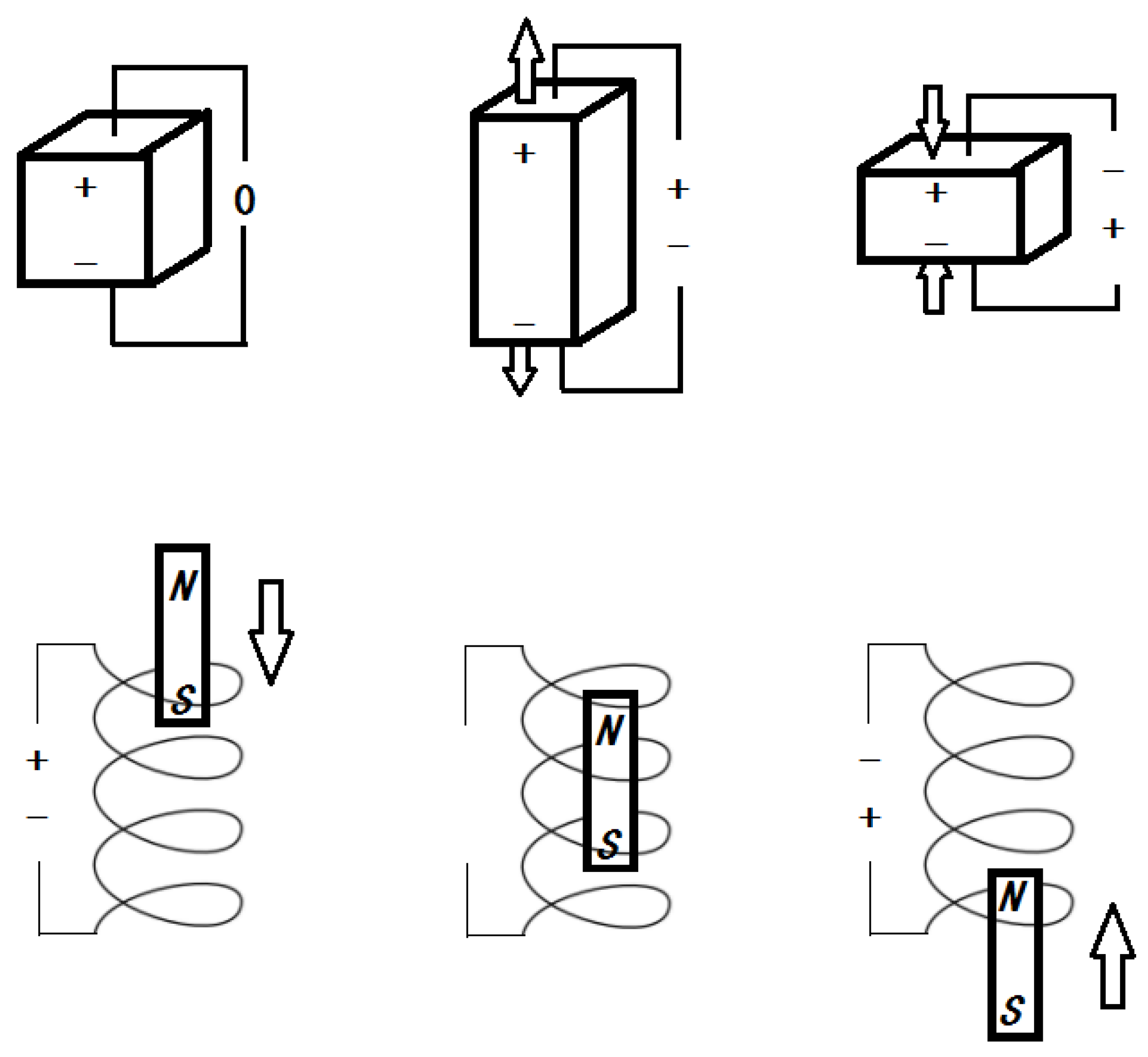
Among the methods in which the kinetic energy was converted into electrical energy, as shown in Figure 1, the use of the piezoelectric material and electromagnetic generator were frequently discussed because of their outstanding compatibilities and high efficiencies. Xiao, Wang [
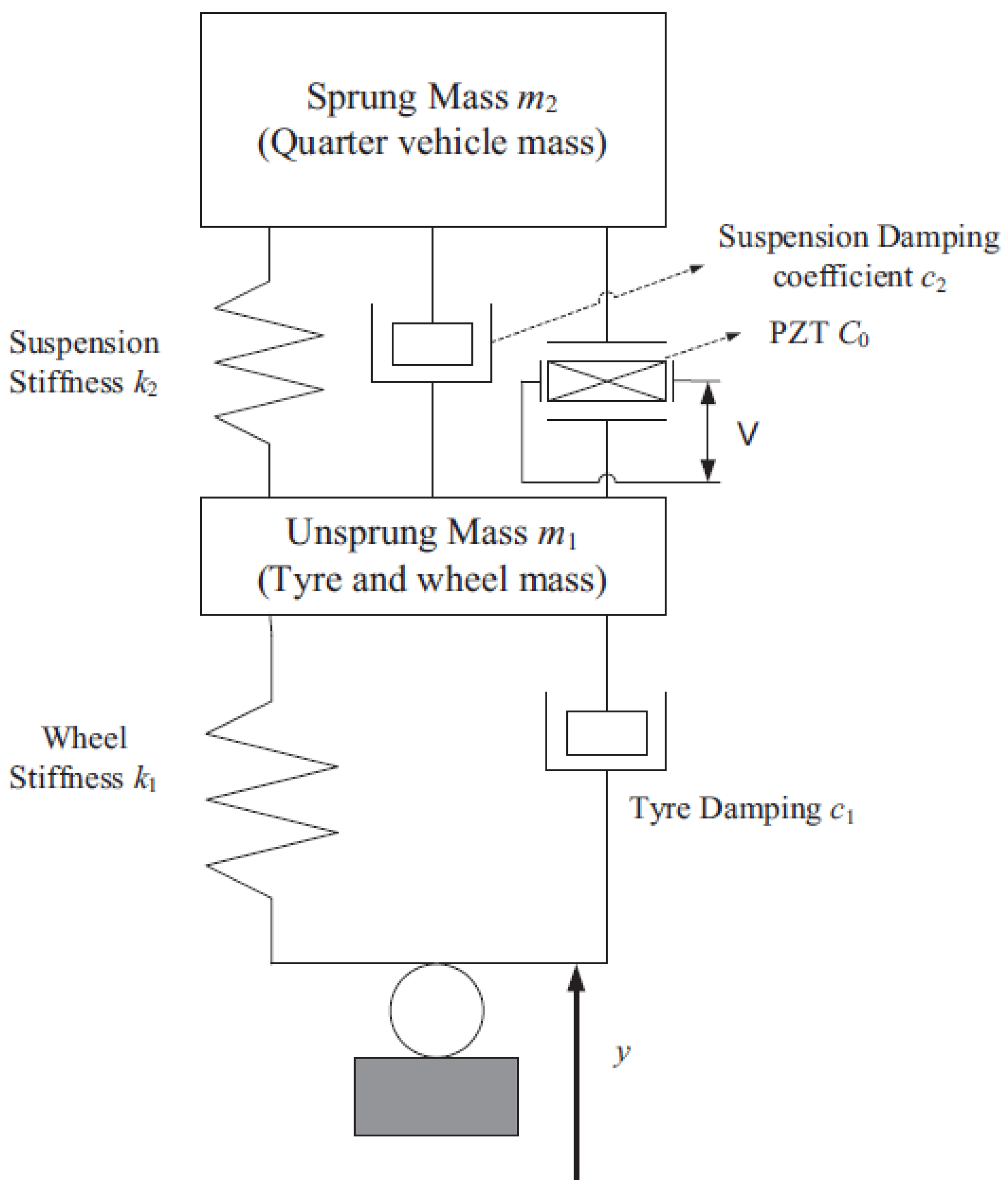
11] discussed the feasibility of having the piezoelectric (PZT) generator in 2 degrees of freedom (2DOF) quarter vehicle suspension system as an additional energy harvesting element, as shown in Figure 2. It was found that the improvement of the resonant power output of the 2DOF piezoelectric system only and largely depends on the cabin mass to tyre mass ratio and suspension stiffness to tyre stiffness ratio.
Lee, Jang [12] combined the piezoelectric transducers with a shock absorber to generate electricity from the fluid pressure change induced by the piston displacement. Xie and Wang [13] discussed the effect of the dimension of the piezoelectric plate, input velocity and road roughness. Piezoelectric transduction was better than electromagnetic and electrostatic transduction for relatively high power density [14]. It also had the advantages of the compact size and easy implementation [15]. However, for the applications where larger displacement was most involved, the advantages of the piezoelectric transduction were compromised.
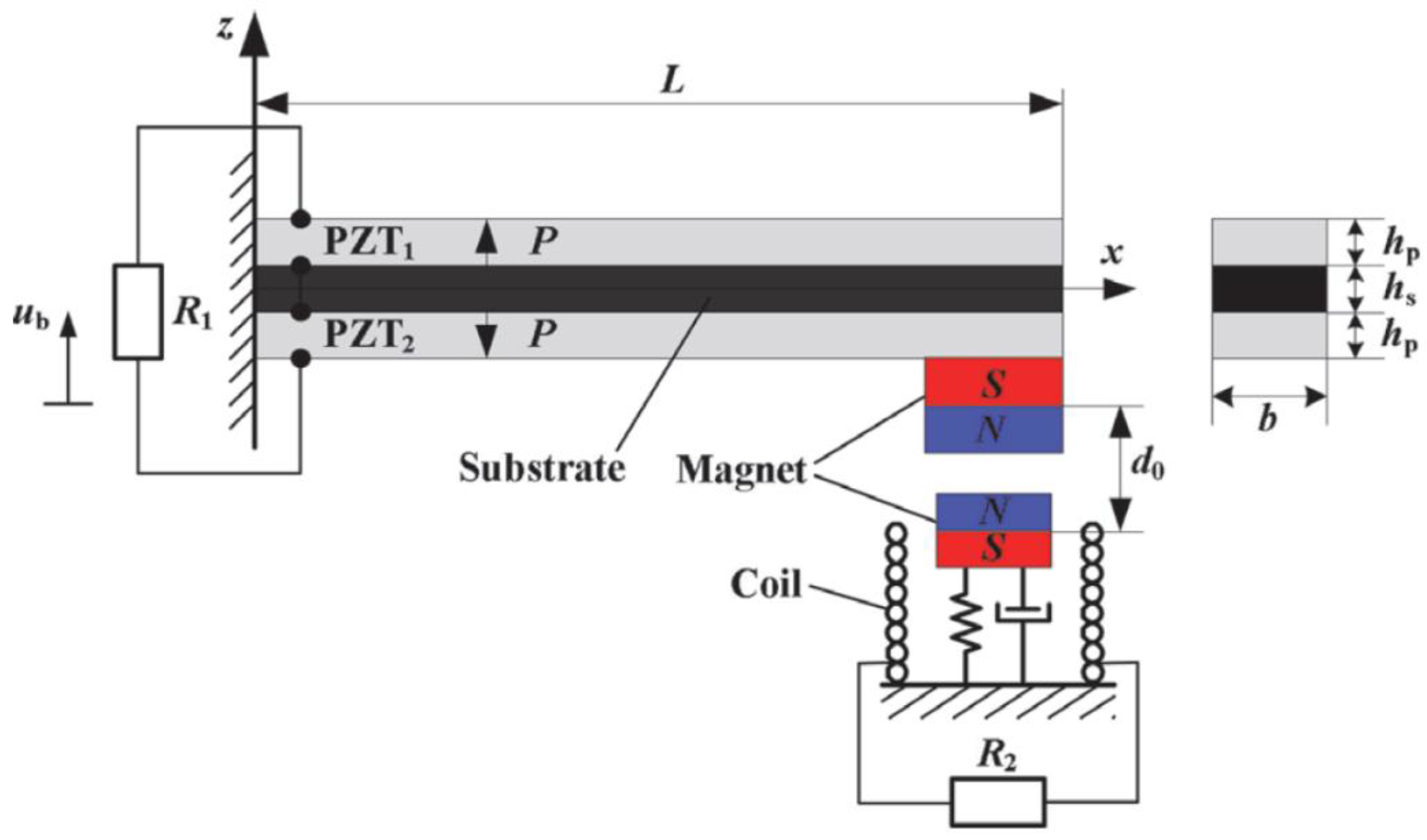
Xu, Shan [16] proposed a hybrid energy harvester that combines both the piezoelectric and electromagnetic transducers, as shown in Figure 3:
The results show that this combined mechanism was able to broaden the bandwidth and increase the output power, thus it was superior to any of the single mechanisms. It was proven that it inherited the advantage of high power density from the piezoelectric transduction and simultaneously it operated well under the low frequency excitation like an electromagnetic transducer.
Poulin, Sarraute [17] constructed the equivalent impedance models to compare between two electromechanical systems. It was also concluded in the study that the piezoelectric system has higher power density than the electromagnetic system and thus is more suitable to microsystems. The comparison results are listed in Table 1 below.
A typical shock absorber on a commercial vehicle needs to be reliable and able to operate in the frequency range of 1–30 Hz and with a maximum shock displacement of 0.1 m. It can be seen from Table 1 that in a regenerative shock absorber the electromagnetic transducer can outperform the piezoelectric transducer due to lower strain, low resonant frequency and higher displacement.
Mitcheson, Reilly [18] compared different transducer technologies and it was found that when the generator size increases, piezoelectric transducer gradually loses its advantage over electromagnetic transducer in the high frequency range. Similar conclusion was drawn by Elliott and Zilletti [10], the increased size of the transducer does not improve the performance of the piezoelectric transducer, however it can improve the performance of the electromagnetic transducer. Therefore, more studies have been focused on the electromagnetic system as it is more feasible considering the modal resonant frequency of the vehicle, displacement of the shock absorber and its packaging size. In addition, compared with piezoelectric transduction, electromagnetic transduction is more reliable and cost friendly.
The power output of the electromagnetic energy harvesting system depends on total resistance and voltage output which, according to Faraday’s law of induction, can be expressed by:
U = B l v
where B is the magnetic field intensity, l is the total coil length and v is the coil speed with respect to magnets.
Therefore, the increase of the system power output can be realized through the improvement of the coil and magnet arrangement and configuration or the amplification of the coil speed with respect to magnets. These are two main focuses of the recent development innovations for the electromagnetic regenerative shock absorbers.
The direct drive system has the magnets and coils directly attached to the vehicle body and wheel assembly, respectively. When subjected to the reciprocating movement due to the road unevenness, the relative motion between the magnets and coil generates electricity as a result of the direct attachment to the oscillators. Therefore, the coil speed with respect to the magnets strictly depends on the relative speed between the vehicle cabin and wheel. The relative speed depends on the driving speeds of the vehicle and road profiles. As a result, only the electromagnetic constant Bl can be designed, changed and optimized to increase the power output.
Instead of increasing the electromagnetic constant Bl of the direct drive system, an indirect drive system relies on the speed amplifying mechanism which can increase the coil speed with respect to the magnets. Most regenerative shock absorber can be categorized into these two drive modes for adaption with the requirements of energy harvesting and vibration control.
For the direct drive system, the efforts were most focused on finding the optimum magnet arrangement with a higher flux gradient per unit mass [19,20,21], as well as the optimum coil profile [22] and the optimum mass distribution of the transducer [23]. However, their feasibility for application as the shock absorber is still undetermined. Whereas for the indirect drive system, questions have been raised on maintaining the ride comfort and road handling ability since it is the main function of the shock absorber, therefore the compatibility of the indirect drive regenerative shock absorber onto the vehicle would also be focused in the future.
Many innovative designs including different types of the transducers had been proposed, such as piezoelectric and electromagnetic transducers which includes magnetorheological, hydraulic and pneumatic drive systems [24,25,26,27,28]. Each of these types had its own advantages and disadvantages and was only applicable in certain applications. Due to the packaging size and mass restrictions of the shock absorber, the transducers are hard to be fairly compared to determine which type is most suitable for the application of the shock absorbers.
In order to maximize the energy harvesting efficiency, further investigations have been conducted on the electrical circuits and control algorithms. Because of the variation of the transducers utilized in the harvester, different electrical circuits and control algorithms may not work equally well.
This paper reviews the recent technologies of the regenerative shock absorber. The highlight of this paper is to categorize the regenerative shock absorbers based on their drive modes and study the associated damping performance, energy harvesting efficiency, electrical circuit and control algorithm. Each of these aspects will be summarized in the tables. The excitation input of the regenerative shock absorber will be applied as sinusoidal, step and random inputs. The possibility and potential of the nonlinear regenerative shock absorber will be discussed. Lastly, the future research direction of the regenerative shock absorber design will be discussed based on the research gaps. This paper aims to review the up to date techniques involved in the regenerative shock absorber design and closing the research gaps identified to pave the way for the future study.

2. Direct Drive Regenerative Shock Absorber Systems and Technologies

A direct drive system has attracted substantial amount of interests due to its compact design and simple manufacturing. Zuo, Scully [2] proposed a 1:2 scale linear regenerative shock absorber system with longitudinal magnet arrangement patterns. Also, an aluminum center rod and steel outer shell was added to increase the magnetic field intensity. This prototype was able to produce 2–8 W power and it was found that more power can be harvested at the modal resonant frequencies.

2.1. Magnet Arrangement Pattern Design

In order to further increase the magnetic field intensity for high output power, different magnet patterns were proposed. One of the easiest ways is to double the number of the magnets, resulting in more magnetic flux lines that can be trapped in between two layers of magnets where the coils are wired, thus increasing the output voltage. Many researchers have adopted this way in their designs as it is efficient and simple to build [29,30,31].
It is also shown in Figure 4 that in a magnet stack, the magnets are not placed right next to each other, instead they are separated by spacers. The same layout was adopted by Cheung [32] who proposed a magnet sliding tube designed for harvesting wave energy where the net flux density in the spacer area between two opposing polarity magnets is zero due to the complete flux cancellation as shown in Figure 5 where Case A represents the separation, in this case, flux cancellation did not take place due to the short ranged magnetic potential, the behavior was just the sum of two isolated single magnets. Cases B and C represent the separation decreased, in these cases, the flux cancellation effect became more prominent and the amount of captured energy increased accordingly to reach a maximum at a gap of about 1/3 of the magnet length. The captured energy in this case increased by 60%. However, the two side peaks remained nearly unchanged because of the end effect. As the thickness of the spacer gradually decreases (from A to C), the effect of the flux cancellation decreases and the captured energy reaches the maximum when the spacer had the same thickness of a magnet. As a result, the captured energy can be increased by 60%. The same result was obtained by Ebrahimi, Bolandhemmat [30] who concluded that magnet stack can yield the highest output power with spacers of equal thickness.
The main limit involved in using two layers of magnets or spaced magnets is the problem of the extra weight. The excessive weight will result in more fuel consumption, which is contradictory to the original purpose of the regenerative shock absorber.
The magnetic arrangement pattern of the Halbach array was studied by many researchers for its high weighted magnetic flux density compared with other magnet arrangement patterns. As shown in the Figure 6, by turning the polarity orientation of the magnets 90 degree each time to form a Halbach array, the magnetic flux lines can be accumulated on one side of the Halbach array that is close to the coils, leaving nearly zero magnetic field intensity on the other side of the Halbach array. How Halbach array can actually affect the energy harvesting performance of a regenerative shock absorber system was investigated by Zhang [33]. He discovered that the Halbach array has the highest magnetic flex density compared to the conventional longitudinal and transverse magnet polarity orientation layouts with or without the spacer shown in Figure 7, because the radial magnets in Halbach array arrangement perform better than the other magnet arrangement in achieving the high magnetic flux density.
Zhu, Beeby [35] designed a vibrational energy harvester using the magnet arrangement pattern of the Halbach array and compare the Halbach array with 4 other different magnet arrangement patterns shown in Figure 8. It was found that the magnetic field strength in the Halbach array is highest among all the magnet arrangement patterns. However, the voltage output of the Halbach array pattern with spacers is greater than that of layout (a) and (b) but almost 10 times smaller than layout (c) and (d). This is because although the Halbach array has a stronger magnetic field, its magnetic flux gradient is lower than that in (c) and (d). Therefore, it should be realized that the Halbach array may not be the solution for all the problems in question and reducing the thickness of magnets can lead to better results. But in the research, longitudinally arranged polarity orientation of the magnets was not taken into consideration, thus the most efficient magnetic arrangement was still unclear.
The use of the Halbach array magnet arrangement pattern can also be helpful in obtaining the enhanced dynamics. Long, He [36] designed a suspension system utilizing the magnets arranged in Halbach array to obtain a good damping performance. It has been experimentally validated that the Halbach array with a controller can improve the system stability. Some researchers combined the two above-mentioned methods and proposed the double layers of the Halbach array magnet arrangement [31,35,37,38,39,40].

2.2. Coil Design

Regardless of which magnetic pattern is being used in the regenerative shock absorber, some studies suggested designing the coil based on the magnet arrangement. Tang, Lin [31] proposed to use a four-phase coil in one magnetic cycle, as shown in the Figure 9. The reason for that is shown in Figure 10 where higher normalized power can be obtained with higher coil phase number. More electromotive potential would be cancelled out if less coil phases are adopted.
The coil profile was investigated by Elvin and Elvin [41] on the effect of the number of coil layers, coil resistance and gauge numbers. The results showed that with more number of layers more energy can be generated until it reaches its limit where too much energy begins to be dissipated due to the resistance of the extensive coil. Also, the use of a coil with less gauge number will not yield higher voltage but it has the commercial benefits and takes up less space. Different coil phase designs can also affect the system resonant frequency and the quality factor, resulting in the difference in system damping. This phenomenon can be found in the research conducted by Zuo, Scully [2] where 90 degree phase coil presents higher quality factor than 0 degree phase coil set, thus the electromagnetically induced damping on 90 degree phase coil set is lower. Quality factor can be important in evaluating the effect of the magnet coil combination on the energy harvesting efficiency since its influence on the system damping and power output cannot be ignored.
Different regenerative shock absorbers with the direct drive systems have been summarized below in Table 2.

3. In-Direct Drive Regenerative Shock Absorber Systems and Its Technologies

Due to the weight limit of the magnets and coils, many attempts have been made to increase the coil speed with respect to the magnets.
The in-direct drive regenerative shock absorber system does not transfer the road excitation directly into the linear motion between the translator and the stator. Instead, it amplifies the input excitation through a variety of mechanisms and converts the linear motion mostly into a rotational motion. Many types of mechanisms that have been proposed include: the ball screw mechanism, rack and pinion mechanism, hydraulic mechanism, pneumatic mechanism and their variants. Among these mechanisms, the ball screw, rack and pinion and their variants can be regarded as mechanical motion rectifier due to the mechanical mechanism related working principle. The devices that utilize the hydraulic system or pneumatic system to deliver motion conversion and velocity amplification can be regarded as a fluid motion rectifier.

3.1. Mechanical Motion Rectifier

Li, Zuo [47] proposed an innovative motion rectifier system, which can convert the up and down movement of the shock absorber into unidirectional rotation of the generator, shown in the Figure 11. The rack and pinion mechanism helps to convert and amplify the excitation displacement. The bidirectional linear motion to unidirectional rotation rectification is accomplished with the bevel gear and clutch. The experiments and simulations were carried out by the researchers and it showed that the prototype achieved over a high efficiency of 60% and 15 W power output was obtained when the vehicle is driven at a speed of 15 mph. Further investigation was conducted by Li and Zuo [48] to evaluate the performance of the prototype. A quarter car suspension model was constructed to simulate the situation where vehicle was driven on the ISO Class C road. It was found that the motion rectifier can achieve the road comfort and the road handling on a conventional vehicle. 60–84 W can be harvested from a quarter car regenerative suspension with the motion rectifier when travelling at 67.5 mph, which is more than that from the quarter car regenerative suspension without the motion rectifier.
Zhang, Zhang [49] and Guo, Liu [50] optimized the mechanical motion rectifier by proposing the dual overrunning clutch system. Two sets of racks and pinions and the 2 overrunning clutches attached allow the excitation amplification and motion rectification to occur simultaneously with limited space provided. The shaft rotates in one direction and drives the DC generator for power generation. The working principle is shown in Figure 12. The generated power was stored in the capacitor for other application. The fabricated prototype generated 4.302 W at 2.5 Hz with the excitation displacement amplitude of 7.5 mm. Additionally, the damping performance can be changed by adjusting the external load electric resistance.
Another interesting design was proposed by Xie, Li [51]. Unlike other rack pinion system where the electrical generator provides the damping force, this design utilizes the traditional viscous damper in parallel with the secondary rack and pinions at the bottom, to provide damping and harvest energy. Considering the packaging size, however, this layout may not be feasible in a real application.
Ball screw mechanism was introduced as an alternative by many researchers [52,53,54,55,56], the schematic is shown in Figure 13. Similar to the rack and pinion system, it also converts the up and down motion into a rotational motion through a ball screw spinning along the thread. Due to the up and down movement of the shock absorber, the converted rotational motion is bidirectional and needs rectification as well. Zhang, Huang [57] incorporated the ball-screw mechanism and DC brushless motor into a regenerative shock absorber system. The experiment result showed that the maximum voltage of 17.5 V can be generated under the sine wave road input. Because of the low voltage, a condenser is needed to charge the battery. It was also pointed out by the author that the ride and comfort performance cannot be guaranteed under a high frequency road excitation.
Another combined innovation on regenerative shock absorber was proposed by Liu, Xu [59] where a ball screw was installed for the conversion from the linear to rotary motion and two overrunning clutches were used for the rectification from the bidirectional to unidirectional motion, as shown in Figure 14. The input velocity amplification factor can be adjusted through a ball screw mechanism and kinetic energy can be harvested throughout the whole reciprocating motion of the shock body. The experimental results indicate that an average power output of 24.7 W can be harvested over an 8 s period, and the adjustable damping coefficient can be maintained close to the damping coefficient of the passenger vehicle shock absorbers.

3.2. Fluid Motion Rectifier

Instead of converting the linear motion into rotational motion mechanically, the hydraulic/pneumatic systems were introduced in many energy harvester designs for smoother operation and less mechanical friction energy dissipation [27,60,61,62,63,64,65,66]. Like the other indirect drive regenerative shock absorber systems where the stroke velocity is amplified mechanically, the smoother operation and the motion rectification can be delivered simultaneously in the hydraulic system. Among all these innovations, Fang, Guo [67] developed an actively controlled hydraulic suspension system by using an oil pump to generate hydraulic pressure in the shock absorbers, as shown in Figure 15. The system had one-way check valves to control the direction of fluid flow, accelerometers in all four corners, and actuators and accumulators, to reduce the response time in the system and ensure that sufficient pressure is maintained in the system. Wang, Gu [68] proposed the similar hydraulic system with four check valves for flow rectification and found that the accumulators can be optimized to increase the power efficiency up to 40%.
The drawback of the hydraulic/pneumatic energy harvesting system is that the response time is delayed due to the flow rate and fluid compressibility, also, the rapture may lead to potential failure, resulting in an unreliable system that can cause accidents. To simplify the system, Galluzzi, Tonoli [69] developed a hydraulic regeneration system where check valves are placed inside the hydraulic piston to reduce the mechanical difficulty while amplifying the stroke velocity, as shown in Figure 16. The results show a 12% increase in harvested power over the regenerative shock absorber system without the proposed mechanical motion rectifier.
Pneumatic suspension system was adopted by many vehicles especially in off road applications [70] due to its high energy density which meets the space limitation [71], and its comfort and changeable damping performance [72]. It can be converted into a regenerative system with the additional energy converting elements [73]. Shaiju and Mitra [74] proposed the idea where the oscillating motion energy of the vehicle sprung mass could be captured and stored in the form of compressed air energy. The theoretical results also showed that the vehicle dynamics could be improved by the pneumatic suspension system through being integrated with the braking system. The pneumatic system operates in a similar way as the hydraulic system due to the similar flow property, many authors regarded them as the same system [30,75]. Due to the compressible nature of air, however to some extent, the pneumatic system performs differently from the hydraulic system. Therefore, evaluation of the energy harvesting performance of the pneumatic regenerative shock absorber is identified as a research gap because few people have worked on it. Different indirect drive regenerative shock absorber systems have been summarized below in Table 3.

4. Comparison between the Direct Drive System and Indirect Drive System

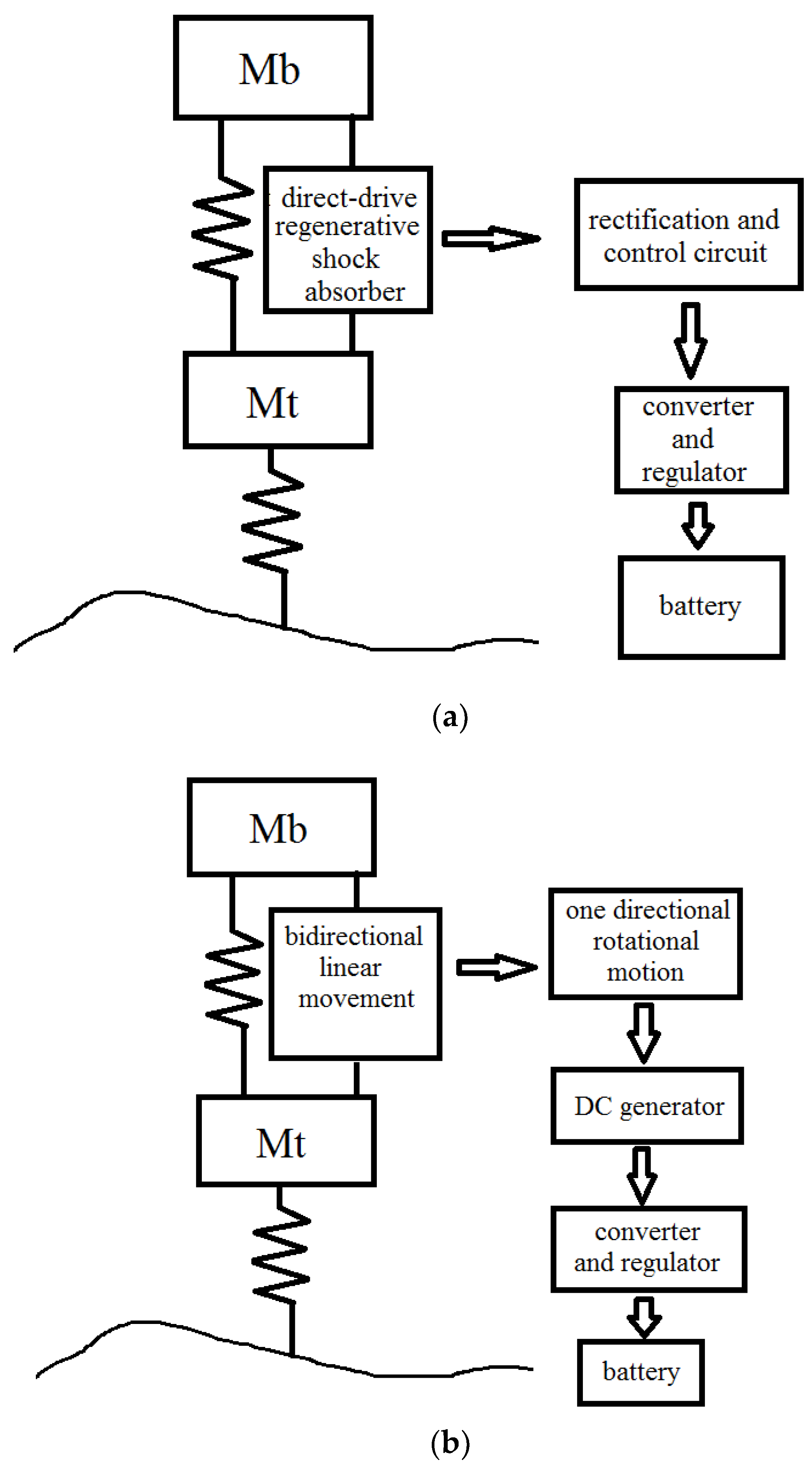
The regenerative shock absorber system can be divided into two main categories based on the drive mode. If the energy can be regenerated directly as a result of the linear movement between the two oscillators, namely the wheel assembly and the vehicle body, it can be categorized as the direct-drive regenerative shock absorber system. The other type, which is the indirect drive regenerative shock absorber system, relies on a certain mechanism to achieve the conversion between the linear motion of the shock absorber and the rotary motion of the generator. During this process the input speed can be amplified by the mechanism. The 2DOF lumped mass spring systems can be applied to represent the quarter car suspension systems with these two categories of the regenerative shock absorber systems, as shown in Figure 17.
Compared with the direct drive system, the indirect drive system has the following advantages:
  • The frequency, displacement and velocity amplitudes of the input excitation can be changed through the installed mechanism to achieve better energy harvesting and vehicle dynamics
  • The increase of the input excitation speed through the speed amplifying mechanism can eliminate the need for a strong magnetic field, therefore the number of magnets can be reduced and undesired additional weight can be minimized.
  • The layout of the system is more flexible as the mechanism of the indirect drive does not have to be inside the shock absorber.
In Figure 17, another noticeable difference between these two drive modes is that the direct drive system has the AC output and the indirect drive has the DC output. As a result, the voltage output of the direct drive system needs rectification before charging the battery whereas in the indirect drive system, the unidirectional rotation of the DC motor have a constant DC output thus the rectification process is not required. Regulation or dc-dc inverter is needed for both systems to maintain a steady constant voltage for effectively charging a battery.
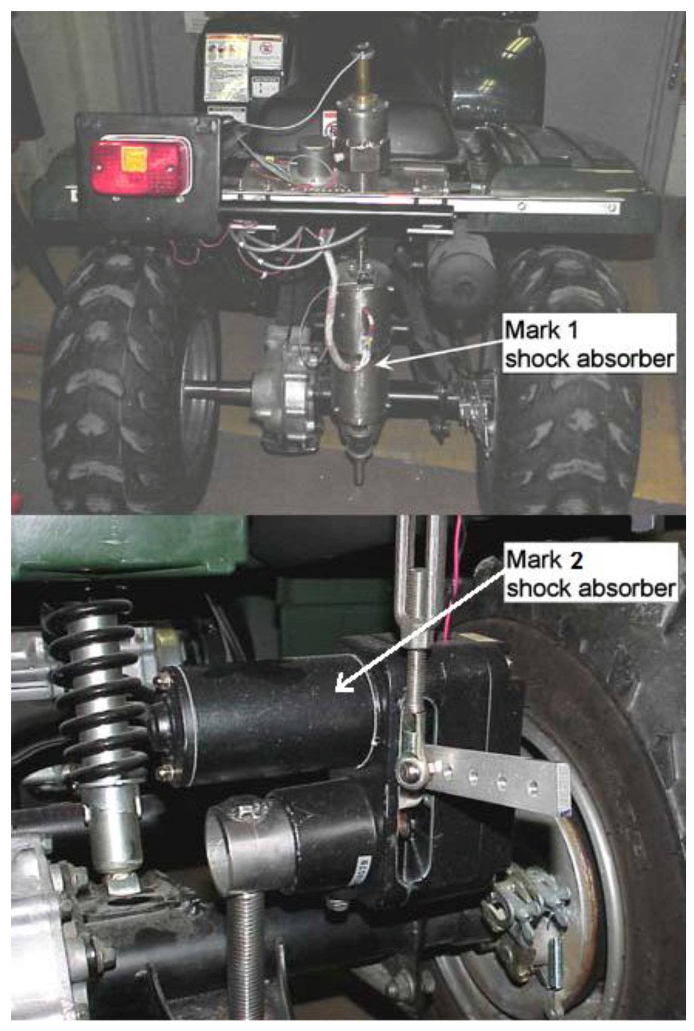
To compare the energy harvesting performance of the regenerative shock absorbers with different drive modes, Gupta, Jendrzejczyk [29] have both direct drive and indirect drive regenerative shock absorbers installed on an all-terrain vehicle (ATV) passing a wooden beam, shown in Figure 18. Mark 1 shock absorber is a direct drive linear electromagnetic generator with two layers of magnets and mark 2 is an indirect drive system with a lever arm that can convert the linear motion into rotary motion where the input speed is amplified 6 times. The results showed that when running over the wooden beam, direct drive system can generate 7.4 W while the indirect drive system can generate 88.8 W.
Even though the results indicated a considerable difference between the amounts of the harvested power, it cannot be concluded that the indirect drive system is more efficient than the direct drive system. In most of the papers that compare the drive modes, the generator configurations differ as the direct drive system has a linear generator and the indirect drive system has a rotary generator, hence the difference of the generator configurations results in the difference of the energy output. In addition, the damping coefficients of the regenerative shock absorbers and their effects on the vehicle dynamics should also be evaluated.
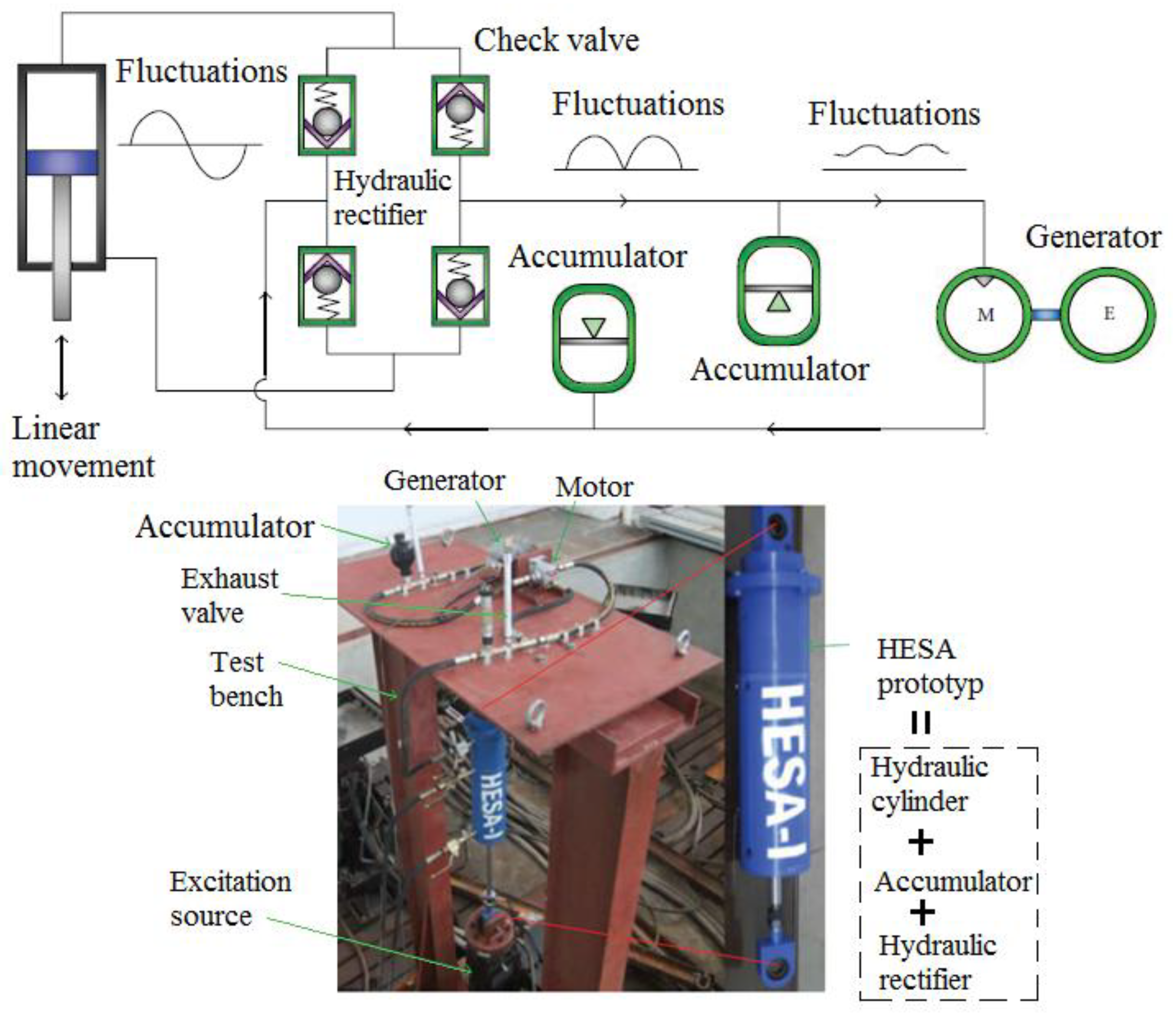
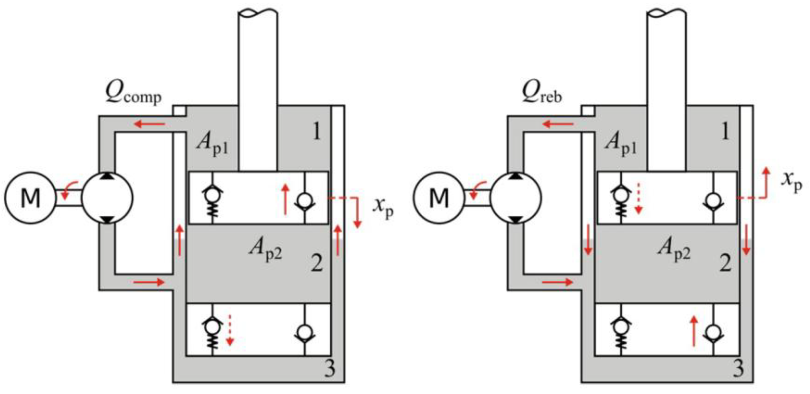
For the indirect drive system with the fluid motion rectifier, Ebrahimi, Bolandhemmat [30] believed that the fluid motion rectifier is heavy, expensive, and consumes too much energy. More disadvantages were addressed by Crolla [73] who pointed out that not only will the fluid leakages and raptures decrease the reliability, but also will they degrade the suspension performance which is limited by the narrow excitation frequency bandwidth of the hydraulic/pneumatic system. Additionally, more energy is dissipated with the increased temperature of the fluid.
Ultimately, considering the difference of the transducers of the different drive modes, it is suggested in future studies to use the same generator constant or electromechanical coupling constant so that the energy generating ability and the motor resistance force can be compared.

5. Hybrid System and Its Technologies

In addition to the direct drive system and indirect drive system, many innovations have been proposed to combine the multiple drive modes together for improving both the reliability and damping performance.
As shown in Figure 19, Singh and Satpute [81,82] proposed a dual cylinder system where the main cylinder works as a shock absorber dampening the vibration through the vehicle suspension and also providing the drive to the secondary cylinder for the velocity amplification. When the secondary cylinder fails, the main cylinder will continue to operate as a passive damper. Considerable amount of energy can be generated without compromising the ride comfort and the road handling performance.
A more complex design was proposed by Xie, Li [51] shown in Figure 20. The secondary piston driven by the main viscous piston has the rack and pinion mechanism. The DC generator is attached at the bottom of the secondary piston to harvest energy. This layout improves the system reliability with the fail-safe mode.
To further reduce the amount of dissipated energy due to the viscosity of the piston liquid, as shown in Figure 21, Demetgul and Guney [83] developed a hydraulic regenerative shock absorber that scavenges energy from both hydraulic fluid motion and shock body motion. Both the power generated from the hydraulic piston generator and the linear generator can be used to charge the energy storing devices.
Although most of the hybrid systems have the failsafe mode, the main drawback of the hybrid systems is the low reliability brought by the complexity of the design that can potentially increase the chance of failure. A large number of components can also dissipate additional amount of energy, resulting in lower power output in comparison with the direct drive system and indirect drive system. In addition, the space constraint of the shock absorber makes the hybrid system less plausible. The hybrid systems are summarized in Table 4 below.

6. Damping and Vehicle Dynamic Performance

Traditional shock absorbers utilize the viscosity of the fluid inside the cylinder to dampen the vehicle suspension vibration, and the damping coefficient of the shock absorber can be changed by tuning the size of the orifice. Whereas in the regenerative shock absorber where the kinetic energy is converted into electrical energy, the damping effect is entirely or partially contributed by the energy harvesting devices such as a generator.

6.1. Damping Performance of the Direct Drive System

The damping coefficient of a passenger vehicle quarter suspension is approximately 1500 Ns/m [84] and 8000–10,000 Ns/m for heavy duty vehicles [85]. According to Yan and Sun [86], equivalent damping coefficient of the electromagnetic generator in the regenerative shock absorber can be expressed by Equation (2) if the damping performance is entirely provided by the electromagnetic generator.
c e q = k i 2 R
where ki is the product of the magnetic field intensity and coil length; R is the total electrical resistance. Therefore, for a regenerative shock absorber with a damping coefficient of 1500 Ns/m on a passenger vehicle suspension and a 10 Ω electrical resistance, the electromagnetic coupling coefficient is calculated by Equation (2) and given by ki = 122.5 Tm which is a large value, meaning that it can only be realized using multiple strong magnet arrays and a coil that has sufficient length. The packaging space of a shock absorber is limited, thus making it difficult to provide enough damping performance with only a direct drive system.
In order to meet the damping requirement of the shock absorber for vehicle dynamics, many innovations have been proposed with an additional damper in parallel with the direct drive energy harvester. Asadi, Ribeiro [45] proposed to have a viscous damper and a direct drive linear motor fused together, shown in Figure 22. This design enables the regenerative shock absorber to have additional damping performance provided by a hydraulic piston. Experimental results showed that a damping coefficient of 1302–1520 Ns/m can be obtained for the regenerative shock absorber.
To further improve the damping performance of the shock absorber, Magnetorheological (MR) fluids are applied to achieve variable damping control. Chen and Liao [24] developed a parallel damper consisting of MR damper and electromagnetic generator, shown in Figure 23. The generated power can then be utilized as the power supply for the MR current driver and sensors. A damping force of 700 N can be achieved under 11mm excitation at 1Hz and simultaneously a maximum of 2 V can be harvested. Damping force control algorithm can also be integrated in the MR energy harvesting damper for optimum vibration control [43,46].

6.2. Damping Performance of the Indirect Drive Systems

For the indirect drive systems, because of the presence of the speed amplifying mechanism, the back electromagnetic force of the generator can be amplified to obtain larger damping. However, one common problem exists in most of the indirect drive systems incorporated with a motion rectifier. During half the time of the conversion from the bidirectional motion of shock body to the unidirectional rotation of the generator, the mechanism becomes disengaged and the generator continues to rotate due to inertia, resulting in the absence of the damping force in half of the motion cycle. The indirect drive systems equipped with one overrunning clutch or one-way bearing tend to present such problem, as shown in [55,57,76,79].
To obtain the stable damping force throughout the entire motion cycle, the designs are upgraded with two clutch systems [47,49,59]. These two clutches are installed facing each other on the drive shaft and both connected with same output shaft. Therefore, when the drive shaft rotates in two directions, one of the clutches will always remain engaged, as shown in Figure 24.
According to Zhang, Zhang [49], the damping force measured experimentally is shown in Figure 25, it can be seen that the damping force applies for both compression and recoil phase of the shock absorber with higher frequencies yielding higher damping force.
In the hydraulic indirect drive systems, the damping force can also apply throughout the whole motion cycle shown in Figure 26, as a result of having flow resistance in both directions. Comparing the direct drive with the indirect drive system, the latter has a larger damping coefficient than the former as long as the damping is presented throughout the entire motion cycle. This damping effect is caused by the friction loss of the speed amplifying mechanism and energy loss of the complex mechanism operation. Therefore, a trade-off between the vibration control and energy harvesting need to be reached through a control algorithm. The damping coefficient and force results of the regenerative shock absorbers are compared and listed in Table 5 below.

7. Circuit and Control Algorithms for Enhancing Power Output and Vehicle Dynamics

The regenerative shock absorber system can generate power for electrical applications. Due to the difference in the power requirement between the power generating element and the power receiving element, the regulation and rectification are essential for the electrical circuits of energy harvesting and storage. In addition, the control parameters may influence the dynamic performance of the vehicle suspension system and energy dissipation performance [87]. Therefore control algorithms need to be incorporated to improve vehicle dynamics and/or the energy harvesting ability by adjusting the parameters according to the input excitation levels [88].

7.1. Power Maximization

Because the direct drive system has AC output and the indirect drive system has DC output, to obtain the steady DC current for charging battery, many direct drive systems incorporated the rectification bridges [2,44,89], as shown in Figure 27.
A drawback of this layout is that a full wave rectified output is a pulsed DC and it is advisable to add a reservoir capacitor for smoothing out the variations. An excessive number of diodes would also consume electrical energy. Arroyo, Badel [90] proposed the Synchronous Magnetic Flux Extraction (SMFE) circuits with only two diodes, shown in Figure 28 Top. The SMFE circuit is suitable for electromagnetic vibrational energy harvesting.
Based on the research conducted by Sanchez, Jodka [91] shown in Figure 28 Bottom, with the same generator resistance, the SMFE method can extract higher amount of energy than that with a voltage doubler circuit or full bridge rectifier. Another advantage brought by using the SMFE other than simply using shunt resistance is that it also incorporates the rectification and amplification of the voltage, thus increasing the efficiency of the electromagnetic energy harvester [92]. For the similar purpose, Dwari and Parsa [93] proposed an alternating current to direct current (AC-DC) step-up converter that can be applied on regenerative shock absorber to charge the battery, as shown in Figure 29. It consists of a boost and buck boost converter connected in parallel and achieves an efficiency of 61% which is better than that by using a conventional bridge rectifier.
For the indirect drive system, due to the motion rectifier, the bidirectional to unidirectional conversion of output voltage is no longer necessary. In many designs [80,83,94], the DC generator is characterized by an internal inductance and a resistance, and is connected to a single external resistance over which the power can be extracted, as shown in Figure 30. However, under the random road excitations, in order to charge the energy storing devices, a regulator needs to be included in the circuit as the generator voltage output needs to be regulated to steadily stay at a certain voltage level. Therefore, many efficient DC-DC converters are proposed in accordance with the targeted output ranges [95,96,97].

7.2. Vehicle Dynamic Control

In addition to energy harvesting, most regenerative shock absorber systems operate inversely as a part of the active suspension system or semi-active suspension system when the external power is applied [98]. Many studies have been done on how to improve vehicle dynamics with the electromagnetic shock absorber [3,6,7,8,9,99,100,101,102].
Fukumori, Hayashi [52,103] conducted the experiments using coupled electromagnetic dampers dampers that can tune the bouncing and rolling modal frequencies of the vehicle independently through a variable external resistor, the schematic of which is shown in Figure 31. However, the voice coil motor was used in the experiment instead of the originally proposed ball-screw regenerative shock absorber system, therefore the energy harvesting performance was not able to be evaluated under the condition where the ride comfort was optimized.
Skyhook control strategy assumes that there is a dashpot of damping Csky on the top of the sprung mass to dampen the vehicle body vibration from the road unevenness excitation [104]. Choi, Seong [77] designed a suspension system based on the electrorheological fluid damper with skyhook controller, the model of which is simulated to compare its simulation results with the experimental results in terms of attenuating vibration. It was found that the skyhook controller powered by the regenerative shock absorber system can significantly reduce the vibration. Ding, Wang [89] implemented Skyhook controller in the active control mode for vibration isolation. Hsieh, Huang [105] proposed the concept where a switched-mode rectifier (SMR) was used to provide positive or negative damping by implementing a skyhook control strategy, as shown in Figure 32. The results showed that the SMR can provide electrical damping based on the skyhook response outcome to achieve the balance between the passive control and the active control. His later research also indicated that the SMR can improve the harvesting efficiency for up to 14% [106].

7.3. Balance between the Energy Harvesting and Vehicle Dynamic Performance

Due to the contradiction between the energy harvesting and ride comfort, compromises have been made for the balance of the ride comfort, road holding and power generation. Ataei, Asadi [107] provide all the possible solutions as Pareto front by prioritizing one of the three objectives. It is shown that the optimized system can deliver better comfort and handling than the non-optimized system. Similar method was adopted by Clemen, Anubi [108] for obtaining the best trade-off between the objectives. For the same purpose of finding the best trade-off between vehicle dynamic performance and energy harvesting, Casavola, Di Iorio [109] proposed the maximum induced power control (MIPC) algorithm that can improve the energy harvesting ability without sacrificing the other objectives.
The concept of mode switching was also introduced to harvest the energy without compromising the ride and comfort performance. Zheng, Yu [53] proposed a system featuring the mode switching operation, namely, the electric motor mode and regenerative braking mode. In the electric motor mode, the optimal ride and comfort performance can be achieved through the active control by tuning the external circuit; in regenerative braking mode, the system can harvest energy while improving the ride and comfort performance. This operation can be achieved through the H bridge switching between the regeneration/actuation mode, one example of the operation is shown in Figure 33 [110]. Nakano [76] and Nakano, Suda [111] proposed another mode switching system featuring regeneration mode, drive mode and brake mode, allowing the system to respond instantly to the stroke velocity, as shown in Figure 34. The possibility of powering the actuator in the motor mode utilizing the power generated in the regenerative mode was also discussed and it was concluded that this self-power operation is somewhat achievable even though the actuation force is slightly insufficient. This combination of vibration control and energy harvesting is called regenerative vibration control, which can be used in regenerative building vibration controls [112,113,114,115,116] and vehicle regenerative shock absorber systems [117,118]. The control algorithms are summarized in Table 6 below.

8. Road Excitation Input

In order to evaluate the regenerative shock absorber, a certain road excitation input needs to be applied so that the output response of the system can be analyzed. Sinusoidal signal, step signal and random signal have been utilized by many researchers to simulate the road displacement excitation input.

8.1. Sinusoidal Displacement Excitation Input

Sinusoidal displacement excitation input has been widely applied to simulate the excitation input because it presents a certain excitation frequency. For a linear regenerative suspension system, its natural resonant frequencies can be targeted to maximize power output and the harvesting efficiency. According to Wang, Liang [121], given the input excitation frequency, the power input and output can be calculated to give system energy harvesting efficiency. With the sinusoidal road displacement excitation input, the voltage output appears to be sinusoidal, which can be rectified into DC voltage.

8.2. Step Input

The use of a step signal as the road displacement excitation input can evaluate the regenerative shock absorber’s vibration response time and attenuation ability, thus giving the idea of how the vehicle responses to a single road bump. In their paper, Li and Zuo [122] compared the vehicle responses to a 10 mm step road displacement excitation for the vehicle suspension fitted with three regenerative shock absorbers in terms of weighted acceleration, dynamic/static tire force ratio, suspension deflection, harvested power and damping force.

8.3. Road Displacement Profile

In addition to the sinusoidal and step input, the road class model has also been applied to the regenerative shock absorber based on its roughness classification since the road roughness has a significant impact on the power dissipated in the shock absorber [123]. Goldner, Zerigian [42] included the road profile in the experiment by using a rotating wheel with a bump. However, this setup cannot fully resemble the real road condition which has a more random displacement profile. In order to evaluate the performance of the regenerative shock absorber on different road conditions, the road model and its classification were introduced to conduct the simulation accurately. According to ISO-8608, A to H are used to classify the roads [124]. Many authors have incorporated road models with the classifications in the simulation as the input excitation [50,120,125,126].
The power spectral density (PSD) functions of the road displacement input are given by:
{ G d ( n ) = G d ( n 0 ) ( n n 0 ) 2 G d ( Ω ) = G d ( Ω 0 ) ( Ω Ω 0 ) 2
where G d ( n ) and G d ( Ω ) are the PSD functions of the vertical displacements which are functions of spatial frequency n and of angular spatial frequency Ω. G d ( n 0 ) and G d ( Ω 0 ) are given in Table 7 below corresponding to the road classifications.
Kawamoto, Suda [54] developed the PSD of the road elevation profile shown in Figure 35. The road profile equivalent to level C was generated with random roughness and used in the simulation as an input source. The PSD functions of the bounce and pitch road displacement input profiles were developed by Nakano [76], taking into consideration of the time delay between the wheels due to the vehicle travelling, as shown below:
{ P 0 b ( f t ) = v R f t 2 cos 2 ( f t v π ( l f + l r ) ) P 0 p ( f t ) = 4 v R ( l f + l r ) 2 f t 2 sin 2 ( f t v π ( l f + l r ) )
Xie, Li [51] compared the output power of the regenerative shock absorber under the different road classes, shown in the Figure 36. The result showed that the more pronounced the road roughness is, the more the power output at certain vehicle velocities.

8.4. Road Test

Road test is the most straightforward and simplest way to demonstrate the performance of the shock absorber in the real world. The accelerometers were mounted on the sprung mass and unsprung to pick up the acceleration signals and data acquisition device was placed in the vehicle cabin to record the test data. A double clutch ball screw based regenerative shock absorber designed by Liu, Xu [59] was tested on a Ford F250 in place of the traditional oil damper, as shown in Figure 37. The vehicle was driven at 64 km/h on the paved road, it is shown that with a 10 Ω external resistance, the total power output was in phase with the voltage output and an average of 13.3 W could be harvested over 8 s. As shown in Figure 38, a similar test was conducted by Li, Zuo [127] to assess the feasibility of the proposed regenerative shock absorber, an average of 15.4 W could be harvested over 8 s with a 20 Ω external resistance, when the vehicle was driven at 24 km/h on a circled campus road. It is also indicated that the power output was out of phase with the road displacement, which means that in addition to the excitation displacement amplitude, the excitation displacement phase could also affect the power output.
In order to evaluate the results in the frequency domain, Liu, Li [98] proposed to have the regenerative shock absorber installed on a self-made electric vehicle driven at 20 km/h on a Class B road, as shown in Figure 39. In the road test, the comfort levels of the passive damper and the proposed regenerative damper with the Variable Universe Fuzzy (VUF) control were compared and the results are shown in the frequency domain. It can be seen that the VUF control lowered the vehicle body acceleration and such reduction was more obvious at the resonant frequencies.

9. Nonlinearity

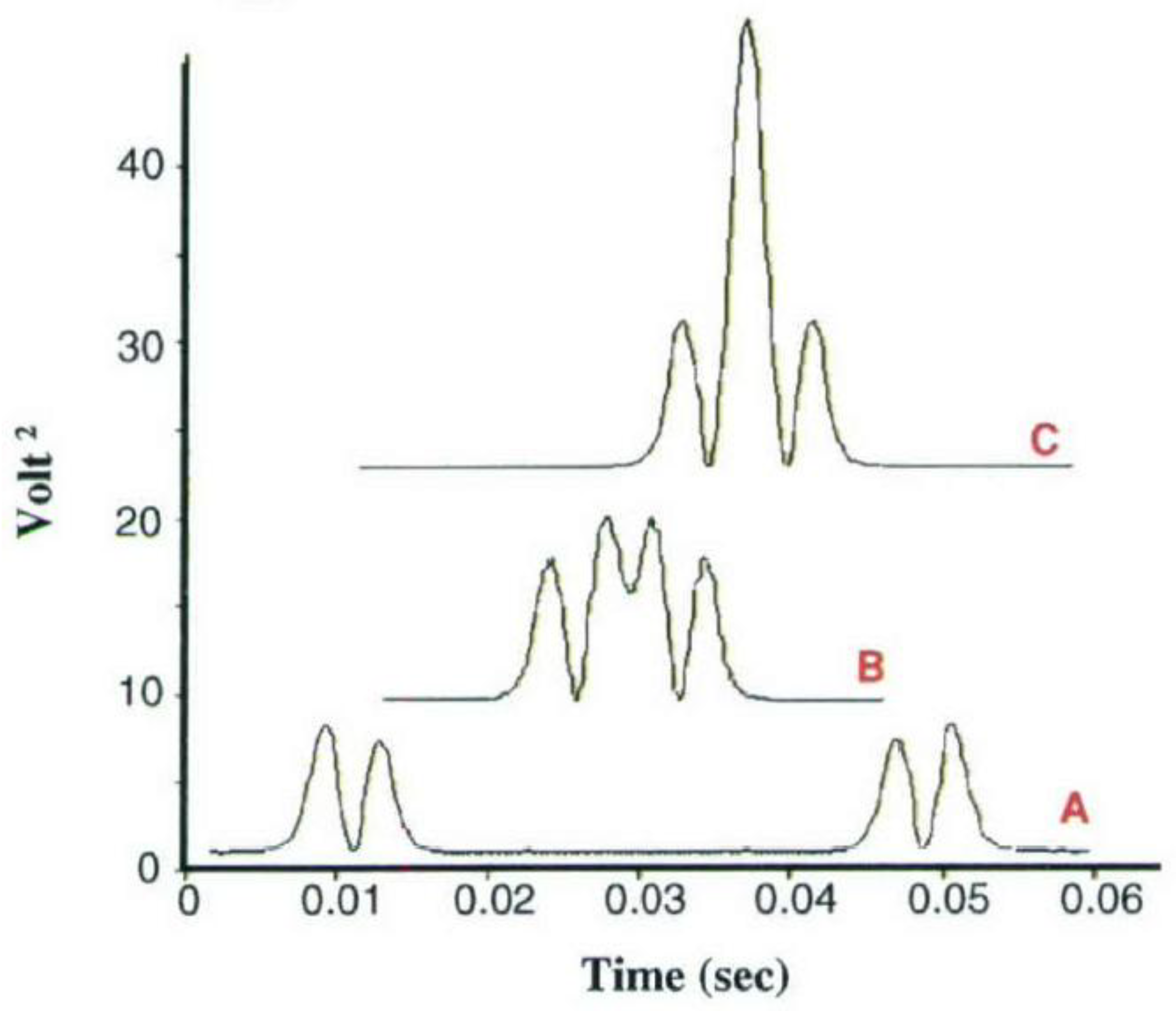
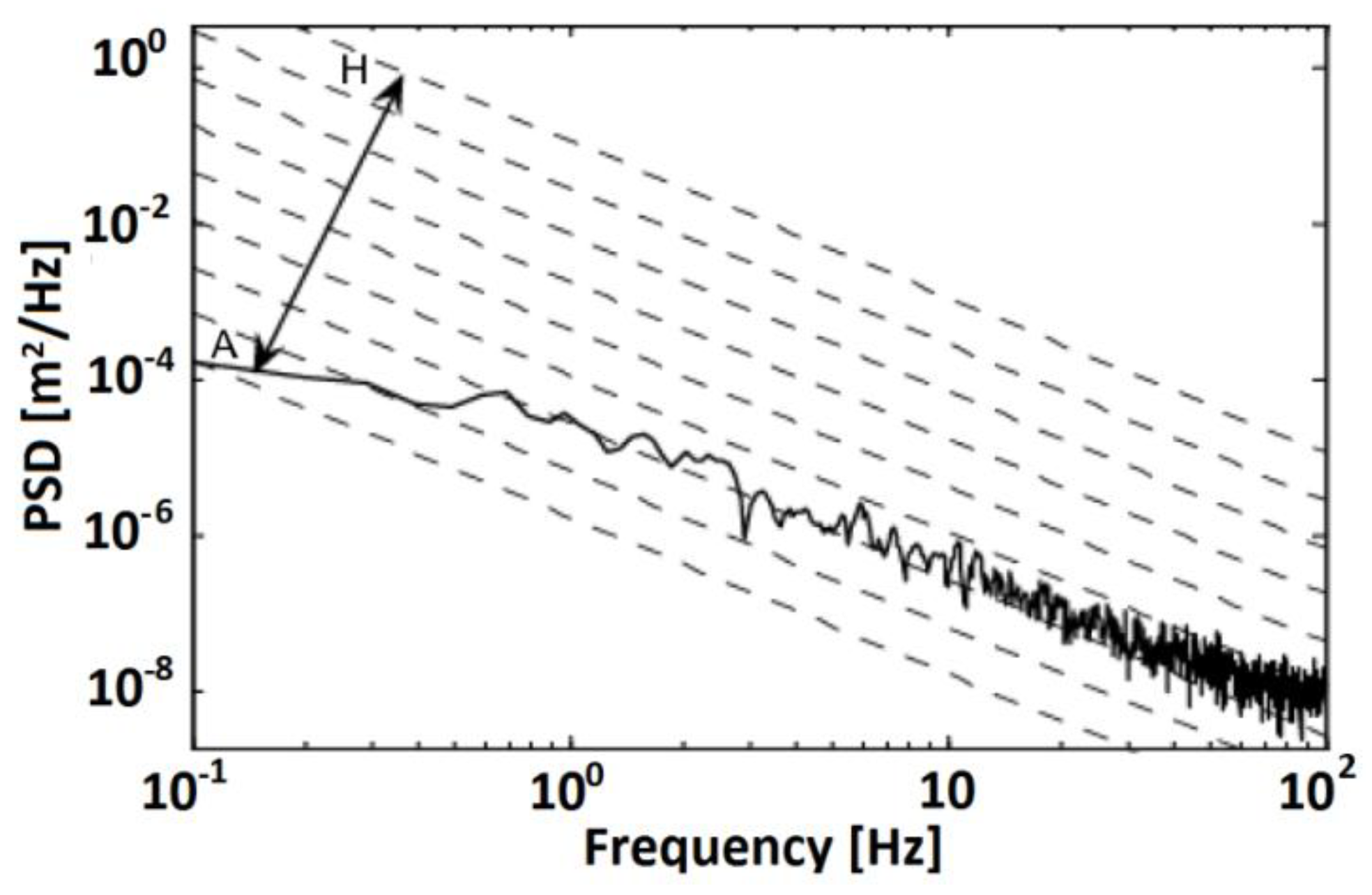
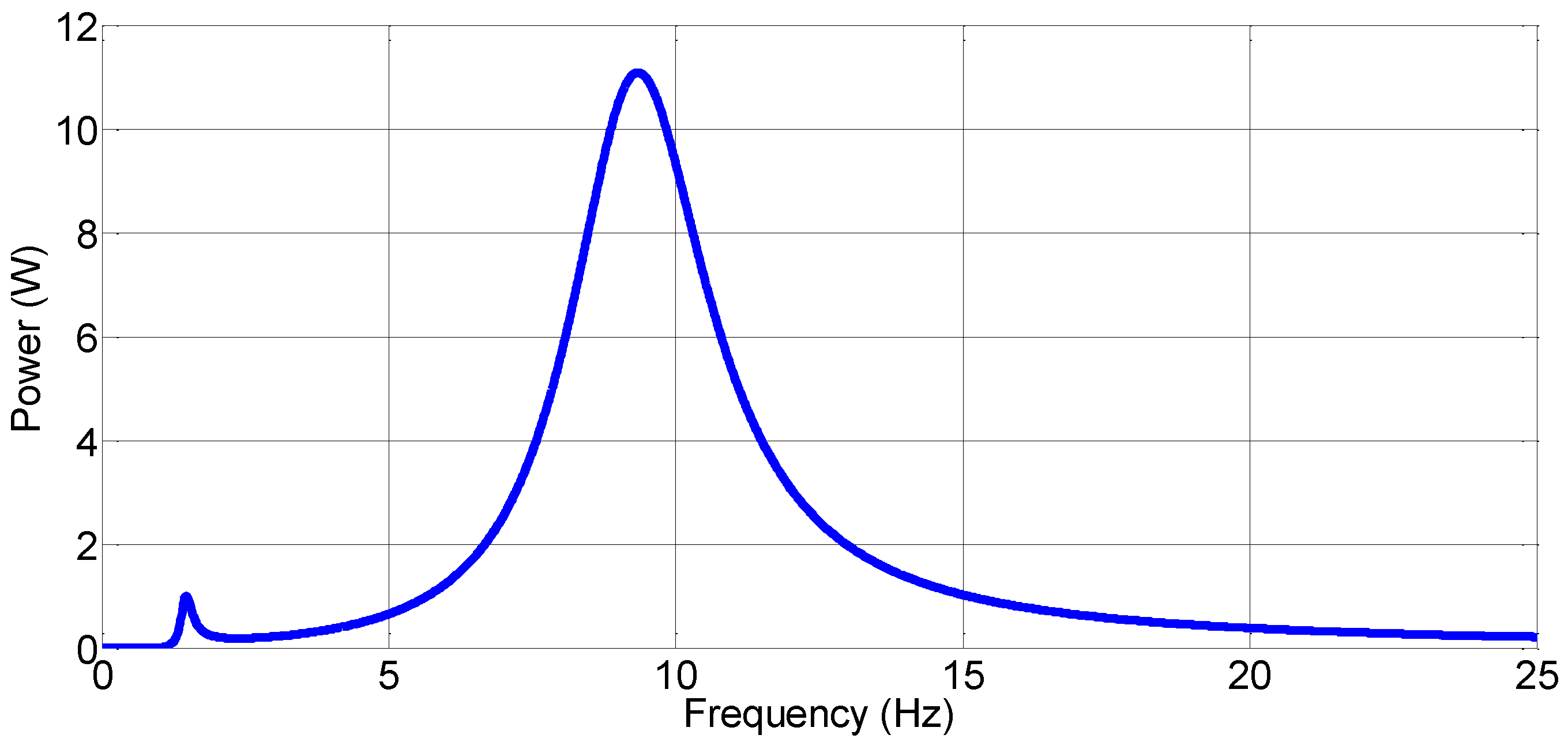
Due to the nature of the linear regenerative vehicle suspension, more energy can be harvested at the resonant natural frequencies. Figure 40 is an example of the frequency spectrum of the power generation in a quarter vehicle regenerative suspension system [128]. One of the drawbacks of the linear regenerative vehicle suspension is that the resonant peak frequency bandwidth is really narrow, resulting in very little energy that can be regenerated [129]. The use of nonlinear spring can broaden the energy harvesting bandwidth or shift the modal resonant frequency to achieve higher power, which is especially suited for energy harvesting from random vibration [130]. For these purposes, many researchers have studied nonlinear system model that can be adopted for the regenerative vehicle suspension system [131,132,133,134,135].
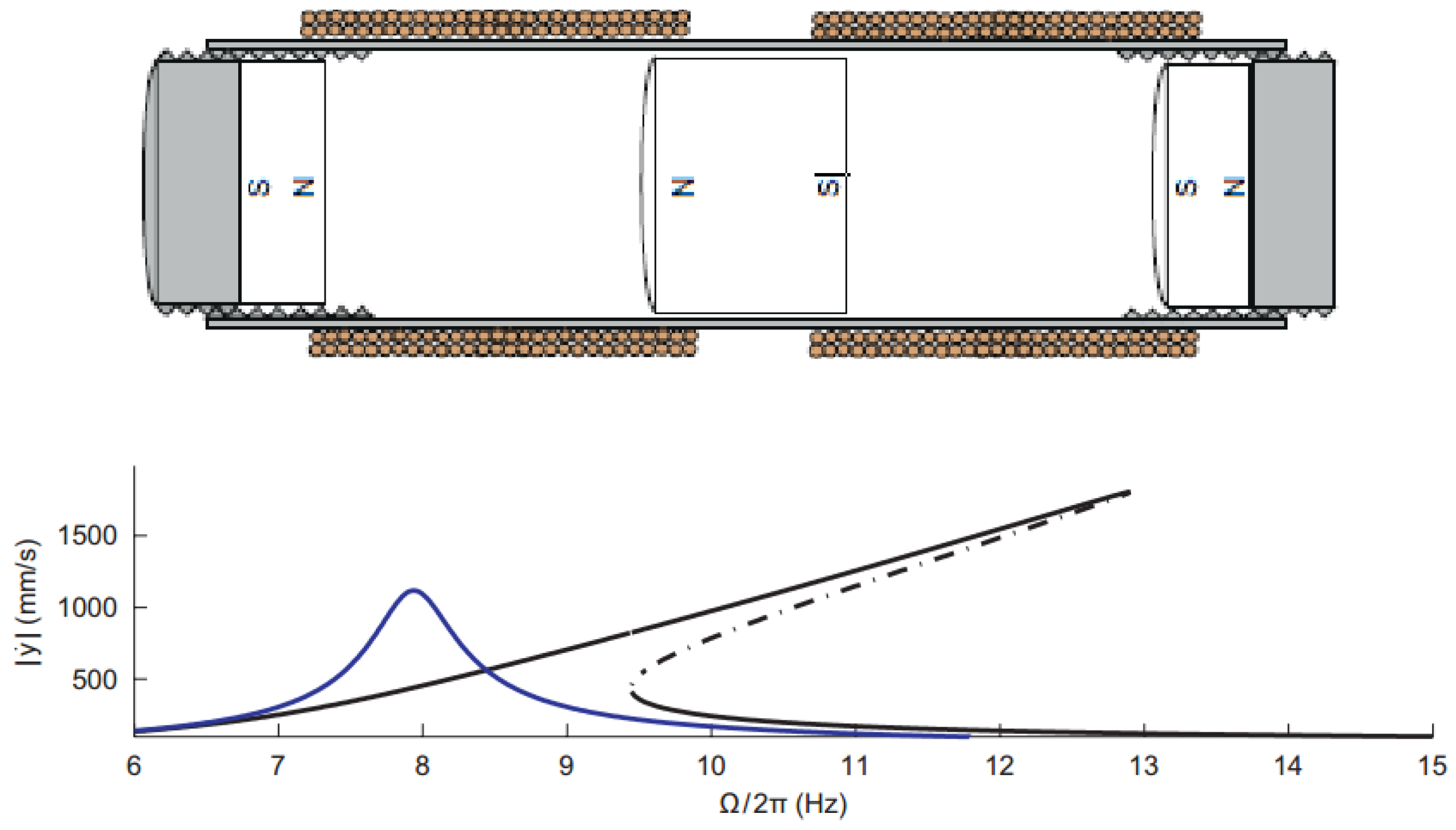
A magnetic levitation energy harvesting device was proposed by Mann and Sims [136] and shown in 
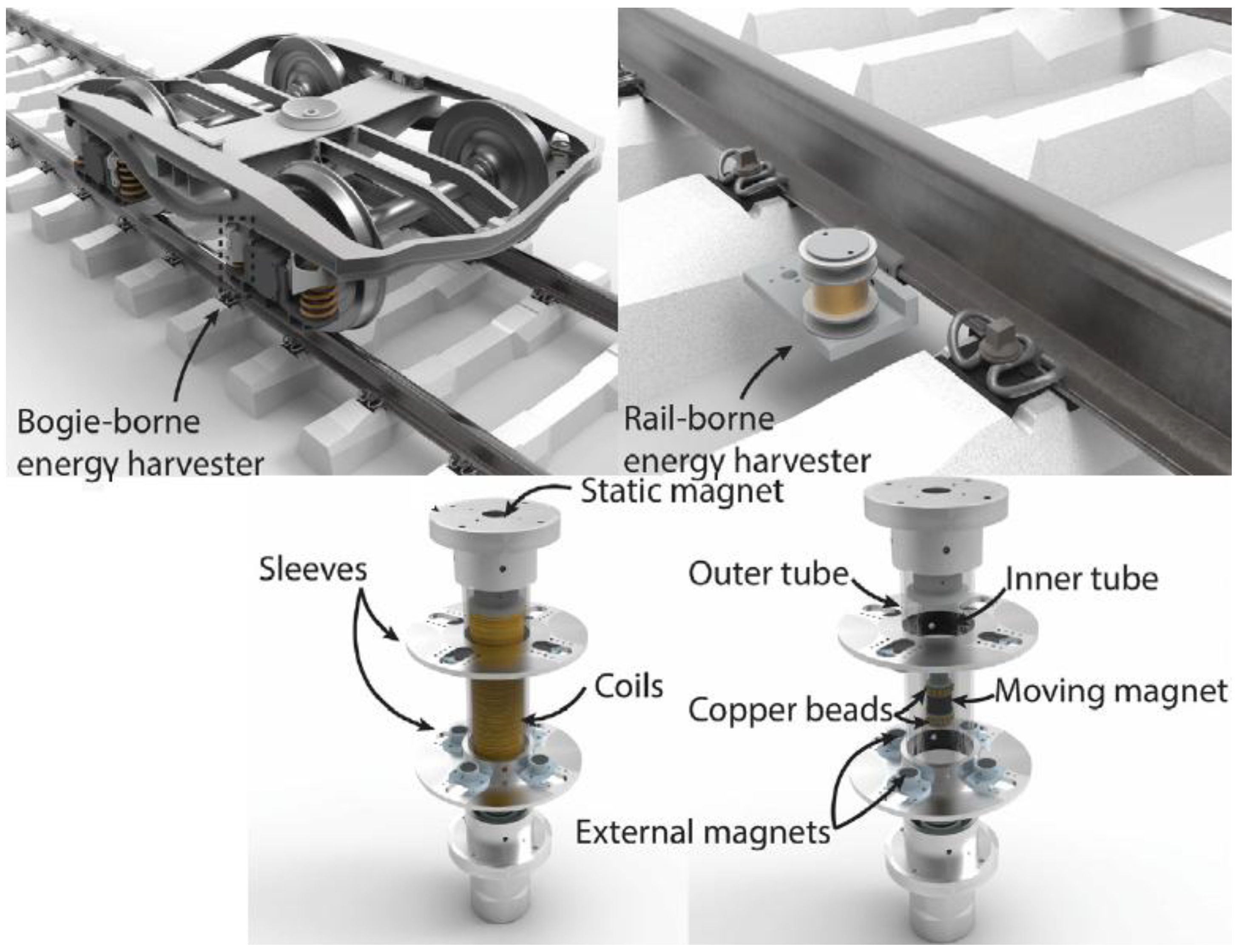
Figure 41. The mathematical model could be obtained using the Duffing equation and it was found that the nonlinearity was applicable to larger excitation displacement amplitude, resulting in a broader harvesting frequency bandwidth. The peak power could be obtained away from the equivalent resonant frequencies. Gao, Wang [137] proposed the similar magnetic levitation system for harvesting energy from rail and bogie as shown in Figure 42. Another interesting innovation was brought by Barton, Burrow [129] who further increased the bandwidth by changing the load resistance. It was also discovered that the nonlinearity presents super-harmonic resonances well above the natural frequencies of the equivalent linear system, allowing the system to respond at a frequency higher than the excitation frequency. This up-frequency conversion could be useful for the low frequency operation such as a vehicle suspension system.
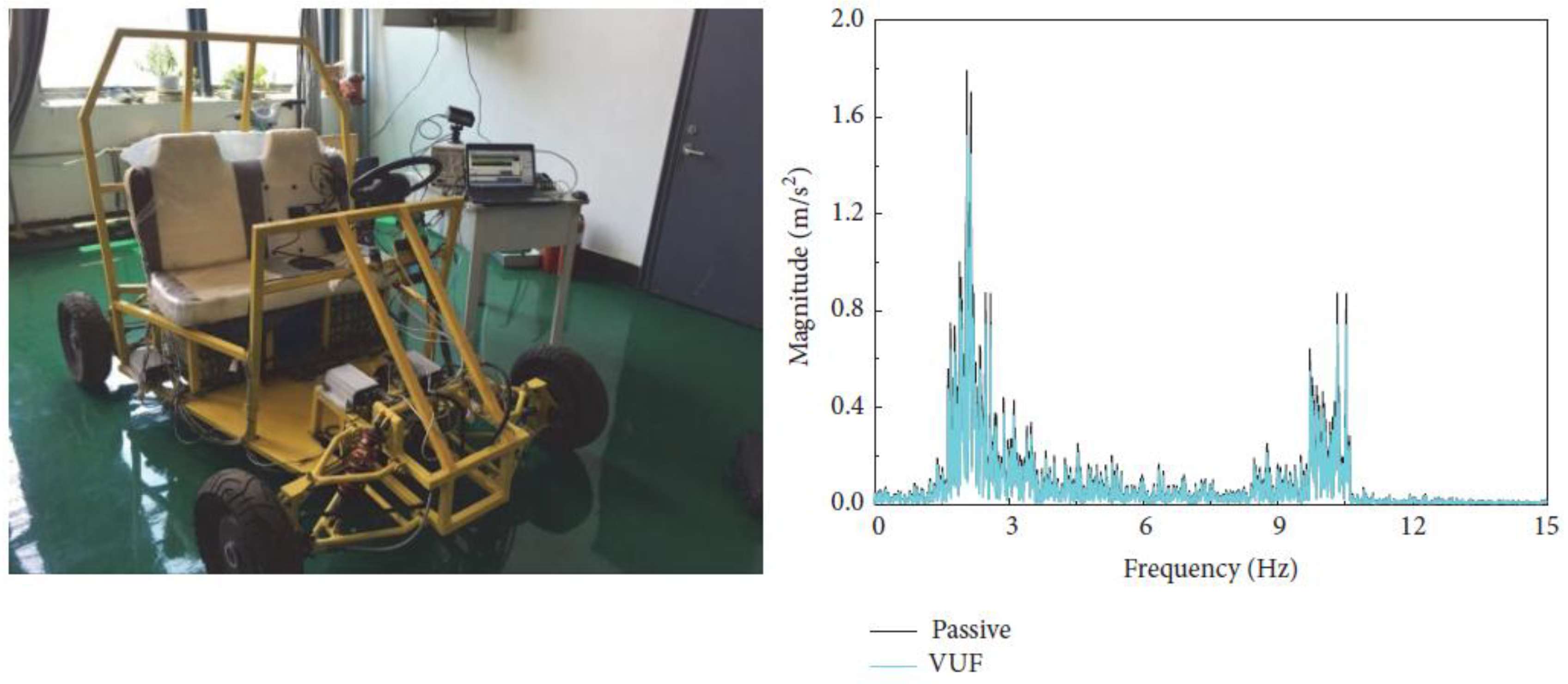
There have been a number of suspension system designs that incorporate the nonlinearity model due to its advantages in prediction of vehicle dynamics. Özcan, Sönmez [
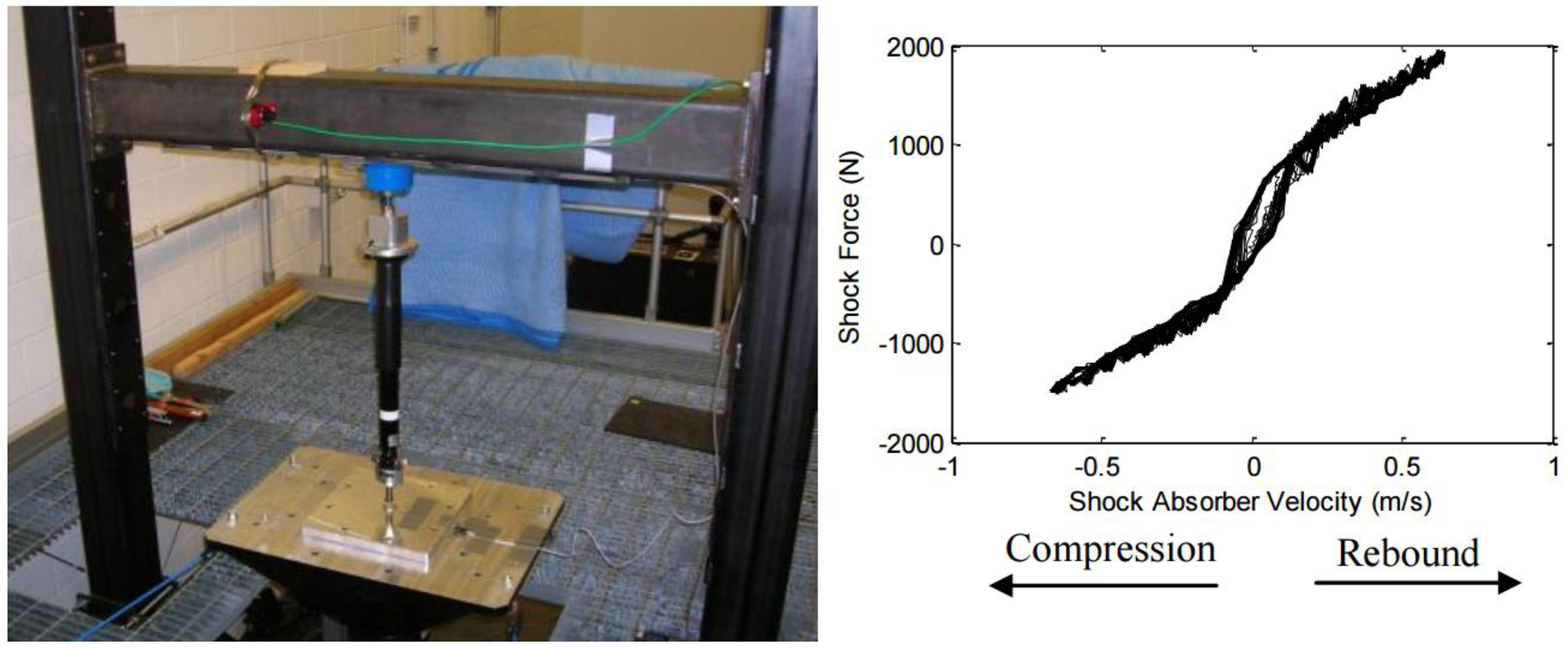
138] evaluated the nonlinear spring and nonlinear damper in the half car system to optimize the comfort and the handling of the light vehicle. Similar dynamic study was conducted by Cui, Kurfess [139] on the shock absorber in a Mazda CX-7, the test result clearly showed that the nonlinearity was involved in the operation shown in Figure 43. The stability and comfort of the vehicle could be improved by this nonlinearity.
Although the concept of the nonlinearity model has been largely applied on the vehicles to predict vehicle vibration response due to the road profile excitation, there have not been many investigations undertaken for the nonlinear model of the vehicle suspension system built with the regenerative shock absorber in terms of harvesting energy, which can be identified as a research gap and should draw more attention considering the potentials of the regenerative shock absorber and its readiness to be implemented. The potential advantages of the nonlinear regenerative shock absorbers are:
  • Widening the frequency bandwidth for harvesting more energy on the random road surface.
  • Shifting the harvesting frequency away from the vehicle equivalent resonant frequency for better reliability.
  • Converting the low road excitation frequency into high energy harvesting frequency.
  • Better ride comfort and road handling.

10. Future Direction for Regenerative Shock Absorbers

The rapid developments of the new technologies have improved the feasibility of the regenerative shock absorber. In order to be implemented onto the vehicle, a regenerative shock absorber needs to meet the requirements for the power output, energy harvesting efficiency and vehicle dynamic control. The current regenerative shock absorbers pose some disadvantages, which many authors have attempted to address both mechanically and electrically. Each step forward in the research area would bring them closer to the implementation reality and their sustainability.
The current limitation of the direct-drive regenerative shock absorbers is the constraint of the packaging space. Because the coil speed with respect to the magnets cannot be amplified, the magnets and coils have to be large enough to obtain large electromechanical coupling constant. The main limitation of the indirect-drive regenerative shock absorber is that the complexity of the motion conversion mechanism can affect the vehicle dynamics, resulting in poor handling or discomfort. Therefore, it is suggested that the future design of the regenerative shock absorber should incorporate more efficient magnets, and the coil setup is preferably outside the magnets, and the damping should be presented in both compression phase and the recoil phase of the shock absorber motion. It is also expected that the mechanism needs to be less complicated to reduce the friction energy loss. For the regenerative shock absorber containing hydraulic/pneumatic system, the response time needs to be reduced to obtain the instant control of the vehicle.
Many researches have been done focusing on improving the performance of the regenerative shock absorbers, however, the integration with the vehicle has not been addressed enough yet. In the future research, it is recommended that dynamic model of the full vehicle needs to be considered as the platform for the regenerative shock absorbers, since the evaluation based on the full vehicle suspension system is more accurate and closer to the reality. Based on the full vehicle suspension system model, a nonlinear suspension can also be studied for its advantages in broadening the energy harvesting bandwidth.
Active control is another area to be researched. Due to the contradiction between the energy harvesting and vehicle dynamic control performances, a control algorithm is needed to make a compromise between both the performances in accordance with the condition of the road surface and driver’s demand. A power generating element can be used reversely as an actuation element when the active control becomes the priority and vice versa. Ideally, a balance point can be identified by the control system. As a result, the self-powering can be achieved intellectually where the energy harvested at the regeneration mode of the transducer is enough to power the actuation mode. Hence, future research should concentrate more on the active control algorithm and its incorporation with the energy harvesting.

11. Our Contributions

Our group has started the research work of the electromagnetic vibration energy harvesters since 2014 [140]. The time domain and frequency analysis approaches have been applied to solve the system equations[121,140,141]. The performance of electromagnetic vibration energy harvesters have been analyzed and optimized in dimensionless forms and compared with that of the piezoelectric vibration energy harvesters for different interface circuits [140,142,143,144]. Coupling loss factor of linear vibration energy harvesting systems in a framework of statistical energy analysis has been defined [140,144,145], the frequency ranges to enable statistical energy analysis of the electromagnetic vibration energy harvesters have been identified [140,145]. The relationships of coupling loss factor, dimensionless force factor, critical coupling strength, coupling quotient, electro-mechanical coupling factor, damping loss factor and modal densities have been established. The relationship of vibration energy harvester performance with dimensionless force factor has been disclosed. Numerical ranges of the dimensionless force factor have been defined for cases of weak, moderate and strong coupling [140,144]. The 2DOF vehicle quarter suspensions with piezoelectric and electromagnetic vibration energy harvesters have been studied where a dimensionless analysis method was proposed to predict the output voltage and harvested power for a 2DOF vibration energy harvesting system. This method allows us to compare the harvesting power and efficiency of the 2DOF vibration energy harvesting system and to evaluate the harvesting system performance regardless of the sizes or scales [11,141]. The quarter vehicle suspension system with linear regenerative electromagnetic shock absorber was simulated using Matlab® and Simulink®. The prototyped regenerative shock absorbers have been built and tested. The simulation model was established and validated via experiments. The validated simulation model was then used for the analysis of the system parameter sensitivity. The sensitivity analysis then led to the design optimization which allowed to maximize the vibrational energy harvesting [141].

12. Conclusions

The potential in converting vibration energy into electrical energy through the shock absorber is promising and rewarding and can make the vehicle more sustainable by consuming less amount of fuel.
In this paper, the recent technologies involved in regenerative shock absorber systems have been reviewed and categorized mainly into three types based on the conversion mechanisms: direct drive, indirect drive and hybrid. Their comparisons have been presented to understand the advantages and disadvantages in terms of conversion efficiency and compatibility. Damping performance of the regenerative shock absorber has been evaluated based on the drive modes as it is the original and basic function of the shock absorber.
In addition to the mechanical mechanism, electrical circuit and control algorithm are also the key components of the regenerative shock absorber system and can largely affect the overall performance. With the proper control system, a balance state can be reached between the energy harvesting and vehicle dynamic control to obtain a better overall performance. A comprehensive review has also been conducted on each type of the road profile excitation inputs. This paper also presents the current technologies of the nonlinear models that are applicable onto the shock absorber system. It can thus be suggested that the efficiency evaluation of the drive modes and the nonlinear analysis of the regenerative shock absorber should be the focus of the research in the near to medium future. Finally, the recent works of our group have also been outlined to demonstrate the original contributions in this field.

Author Contributions

Resources and writing: Ran Zhang; Supervision: Xu Wang; Review & Editing: Xu Wang & Sabu John.

Acknowledgments

Authors would like to thank Australian Research Council Linkage Project grant LP160100132 for funding support.

Conflicts of Interest

The authors declare no conflict of interest.

Nomenclature

Bmagnetic field intensity
Ltotal coil length of the electromagnetic generator
Blthe product of B and l or electromechanical coupling
Uvoltage harvested over the external resistance
Vcoil speed with respect to the magnets
Ceqequivalent damping coefficient
Kimotor constant or electromechanical coupling
Rexternal resistance
Nspecial frequency
Ωangular spatial frequency
G d ( n ) the vertical displacement with respect to the spatial frequency n
G d ( Ω ) the vertical displacement with respect to the angular spatial frequency Ω
G d ( n 0 ) the vertical displacement when n0 = 0.1 cycle/m
G d ( Ω 0 ) the vertical displacement when Ω0 = 1 rad/m
PobPower spectral density of bounce
PopPower spectral density of pitch
fsspatial frequency
lfdistance between centre of gravity of the vehicle and the front bumper
lrdistance between centre of gravity of the vehicle and the rear bumper

References

  1. Lafarge, B.; Cagin, S.; Curea, O.; Perret, A.H. From functional analysis to energy harvesting system design: Application to car suspension. Int. J. Interact. Des. Manuf. 2016, 10, 37–50. [Google Scholar] [CrossRef]
  2. Zuo, L.; Scully, B.; Shestani, J.; Zhou, Y. Design and characterization of an electromagnetic energy harvester for vehicle suspensions. Smart Mater. Struct. 2010, 19, 045003. [Google Scholar] [CrossRef]
  3. Fayyad, S.M. Constructing control system for active suspension system. Contemp. Eng. Sci. 2012, 5, 189–200. [Google Scholar]
  4. Gao, H.; Lam, J.; Wang, C. Multi-objective control of vehicle active suspension systems via load-dependent controllers. J. Sound Vib. 2006, 290, 654–675. [Google Scholar] [CrossRef]
  5. Popovic, V.; Jankovic, D.; Vasic, B. Design and Simulation of Active Suspension System by Using Matlab. In Proceedings of the FISITA World Automotive Congress, Seoul, Korea, 12–15 June 2000. [Google Scholar]
  6. Rao, K.D. Modeling, simulation and control of semi active suspension system for automobiles under matlab simulink using pid controller. IFAC Proc. Vol. 2014, 47, 827–831. [Google Scholar] [CrossRef]
  7. Mouleeswaran, S. Design and Development of Pid Controller-Based Active Suspension System for Automobiles; INTECH Open Access Publisher: London, UK, 2012. [Google Scholar]
  8. Ahmed, A.E.-N.S.; Ali, A.S.; Ghazaly, N.M.; El-Jaber, G.A. Pid controller of active suspension system for a quarter car model. Int. J. Adv. Eng. Technol. 2015, 8, 899. [Google Scholar]
  9. Gaur, S. Vibration control of bus suspension system using pi and pid controller. Int. J. Adv. Eng. Sci. 2013, 3, 94–99. [Google Scholar]
  10. Elliott, S.J.; Zilletti, M. Scaling of electromagnetic transducers for shunt damping and energy harvesting. J. Sound Vib. 2014, 333, 2185–2195. [Google Scholar] [CrossRef]
  11. Xiao, H.; Wang, X.; John, S. A dimensionless analysis of a 2DOF piezoelectric vibration energy harvester. Mech. Syst. Signal Process. 2015, 58, 355–375. [Google Scholar] [CrossRef]
  12. Lee, H.; Jang, H.; Park, J.; Jeong, S.; Park, T.; Choi, S. Design of a piezoelectric energy-harvesting shock absorber system for a vehicle. Integr. Ferroelectr. 2013, 141, 32–44. [Google Scholar] [CrossRef]
  13. Xie, X.; Wang, Q. Energy harvesting from a vehicle suspension system. Energy 2015, 86, 385–392. [Google Scholar] [CrossRef]
  14. Priya, S. Advances in energy harvesting using low profile piezoelectric transducers. J. Electroceramics 2007, 19, 167–184. [Google Scholar] [CrossRef]
  15. Lien, I.; Shu, Y. Array of piezoelectric energy harvesting by the equivalent impedance approach. Smart Mater. Struct. 2012, 21, 082001. [Google Scholar] [CrossRef]
  16. Xu, Z.; Shan, X.; Chen, D.; Xie, T. A novel tunable multi-frequency hybrid vibration energy harvester using piezoelectric and electromagnetic conversion mechanisms. Appl. Sci. 2016, 6, 10. [Google Scholar] [CrossRef]
  17. Poulin, G.; Sarraute, E.; Costa, F. Generation of electrical energy for portable devices: Comparative study of an electromagnetic and a piezoelectric system. Sens. Actuators A Phys. 2004, 116, 461–471. [Google Scholar] [CrossRef]
  18. Mitcheson, P.; Reilly, E.; Toh, T.; Wright, P.; Yeatman, E. Transduction mechanisms and power density for mems inertial energy scavengers. Power MEMS 2006, 6, 275–278. [Google Scholar]
  19. Choi, J.-S.; Yoo, J. Design of a halbach magnet array based on optimization techniques. IEEE Trans. Magn. 2008, 44, 2361–2366. [Google Scholar] [CrossRef]
  20. Jang, S.-M.; Jeong, S.-S.; Ryu, D.-W.; Choi, S.-K. Comparison of three types of pm brushless machines for an electro-mechanical battery. IEEE Trans. Magn. 2000, 36, 3540–3543. [Google Scholar] [CrossRef]
  21. Cheng, S.; Arnold, D.P. A study of a multi-pole magnetic generator for low-frequency vibrational energy harvesting. J. Micromech. Microeng. 2009, 20, 025015. [Google Scholar] [CrossRef]
  22. Kulkarni, S.; Koukharenko, E.; Torah, R.; Tudor, J.; Beeby, S.; O’Donnell, T.; Roy, S. Design, fabrication and test of integrated micro-scale vibration-based electromagnetic generator. Sens. Actuators A Phys. 2008, 145, 336–342. [Google Scholar] [CrossRef]
  23. Harne, R.L. Theoretical investigations of energy harvesting efficiency from structural vibrations using piezoelectric and electromagnetic oscillators. J. Acoust. Soc. Am. 2012, 132, 162–172. [Google Scholar] [CrossRef] [PubMed]
  24. Chen, C.; Liao, W.-H. A self-sensing magnetorheological damper with power generation. Smart Mater. Struct. 2012, 21, 025014. [Google Scholar] [CrossRef]
  25. Ebrahimi, B.; Khamesee, M.B.; Golnaraghi, M.F. Design and modeling of a magnetic shock absorber based on eddy current damping effect. J. Sound Vib. 2008, 315, 875–889. [Google Scholar] [CrossRef]
  26. Aldraihem, O.; Baz, A. Energy harvester with a dynamic magnifier. J. Intell. Mater. Syst. Struct. 2011, 22, 521–530. [Google Scholar] [CrossRef]
  27. Lin, X.; Xuexun, G. Hydraulic transmission electromagnetic energy-regenerative active suspension and its working principle. In Proceedings of the 2010 2nd International Workshop on Intelligent Systems and Applications, Wuhan, China, 22–23 May 2010. [Google Scholar]
  28. Noritsugu, T. Energy saving of a pneumatic system (2). Energy regenerative control of a pneumatic drive system. Application to active air suspension. Hydraul. Pneum. 1999, 38, 1–4. [Google Scholar]
  29. Gupta, A.; Jendrzejczyk, J.; Mulcahy, T.; Hull, J. Design of electromagnetic shock absorbers. Int. J. Mech. Mater. Des. 2006, 3, 285–291. [Google Scholar] [CrossRef]
  30. Ebrahimi, B.; Bolandhemmat, H.; Khamesee, M.B.; Golnaraghi, F. A hybrid electromagnetic shock absorber for active vehicle suspension systems. Veh. Syst. Dyn. 2011, 49, 311–332. [Google Scholar] [CrossRef]
  31. Tang, X.; Lin, T.; Zuo, L. Design and optimization of a tubular linear electromagnetic vibration energy harvester. IEEE/ASME Trans. Mechatron. 2014, 19, 615–622. [Google Scholar] [CrossRef]
  32. Cheung, J.T. Frictionless Linear Electrical Generator for Harvesting Motion Energy; DTIC Document: Fort Belvoir, VA, USA, 2004. [Google Scholar]
  33. Zhang, P.S. Design of Electromagnetic Shock Absorbers for Energy Harvesting from Vehicle Suspensions. Master’s Thesis, Stony Brook University, Stony Brook, NY, USA, 2010. [Google Scholar]
  34. Jang, S.-M.; Choi, J.-Y.; Lee, S.-H.; Cho, H.-W.; Jang, W.-B. Analysis and experimental verification of moving-magnet linear actuator with cylindrical halbach array. IEEE Trans. Magn. 2004, 40, 2068–2070. [Google Scholar] [CrossRef]
  35. Zhu, D.; Beeby, S.; Tudor, J.; Harris, N. Vibration energy harvesting using the halbach array. Smart Mater. Struct. 2012, 21, 075020. [Google Scholar] [CrossRef]
  36. Long, Z.; He, G.; Xue, S. Study of eds & ems hybrid suspension system with permanent-magnet halbach array. IEEE Trans. Magn. 2011, 47, 4717–4724. [Google Scholar]
  37. Yan, L.; Zhang, L.; Wang, T.; Jiao, Z.; Chen, C.-Y.; Chen, I. Magnetic field of tubular linear machines with dual halbach array. Prog. Electromagn. Res. 2013, 136, 283–299. [Google Scholar] [CrossRef]
  38. Salauddin, M.; Park, J.Y. Design and experiment of human hand motion driven electromagnetic energy harvester using dual halbach magnet array. Smart Mater. Struct. 2017, 26, 035011. [Google Scholar] [CrossRef]
  39. Zhu, D.; Beeby, S.; Tudor, M.; Harris, N. Electromagnetic vibration energy harvesting using an improved halbach array. In Proceedings of the PowerMEMS 2012, Atlanta, GA, USA, 2–5 December 2012. [Google Scholar]
  40. Zhu, D.; Beeby, S.; Tudor, J.; Harris, N. Increasing output power of electromagnetic vibration energy harvesters using improved halbach arrays. Sens. Actuators A Phys. 2013, 203, 11–19. [Google Scholar] [CrossRef]
  41. Elvin, N.G.; Elvin, A.A. An experimentally validated electromagnetic energy harvester. J. Sound Vib. 2011, 330, 2314–2324. [Google Scholar] [CrossRef]
  42. Goldner, R.; Zerigian, P.; Hull, J. A Preliminary Study of Energy Recovery in Vehicles by Using Regenerative Magnetic Shock Absorbers; SAE Technical Paper 0148-7191; SAE: Warrendale, PA, USA, 2001. [Google Scholar]
  43. Sapiński, B.; Rosół, M.; Węgrzynowski, M. Evaluation of an energy harvesting mr damper-based vibration reduction systemstem. J. Theor. Appl. Mech. 2016, 54, 333–344. [Google Scholar] [CrossRef]
  44. Wang, R.; Ding, R.; Chen, L. Application of hybrid electromagnetic suspension in vibration energy regeneration and active control. J. Vib. Control 2016, 24, 223–233. [Google Scholar] [CrossRef]
  45. Asadi, E.; Ribeiro, R.; Khamesee, M.B.; Khajepour, A. Analysis, prototyping and experimental characterization of an adaptive hybrid-electromagnetic damper for automotive suspension systems. IEEE Trans. Veh. Technol. 2016, 66, 3703–3713. [Google Scholar] [CrossRef]
  46. Sapiński, B.; Rosół, M.; Węgrzynowski, M. Investigation of an energy harvesting mr damper in a vibration control system. Smart Mater. Struct. 2016, 25, 125017. [Google Scholar] [CrossRef]
  47. Li, Z.; Zuo, L.; Kuang, J.; Luhrs, G. A motion rectifier based energy harvesting shock absorbers. In Proceedings of the 2012 ASME Design Engineering Conference, Chicago, IL, USA, 12–15 August 2012. [Google Scholar]
  48. Li, P.; Zuo, L. Assessment of vehicle performances with energy-harvesting shock absorbers. SAE Int. J. Passeng. Cars-Mech. Syst. 2013, 6, 18–27. [Google Scholar] [CrossRef]
  49. Zhang, Z.; Zhang, X.; Chen, W.; Rasim, Y.; Salman, W.; Pan, H.; Yuan, Y.; Wang, C. A high-efficiency energy regenerative shock absorber using supercapacitors for renewable energy applications in range extended electric vehicle. Appl. Energy 2016, 178, 177–188. [Google Scholar] [CrossRef]
  50. Guo, S.; Liu, Y.; Xu, L.; Guo, X.; Zuo, L. Performance evaluation and parameter sensitivity of energy-harvesting shock absorbers on different vehicles. Veh. Syst. Dyn. 2016, 54, 918–942. [Google Scholar] [CrossRef]
  51. Xie, L.; Li, J.; Cai, M. Design of a hybrid energy-harvesting shock absorber. In Proceedings of the International Forum on Energy, Environment Science and Materials (IFEESM 2015), Shenzhen, China, 25–26 September 2015. [Google Scholar]
  52. Fukumori, Y.; Hayashi, R.; Matsumi, R.; Suda, Y.; Nakano, K. Study on Independent Tuning Damping Characteristic by Coupling of Electromagnetic Dampers for Automobiles; SAE Technical Paper 0148-7191; SAE: Warrendale, PA, USA, 2015. [Google Scholar]
  53. Zheng, X.-c.; Yu, F.; Zhang, Y.-C. A novel energy-regenerative active suspension for vehicles. J. Shanghai Jiaotong Univ. Sci. 2008, 13, 184–188. [Google Scholar] [CrossRef]
  54. Kawamoto, Y.; Suda, Y.; Inoue, H.; Kondo, T. Modeling of electromagnetic damper for automobile suspension. J. Syst. Des. Dyn. 2007, 1, 524–535. [Google Scholar] [CrossRef]
  55. Kawamoto, Y.; Suda, Y.; Inoue, H.; Kondo, T. Electro-mechanical suspension system considering energy consumption and vehicle manoeuvre. Veh. Syst. Dyn. 2008, 46, 1053–1063. [Google Scholar] [CrossRef]
  56. Ebrahimi, B.; Khamesee, M.B.; Golnaraghi, M.F. Feasibility study of an electromagnetic shock absorber with position sensing capability. In Proceedings of the 34th Annual Conference of IEEE Industrial Electronics, IECON 2008, Orlando, FL, USA, 10–13 November 2008; pp. 2988–2991. [Google Scholar]
  57. Zhang, Y.; Huang, K.; Yu, F.; Gu, Y.; Li, D. Experimental verification of energy-regenerative feasibility for an automotive electrical suspension system. In Proceedings of the IEEE International Conference on Vehicular Electronics and Safety, ICVES 2007, Beijing, China, 13–15 December 2007; pp. 1–5. [Google Scholar]
  58. Cheng, S.; Wang, N.; Arnold, D.P. Modeling of magnetic vibrational energy harvesters using equivalent circuit representations. J. Micromech. Microeng. 2007, 17, 2328. [Google Scholar] [CrossRef]
  59. Liu, Y.; Xu, L.; Zuo, L. Design, modeling, lab and field tests of a mechanical-motion-rectifier-based energy harvester using a ball-screw mechanism. IEEE/ASME Trans. Mechatron. 2017, 22, 1933–1943. [Google Scholar] [CrossRef]
  60. Cargo, C.J.; Plummer, A.R.; Hillis, A.J.; Schlotter, M. Determination of optimal parameters for a hydraulic power take-off unit of a wave energy converter in regular waves. Proc. Inst. Mech. Eng. Part A J. Power Energy 2011, 226, 98–111. [Google Scholar] [CrossRef]
  61. Lin, X.; Bo, Y.; Xuexun, G.; Jun, Y. Simulation and performance evaluation of hydraulic transmission electromagnetic energy-regenerative active suspension. In Proceedings of the 2010 Second WRI Global Congress on Intelligent Systems, Wuhan, China, 16–17 December 2010; pp. 58–61. [Google Scholar]
  62. Avadhany, S.; Abel, P.; Tarasov, V.; Anderson, Z. Regenerative Shock Absorber. U.S. Patent No. 8,376,100, 19 February 2013. [Google Scholar]
  63. Henderson, R. Design, simulation, and testing of a novel hydraulic power take-off system for the pelamis wave energy converter. Renew. Energy 2006, 31, 271–283. [Google Scholar] [CrossRef]
  64. Antaki, J.F.; Bertocci, G.E.; Green, E.C.; Nadeem, A.; Rintoul, T.; Kormos, R.L.; Griffith, B.P. A gait-powered autologous battery charging system for artificial organs. ASAIO J. 1995, 41, M588–M595. [Google Scholar] [CrossRef] [PubMed]
  65. Chandler, D. More Power from Bumps in the Road-Mit Students Develop Energy-Harvesting Shock Absorbers; MIT News: Cambridge, MA, USA, 2009. [Google Scholar]
  66. Liang, X.-C.; Zhao, J.-S. Research on recycling vibration energy of shock absorber. Int. J. Veh. Des. 2015, 68, 201–220. [Google Scholar] [CrossRef]
  67. Fang, Z.; Guo, X.; Xu, L.; Zhang, H. Experimental study of damping and energy regeneration characteristics of a hydraulic electromagnetic shock absorber. Adv. Mech. Eng. 2013, 5, 943528. [Google Scholar] [CrossRef]
  68. Wang, R.; Gu, F.; Cattley, R.; Ball, A.D. Modelling, testing and analysis of a regenerative hydraulic shock absorber system. Energies 2016, 9, 386. [Google Scholar] [CrossRef]
  69. Galluzzi, R.; Tonoli, A.; Amati, N.; Curcuruto, G.; Conti, P.; Greco, G.; Nepote, A. Regenerative Shock Absorbers and the Role of the Motion Rectifier; SAE Technical Paper 0148-7191; SAE: Warrendale, PA, USA, 2016. [Google Scholar]
  70. Van der Westhuizen, S.F.; Els, P.S. Comparison of different gas models to calculate the spring force of a hydropneumatic suspension. J. Terramech. 2015, 57, 41–59. [Google Scholar] [CrossRef]
  71. Tao, S.; Fan, Y.; You, Z. Investigation on non-linear characteristics of hydropneumatic suspension modeling and simulation for engineering vehicles. Acta Simulata Syst. Sin. 2005, 1, 55. [Google Scholar]
  72. Longxin, Z.; Xiaogang, W. Structure and performance analysis of regenerative electromagnetic shock absorber. J. Netw. 2010, 5, 1467–1474. [Google Scholar]
  73. Crolla, D. Off-road vehicle dynamics. Veh. Syst. Dyn. 1981, 10, 253–266. [Google Scholar] [CrossRef]
  74. Shaiju, M.; Mitra, M. Energy generating suspension system for commercial vehicles. SAE Int. J. Commer. Veh. 2008, 1, 248–253. [Google Scholar] [CrossRef]
  75. Jin-qiu, Z.; Zhi-zhao, P.; Lei, Z.; Yu, Z. A review on energy-regenerative suspension systems for vehicles. In Proceedings of the World Congress on Engineering, London, UK, 3–5 July 2013; pp. 3–5. [Google Scholar]
  76. Nakano, K. Combined type self-powered active vibration control of truck cabins. Veh. Syst. Dyn. 2004, 41, 449–473. [Google Scholar] [CrossRef]
  77. Choi, S.; Seong, M.; Kim, K. Vibration control of an electrorheological fluid-based suspension system with an energy regenerative mechanism. Proc. Inst. Mech. Eng. Part D J. Automob. Eng. 2009, 223, 459–469. [Google Scholar] [CrossRef]
  78. Chu, K.S.; Zou, L.; Liao, W.-H. A mechanical energy harvested magnetorheological damper with linear-rotary motion converter. In Proceedings of the SPIE Smart Structures and Materials+ Nondestructive Evaluation and Health Monitoring, Las Vegas, NV, USA, 20–24 March 2016. [Google Scholar]
  79. Sabzehgar, R.; Maravandi, A.; Moallem, M. Energy regenerative suspension using an algebraic screw linkage mechanism. IEEE/ASME Trans. Mechatron. 2014, 19, 1251–1259. [Google Scholar] [CrossRef]
  80. Zhang, Y.; Zhang, X.; Zhan, M.; Guo, K.; Zhao, F.; Liu, Z. Study on a novel hydraulic pumping regenerative suspension for vehicles. J. Frankl. Inst. 2015, 352, 485–499. [Google Scholar] [CrossRef]
  81. Singh, S.; Satpute, N.V. Design and analysis of energy-harvesting shock absorber with electromagnetic and fluid damping. J. Mech. Sci. Technol. 2015, 29, 1591. [Google Scholar] [CrossRef]
  82. Satpute, N.V.; Satpute, S.N.; Jugulkar, L.M. Hybrid electromagnetic shock absorber for energy harvesting in a vehicle suspension. Proc. Inst. Mech. Eng. Part C J. Mech. Eng. Sci. 2016, 231, 1500–1517. [Google Scholar] [CrossRef]
  83. Demetgul, M.; Guney, I. Design of the hybrid regenerative shock absorber and energy harvesting from linear movement. J. Clean Energy Technol. 2017, 5, 81–84. [Google Scholar] [CrossRef]
  84. Liu, Y.; Zuo, L. Mixed skyhook and power-driven-damper: A new low-jerk semi-active suspension control based on power flow analysis. J. Dyn. Syst. Meas. Control 2016, 138, 081009. [Google Scholar] [CrossRef]
  85. Cole, D.; Cebon, D. Truck suspension design to minimize road damage. Proc. Inst. Mech. Eng. Part D J. Automob. Eng. 1996, 210, 95–107. [Google Scholar] [CrossRef]
  86. Yan, S.; Sun, W. Energy regeneration scheme and self-powered criterion of motor-driven active suspension. In Proceedings of the 2016 35th Chinese Control Conference (CCC), Chengdu, China, 27–29 July 2016; pp. 8926–8931. [Google Scholar]
  87. Shi, D.; Pisu, P.; Chen, L.; Wang, S.; Wang, R. Control design and fuel economy investigation of power split hev with energy regeneration of suspension. Appl. Energy 2016, 182, 576–589. [Google Scholar] [CrossRef]
  88. Ottman, G.K.; Hofmann, H.F.; Bhatt, A.C.; Lesieutre, G.A. Adaptive piezoelectric energy harvesting circuit for wireless remote power supply. IEEE Trans. Power Electron. 2002, 17, 669–676. [Google Scholar] [CrossRef]
  89. Ding, R.; Wang, R.; Meng, X.; Chen, L. Study on coordinated control of the energy regeneration and the vibration isolation in a hybrid electromagnetic suspension. Proc. Inst. Mech. Eng. Part D J. Automob. Eng. 2016, 231, 1530–1539. [Google Scholar] [CrossRef]
  90. Arroyo, E.; Badel, A.; Formosa, F. Synchronized switch harvesting technique applied to electromagnetic vibrations harvester. In Proceedings of the 10th International Workshop on Micro and Nanotechnology for Power Generation and Energy Conversion Applications (Power MEMS 2010), Leuven, Belgium, 30 November–3 December 2010; pp. 45–48. [Google Scholar]
  91. Sanchez, D.; Jodka, E.; Hoffmann, D.; Manoli, Y. Interface circuit using smfe technique for an inductive kinetic generator operating as a frequency-up converter. In Journal of Physics: Conference Series; IOP Publishing: Bristol, UK, 2013; p. 012051. [Google Scholar]
  92. Arroyo, E.; Badel, A.; Formosa, F. Energy harvesting from ambient vibrations: Electromagnetic device and synchronous extraction circuit. J. Intell. Mater. Syst. Struct. 2013, 24, 2023–2035. [Google Scholar] [CrossRef]
  93. Dwari, S.; Parsa, L. An efficient ac–dc step-up converter for low-voltage energy harvesting. IEEE Trans. Power Electron. 2010, 25, 2188–2199. [Google Scholar] [CrossRef]
  94. Liu, Y.; Chen, W.; Zhang, Z.; Hua, G. Energy-regenerative shock absorber for transportation vehicles based on dual overrunning clutches: Design, modeling, and simulation. Transp. Res. Rec. J. Transp. Res. Board 2016, 2551, 126–136. [Google Scholar] [CrossRef]
  95. Han, S.; Divan, D. Bi-directional dc/dc converters for plug-in hybrid electric vehicle (PHEV) applications. In Proceedings of the wenty-Third Annual IEEE, Applied Power Electronics Conference and Exposition, APEC 2008, Austin, TX, USA, 24–28 February 2008; pp. 784–789. [Google Scholar]
  96. Cao, X.; Chiang, W.-J.; King, Y.-C.; Lee, Y.-K. Electromagnetic energy harvesting circuit with feedforward and feedback DC–DC PWM boost converter for vibration power generator system. IEEE Trans. Power Electron. 2007, 22, 679–685. [Google Scholar] [CrossRef]
  97. Kazimierczuk, M.K.; Massarini, A. Feedforward control of dc-dc pwm boost converter. IEEE Trans. Circuits Syst. I Fundam. Theory Appl. 1997, 44, 143–148. [Google Scholar] [CrossRef]
  98. Liu, J.; Li, X.; Wang, Z.; Zhang, Y. Modelling and experimental study on active energy-regenerative suspension structure with variable universe fuzzy pd control. Shock Vib. 2016, 2016, 6170275. [Google Scholar] [CrossRef]
  99. Tiwari, A.; Siddique, M.K.; Naseem, M. Controlling the vibration of bus suspension system using PID controller. Int. J. Emerg. Technol. Adv. Eng. 2015, 5, 519–523. [Google Scholar]
  100. Gururaj, M.S.; Selvakumar, A. Fuzzy logic control for half car suspension system using Matlab. Int. J. Eng. Res. Technol. 2014, 3, 10–16. [Google Scholar]
  101. Kuber, C. Modelling simulation and control of an active suspension system. Int. J. Mech. Eng. Technol. IJMET 2014, 5, 66–75. [Google Scholar]
  102. Zhou, Q. Research and Simulation on New Active Suspension Control System; Lehigh University: Bethlehem, PA, USA, 2013. [Google Scholar]
  103. Fukumori, Y.; Hayashi, R.; Okano, H.; Suda, Y.; Nakano, K. Study on coupled shock absorber system using four electromagnetic dampers. In Journal of Physics: Conference Series; IOP Publishing: Bristol, UK, 2016; p. 012217. [Google Scholar]
  104. Zhang, H.; Li, G.; Wang, Y.; Gu, Y.; Wang, X.; Guo, X. Simulation Analysis on Controllability of Hydraulic Electrical Energy Regenerative Semi-Active Suspension; SAE Technical Paper 0148-7191; SAE: Warrendale, PA, USA, 2016. [Google Scholar]
  105. Hsieh, C.-Y.; Huang, B.; Golnaraghi, F.; Moallem, M. Regenerative skyhook control for an electromechanical suspension system using a switch-mode rectifier. IEEE Trans. Veh. Technol. 2016, 65, 9642–9650. [Google Scholar] [CrossRef]
  106. Hsieh, C.-Y.; Moallem, M.; Golnaraghi, F. A bidirectional boost converter with application to a regenerative suspension system. IEEE Trans. Veh. Technol. 2016, 65, 4301–4311. [Google Scholar] [CrossRef]
  107. Ataei, M.; Asadi, E.; Goodarzi, A.; Khajepour, A.; Khamesee, M.B. Multi-objective optimization of a hybrid electromagnetic suspension system for ride comfort, road holding and regenerated power. J. Vib. Control 2017, 23, 782–793. [Google Scholar] [CrossRef]
  108. Clemen, L.; Anubi, O.M.; Margolis, D. On the regenerative capabilities of electrodynamic dampers using bond graphs and model predictive control. J. Dyn. Syst. Meas. Control 2016, 138, 051006. [Google Scholar] [CrossRef]
  109. Casavola, A.; Di Iorio, F.; Tedesco, F. A multiobjective h∞ control strategy for energy harvesting in regenerative vehicle suspension systems. Int. J. Control 2017, 91, 741–754. [Google Scholar] [CrossRef]
  110. Zuo, L.; Tang, X. Large-scale vibration energy harvesting. J. Intell. Mater. Syst. Struct. 2013, 24, 1405–1430. [Google Scholar] [CrossRef]
  111. Nakano, K.; Suda, Y.; Nakadai, S. Self-powered active vibration control using a single electric actuator. J. Sound Vib. 2003, 260, 213–235. [Google Scholar] [CrossRef]
  112. Scruggs, J.; Iwan, W. Control of a civil structure using an electric machine with semiactive capability. J. Struct. Eng. 2003, 129, 951–959. [Google Scholar] [CrossRef]
  113. Scruggs, J. Active, Regenerative Control of Civil Structures; Virginia Polytechnic Institute and State University: Blacksburg, VA, USA, 1999. [Google Scholar]
  114. Scruggs, J.T.; Iwan, W. Structural control with regenerative force actuation networks. Struct. Control Health Monit. 2005, 12, 25–45. [Google Scholar] [CrossRef]
  115. Okada, Y. Variable resistance type energy regenerative damper using pulse width modulated step-up chopper. J. Vib. Acoust. 2002, 14, 110–115. [Google Scholar]
  116. Tang, X.; Zuo, L. Simulation and experiment validation of simultaneous vibration control and energy harvesting from buildings using tuned mass dampers. In Proceedings of the American Control Conference (ACC), San Francisco, CA, USA, 29 June–1 July 2011; pp. 3134–3139. [Google Scholar]
  117. Wang, Z.; Chen, Z.; Spencer, B.F., Jr. Self-powered and sensing control system based on mr damper: Presentation and application. In Proceedings of the SPIE Smart Structures and Materials+ Nondestructive Evaluation and Health Monitoring, San Diego, CA, USA, 8–12 March 2009. [Google Scholar]
  118. Choi, Y.-T.; Wereley, N.M. Self-powered magnetorheological dampers. J. Vib. Acoust. 2009, 131, 044501. [Google Scholar] [CrossRef]
  119. Yu, L.; Huo, S.; Xuan, W.; Zuo, L. Assessment of ride comfort and braking performance using energy-harvesting shock absorber. SAE Int. J. Passeng. Cars-Mech. Syst. 2015, 8, 482–491. [Google Scholar] [CrossRef]
  120. Huang, B.; Hsieh, C.-Y.; Golnaraghi, F.; Moallem, M. Development and optimization of an energy-regenerative suspension system under stochastic road excitation. J. Sound Vib. 2015, 357, 16–34. [Google Scholar] [CrossRef]
  121. Wang, X.; Liang, X.; Wei, H. A study of electromagnetic vibration energy harvesters with different interface circuits. Mech. Syst. Signal Process. 2015, 58, 376–398. [Google Scholar] [CrossRef]
  122. Li, P.; Zuo, L. Influences of the electromagnetic regenerative dampers on the vehicle suspension performance. Proc. Inst. Mech. Eng. Part D J. Automob. Eng. 2017, 231, 383–394. [Google Scholar] [CrossRef]
  123. Perret, A.H.; Curea, O.; Cagin, S.; Ortega, A.G. From functional analysis to energy harvesting system design: Application to car suspension. In Proceedings of the Virtual Concept Workshop 2014, Medellin, CO, USA, 26–28 March 2014. [Google Scholar]
  124. ISO. Mechanical Vibration-Road Surface Profiles-Reporting of Measured Data; International Organization for Standardization (ISO): Geneva, Switzerland, 1995. [Google Scholar]
  125. Agostinacchio, M.; Ciampa, D.; Olita, S. The vibrations induced by surface irregularities in road pavements—A Matlab® approach. Eur. Transp. Res. Rev. 2014, 6, 267–275. [Google Scholar] [CrossRef]
  126. Zhang, Y.; Guo, K.; Wang, D.; Chen, C.; Li, X. Energy conversion mechanism and regenerative potential of vehicle suspensions. Energy 2016, 119, 961–970. [Google Scholar] [CrossRef]
  127. Li, Z.; Zuo, L.; Kuang, J.; Luhrs, G. Energy-harvesting shock absorber with a mechanical motion rectifier. Smart Mater. Struct. 2012, 22, 025008. [Google Scholar] [CrossRef]
  128. Zhang, R.; Wang, X.; Liu, Z. A novel regenerative shock absorber with a speed doubling mechanism and its monte carlo simulation. J. Sound Vib. 2018, 417, 260–276. [Google Scholar] [CrossRef]
  129. Barton, D.A.; Burrow, S.G.; Clare, L.R. Energy harvesting from vibrations with a nonlinear oscillator. J. Vib. Acoust. 2010, 132, 021009. [Google Scholar] [CrossRef]
  130. Nguyen, D.; Halvorsen, E.; Jensen, G.; Vogl, A. Fabrication and characterization of a wideband mems energy harvester utilizing nonlinear springs. J. Micromech. Microeng. 2010, 20, 125009. [Google Scholar] [CrossRef]
  131. Soliman, M.; Abdel-Rahman, E.; El-Saadany, E.; Mansour, R. A wideband vibration-based energy harvester. J. Micromech. Microeng. 2008, 18, 115021. [Google Scholar] [CrossRef]
  132. Yang, W.; Towfighian, S. A hybrid nonlinear vibration energy harvester. Mech. Syst. Signal Process. 2017, 90, 317–333. [Google Scholar] [CrossRef]
  133. Erturk, A.; Hoffmann, J.; Inman, D. A piezomagnetoelastic structure for broadband vibration energy harvesting. Appl. Phys. Lett. 2009, 94, 254102. [Google Scholar] [CrossRef]
  134. Ferrari, M.; Ferrari, V.; Guizzetti, M.; Andò, B.; Baglio, S.; Trigona, C. Improved energy harvesting from wideband vibrations by nonlinear piezoelectric converters. Sens. Actuators A Phys. 2010, 162, 425–431. [Google Scholar] [CrossRef]
  135. Stanton, S.C.; McGehee, C.C.; Mann, B.P. Reversible hysteresis for broadband magnetopiezoelastic energy harvesting. Appl. Phys. Lett. 2009, 95, 174103. [Google Scholar] [CrossRef]
  136. Mann, B.; Sims, N. Energy harvesting from the nonlinear oscillations of magnetic levitation. J. Sound Vib. 2009, 319, 515–530. [Google Scholar] [CrossRef]
  137. Gao, M.; Wang, Y.; Wang, Y.; Wang, P. Experimental investigation of non-linear multi-stable electromagnetic-induction energy harvesting mechanism by magnetic levitation oscillation. Appl. Energy 2018, 220, 856–875. [Google Scholar] [CrossRef]
  138. Özcan, D.; Sönmez, Ü.; Güvenç, L. Optimisation of the nonlinear suspension characteristics of a light commercial vehicle. Int. J. Veh. Technol. 2013, 2013, 562424. [Google Scholar] [CrossRef]
  139. Cui, Y.; Kurfess, T.R.; Messman, M. Testing and modeling of nonlinear properties of shock absorbers for vehicle dynamics studies. In Proceedings of the World Congress on Engineering and Computer Science, San Francisco, CA, USA, 20–22 October 2010; pp. 20–22. [Google Scholar]
  140. Wang, X. Frequency Analysis of Vibration Energy Harvesting Systems; Academic Press: London, UK, 2016. [Google Scholar]
  141. Bawahab, M.; Xiao, H.; Wang, X. A Study of Linear Regenerative Electromagnetic Shock Absorber System; SAE Technical Paper; SAE International: London, UK, 2015. [Google Scholar]
  142. Wang, X.; Liang, X.; Hao, Z.; Du, H.; Zhang, N.; Qian, M. Comparison of electromagnetic and piezoelectric vibration energy harvesters with different interface circuits. Mech. Syst. Signal Process. 2016, 72, 906–924. [Google Scholar] [CrossRef]
  143. Wang, X.; John, S.; Watkins, S.; Yu, X.; Xiao, H.; Liang, X.; Wei, H. Similarity and duality of electromagnetic and piezoelectric vibration energy harvesters. Mech. Syst. Signal Process. 2015, 52, 672–684. [Google Scholar] [CrossRef]
  144. Wang, X.; Liang, X.; Shu, G.; Watkins, S. Coupling analysis of linear vibration energy harvesting systems. Mech. Syst. Signal Process. 2016, 70, 428–444. [Google Scholar] [CrossRef]
  145. Wang, X. Coupling loss factor of linear vibration energy harvesting systems in a framework of statistical energy analysis. J. Sound Vib. 2016, 362, 125–141. [Google Scholar] [CrossRef]
Figure 1. Piezoelectric energy generating (top) and electromagnetic energy generating (bottom).
Energies 11 01167 g001
Figure 2. Quarter vehicle suspension system integrated with a piezoelectric generator [11]. PZT:piezoelectric.
Energies 11 01167 g002
Figure 3. Hybrid energy harvester system combining piezoelectric and electromagnetic transducers [16].
Energies 11 01167 g003
Figure 4. Design of the electromagnetic damper with two layers of magnets [30].
Energies 11 01167 g004
Figure 5. Captured energy versus the dimension of a spacer between two magnets [32].
Energies 11 01167 g005
Figure 6. Halbach array magnet stack [34].
Energies 11 01167 g006
Figure 7. Magnetic flux plots of (a) longitudinal pattern with spacer; (b) transverse pattern with spacer; (c) transverse pattern; (d) Halbach array [33].
Energies 11 01167 g007
Figure 8. Transverse magnetic array with (a) two magnets; (b) three magnets; (c) five magnets and (d) seven magnets for comparison with the Halbach array [35].
Energies 11 01167 g008
Figure 9. Four-phase coil design [31].
Energies 11 01167 g009
Figure 10. Normalized power vs. number of coil phases [31].
Energies 11 01167 g010
Figure 11. (a) The prototype of the regenerative shock absorber and (b) the integrated Mechanical motion rectifier, as proposed by Li, Zuo [47].
Energies 11 01167 g011
Figure 12. Dual overrunning clutch transmission system [49].
Energies 11 01167 g012
Figure 13. Ball screw indirect drive regenerative shock absorber system [58].
Energies 11 01167 g013
Figure 14. The design of a mechanical motion rectifier based the energy-harvesting shock absorber using a ball-screw mechanism [59].
Energies 11 01167 g014
Figure 15. The hydraulic shock absorber prototype [67].
Energies 11 01167 g015
Figure 16. Working principle of the hydraulic regenerative shock absorber system without a mechanical motion rectifier [69].
Energies 11 01167 g016
Figure 17. (a) Direct drive regenerative shock absorber system; (b) Indirect drive regenerative shock absorber system.
Energies 11 01167 g017
Figure 18. Direct drive linear regenerative shock absorber (Mark 1) and indirect drive ball screw regenerative shock absorber (Mark 2) installed on the same all-terrain vehicle (ATV) [29].
Energies 11 01167 g018
Figure 19. Hybrid dual cylinder regenerative suspension system and its prototype [82].
Energies 11 01167 g019
Figure 20. The conceptual design of a hybrid regenerative shock absorber [51].
Energies 11 01167 g020
Figure 21. The cross-section of the hybrid regenerative shock absorber and its experimental setup [83].
Energies 11 01167 g021
Figure 22. A parallel hydraulic electromagnetic damper.
Energies 11 01167 g022
Figure 23. The cross section of the Magneto-rheological regenerative damper and its damping force against the displacement for applied currents.
Energies 11 01167 g023
Figure 24. Continuous damping provided by the dual clutches system [49].
Energies 11 01167 g024
Figure 25. Damping force versus shock absorber displacement for different excitation frequencies.
Energies 11 01167 g025
Figure 26. Damping force displacement loops of the regenerative shock absorber [67].
Energies 11 01167 g026
Figure 27. Single bridge rectifier with Proportional-Integral controller (PI) (top) [44]; two bridge rectifiers in series (bottom) [2].
Energies 11 01167 g027
Figure 28. The Synchronous Magnetic Flux Extraction (SMFE) circuit (top) [90] and energy extraction for different circuits (bottom) [91].
Energies 11 01167 g028
Figure 29. Direct alternating current to direct current (AC-DC) step-up converter [93].
Energies 11 01167 g029
Figure 30. Electrical circuit of a hydraulic indirect drive regenerative shock absorber [80].
Energies 11 01167 g030
Figure 31. Independent tuneable electromagnetic damper system [103].
Energies 11 01167 g031
Figure 32. Regenerative suspension dynamic model and configuration of switched-mode rectifier (SMR).
Energies 11 01167 g032
Figure 33. The H Bridge for the mode switching between regeneration and actuation.
Energies 11 01167 g033
Figure 34. Control electric circuits of the proposed regenerative shock absorber system with relay switches [76].
Energies 11 01167 g034
Figure 35. Power spectral density (PSD) of input displacement excitation profile of the C level road on which the vehicle is travelling at 80 km/h.
Energies 11 01167 g035
Figure 36. The output power versus road class and vehicle velocity [51].
Energies 11 01167 g036
Figure 37. Road test of the ball-screw-based mechanical motion rectifier (MMR) shock absorber and its electrical outputs.
Energies 11 01167 g037
Figure 38. The road test of MMR shock absorber and recorded displacement and power output.
Energies 11 01167 g038
Figure 39. Road test set up of an active energy-regenerative suspension (AERS) and its body acceleration in the frequency domain at 20 km/h on Class B road.
Energies 11 01167 g039
Figure 40. Frequency spectrum of the power generation in a quarter vehicle regenerative suspension system.
Energies 11 01167 g040
Figure 41. Nonlinear magnetic levitation energy harvesting system and its frequency spectrum of oscillator velocity.
Energies 11 01167 g041
Figure 42. Illustration of a multi-stable magnetic levitation energy harvester applied on rail and bogie.
Energies 11 01167 g042
Figure 43. Experimental setup of the Mazda CX-7 nonlinear shock absorber and its force velocity curve.
Energies 11 01167 g043
Table 1. Comparison between the piezoelectric system and electromagnetic system [17].
Comparison Elements between the Two SystemsElectromagnetic SystemPiezoelectric System
StrainLowHigh
DisplacementHighLow
VoltageVariableHigh
CurrentVariableLow
Resonant frequency VariableHigh
Output impedanceResistiveCapacitive
Adapted loadVariableHigh
Table 2. Summary of the direct drive regenerative shock absorber.
PresenterMechanismVoltage Output (V)Power Output (W)Vehicle Speed (km/h) or Road Excitation Amplitude and Frequency (Hz)Energy Harvesting EfficiencySystem Resonant FrequencyDamping Ratio/Harvesting Bandwidth
Zuo, Scully [2]Electromagnetic system10 V8 W4 HzN/A18.5 Hz for 0 phase coil set and 8 Hz for 90 phase coil set21 Hz
Goldner, Zerigian [42]Electromagnetic system1.3 VN/A2 mm at 20 HzN/AN/AN/A
Gupta, Jendrzejczyk [29]Electromagnetic system with two layers of magnets2.52 V54 WN/AN/AN/AN/A
Xie and Wang [13]Piezoelectric materialN/A738 W126 Km/h on class D roadN/AN/AN/A
Sapiński, Rosół [43]Electromagnetic system10 VN/A4.5 mm at 10 HzN/A4 Hz1 Hz
Tang, Lin [31]Electromagnetic systemN/A2.8 W5 mm at 10 HzN/AN/AN/A
Wang, Ding [44]Electromagnetic systemN/A24.78 WN/A20.1%1.5 Hz and 12 Hz0.5 Hz
Asadi, Ribeiro [45]Electromagnetic systemN/AN/A4.03 mm at 10 HzN/AN/AN/A
Chen and Liao [24]Combination of MR damper and electromagnetic system1.9 VN/A3 mm at 1 HzN/AN/AN/A
Sapiński, Rosół [46]Combination of MR damper and electromagnetic system2 V0.4 W4.5 mm at 4 HzN/A4.5 Hz1 Hz
Table 3. Summary of the indirect drive regenerative shock absorbers.
PresenterMechanismVoltage Output (V)Power Output (W)Vehicle (km/h) or Excitation Frequency (Hz)Energy Harvesting Efficiency
Li and Zuo [48]Rack and pinionN/A60–8 4W108 km/h on class C roadN/A
Gupta, Jendrzejczyk [29]Rack and pinion1.1 V88.8 WN/A21%
Nakano [76]Ball-screwN/A55.39 WN/A36%
Fang, Guo [67]Hydraulic system with 4 check valves for rectificationN/A6.2 W0.48 Hz16.6%
Choi, Seong [77]Rack and pinion15 V40 W20 mm at 3 HzN/A
Zhang, Zhang [49]Rack and pinion, two overrunning clutches3 V4.302 W7.5 mm at 2.5 Hz54.98%
Zhang, Huang [57]Ball screw15 V11.73 W5 mm at 15 HzN/A
Chu, Zou [78]Rod and helical slot3.31 V11.3 W0.94 mm at 11 Hz77%
Wang, Gu [68]Hydraulic system20 V260 W25 mm at 1 Hz40%
Sabzehgar, Maravandi [79]Algebraic screwN/A0.54 W3.05 mm at 5.6 Hz56%
Liu, Xu [59]Ball screw with two one way clutchesN/A24.7 W2 mm at 4 Hz51.9%
Kawamoto, Suda [55]Ball screwN/A44 W80 km/h on class C roadN/A
Zhang, Zhang [80]DC generator connected to the hydraulic actuatorN/A33.4 W50 mm at 1.67 HzN/A
Shaiju and Mitra [74] Pump powered by the compressed airN/AN/AN/AN/A
Table 4. Summary of the hybrid system.
PresenterMechanismVoltage Output (V)Power Output(W)Vehicle (km/h) or Excitation Frequency (Hz)Efficiency
Singh and Satpute [81]Hydraulic piston with linear electromagnetic generatorN/A15 W35 km/h on class C road13%
Xie, Li [51]Secondary piston with rack and pinion to drive the rotary generatorN/A130 W (simulated)120 km/h on class C roadN/A
Demetgul and Guney [83]Combined linear electromagnetic generator and hydraulic rotary generator6 V0.003 W for electromagnetic generator, 0.56 W for hydraulic generator15 mm at 0.005 m/s N/A
Table 5. The summary of the damping performance of the regenerative shock absorbers.
PresenterMechanismDamping CoefficientMaximum Damping Force
Direct drive system
Sapiński, Rosół [43]Electromagnetic systemN/A520 N
Tang, Lin [31]Electromagnetic system940 Ns/mN/A
Wang, Ding [44]Electromagnetic system1320 Nm/sN/A
Asadi, Ribeiro [45]Electromagnetic system1302–1540 Ns/mN/A
Chen and Liao [24]Combination of MR damper and electromagnetic systemN/A700 N
Sapiński, Rosół [43]Combination of MR damper and electromagnetic systemN/A520 N
Indirect drive system
Li and Zuo [48]Rack and pinion1425 Ns/mN/A
Gupta, Jendrzejczyk [29]Rack and pinion38.5 Ns/mN/A
Nakano [76]Ball-screw7200 Ns/mN/A
Fang, Guo [67]Hydraulic system with 4 check valves for rectificationN/A7343 N
Choi, Seong [77]Rack and pinionN/A700 N
Zhang, Zhang [49]Rack and pinion, two overrunning clutches1637.2 Ns/mN/A
Chu, Zou [78]Rod and helical slotN/A600 N
Wang, Gu [68]Hydraulic systemN/A10,000 N
Sabzehgar, Maravandi [79]Algebraic screw237 Ns/mN/A
Liu, Xu [59]Ball screw with two one way clutches15,420 Ns/mN/A
Zhang, Zhang [80]DC generator connected to the hydraulic actuatorN/A1450 N
Hybrid system
Singh and Satpute [81]Hydraulic piston with linear electromagnetic generator1898 Ns/mN/A
Table 6. The summary of the control algorithms of the regenerative shock absorbers.
PresenterDrive ModeElectrical Circuit and Control AlgorithmResults
Fukumori, Hayashi [52]Indirect driveIndependent damping control circuitReduced pitch angle
Yu, Huo [119]Indirect drivePI controllerReduced suspension acceleration, pitch angle, normal force and increased power output
Nakano [76]Indirect driveRegeneration mode and drive modeActive control and self-power
Choi, Seong [77]Indirect driveSkyhook controllerReduced suspension travel and settling time
Zheng, Yu [53]Indirect driveElectrical motor mode and regenerative braking mode controlled by PWM Optimum ride comfort
Kawamoto, Suda [54]Indirect drivePI controllerReduced sprung mass acceleration and tire deflection
Wang, Ding [44]Direct driveactive comfort mode, active safety mode and regeneration mode, PI controllerReduced cabin acceleration and dynamic tire load in active mode
Singh and Satpute [81]HybridHarvesting mode and shunt mode controlled by two switches and a resistanceEnergy can be either harvested or dissipated as heat
Huang, Hsieh [120]Indirect driveSwitch-mode rectifierTuneable damping coefficient
Zhang, Li [104]Indirect driveSkyhook controllerReduced sprung mass acceleration, suspension deflection and tire dynamic
Sapiński, Rosół [43]Direct driveOn-off algorithm or skyhook controllerLess force and less transmissibility obtained with skyhook controller than with on-off algorithm
Liu, Li [98]Direct driveFuzzy controlReduced amplitude of suspension dynamic flexibility, tire dynamic displacement
Ding, Wang [89]Direct drivePassive generation mode, active control mode with skyhook controllerBetter vibration isolation in the active control mode
Sabzehgar, Maravandi [79]Indirect drivePWM controlConversion of three phase power output for charging the battery
Table 7. ISO 8608 values of G d ( n 0 ) and G d ( Ω 0 ) [125].
Road Class G d ( n 0 ) (10−6 m3) G d ( Ω 0 ) (10−6 m3)
Lower LimitUpper LimitLower LimitUpper Limit
A---32---2
B3212828
C128512832
D512204832128
E20488192128512
F819232,7685122048
G32,768131,07220488192
H131,072---8192---
n0 = 0.1 cycles/mΩ0 = 1 rad/m

