Integrated Design of a High Speed Magnetic Levitated Brushless Direct Current Motor System


1
School of Instrumentation Science and Optoelectronics Engineering, Beijing University of Aeronautics and Astronautics, Beijing 100191, China
2
Beijing Engineering Research Center of High-Speed Magnetically Suspended Motor Technology and Application, Beijing University of Aeronautics and Astronautics, Beijing 100191, China
*
Author to whom correspondence should be addressed.
Energies 2018, 11(5), 1236; https://doi.org/10.3390/en11051236
Submission received: 4 April 2018
/
Revised: 16 April 2018
/
Accepted: 10 May 2018
/
Published: 12 May 2018
Abstract
:High speed magnetic levitated brushless direct current motor system mainly consists of a motor, a rotor and two magnetic bearings. New ideas demonstrate advances in the design of integration interface and selection of the dynamic design parameters. In this paper, integrated design procedure is interpreted, considering the structural, electromagnetic and thermal aspects with their contradiction and integration. The motor design is set as the initial design entrance to determine its stator diameters with other key parameters as dynamic design parameters. Then, magnetic bearing design is set as the interface for rotor, with magnetic bearings’ diameters and lengths determined. So, all the dynamic parameters will be specified considering rotor dynamics and the corresponding strength/thermal analysis. Finally, several validations including finite element method and experiment, have been carried out. Prototype of this maglev motor system has been designed and manufactured, with sufficient experiment processes validated. It rotates over 55,332 rpm under load with drag system, corresponding to above design results.
1. Introduction
With advances in active magnetic bearing (AMB) [1,2], electronic converters, new material, and control strategy, limitation of speed for rotating machines got a greatly improvment [3,4]. High speed maglev electric motors are widely and increasingly applied in various industrial applications [5,6,7,8,9]. The advantages gained by such high-speed motors with AMBs are that of being able to increase efficiency and reliability by removing bearing lubrication and suppressing rotor vibration, resulting in decrease of sizes [7]. No mechanical wearing parts or lubricants are utilized in magnetic levitated motor (MLM) thus further lessening life cycle costs [8]. Such MLMs have been applied in several different types such as turbo-machinery, centrifugal compressors, turbo-molecular pumps, turbo refrigerant compressors, turbo-expanders, and engine waste-heat recovery [9]. The performance of high speed MLM is much more improved by advanced design guidelines, better reliability of materials, and precisely manufacturing [2]. Further, volume constrains [2], need for heat dissipating [10], and stability control constrains of AMB-rotor [11] are main issues for design of MLMs.
High-speed induction machine (IM) have some challenges in design procedure [2,10]. Brushless direct current motor (BLDCM) offer many advantages such as high-power density, high efficiency and low temperature rise etc. [12]. Therefore, design approaches for high-speed BLDCM are proposed [11], including multidisciplinary impact on its performance. There are more technical problems for MLMs than some other high speed machines [13], because the motor part and MBs of MLM all needed analyze and design [14]. Above all, design methods mentioned in above literatures can determine initial design parameters for high speed motors [14,15,16,17].
High-speed rotor of MLM is suspended by AMBs in five degree-of-freedom (DOF) directions, which is driven by a high-speed IM or BLDCM. A high-speed MLM for ultra-centrifuge has been studied [18]. Various topologies of high-speed motors are applied for some industrial or science applications [19] with different control technologies and design methods. In addition, MLM for turbo molecular vacuum pump with fault-tolerant magnetic bearings has been manufactured and applied [20]. Configuration of MLM for turbo refrigerant compressor has been researched [21]. An active RMB is developed for high-speed turbo-machinery motors [22]. However, few literatures systematically and sequentially introduce the integration design guidelines for maglev BLDCM, especially for comprehensive consideration of BLDCM and magnetic bearings.
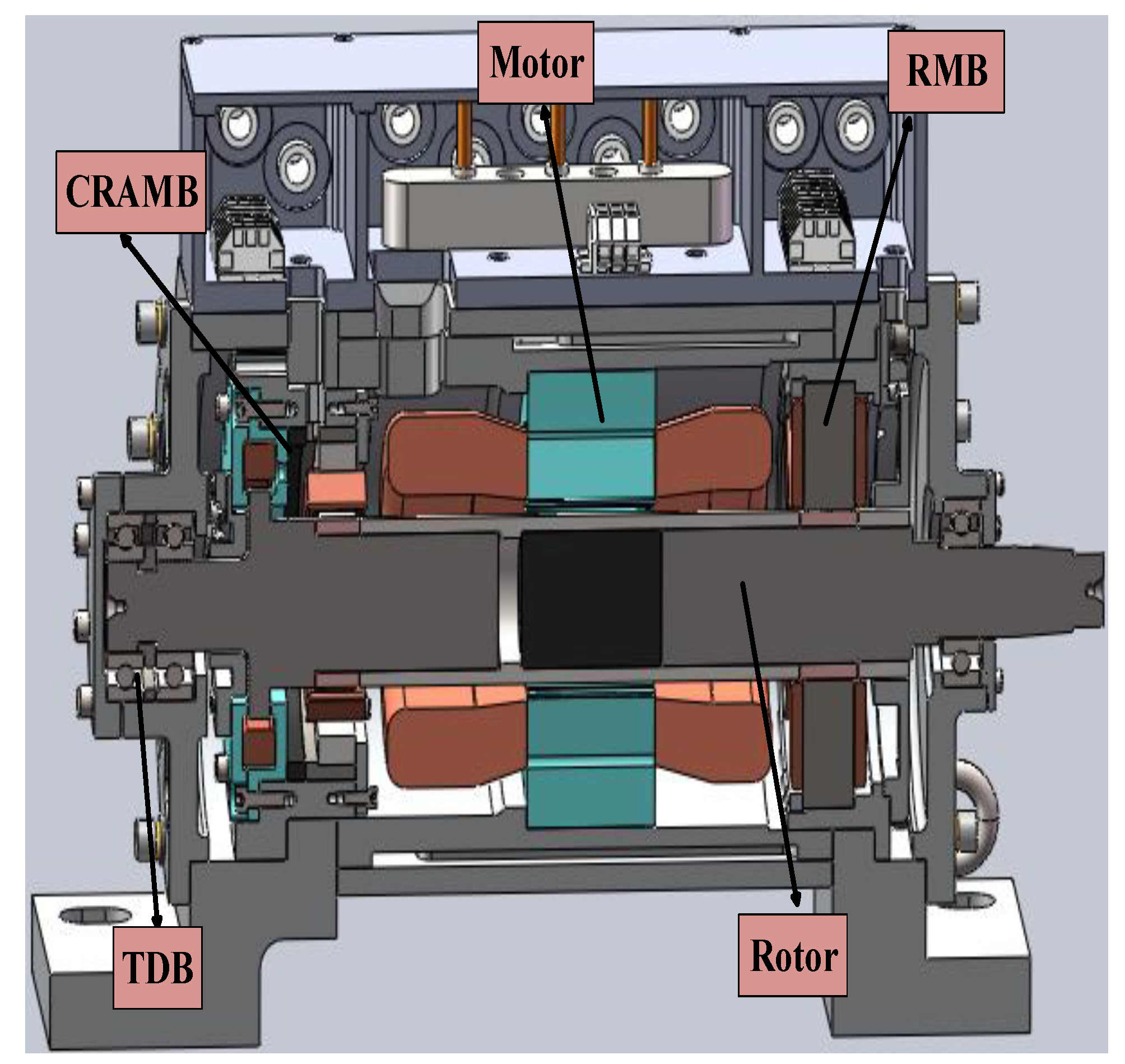
Accounting for above considerations, this paper proposes integrated design procedures and tests of the maglev BLDCM system, which consists of a high-speed rotor and three stators for radial magnetic bearing (RMB) [23,24], combined radial-axial magnetic bearing (CRAMB) [25], and a brushless DC motor respectively (Figure 1).Here, ideas about integration design interface and dynamic design parameters are put forward. Mechanical, electromagnetic and thermal aspects are all synthesized for their contradiction and integration. The motor design is set as the initial design entrance, to determine the outer and inner diameters of stator with other key parameters as dynamic design parameters. Then, MBs design is set as the interface for rotor, with MBs’ diameters and lengths determined. Constrains about rotor diameters among MBs and motor are established. With rotor dynamic, strength analysis and thermal design implemented, left dynamic parameters are set. Finite element method (FEM) is used for validating design model. A prototype of maglev BLDCM is manufactured, with 1.21 kW/kg power density, rotating to 33 kW, 55,332 rpm under load with drag system. The contradictions among various requirements and coupling effects among multiphysics are also reflected. Finally, design results obtained by above design methods are validated by drag test and MBs’ stiffness test [23,24,25] to finish closed loop of the whole integration design procedure. Integrated design method needs to be reflected.
2. Determination of Structure and Design Process
The innovation of this work mainly focuses on comprehensive consideration of BLDCM and magnetic bearings. The whole frame structure is determined based on mature experience. The design procedure is initialized from electromagnetic torque of motor and suspending force of magnetic bearings. The dynamic parameters are transferred among different design aspects to integrate engineering requirements of BLDCM and magnetic bearings. The design parameters are determined after strength and thermal analysis.
2.1. The Establishment of the Whole Frame Structure
Schematic section view of the maglev BLDCM system is shown in Figure 1, in which the structure of it is mature and applied in industrial compressor and blower [26]. The permanent magnet biased hybrid magnetic bearings are chosen for reducing power loss [21]. The CRAMB not only levitates rotor in radial direction with RMB, but also stabilizes it in axial direction. It is proposed for lessening axial size to improve rotor dynamic performance [26]. Thus, the volume is shrunk. Besides, the touch-down bearing (TDB) protects rotor from sudden falling. Sizes of MBs and motor are designed coordinately and integratedly, to satisfy the limits and requirements of whole system including rotor’s size, volume and multi-domain performance. For electromagnetic performance and dynamic performance, the rotor diameters for MBs and motor are integrated to design sequentially via dynamic variables.
Accounting for resonance suppression control of rotor vibration, cylindrical solid shape is chosen for permanent magnet (PM) instead of the block structure.
2.2. Design Methodology for Maglev BLDCM System
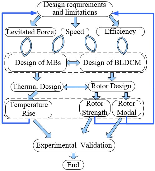
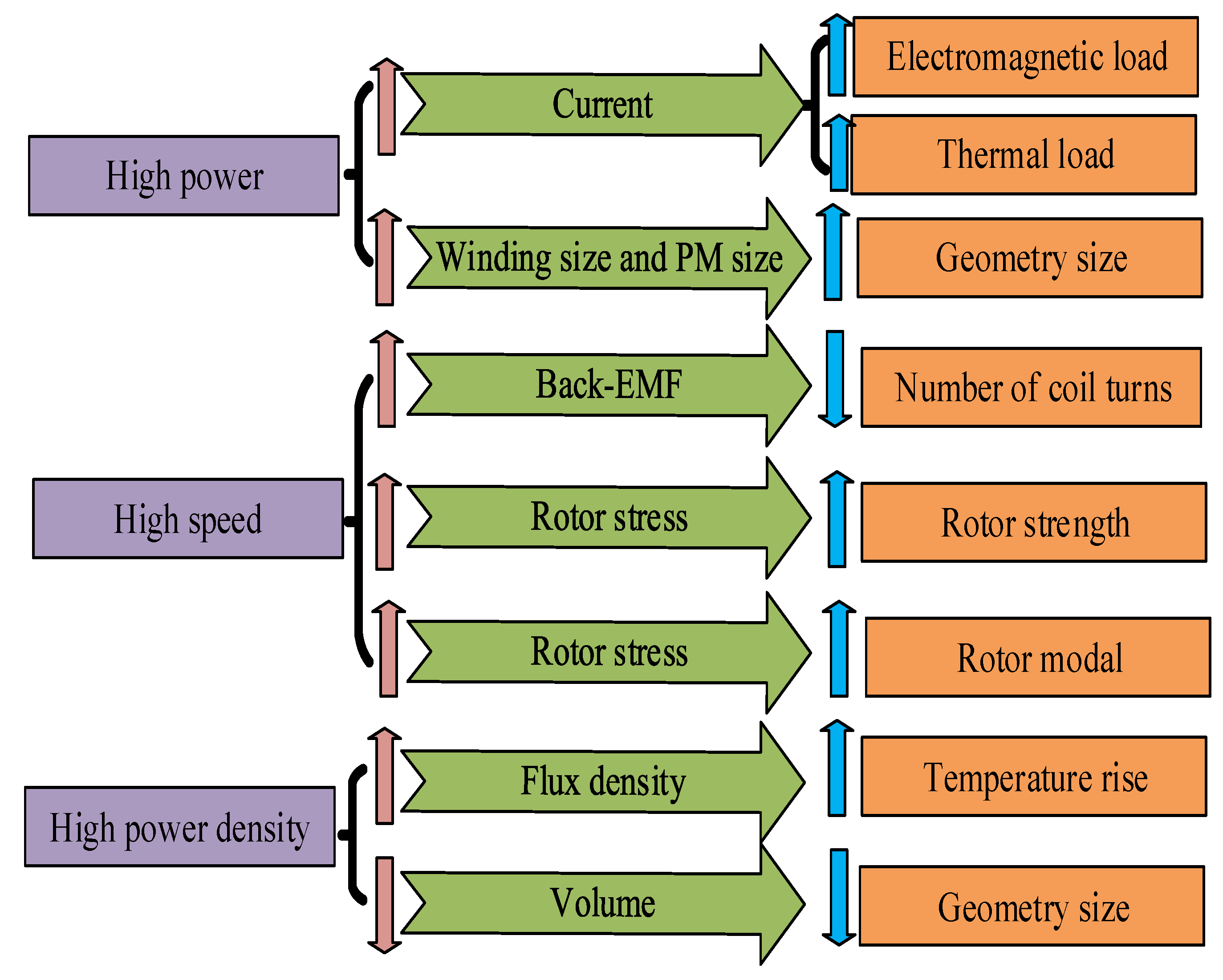
First of all, design objectives are selected, such as rotation speed, power density and other engineering design objectives also including the MB’s maglev force. Then, design limits are determined, such as limited strength of sleeve, temperature rise capacity, magnetic suspend force of MB, flux density in laminations of MB and BLDCM, and natural frequency of rotor. All of limits have contradictions. For example, demand for high-power leads to increases of winding coil numbers and permanent magnet volume, however, demand for high power density make decreases of them as Figure 2 shows. So they are to be solved via sequential design interfaces, by means of dynamic variables (marked as yellow color in Figure 3), which are mainly innovative integration strategy.
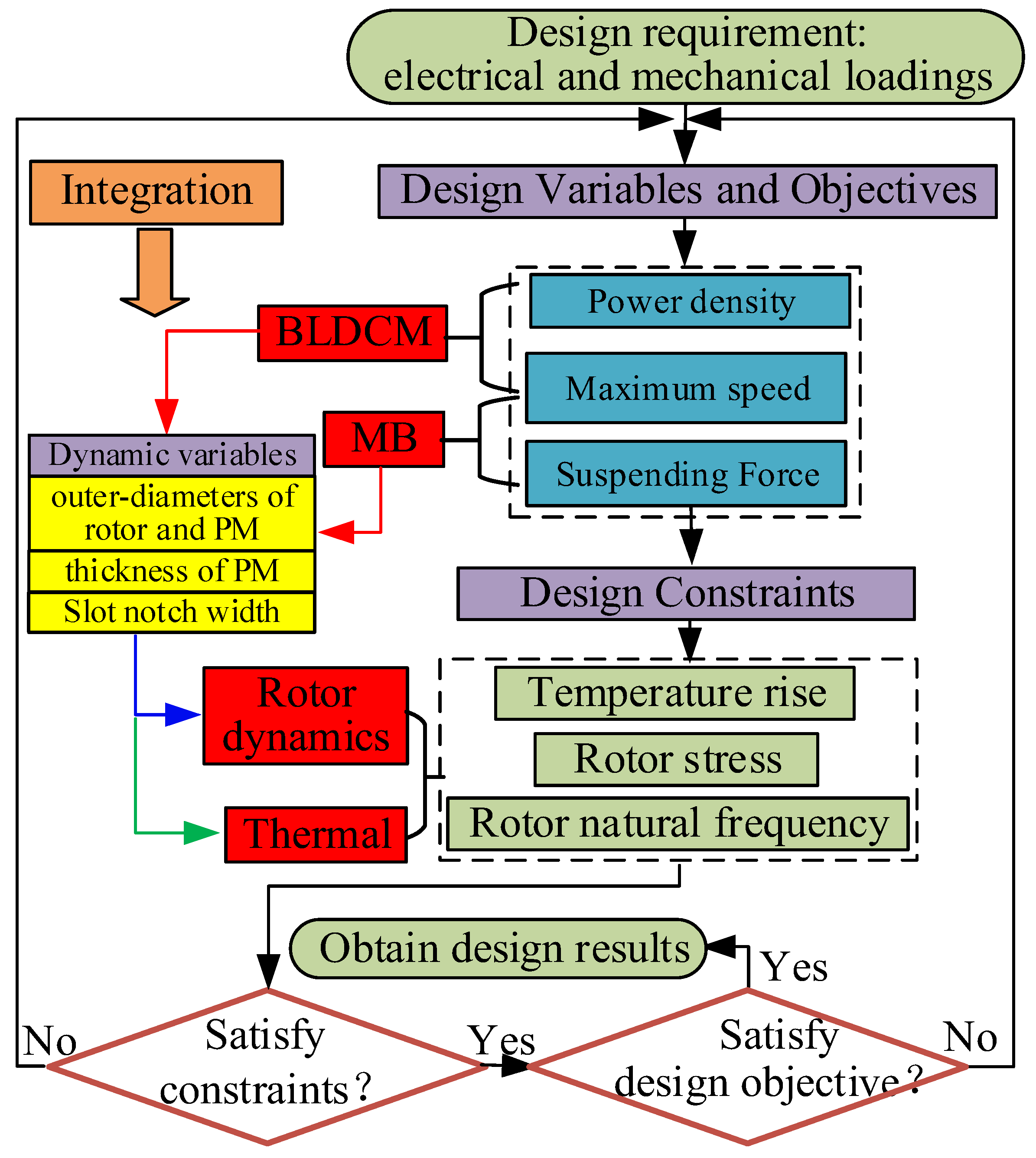
The integrated design strategy and the whole design process are express of the integration design idea, as Figure 3 shows. The entire design is divided into four main design modules (marked as red in Figure 3): brushless DC motor electromagnetic design, magnetic bearing electromagnetic design, rotor dynamics design and thermal design. In order to ensure the output performance such as electromagnetic power and bearing capacity of the whole system, BLDCM and MB design module are selected as the initial module to determine the size range of dynamic variables (marked as yellow in Figure 3), which are passed to other design modules. So the initial design of the motor and magnetic bearing is carried out first, the analysis model and related methods are used for the initial design of the motor [11,27], and MBs [24,28]:
Formula (1) is used for initial design of motor, where Dsi is determined based on demand for electromagnetic torque and power. The outer diameter and stator length are all set by tradition experience and electromagnetic torque requirement. Formula (2) is used for initial design of MB. It focuses on maglev force which is affected by stator sizes, as detailed in Section 3.2. Maglev force is determined by ki and ks, which are verified in Section 4.2.
Next, in order to keep consistency of outer-diameters for rotor’s different part, the corresponding outer rotor diameter for MB and motor is set as the dynamic variable. The thickness of the permanent magnet, which affects the output performance, and the thickness of sleeve that affects the mechanical properties of the rotor are also set as dynamic variables. The slot size of the motor stator is also set as dynamic variable since it affects magnetic circuit of motor and the eddy current loss of rotor. After these dynamic variables are transmitted to the rotor design module and thermal analysis module, their ranges are determined comprehensively via the combination of curves about performance parameters varied the rotor core diameter. These performance parameters are explained and verified by FEM in Section 3.3 including the rotor stress, modal, total loss, and bearing capacity. Performance curves in thermal design module [29] in Section 3.4 reflect relationships about harmonic distortion rate, output torque, temperature rise and power density varying by air-gap length. Above processes of selecting design points via dynamic variables, according to the curves of various performance parameters, are also the key innovation of this paper. Finally, dynamic variables are determined by means of the rotor dynamics design and thermal design modules. As a result, the design flow of the entire Maglev motor is completed and entered into prototype manufacturing, assembly and experimental testing, as described in Section 4.
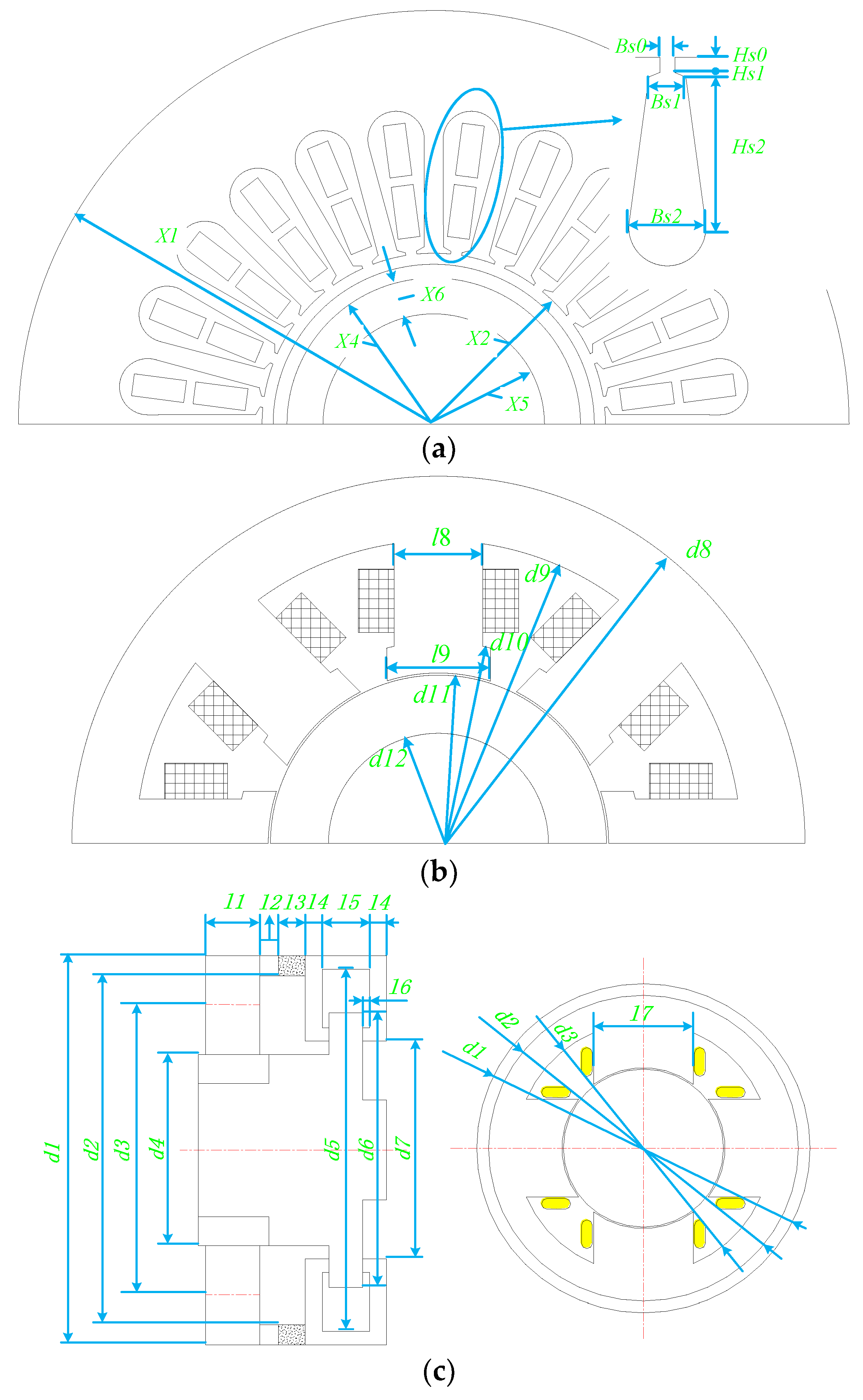
Specific design variables are shown in Figure 4. They are all critical dimensions such as inner diameter of motor stator and pole length of MB’s stator, which affect performance. Stator sizes are determined by Initial design. Rotor sizes and slot notch width are set as dynamic variables as mentioned above.
3. Design Process for Magnetic Levitated BLDCM
3.1. Electromagnetic Design of the High Speed BLDCM
For this BLDCM, the PM is magnetized in parallel with two poles for high energy density and well sine wave of air-gap flux density [19]. The BLDCM is designed for rated power 30 kW with highest speed 60,000 rpm. For coordinating electromagnetic and mechanical performance, the outer diameter and thickness of PM, and the outer diameter of rotor are set as dynamic variables, namely, key sizes left to determine in Section 3.3 and Section 3.4.
After initial design via Formula (1) for BLDCM [11], diameters and length of motor stator are set. Three dynamic variables left as Table 1 shows and they are to be solved with MB design and mechanical design in the following Parts.
With losses calculated by (4) and (5), the initial design parameters are defined as Table 1 shows. They are set as design interface for MBs design, rotor design, and thermal design, to coordinate various requirements interactively.
Back-EMF (electro-motive-force) of BLDCM Vemf, related to flux density and angular speed, is calculated by [30]:
B is the flux density analyzed by electromagnetic equations of BLDCM. The maximum value of B is calculated as 0.35 T. The result of back-EMF coefficients are 0.0677 Vs/rad, which would be validated via deceleration EMF test in Section 4.1. The general solutions for back-EMF and the flux density distribution in air-gap are introduced in [31] in detail. Then, electromagnetic field equation is modeled. In addition the eddy current expression, including varieties of harmonic components penetrating into the whole surface of the rotor, can be deduced from equivalent current sheet [31]. Thus, based on the Poynting vector theory, the corresponding average electromagnetic power loss in rotor is given by [27]:
Because of obvious influence on eddy current loss (ECL) exerted by outer diameter of rotor and slot notch width, these two variables are set as dynamic variables. They are to be solved by means of mechanical and thermal analysis in following parts, jointly.
Besides, core loss in stator can be calculated via [32]:
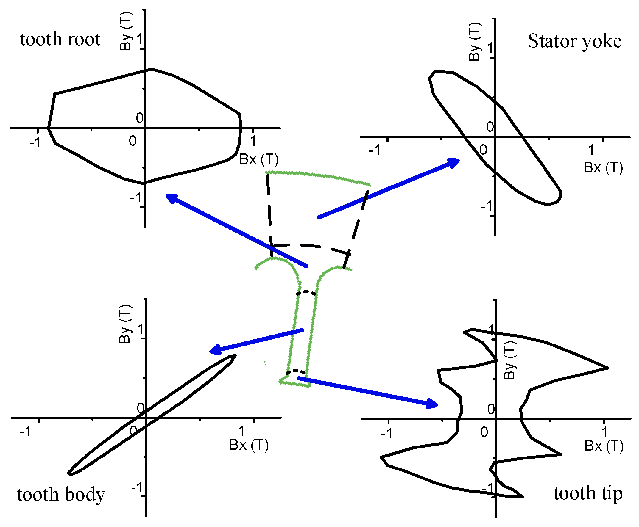
The stator is divided into several subdomains, such as yoke and tooth, to get flux discs, as Figure 5 shows. Then Bkmax and Bkmin are obtained via Elliptic Fourier operator on each elliptic loci of flux discs shown in Figure 5 by algorithm.
Since size of yoke like outer diameter has been determined in initial design via Formula (1), the slot sizes are determined here via core loss by (5). Kh, Kc, Ke, varying by frequency of excitation current and thickness of lamination, are got by BP fitting method as Table 2 shows.
In Table 2, the steel lamination made of 20WTG with 0.2 mm thickness is adopted, whose α = 1.62 in low frequency. By means of the Formula (4) and (5), and core loss coefficients in Table 2, the ECL and core loss can be calculated, which is used for estimate efficiency and thermal heat source.
Based on above calculation, as Table 3 shows, the ECL is 289 W, and the core loss is 187 W when the machine operates at 48,000 rpm. The loss values are set as the design interfaces for thermal design, because losses are heat source for thermal calculation and simulation. Temperature rise of motor got by thermal analysis completes the design loop to improve the integration design procedure (which has been shown in Figure 2).
In Table 4, x9 is left as dynamic variable, for it affects ECL obviously, so which is to be solved after thermal analysis.
3.2. Electromagnetic Design of the MBs
The actively controlled RMB and CRAMB are proposed for reducing power consumption, decreasing weight, increasing power density, and making dynamic performance of the rotor more robust reliability and active controllability.
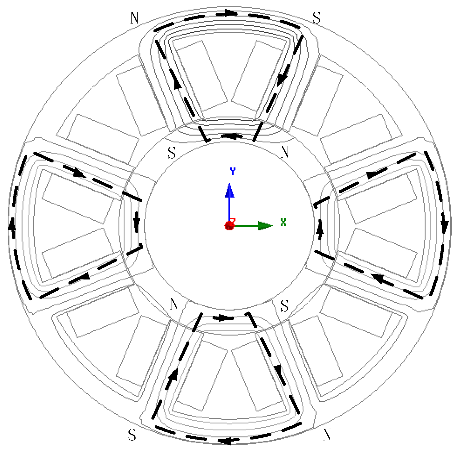
The RMB with electromagnetic bias is adopted. For control performance, the RMB stator consists of soft magnetic laminations with eight poles and coils spaced equally, of which two of them are comprised for one positive or negative direction pole in series. The RMB’s magnetic flux path and configuration are shown in Figure 6 [23,24,25]. The design model is established, as Formula (2) shows, based on that magnetic flux model, with design parameters shown as Table 5.
The simplified expression of radial force of RMB is obtained after its nonlinear terms over second order are neglected. Besides, this principle has also been applied for deduction of magnetic force of CRAMB in the followings. As a result, the total magnetic radial levitated force can be got by Formula (2), which is deduced from (6). Calculation values of current stiffness and position stiffness at rotor center position are 180 N/A and 587.1 N/mm respectively. They are to be validated by stiffness experiment in Section 4.2 to form a complete closed design loop for whole design procedure.
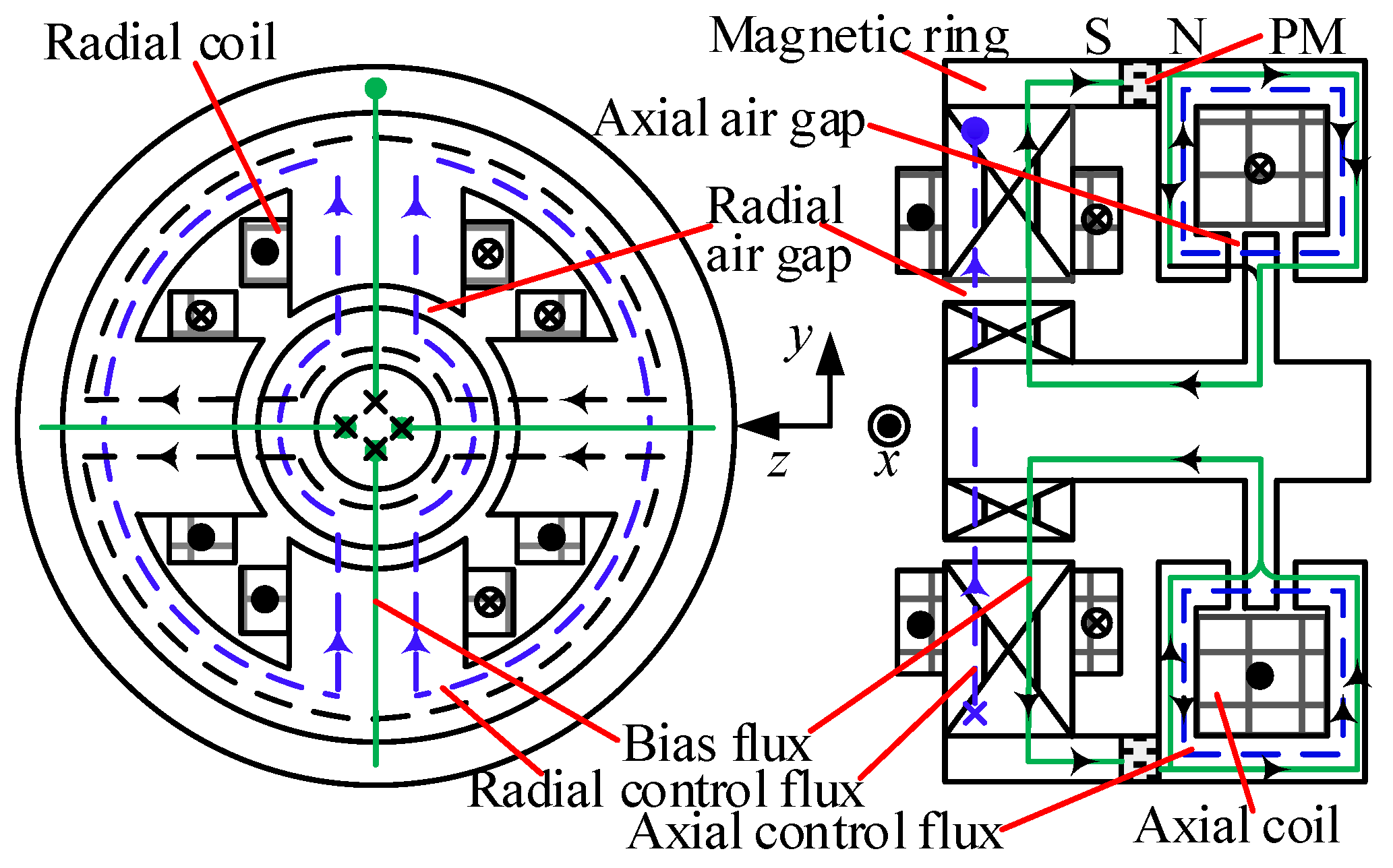
A CRAMB is proposed in this paper for its small thrust disk and axial size, and low wind friction power consumption. Figure 7 illustrates the configuration and flux paths in CRAMB. It consists of RMB and thrust MB (TMB) units. Radial coils and axial coils generate control flux (indicated as blue dotted line), while the PM provides bias flux (indicated as green line). The similar structure of this CRAMB has been presented and analyzed in [21]. Its RMB unit is also designed by (2). Design parameters of CRAMB are shown in Table 6.
Magnetic forces of CRAMB in radial and axial direction are all deduced base on the following formula [23,24,25]:
Obtained by relationships that the bearing force varied by coil currents and rotor displacement for RMB and TMB units of the CRAMB respectively via FEM, the predicted current stiffness and displacement stiffness of the RMB unit at rotor center position are 137.3 N/A and −692 N/mm respectively. The predicted current stiffness and displacement stiffness of the TMB unit at rotor center position are 261.5 N/A and −1086 N/mm, respectively, validated by experiment. For rotor weight less than 8 kg, aforementioned current stiffness value promises that the rotor can be levitated fast and stably.
3.3. Design of High Speed Rotor Considering Its Dynamics
Since high speed rotor is crucial part of high speed machine, the stress or strength limitation is influenced by materials and craftwork of the assembly of rotor enormously and inherently. And rotor mode limitation should be considered here. For active vibration control of rotor, the first order bending mode frequency of this high speed rotor should exist far from the operating frequency (60,000 rpm) for stable rotation.
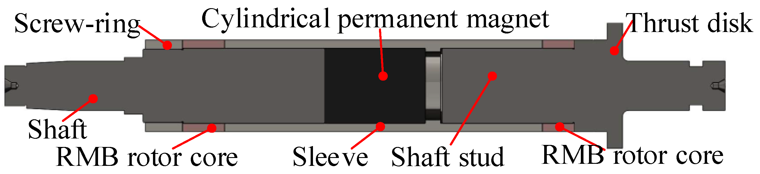
The configuration of this maglev high speed rotor is shown in Figure 8 in this work, and the material of every part in it is listed in Table 7. A pre-compressive stress is applied on the permanent magnet, by using an interference fit with sleeve to reduce the tensile stress against high speed centrifugal force. Total equivalent stress must be restricted below the yielding point of rotor assembly material throughout the whole speed range. The value of interference fit is 0.18 mm, which is adopted between the cylindrical rotor parts and the sleeve.
After the rotor is scattered into many finite units, the rotor mode can be calculated based on vibration equation:
Solution existence condition of ωr is that the determinant of displacement impedance matrix as Z is 0, that is:
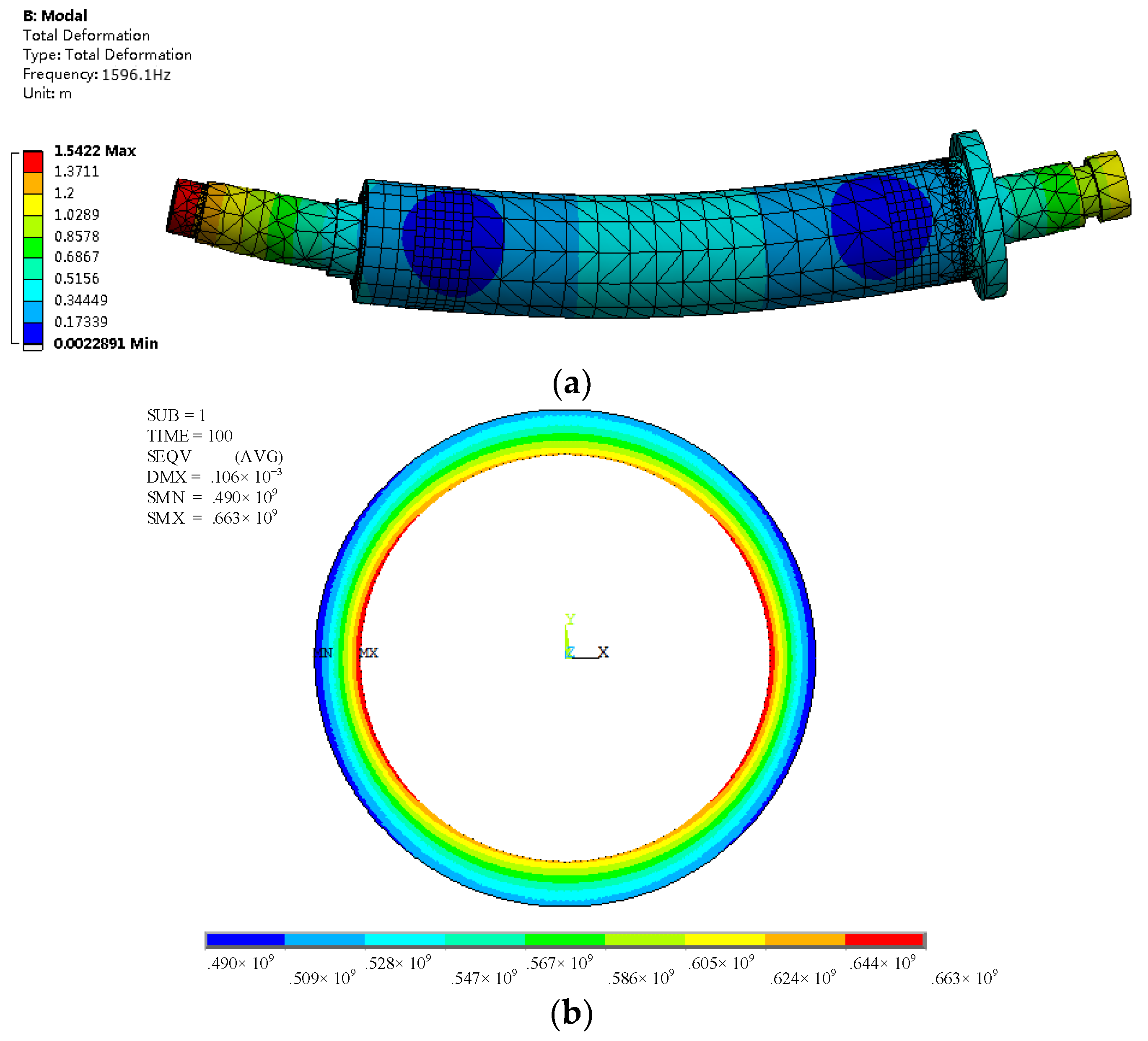
While the mr, cr and kr are all positive definite matrixes, eigenvalues of it λi2 can be solved, of which λi is mode. First order bending mode is calculated by transfer matrix method to determine initial rotor with stress analysis together. FEM results of first-order bending mode is used to validate the effectiveness of above analytical model. The CAD model of rotor assembly is imported into ANSYS simulation interface for rotor modal, then mesh and solution of FEM model are completed. Its first-order bending mode is 1596 Hz calculated by FEM, while the tested result is 1590.7 Hz by an excitation method (flexible free suspension of rotor), where error is less than 1%. Besides, the deviation between the inertial spindle and rotating spindle is very small because of the better off-line and on-line dynamic balance operation, so the eccentricity led by rotor unbalance can be neglected, which has been validated by experiment.
The equivalent Mise stress of rotor is calculated based on Von-Mises yield criterion. The crucial stress evaluation generates at the interface between sleeve and PM. So, the stress analysis of PM is shown as the followings:
Based on above deduction, the analytical expression for stress of permanent magnets under practical conditions can be obtained, with impact of assembly, centrifugal and temperature increase are all considered.
Thus, the total equivalent Von-Mises stress of sleeve is:
which should satisfy the constraint:
where n = 1.3. All stress components, including the static assembly stress and the dynamic stress, are shown as:
where r is radius of PM or sleeve. ps is assembly pressure caused by interface fit. ρm is the density of PM, 7.4 × 10³ kg/m3, or sleeve, 8.2 × 10³ kg/m3.
In assembling process, the sleeve is heated to 500 °C and lately cooled while the shaft stud, the RMB rotor core, and the shaft are placed at the assembly final position. The temperature during the assembly process is controlled under the one leading to demagnetization of PM, with mechanical performance also been considered. Here the thermal stress, caused by temperature increase, can be calculated as:
In (13), motor’s temperature rise under load is obtained by thermal calculation in Part. D via thermal FEM to get maximum temperature rise. Here, the temperature rise ΔT is selected as the maximum value among the assembling temperature, the under-load temperature and demagnetization temperature. Thus, with Formula (16), the design interface between mechanics and thermal is constructed based on thermal stress and .
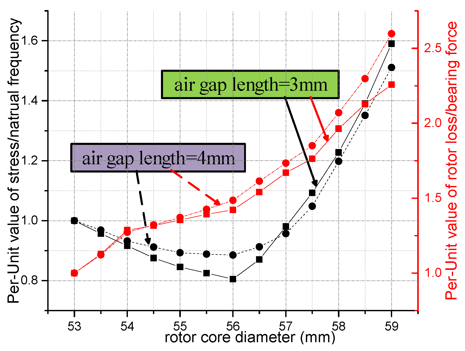
To obtain integrated optimal design results, synthesis of different performance of rotor among several design aspects is necessary, as Figure 9 shows this selection of design point of rotor diameter. As can be seen in it, the ratio of stress to natural frequency, just as , however, the Per-Unit value of it, , is used to eliminate the effect of dimension here, as the left black vertical axis shows, corresponding to two black curves in Figure 9, where is the initial value when the rotor diameter is 53 mm, thus, the Per-unit value of the ratio of rotor loss to bearing force is represented by the right red axis, also corresponding to red curves in Figure 9, namely . Thus, these two Per-Unit values are all designed to minimize, so out-diameter of rotor is selected as 56 mm with representative air gap length 3 mm and 4 mm under comprehensive consideration. Besides, the variation tendency of them, and each respective design objective and aspect, all influence the selection point. So, dynamic variables of rotor are further determined. After above optimal selection, the air gap is 3 mm, where rotor loss is 1970 W at 60,000 rpm, radial bearing force can reach 270 N with normal amplifier. Besides, from Figure 9, the design sensitivity of to the diameter of rotor has little variation approximately, while, the sensitivity of begins to increase obviously when the out-diameter of rotor starts to increase from 57 mm, which is the inflection point for sensitivity. In the light of robust design, the out-diameter of rotor may affect the performance more obviously from 56 mm.
With final design, the contact pressure in an interference fit is analyzed by means of the numerical simulations using FEM (using Ansys 14.0 to establish load and boundary condition). Thus, the equivalent effective stress contours of the sleeve are shown in Figure 10b. The maximum equivalent stress of sleeve is 663 MPa, with safety factor being 2. Based on the same FEM process, the maximum equivalent stress of the permanent magnet is 21.8 MPa with safety factor 3.67.
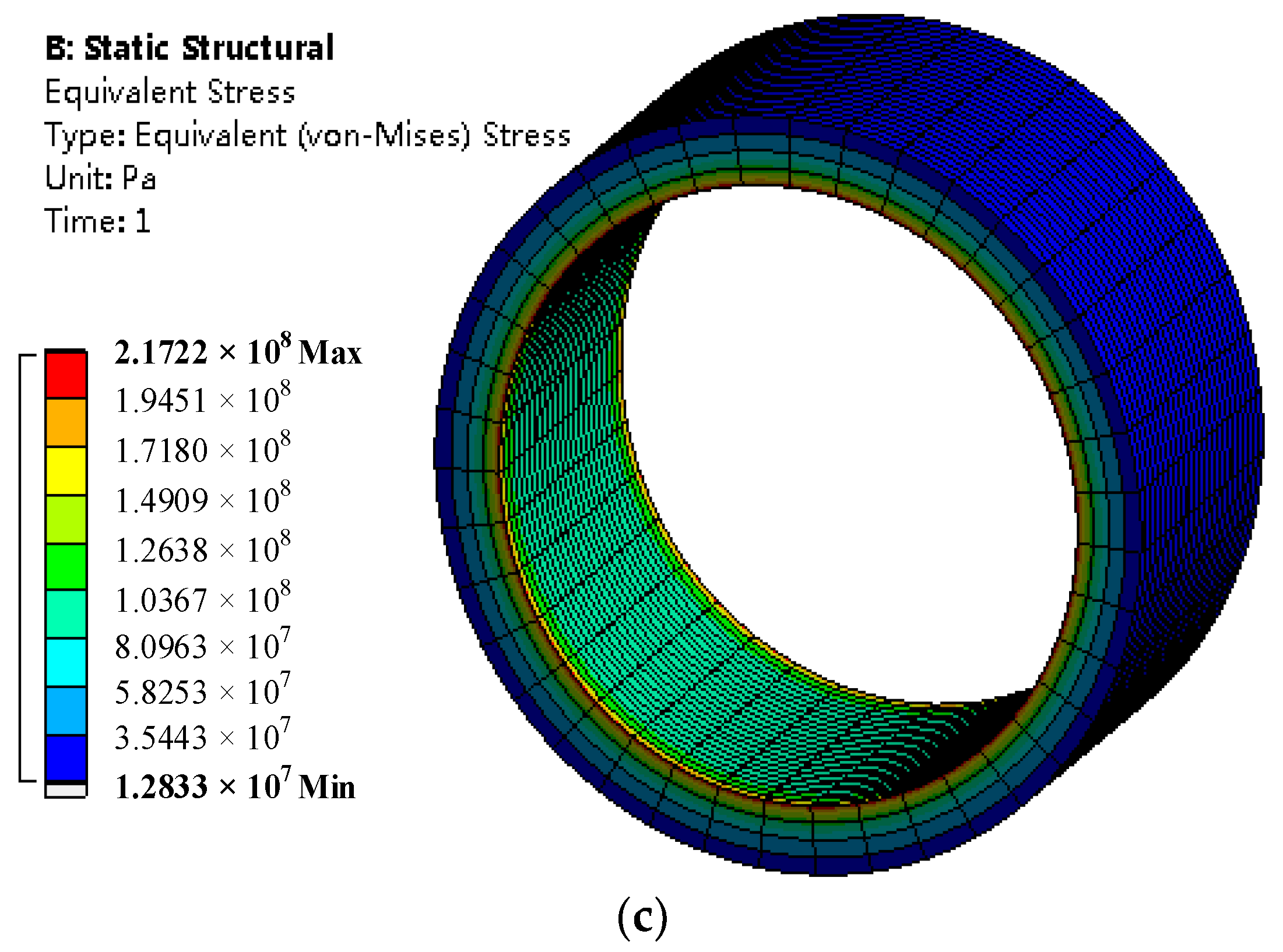
Figure 10c shows the equivalent effective stress distribution of the RMB rotor core. The maximum equivalent stress of it is 217 MPa. The yield stress in rotor core of the RMB is 380 MPa. The safety factor is 1.75.
3.4. Thermal Design Considering Electromagnetic Aspect
The crucial requirements and limitations for high power density and high speed motor could come down to the temperature sustainability and thermal reliability. High current density in coils and volume limitations of BLDCM could lead to high temperature rise, thus, also lead to thermal design selection as for high speed motor. Besides, the cooling ability decides the thermal property of BLDCM, which is influenced by air gap lengths of motor and MBs, with the air cooling and water jackets improving it, which are all set as design feedback interface for structural design. Temperature rise of each part in motor system should be below the allowable temperature rise with permitted allowance reserved.
FEM process of three dimensional steady thermal field and fluid field of this BLDCM deserves fundamentals of heat transfer, namely, with regard to analyzation of steady thermal field, steady heat conduction equation does not contain the time term, meanwhile, including heat source and medium, which can be expressed as the shown below:
The boundary condition in adiabatic surface is , while in radiating surface is .
After heat transfer coefficients being determined, with every heat source and heat generation rate has been obtained (as Table 8 shows) and assigned to corresponding area, temperature rise can be got by (18) via FEM. Here, thermal analysis takes the form of validation by FEM for the final determination of dynamic variables as the final interface.
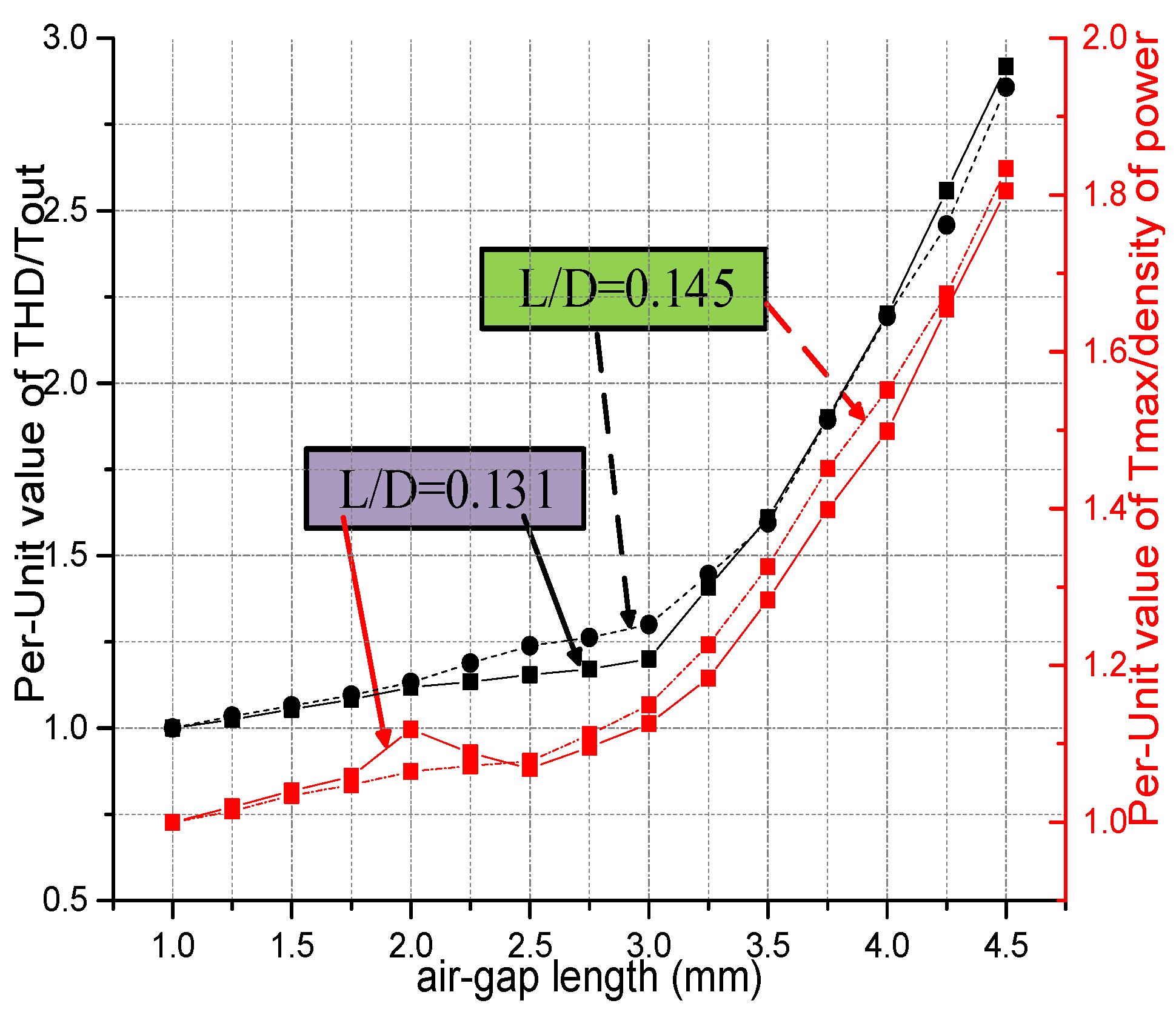
With similar ideas to Figure 9, synthesis of electromagnetic, thermal, and power performance is implemented as Figure 11 shows for selection of design point of air gap length. In the same way, Per-Unit values of the ratio of total harmonic distortion (THD) to output torque and the ratio of maximum temperature to density of power have the same corresponding relationships with vertical axes as the ones of Figure 9. Minimum of Per-unit values are optimal for design, considering with rotor dynamics requirements, 3 mm air gap length is selected, approximate to inflection point, with different ratios of length of rotor to diameter (as L/D in Figure 11, 0.131 is the optimal value) are considered. While THD = 9.6%, Tmax = 139 °C. Besides, from Figure 11, sensitivity about air-gap length begins to increase immediately when air-gap value is 3 mm. It affects performance remarkably when its value is more than 3 mm. It also can be seen from the sensitivity that the air-gap length is a key parameter that it should be set as the dynamic variable to coordinate every design model and determine the overall performance of the high speed BLDCM.
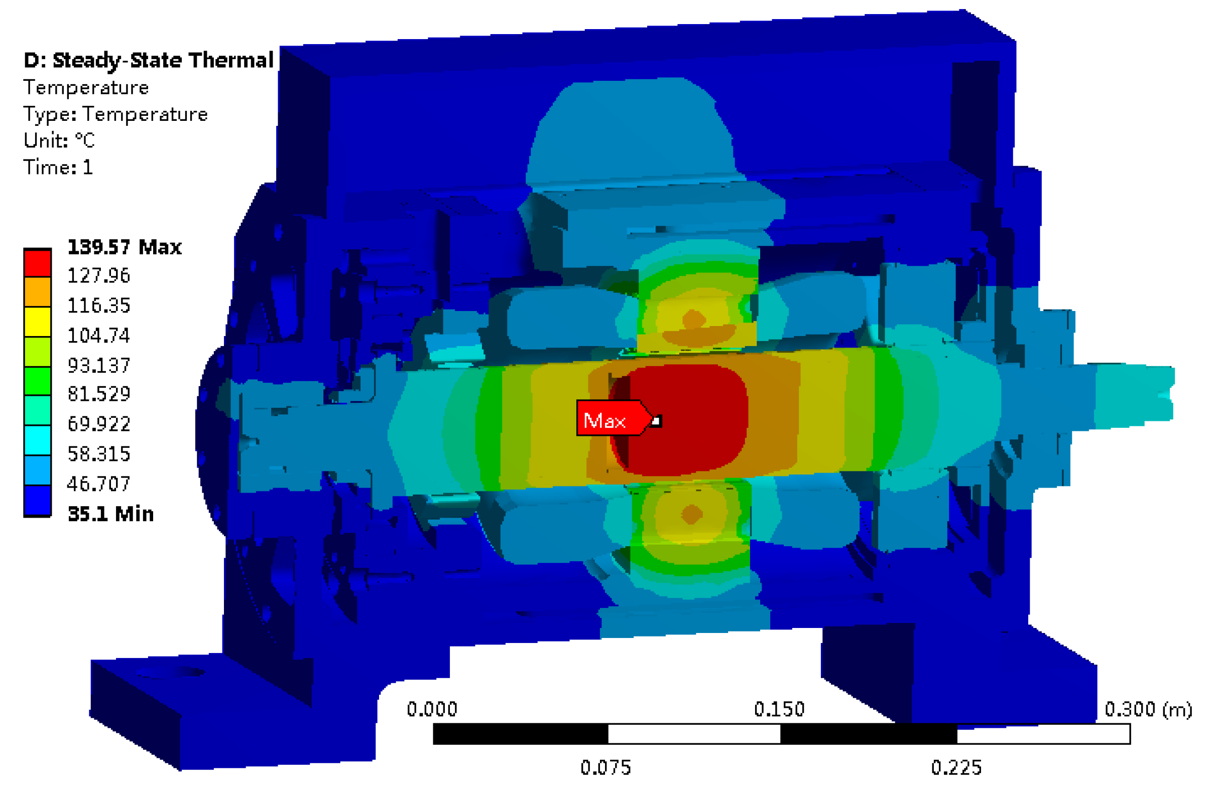
Accounting for boundary conditions, with assignment of those heat source values in Table 8, the thermal solution can be obtained by FEM, however, in which heat transfer coefficients (HTC) are key values for it. Definition of HTC in air gap and jackets are described in [29] by computation fluid dynamics (CFD) method, with others are defined by material properties, empirical formulas, and values. The highest temperature is 139 °C located in the positive center in cylindrical PM as Figure 12 (in lower right corner) shows. The temperature of sleeve and PM can be substituted into (22) to validate their thermal stress to make thermal-mechanical coupling. Besides, the highest temperature of PM is beyond its demagnetization point. While at of the stator is beyond 90 °C (in upper right corner in Figure 12), which can promise the insulation of the winding below the safety value. Thus, the final values of the dynamic optimal variables are determined after the thermal analysis and selection process, based on Figure 11 as Table 9 shows.
3.5. Thermo-Structural Verification
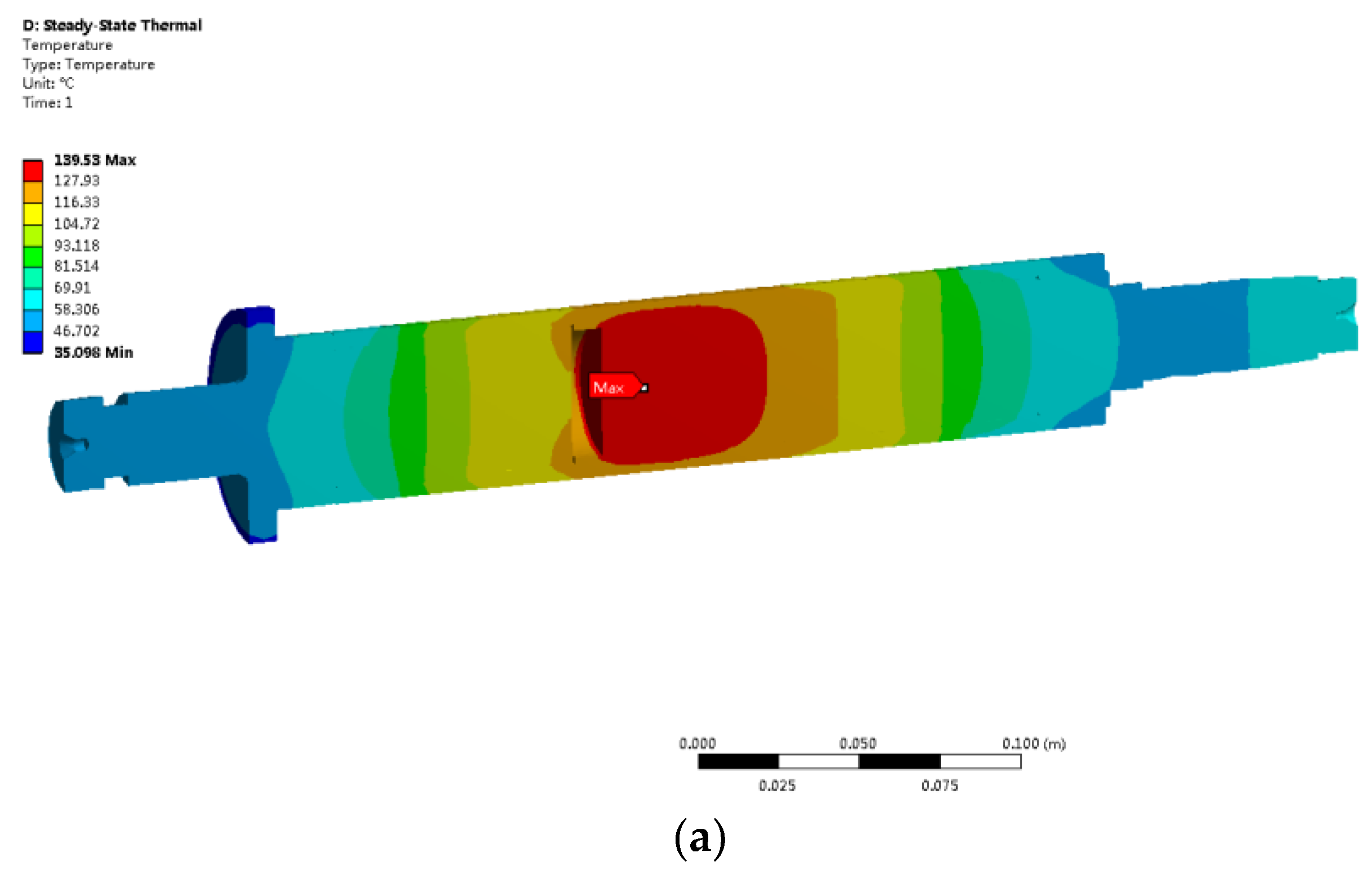
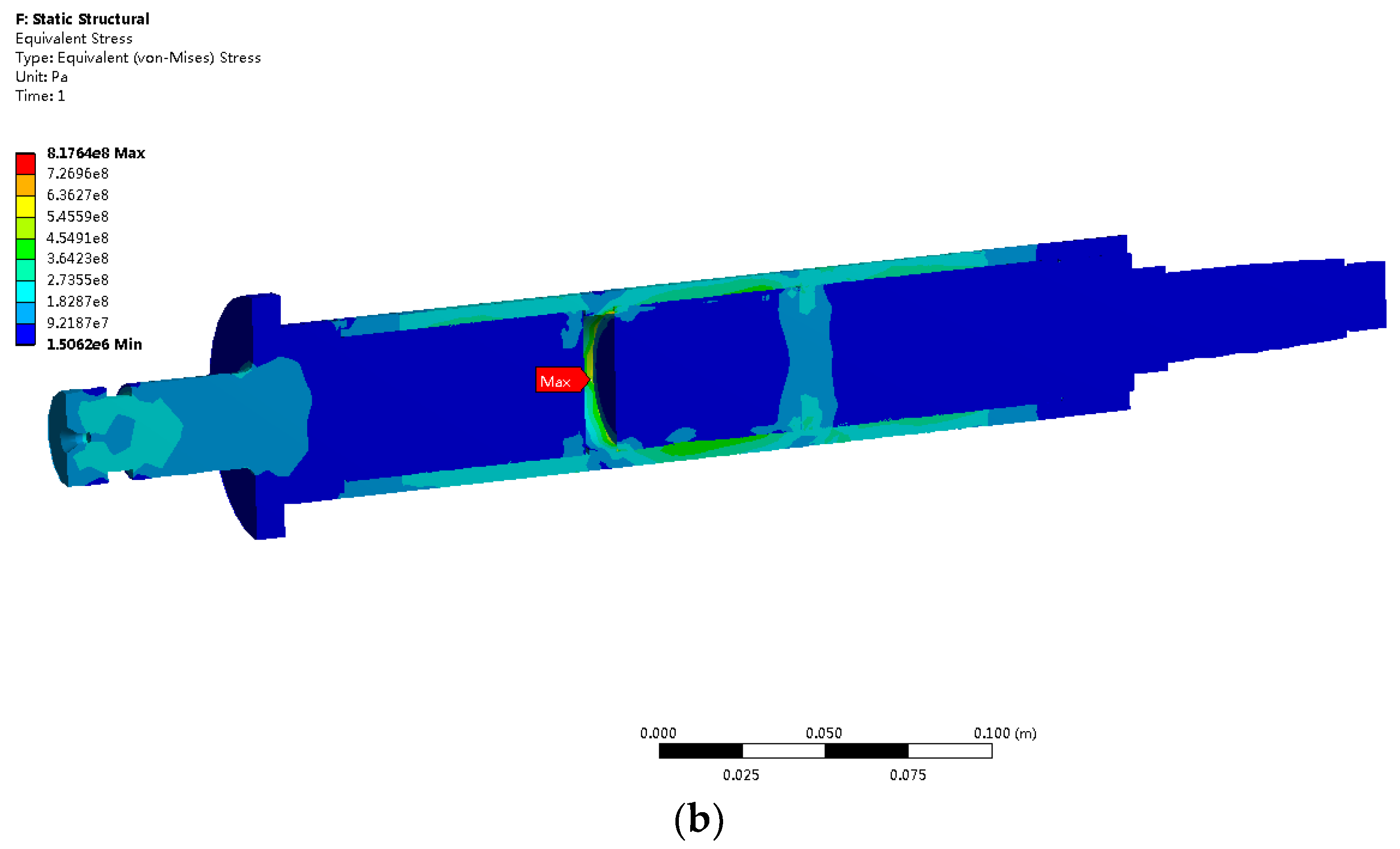
Thermo-structural coupling analysis is implemented by Ansys software. Accounting for the characteristics of material and the computation effectiveness, the sequential coupling method for Thermo-structural analysis is adopted. The temperature field is solved first. The temperature distribution of rotor is shown as Figure 13a and the maximum temperature value of rotor is 139 °C as Section 3.4 mentioned. Then, the temperature data of element nodes are transferred into the stress analysis mode as boundary condition. When the constraints and velocity condition is assigned to the model in stress analysis mode, the stress distribution of rotor is solved as Figure 13b shows. The maximum stress of rotor under maximum temperature achieves 817 MPa, with safety factor being 1.4. So, the rotor still maintains qualified degree of safety even its maximum temperature rises to 139 °C under rated load with steady state.
4. Experimental Validation Based on Prototypes
4.1. The High-Speed BLDCM Prototype and No-Load Test
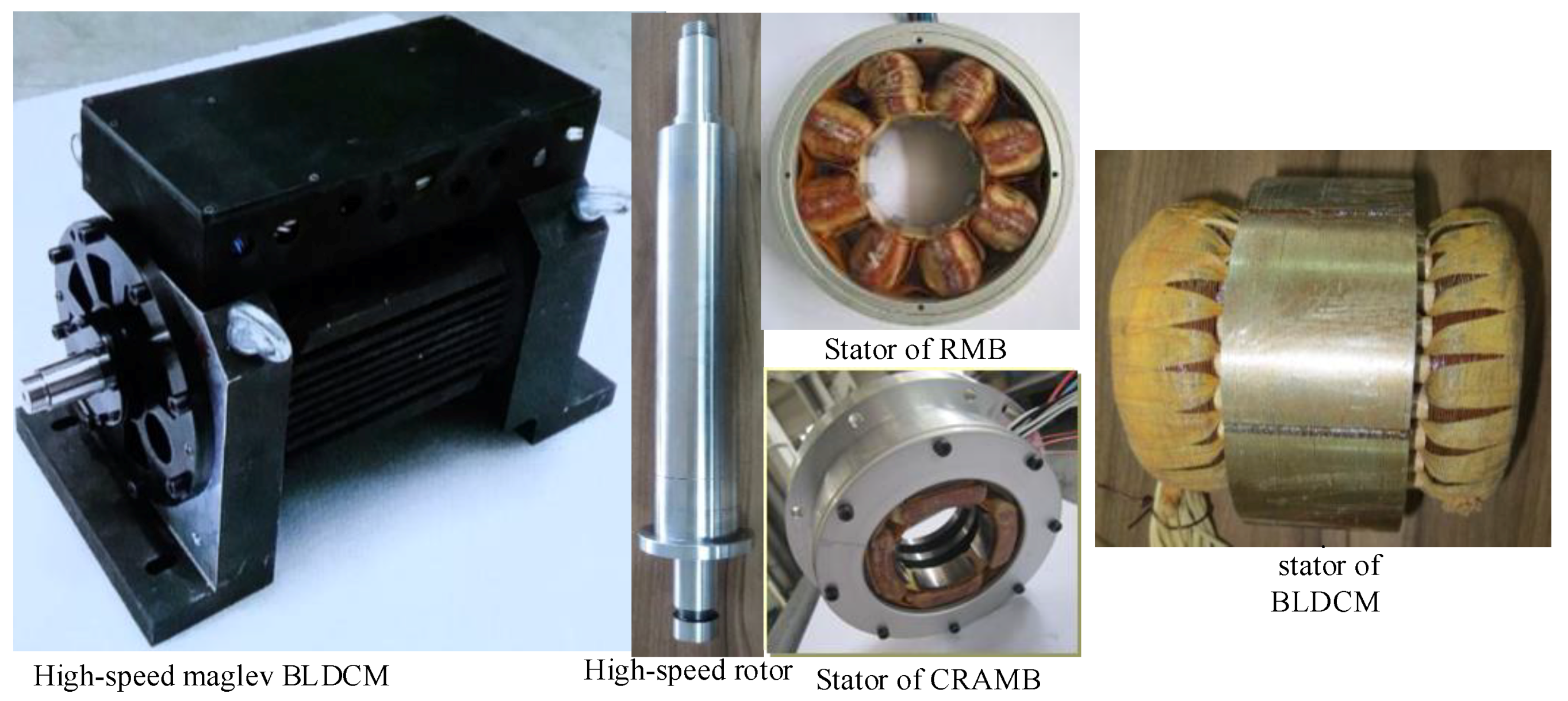
Figure 14 shows the high speed BLDCM system with a high speed rotor and stators for BLDCM, RMB and CRAMB. Total mass of the assembly is 41 kg. In addition, no-load experiment is operated to validate the design of the system, including the rated power, the maximum speed, and the stability characteristics of the MBs-rotor system, etc.
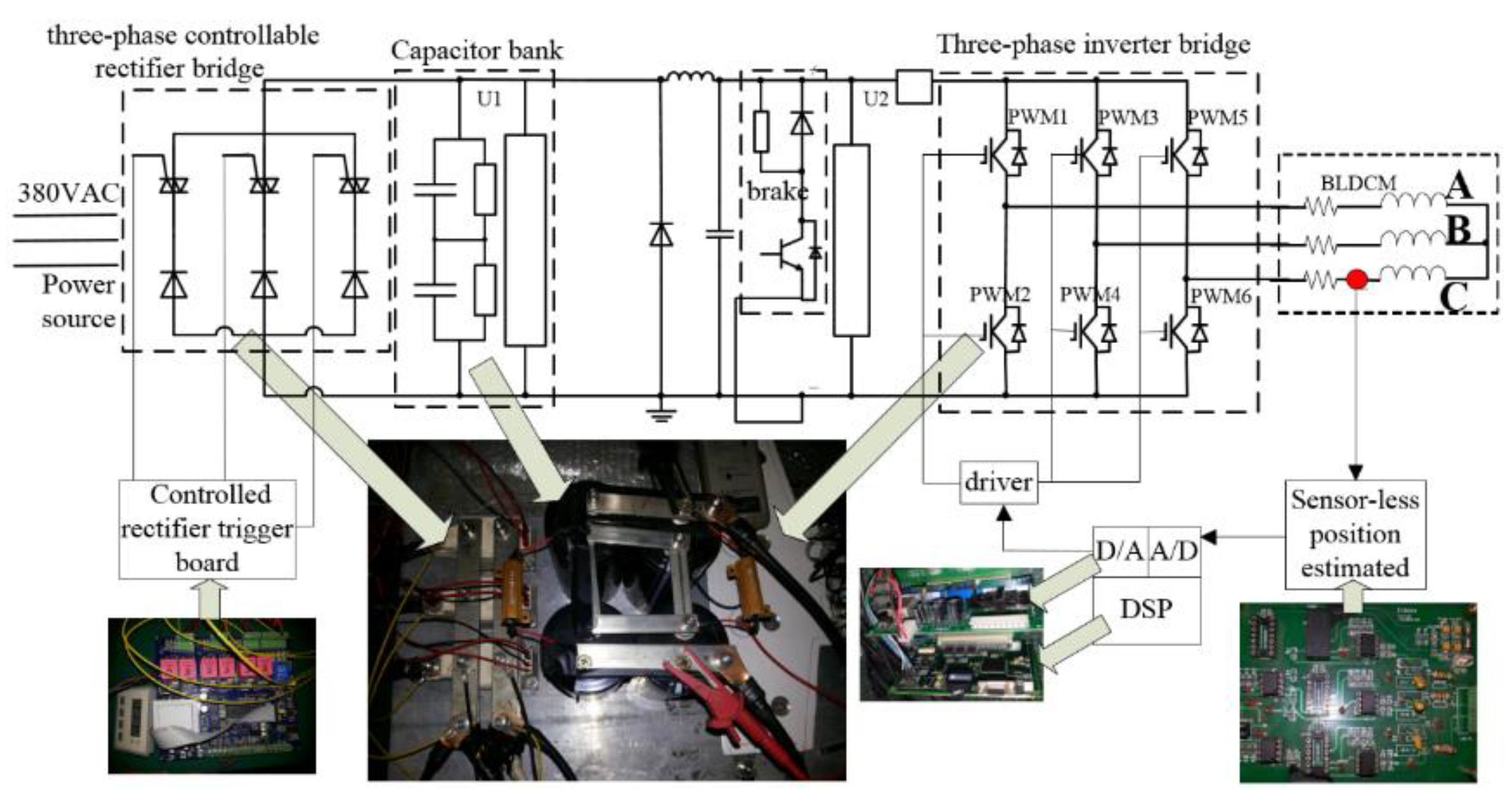
Figure 15 shows the control circuit sketch and practicality about inverter, control board, and signal processing board. To satisfy with the high speed characteristics of BLDCM, the controlled rectifier is selected. So when the motor is driven to the synchronous status based on sensor-less control strategy, the motor could be accelerated by increasing DC-bus voltage via controlled rectifier. With DC-DC converter being got rid of, the advance communication strategy is adopted, because the deep filter for high speed and high frequency would cause obvious signal delay. The motor adopts sensor-less position estimated strategy to obtain rotor angle position. Based on this control system, the acceleration and deceleration test for BLDCM is carried out.
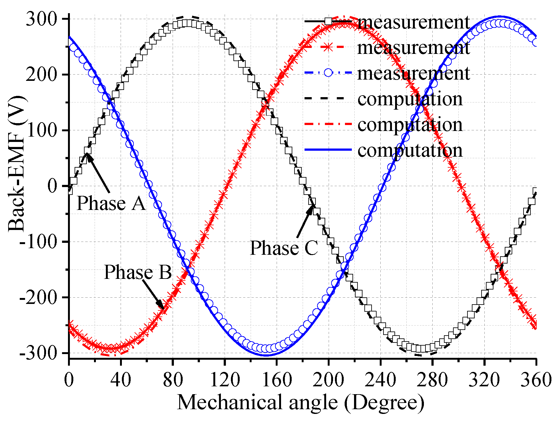
Three-phase back-EMF waveforms are shown in Figure 16, where computation results (by FEM) are compared with measurement (by deceleration test after no-load acceleration) when the BLDCM works at 60,000 rpm. Measured results of back-EMF is obtained by deceleration test, agreeing well with the one got by FEM results, with error between them 4.2%.
The key parameters of BLDCM is shown in Table 10.
4.2. Experiment of Suspending Performance of AMBs
The linearized models for MBs is set to define its controller parameters at equilibrium position [7]. Thus, the current-force and displacement-force stiffness become important for it determining the suspending capability, active resonance suppression control ability, and other dynamic performances. According to the linearized model of the AMB [23,24]:
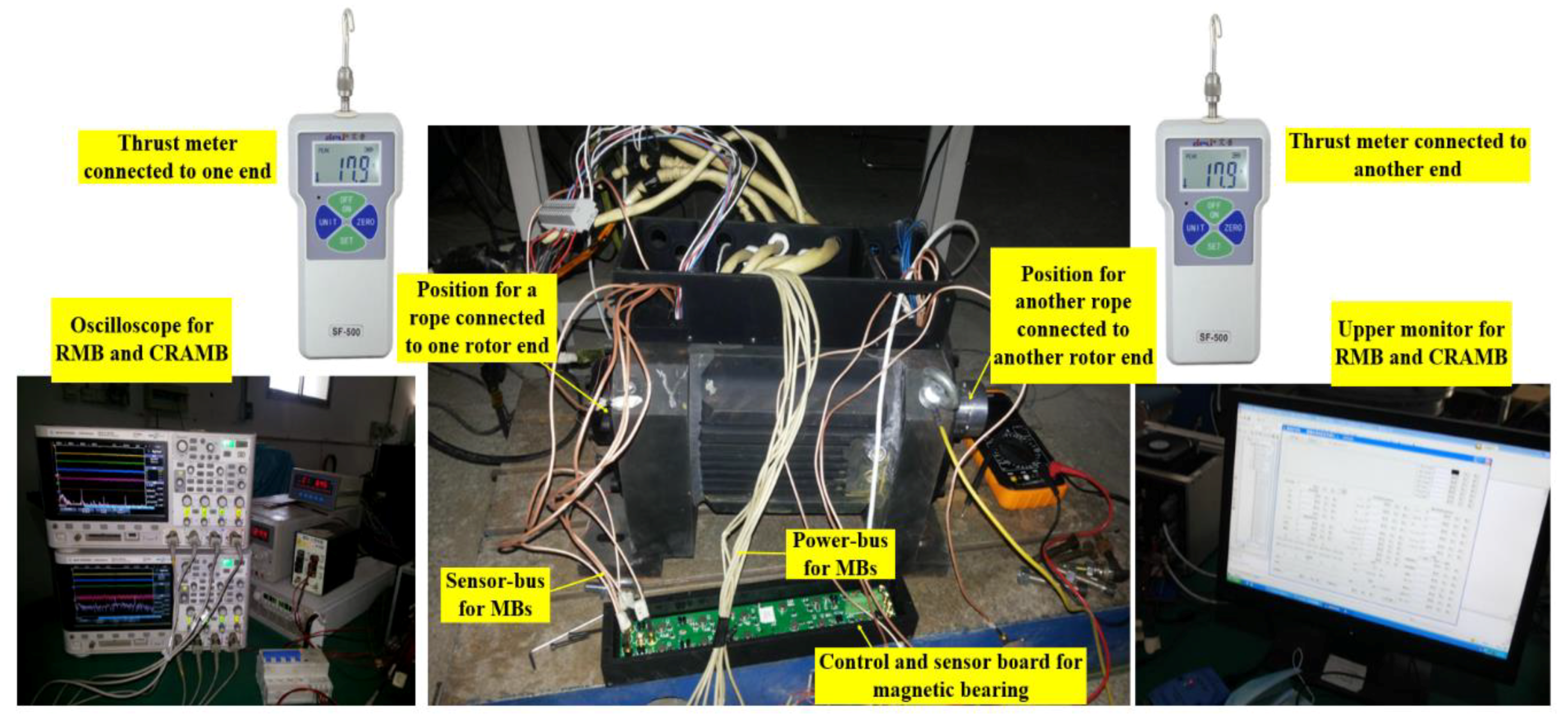
where fb is the bearing force, ks is the displacement stiffness, ki is the current stiffness, x is the rotor displacement, i is the control current. When the rotor is suspended in the original position, the exterior force can be exerted on the rotor by the pull meter, and the control currents of AMBs is adjusted to keep the rotor suspended around the original position. The forces can be recorded by the thrust meter, and the control currents can be tested by oscilloscope. The test platform and related practicality is shown in Figure 17. The displacement can be recorded by oscilloscope, with the current recorded by upper monitor as Figure 17 shows. Series forces with corresponding control currents can be obtained as shown in Figure 18a and Figure 19a. In addition, control currents data here recorded are those subtracted by the ones used to overcome gravity of the rotor.
The displacement-force stiffness is calculated by [25]:
where i/x is the slope of displacement-current curve. It can be seen from Figure 18b and Figure 19b, when no force exerted on the rotor at equilibrium position, the control currents are not equal to zero caused of a little bias between the magnetic center and the gravity center of the rotor, which does not influence the current-force and displacement-force stiffness. Based on the data tested in radial and axial directions, the linear fitting curves can be obtained with corresponding slopes. Thus the displacement-force stiffness can be obtained via the slope values and corresponding current-force stiffness values obtained by former process are substituted in (16).
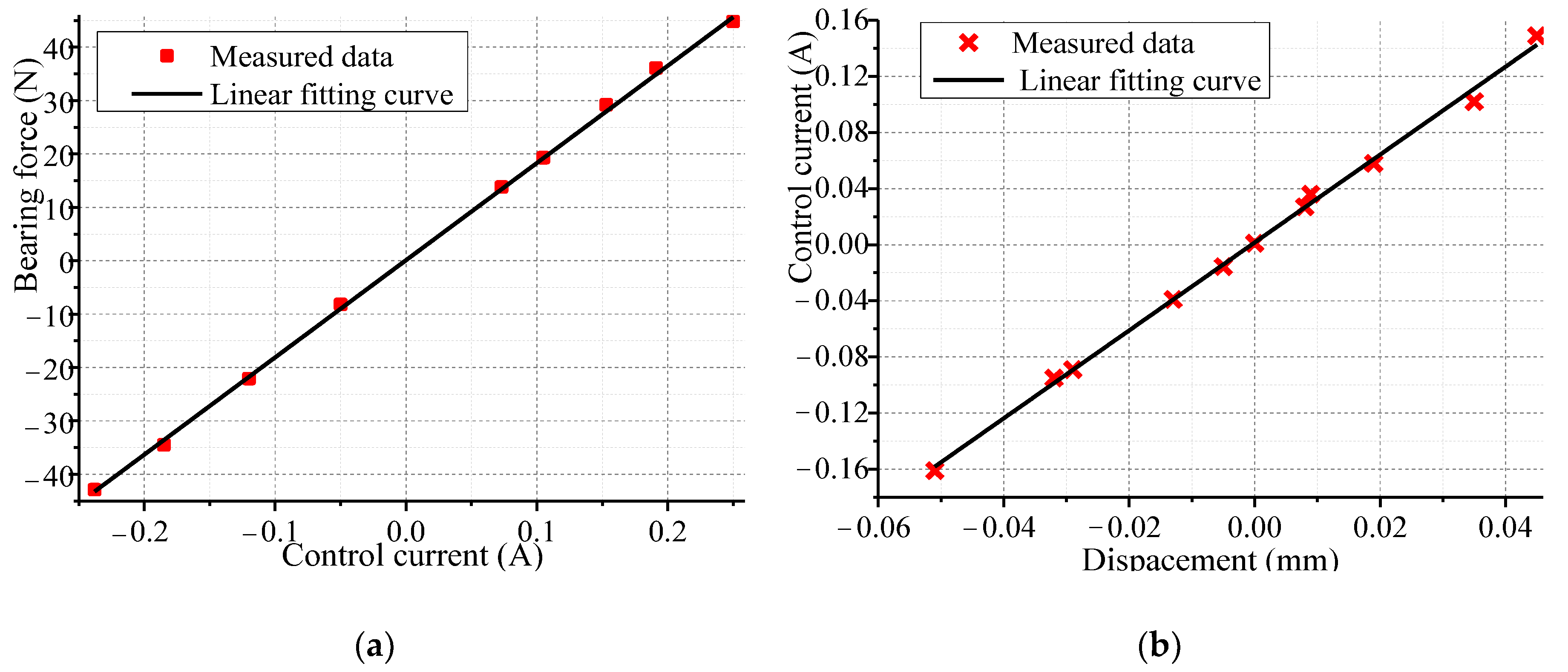
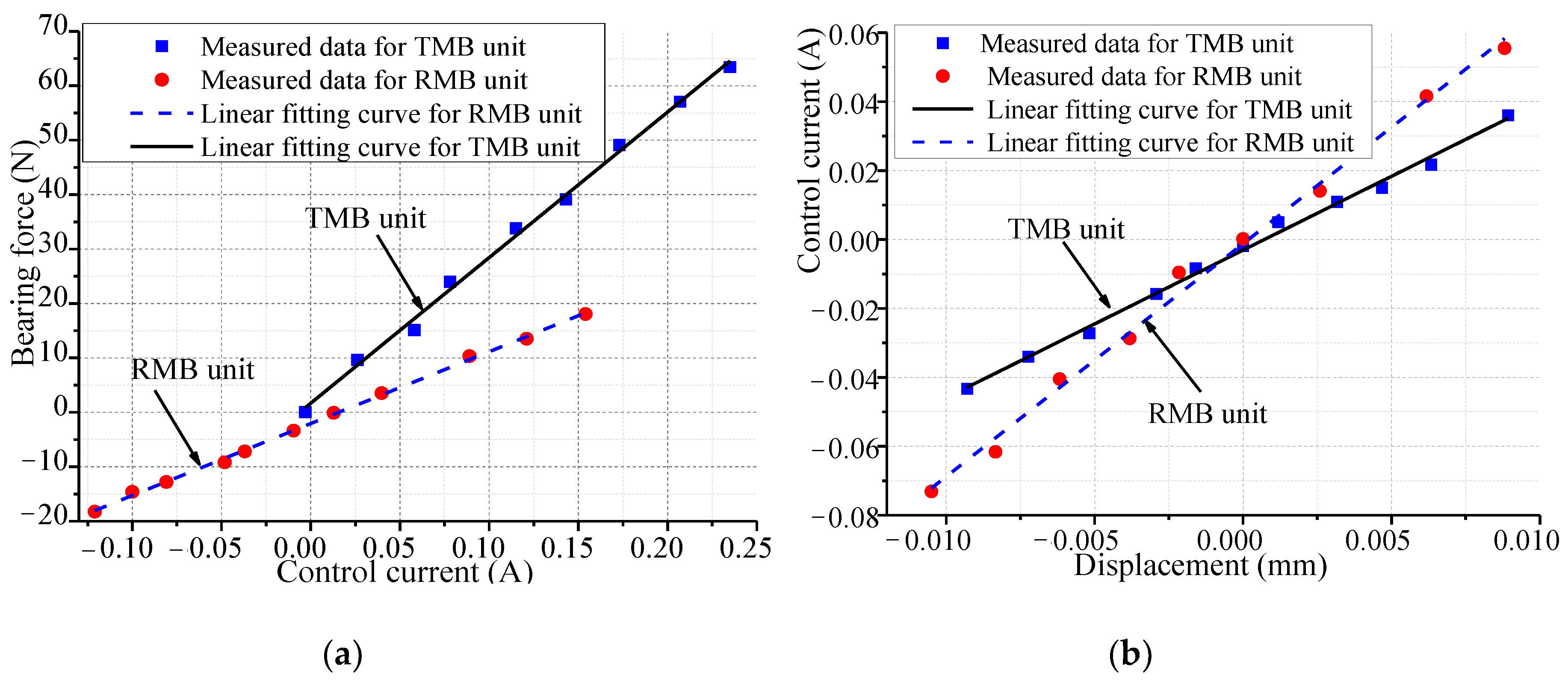
Thus, based on above test method, test results of RMB and CRAMB are recorded in Figure 18 and Figure 19 respectively. In Figure 18, current stiffness measurement value of the RMB is 173.1 N/A, with error 3.9%, while, the displacement stiffness 546.5 N/mm, with error about 7.4%. As for Figure 19, current stiffness of the CRAMB’s RMB unit is 132.4 N/A, with error 3.7%, and the displacement stiffness 674.6 N/mm, with error about 2.6%, while its TMB unit’s current stiffness 243.8 N/A, with error about 7.2%, with its displacement stiffness 998.4 N/mm, with error about 8.7%.
4.3. Under-Load Experiment Based on Drag System
The under-load experiment site based on Drag system is shown as Figure 20, in which two BLDCMs in this project are set as motor and generator respectively, connected by flexible coupling. The inverter driving the motor, dragging the generator, to put the output power into the load bank. The load bank is connected by power lines to generator. Two BLDCMs are suspended by MBs via magnetic bearing controller. The input power and output power are recorded by power analyzer. The values of phase current and voltage are recorded by oscilloscope. Thus, the power relationships among motor, generator, and load bank are established. Thus, performances of maglev BLDCM system including MB-rotor system’s stability, motor’s sustainability and thermal reliability can all be validated under load condition. In practical operation, the initial drive voltage of inverter areset under 10 V during three-stages start-up process with PWM modulation method, after it is accelerated over 8500 rpm, the drive mode is converted to PAM style, for reducing harmonic content to ensure temperature rise and radial unbalanced magnetic pull are under their limitations. The drag system is loaded as current increasing gradually, step by step. Besides, maximum current is under 67 A during the load experiment.
To suppress resonance vibration at the high speed working condition, we add two closed loop in traditional control loop to suppress the same frequency current with its corresponding bearing force.
During the whole load process, the input and output power of this drag system are displayed and recorded by power analyzers for motor and generator respectively. Current and voltage data are recorded by oscilloscopes. This drag system is loading to 33 kW with 55,332 rpm angular speed. The peak-peak value of the 3-phase control current is 190 A. The mass of the BLDCM is 41 kg, and the power density is 1.21 kW/kg. All data results during acceleration under load have been recorded and arranged as the following diagram (Table 11).
Based on drag speed-up testing data showing in Table 11, varieties of loss can be separated based on drag system. Via energy relationships among motor, generator, and load box, combined with speed-up and deceleration test, when the motor runs at 55,332 rpm, varieties of power losses can be obtained, as Table 12 shows.
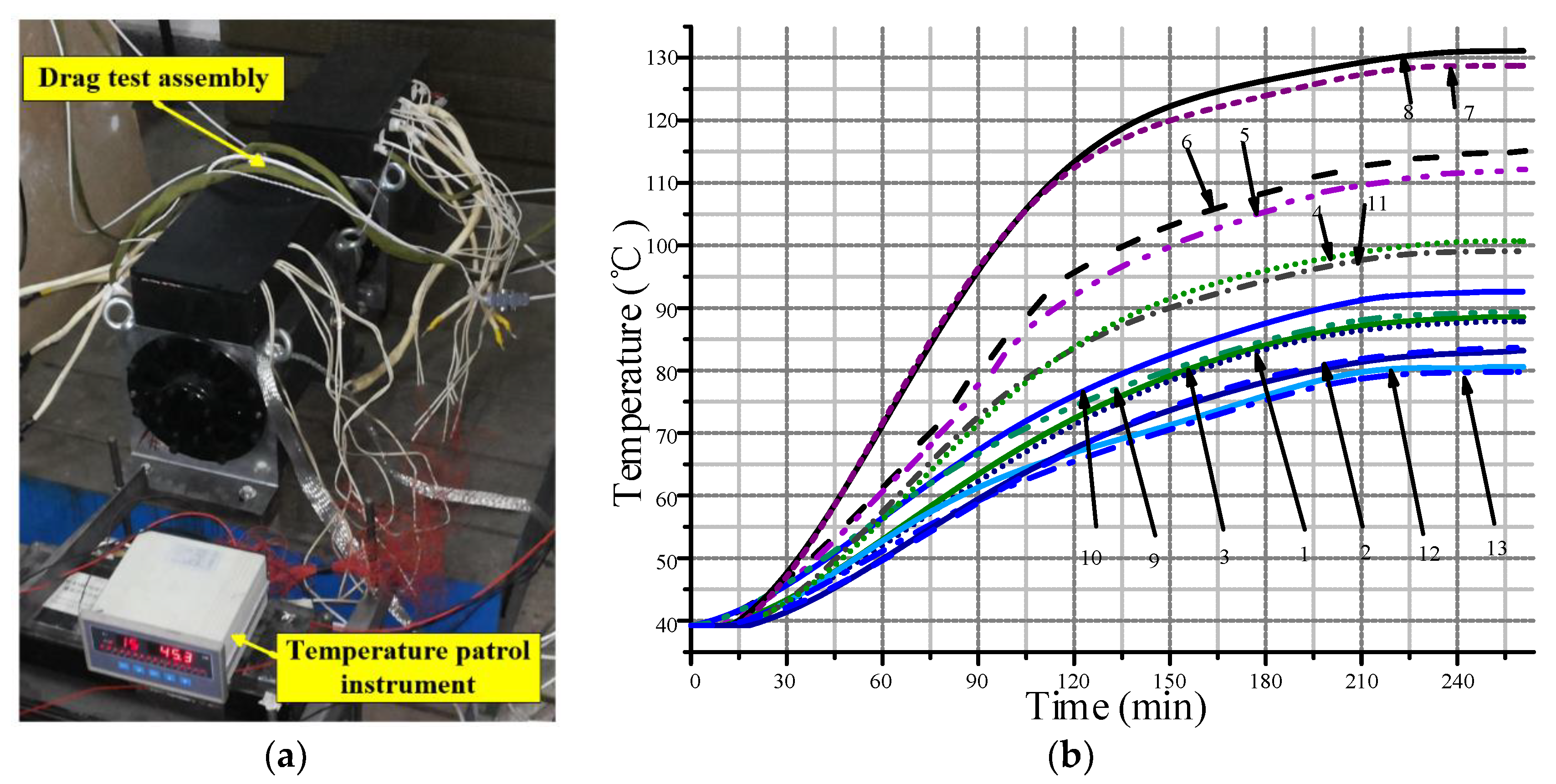
The temperature measured by those thermocouple PT100, embedded as Figure 21 shows. The highest temperature rise in motor is iron core, the next is the inner surface face to the rotor surface. For to verify the calculated temperature rise in maglev BLDCM system, 13 thermocouples are placed in the stator parts of the high-speed BLDCM, as shown in Figure 21. The temperature test environment is shown in Figure 22a, which are based on the drag load experiment. The thermocouple is connected to temperature patrol instrument, which upload test values to the upper monitor in real time. The measured temperature rise is shown in Figure 22b. The maximum temperature of HSPMSM exists in coils with F-level insulation, and stators, reaching 131 °C and 128 °C respectively. After adding water cooling, the temperature can decrease more than 19 °C at least. Except rotor, in stator parts of the BLDCM, the key temperature is located in tooth front (air gap), the value is 114 °C, as shown in position PTC 5 and 6 (Figure 21). Because we can’t place the temperature sensor on the rotor surface, so this approximate substitution method has been adopted, which has been validated by non-contact measurement via indirectly infrared thermal probe.
The error between the predicted maximum temperature and the measured one in stator parts is 9.3%. The minimum temperature rise curves are the stator coils of the RMB and the CRAMB (PTC 12 and 13 in Figure 21). Figure 22b shows the temperature rise curve of this maglev BLDCM system. The maximum temperature rise is under the safety condition.
5. Conclusions
In this paper, integration design procedure is put forward. The idea of dynamic variables based on design interface is proposed for coordinating contradictions among multi-domain requirements and integrating different design aspects, with an effective integrated design tool based on performance ratio curves put forward. The research is mainly on the following aspects:
- BLDCM and MBs are designed initially based on respective design model which is validated by FEM, generating design interface and dynamic variables.
- Design interfaces between electromagnetic design of BLDCM and electromagnetic designs of MB are integrated by rotor diameters for each different rotor Part.
- The paper proposes a tool for integrating those dynamic parameters to obtain the design point, this tool is based on performance ratio curves illustrated in Section 3.3 and Section 3.4. Design interfaces among electromagnetic performance, thermal requirements, and mechanical performance are integrated by means of various ratios among different performance index, such as rotor stress, total loss etc. Thus, the design point could be selected based on those ratio curves considering multi-physics effect and multi-domain performances comprehensively. They are all illustrated and shown in Figure 9 and Figure 11.
- Dynamic variables as integrated design tools are utilized to coordinate contradictions among multi-domain demands for motor. After initial design of motor and MB, the left dynamic variables are determined by mechanical and thermal analysis sequentially via design interfaces.
- The experiment, including drag test for BLDCM and stiffness test for MB, have been implemented to validate the effectiveness of the design results. And it makes the design procedure become a closed design loop. As measurement data of back-EMF coefficient 0.0678 Vs/rad, and RMB’s stiffness 173.1 N/A, have little error 0.1% and 3.9% respectively, corresponding to the calculation results obtained by analytical design model.
The method presented in this paper is practical and convenient for modeling and designing of maglev BLDCM system based on design parameter selection procedure and integration tool proposed in this paper. It also can be applied to analogous motor systems.
Author Contributions
Each of the authors contributed to the preparation of this research paper. Xu Liu proposed the integrated design idea and model, calculated the key parameters, finished main simulations, and wrote the paper. He also contributed to the experimental work. Gang Liu contributed to revision and proofreading of the manuscript substantially.
Acknowledgments
This research is supported by the Fundamental Research Funds for the Central universities. National nature science foundation of China: 61573032, 61421063, 61403015, 61773038 and the National Basic Research Program of China 2014CB744202. Besides, this work was also in part supported by the Beijing Science and Technology Program under Grant Z171100002217008, and in part by National Natural Science Foundation (NNSF) of China under Grant 61721091.
Conflicts of Interest
The authors declare no conflict of interest.
Nomenclature
| maximum value of electromagnetic torque | |
| Bδ | fundamental component of air-gap flux density |
| Dsi | inner diameter of motor |
| Lef | effective electromagnetic length of motor stator |
| Pout | rated power of the BLDCM |
| ω | angular rotation speed |
| Tm | torque of the motor |
| f | rotational frequency |
| Bg | peak value of air-gap flux density |
| Ac | current loading |
| J | stator current density |
| Ns | turns number per coil |
| B | flux density cutting across each coil |
| σr | conductivity of rotor parts for motor |
| Jz | eddy current density induced in axial direction |
| Hα | tangential component of magnetic field |
| La | effective electromagnetic length of rotor in motor part |
| Ra | outer diameter of rotor in motor part |
| α1n, α2n | angles spanned by the n-th region. |
| Ph, Pce, Pcs | hysteresis loss, eddy current loss (ECL), and stray loss respectively |
| Bkmax, Bkmin | major axis and minor axis of elliptic magnetic |
| Kh, Kc, Ke | coefficients of Ph, Pce, Pcs respectively |
| α | fitting coefficient of hysteresis loss |
| αb | half of the angle between two neighboring pole |
| A | effective cross area of each pole of RMB stator |
| i0 | bias current of RMB in coil |
| i | control current of RMB |
| x | rotor displacement |
| φ | magnetic flux though the pole of MB’s stator |
| ωr | frequency of rotor system |
| mr | mass matrix of rotor system |
| cr | damping matrix of rotor system |
| kr | stiffness matrix of rotor system |
| fb | radial force of RMB |
| ki | current stiffness of RMB |
| ks | displacement stiffness of RMB |
| бrm | total radial equivalent stress |
| бθm | total tangential equivalent stress |
| бrtm | radial component of thermal stress |
| бθtm | tangential component of thermal stress |
| бmtax | 1146 MPa, allowable limit of material GH4169 |
| бs | maximum value of total equivalent stress in rotor |
| fN | natural frequency of rotor system |
| Pr | total rotor loss |
| FB | maximum value of radial Force of magnetic bearing |
| T | temperature variable of motor in thermal equation |
| K (kx, ky, kz) | thermal conductivity, W/(m·K) |
| q | volume density summary of each heat source existing in solution domain, W/m3 |
| α | surface coefficient of heat transfer, W/(m2·K) |
| Tf | temperature of fluid around heat surface, K |
| µ0 | permeability of vacuum |
| δb | air-gap length of MB |
References
- Zhang, W.; Zhu, H. Synchronous Demodulation of Control Voltages for Stator Interturn Fault Detection in PMSM. IEEE Trans. Magn. 2013, 28, 5647–5654. [Google Scholar]
- Gerada, D.; Mebarki, A.; Brown, N.L.; Bradley, K.J.; Gerada, C. Design Aspects of High-Speed High-Power-Density Laminated-Rotor Induction Machines. IEEE Trans. Ind. Electron. 2011, 58, 4039–4047. [Google Scholar] [CrossRef]
- Wang, H.; Liu, K.; Ao, P. Magnetic Field and Specific Axial Load Capacity of Hybrid Magnetic Bearing. IEEE Trans. Magn. 2013, 49, 4911–4917. [Google Scholar] [CrossRef]
- Kluyskens, V.; Dehez, B. Dynamical Electromechanical Model for Magnetic Bearings Subject to Eddy Currents. IEEE Trans. Magn. 2013, 49, 1444–1452. [Google Scholar] [CrossRef]
- Ooshima, M.; Takeuchi, C. Magnetic Suspension Performance of a Bearingless Brushless DC Motor for Small Liquid Pumps. IEEE Trans. Ind. Appl. 2011, 47, 72–78. [Google Scholar] [CrossRef]
- Asama, J.; Amada, M.; Tanabe, N.; Miyamoto, N.; Chiba, A.; Iwasaki, S.; Takemoto, M.; Fukao, T.; Rahman, M.A. Evaluation of a Bearingless PM Motor with Wide Magnetic Gaps. IEEE Trans. Ind. Appl. 2011, 47, 72–78. [Google Scholar] [CrossRef]
- Shen, J.X.; Tseng, K.J.; Vilathgamuwa, D.M.; Chan, W.K. A novel compact PMSM with magnetic bearing for artificial heart application. IEEE Trans. Ind. Appl. 2000, 36, 1061–1068. [Google Scholar] [CrossRef]
- Silber, S.; Sloupensky, J.; Dirnberger, P.; Moravec, M.; Amrhein, W.; Reisinger, M. High-Speed Drive for Textile Rotor Spinning Applications. Trans. Ind. Appl. 2014, 61, 2990–2997. [Google Scholar] [CrossRef]
- Reichert, T.; Kolar, J.W.; Nussbaumer, T. Stator Tooth Design Study for Bearingless Exterior Rotor PMSM. IEEE Trans. Ind. Appl. 2013, 49, 1515–1522. [Google Scholar] [CrossRef]
- Gerada, D.; Mebarki, A.; Shanel, M.; Brown, N.L.; Bradley, K.J. Design considerations of high-speed induction machines for hightemperature applications. In Proceedings of the 18th International Conference on Electrical Machines, ICEM, Vilamoura, Portugal, 6–9 September 2008; pp. 1–6. [Google Scholar]
- Borisavljevic, A.; Polinder, H.; Ferreira, J.A. On the speed limits of permanent-magnet machines. IEEE Trans. Ind. Electron. 2010, 57, 220–227. [Google Scholar] [CrossRef]
- Centner, M.; Schäfer, U. Optimized Design of High-Speed Induction Motors in Respect of the Electrical Steel Grade. IEEE Trans. Ind. Electron. 2010, 57, 288–295. [Google Scholar] [CrossRef]
- Cho, H.-W.; Jang, S.-M.; Choi, S.-K. A Design Approach to Reduce Rotor Losses in High-Speed Permanent Magnet Machine for Turbo-Compressor. IEEE Trans. Magn. 2006, 42, 3521–3523. [Google Scholar] [CrossRef]
- Jang, S.-M.; Cho, H.-W.; Choi, S.-K. Design and Analysis of a High-Speed Brushless DC Motor for Centrifugal Compressor. IEEE Trans. Magn. 2007, 43, 2573–2575. [Google Scholar] [CrossRef]
- Van der Geest, M.; Polinder, H.; Ferreira, J.; Christmann, M. Power density limits and design trends of high-speed permanent magnet synchronous machines. IEEE Trans. Transp. Electrif. 2015, 1, 266–276. [Google Scholar] [CrossRef]
- Kolondzovski, Z.; Arkkio, A.; Larjola, J.; Sallinen, P. Power Limits of High-Speed Permanent-Magnet Electrical Machines for Compressor Applications. IEEE Trans. Energy Convers. 2011, 26, 73–82. [Google Scholar] [CrossRef]
- Cheng, W.; Sun, Y.; Huang, L.; Lv, Y.; Li, L. Analytical solution to magnetic field distribution of a parallel magnetised rotor with cylindrical or ring-type permanent magnet. IET Electr. Power Appl. 2015, 9, 429–437. [Google Scholar] [CrossRef]
- Park, C.H.; Kim, S.; Kim, K.-S. Vacuum chamber-free centrifuge with magnetic bearings. Rev. Sci. Instrum. 2013, 84, 095106. [Google Scholar] [CrossRef] [PubMed]
- Gerada, D.; Mebarki, A.; Brown, N.L.; Gerada, C.; Cavagnino, A.; Boglietti, A. High-Speed Electrical Machines: Technologies. IEEE Trans. Ind. Electron. 2014, 61, 2946–2959. [Google Scholar] [CrossRef]
- Noh, M.D.; Cho, S.R.; Kyung, J.-H.; Ro, S.-K.; Park, J.-K. Design and Implementation of a Fault-Tolerant Magnetic Bearing System for Turbo-Molecular Vacuum Pump. IEEE/ASME Trans. Mechatron. 2005, 10, 626–631. [Google Scholar] [CrossRef]
- Park, C.H.; Choi, S.K.; Ham, S.Y. Design and Control for Hybrid Magnetic Thrust Bearing for Turbo Refrigerant Compressor. In Proceedings of the 2011 IEEE International Conference on Automation Science and Engineering, Trieste, Italy, 24–27 August 2011; pp. 792–797. [Google Scholar]
- Lee, K.-C.; Jeong, Y.-H.; Koo, D.-H.; Joon Ahn, H. Development of a radial active magnetic bearing for high speed turbo-machinery motors. In Proceedings of the SICE-ICASE International Joint Conference 2006, Bexco, Busan, Korea, 18–21 October 2006; pp. 1543–1548. [Google Scholar]
- Zheng, S.; Han, B.; Guo, L. Composite hierarchical anti disturbance control for magnetic bearing system subject to multiple external disturbances. IEEE Trans. Ind. Electron. 2014, 61, 7004–7012. [Google Scholar] [CrossRef]
- Zheng, S.; Li, H.; Han, B.; Yang, J. Power consumption reduction for magnetic bearing systems during torque output of control moment gyros. IEEE Trans. Power Electron. 2017, 32, 5752–5759. [Google Scholar] [CrossRef]
- Fang, J.; Zheng, S.; Han, B. AMB vibration control for structural resonance of double-gimbal control moment gyro with high-speed magnetically suspended rotor. IEEE/ASME Trans. Mechatron. 2013, 18, 32–43. [Google Scholar] [CrossRef]
- Imoberdorf, P.; Zwyssig, C.; Round, S.D.; Kolar, J.W. Combined Radial-Axial Magnetic Bearing for a 1 kW, 500,000 rpm Permanent Magnet Machine. In Proceedings of the Applied Power Electronics Conference, APEC 2007, Anaheim, CA, USA, 25 February–1 March 2007; pp. 1434–1440. [Google Scholar]
- Zhu, Z.Q.; Ng, K.; Schofield, N.; Howe, D. Improved analytical modelling of rotor eddy current loss in brushless machines equipped with surface-mounted permanent magnets. IEE Proc. Electr. Power Appl. 2004, 151, 641–650. [Google Scholar] [CrossRef]
- Sortore, C.K.; Allaire, P.E.; Maslen, E.H.; Humphris, R.R.; Phil, A. Permanent magnet biased magnetic bearings design, construction and testing. In Proceedings of the 2nd International Symposium on Magnetic Bearing, Tokyo, Japan, 12–14 July 1990; pp. 175–182. [Google Scholar]
- Staton, D.; Cavagnino, A. Convection heat transfer and flow calculations suitable for electrical machines thermal models. IEEE Trans. Ind. Electron. 2008, 55, 3509–3516. [Google Scholar] [CrossRef]
- Kang, K.; Song, J.; Kang, C.; Sung, S.; Jang, G. Real-Time Detection of the Dynamic Eccentricity in Permanent-Magnet Synchronous Motors by Monitoring Speed and Back EMF Induced in an Additional Winding. IEEE Trans. Ind. Electron. 2017, 64, 7191–7200. [Google Scholar] [CrossRef]
- Jang, S.M.; Choi, J.Y.; You, D.J.; Yang, H.S. Electromagnetic analysis of high-speed machines with diametrically magnetized rotor; considering slotting effect and applied to new magnetization modeling. In Proceedings of the 2005 IEEE International Conference on Electric Machines and Drives, San Antonio, TX, USA, 15–18 May 2015; pp. 1204–1211. [Google Scholar]
- Zhu, J.G.; Ramsden, V.S. Improved formulations for rotational core losses in rotating electrical machines. IEEE Trans. Magn. 1998, 34, 2234–2242. [Google Scholar]
Figure 1.
The structure of the 30 kW MLBLDCM.

Figure 2.
Contradiction and integration in design procedure of maglev BLDCM.

Figure 3.
Integrated design procedure for maglev BLDCM system.

Figure 4.
Design variables of the maglev BLDCM system: (a) Design variables of BLDCM; (b) Design variables of RMB; (c) Design variables of CRAMB.
Figure 4.
Design variables of the maglev BLDCM system: (a) Design variables of BLDCM; (b) Design variables of RMB; (c) Design variables of CRAMB.

Figure 5.
Flux disc in standard parts of stator.

Figure 6.
Section view showing configuration sketch and flux paths of RMB.

Figure 7.
Configuration of the CRAMB with its flux paths.

Figure 8.
Configuration of maglev high speed rotor for maglev BLDCM.

Figure 9.
Selection about mechanical dynamic and rotor loss, and MBs etc.

Figure 10.
The rotor’s first-order bending mode, the equivalent effective stress contour for Sleeve and rotor core lamination of the RMB: (a) Analysis results of bending vibration mode for rotor assembly by FEM; (b) Analysis results of stress for sleeve by FEM; (c) Analysis results of stress for rotor core lamination of the RMB by FEM.


Figure 11.
Selection about electromagnetic and thermal performance etc.

Figure 12.
The predicted temperature rise and measured temperature rise of the high speed BLDCM with temperature distribution in stator, PM, and sleeve.
Figure 12.
The predicted temperature rise and measured temperature rise of the high speed BLDCM with temperature distribution in stator, PM, and sleeve.

Figure 13.
Thermal and stress distribution of rotor obtained by thermos-structural coupling finite element analysis: (a) thermal distribution of rotor; (b) stress distribution of rotor.
Figure 13.
Thermal and stress distribution of rotor obtained by thermos-structural coupling finite element analysis: (a) thermal distribution of rotor; (b) stress distribution of rotor.


Figure 14.
Key parts and assemblies for maglev BLDCM.

Figure 15.
Control circuit sketch and related practicality.

Figure 16.
Back-EMF waveform of the BLDCM when it decelerates from 60,000 rpm (measurement data from three phases: 291.9 V max, computational prediction: 294.2 V max).
Figure 16.
Back-EMF waveform of the BLDCM when it decelerates from 60,000 rpm (measurement data from three phases: 291.9 V max, computational prediction: 294.2 V max).

Figure 17.
Experimental platform and description for MB’s Stiffness test.

Figure 18.
Measured bearing force data versus current and displacement and measured control current versus displacement for RMB for getting stiffness: (a) bearing force versus control current; (b) Measured control current versus displacement.
Figure 18.
Measured bearing force data versus current and displacement and measured control current versus displacement for RMB for getting stiffness: (a) bearing force versus control current; (b) Measured control current versus displacement.

Figure 19.
Measured bearing force data versus current and displacement and measured control current versus displacement for CRAMB for getting stiffness: (a) bearing force versus control current; (b) Measured control current versus displacement.
Figure 19.
Measured bearing force data versus current and displacement and measured control current versus displacement for CRAMB for getting stiffness: (a) bearing force versus control current; (b) Measured control current versus displacement.

Figure 20.
The site of under-load experiment based on Drag system.
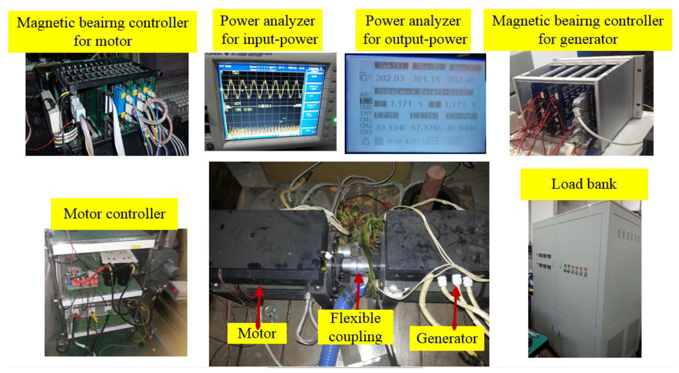
Figure 21.
Probe position of thermal resistors in MLBLDCM system.
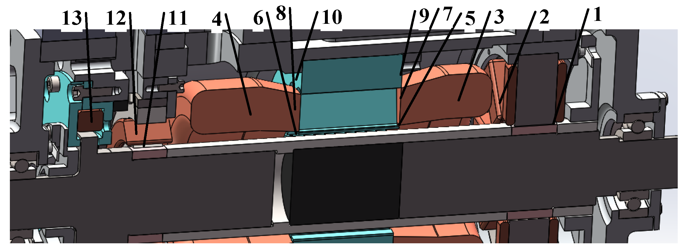
Figure 22.
Temperature rise experiment and testing curves the MLBLDCM system: (a) test bench for temperature rise experiment; (b) temperature rise curves.
Figure 22.
Temperature rise experiment and testing curves the MLBLDCM system: (a) test bench for temperature rise experiment; (b) temperature rise curves.


Table 1.
Initial design parameters consisting of key sizes for BLDCM.
| Motor Parameters | Variables | Design Value |
|---|---|---|
| Outer diameter of stator (mm) | x1 | 178 |
| Inner diameter of stator (mm) | x2 | 67.6 |
| Stator length (mm) | x3 | 60 |
| Outer diameter of rotor (mm) | x4 | (Dynamic variable) |
| Outer diameter of PM (mm) | x5 | (Dynamic variable) |
| Thickness of PM (mm) | x6 | (Dynamic variable) |
Table 2.
Core loss average coefficients.
| Material (Craftwork) | Core Loss Average Coefficients | |||||
|---|---|---|---|---|---|---|
| High Frequency (3–5 kHz) | Low Frequency (0.2–1 kHz) | |||||
| Kh | Kc | Ke | Kh | Kc | Ke | |
| 20WTG 0.2 mm (stamping, annealing) | 464.9 | 0.12 | 0.92 | 216.7 | 0.47 | 0.79 |
| 20WTG 0.35 mm (stamping, annealing) | 405.4 | 0.27 | 0.19 | 163.9 | 0.64 | 0.29 |
Table 3.
ECL and core loss of motor.
| Loss | 48,000 rpm (No-Load) | 60,000 rpm (No-Load) | 48,000 rpm (Under-Load) | 60,000 rpm (Under-Load) |
|---|---|---|---|---|
| ECL (W) | 27 | 38 | 289 | 389 |
| Core loss (W) | 15 | 26 | 187 | 317 |
Table 4.
Design parameters of slot for BLDCM.
| Slot Parameters | Variables | Design Value |
|---|---|---|
| Slot notch height Hs0 (mm) | x6 | 0.5 |
| Slot shoulder height Hs1 (mm) | x7 | 0.6 |
| Slot body height Hs2 (mm) | x8 | 24 |
| Slot notch width Bs0 (mm) | x9 | (Dynamic variable) |
| Slot upper width Bs1 (mm) | x10 | 5.6 |
| Slot bottom width Bs2 (mm) | x11 | 11.34 |
Table 5.
Design parameters for RMB.
| Parameters | Description | Design Value |
|---|---|---|
| d9 | inner radius of the stator yoke (mm) | 129 |
| d12 | Inner radius of the RMB rotor (mm) | 38 |
| d10 | Outer radius of the pole shoe (mm) | 86 |
| d11 | Inner radius of the pole shoe (mm) | X4 + δb |
| d8 | Outer radius of the RMB stator (mm) | 140.5 |
| l8 | Width of the tooth of stator core (mm) | 7.5 |
| l9 | Width of the pole shoe (mm) | 9 |
| l10 | Thickness of the stator (mm) | 23 |
| B0 | Bias flux density in air gap (T) | 0.65 |
| B1 | Control flux density in air gap (T) | 0.52 |
Table 6.
Parameters and design variables of the CRAMB.
| Parameters | Description | Values |
|---|---|---|
| d1 | Outer diameter of stator (mm) | 116 |
| d2 | Inner diameter of magnetic conducting ring (mm) | 106 |
| d3 | Inner diameter of yoke (mm) | 104 |
| d4 | Inner diameter of stator (mm) | x4 + δb |
| d5 | Outer diameter of axial window (mm) | 112 |
| d6 | Outer diameter of thrust disk (mm) | 75 |
| d7 | Inner diameter of axial window (mm) | 65 |
| l1 | The axial length of radial stator (mm) | 16.5 |
| l2 | Length of magnetic guide ring (mm) | 5 |
| l3 | The PM length in its magnetized direction (mm) | 8 |
| l4 | The axial length of side plate of axial stator (mm) | 3.8 |
| l5 | The axial length of axial window (mm) | 13.2 |
| l6 | Axial length of inner side gap of axial stator (mm) | 2.1 |
| l7 | The width of radial magnetic pole (mm) | 32 |
Table 7.
Material and stress of rotor parts.
| Motor Part | Screw-Ring | Shaft | Protect Sleeve | Shaft Stud | PM | Rotor Core |
|---|---|---|---|---|---|---|
| material | 40CrNiMo | 1Cr18Ni9Ti | GH4169 | 40CrNiMo | Sm2Co17 | 20WTG1500 |
| Maximum stress (Mpa) | 270 | 0.56 | 663 | 259 | 21.8 | 217 |
Table 8.
Heat generation rate of BLDCM and AMBs.
| Motor Part | Motor Stator | Motor Winding | Protect Sleeve | PM | MB (Rotor End) | MB (Anoth-er End) |
|---|---|---|---|---|---|---|
| Power loss (W) | 317 | 450 | 546 | 41 | 132.5 | 124.8 |
| Heat generation rate (mW/(mm3)) | 5.16 | 0.56 | 3.41 | 0.35 | 6.75 | 8.36 |
Table 9.
Final values of dynamic optimal variables.
| Key Parameters | Variables | Design Values |
|---|---|---|
| Outer diameter of rotor (mm) | x4 | 56 |
| Outer diameter of PM (mm) | x5 | 46 |
| Thickness of PM (mm) | x6 | 23 |
| Slot notch width Bs0 (mm) | x9 | 1.86 |
Table 10.
Key parameters of BLDCM.
| Design Parameter (Unit) | Value |
|---|---|
| Outer diameter of stator (mm) | 150 |
| Inner diameter of stator (mm) | 62 |
| Stator length (mm) | 60 |
| Rated speed (rpm) | 48,000 |
| Highest speed (rpm) | 60,000 |
| Rated power (kW) | 30 |
| Sleeve thickness (mm) | 6 |
| Rated voltage (V) | 380 |
| PM radius (mm) | 22.5 |
| Rated current (A) | 60 |
| turns × parallel conductors per slot | 12 × 8 |
Table 11.
Test data of drag system under load condition.
| Speed (rpm) | Input Power of the Motor (kW) | Phase Voltage of Motor (V) | Phase Current of Motor (A) | Phase Voltage of Generator (V) | Phase Current of Generator (A) | Output Power of Generator (kW) |
|---|---|---|---|---|---|---|
| 20,000 | 3.58 | 71.85 | 14.26 | 70.2 | 12.16 | 0.849 |
| 30,000 | 7.91 | 106.1 | 20.34 | 100.26 | 17.31 | 1.734 |
| 40,000 | 16.54 | 142.1 | 28.36 | 130.65 | 24.74 | 11.926 |
| 48,000 | 24.73 | 171.26 | 40.62 | 153.19 | 36.62 | 19.996 |
| 50,000 | 26.07 | 159.85 | 52 | 128 | 48 | 24.91 |
| 52,500 | 29.8 | 179.8 | 62 | 155.6 | 54 | 27.54 |
| 55,000 | 33.2 | 196.8 | 69 | 180.3 | 61 | 31.55 |
Table 12.
Varieties of power losses via experimental separation.
| Loss Style | Winding Loss | Stator Core Loss | Eddy Current Loss | Windage Loss | Total Loss |
|---|---|---|---|---|---|
| Power loss (W) | 93 | 278 | 410 | 865 | 1646 |
© 2018 by the authors. Licensee MDPI, Basel, Switzerland. This article is an open access article distributed under the terms and conditions of the Creative Commons Attribution (CC BY) license (http://creativecommons.org/licenses/by/4.0/).
Share and Cite
MDPI and ACS Style
Liu, G.; Liu, X. Integrated Design of a High Speed Magnetic Levitated Brushless Direct Current Motor System. Energies 2018, 11, 1236. https://doi.org/10.3390/en11051236
AMA Style
Liu G, Liu X. Integrated Design of a High Speed Magnetic Levitated Brushless Direct Current Motor System. Energies. 2018; 11(5):1236. https://doi.org/10.3390/en11051236
Chicago/Turabian StyleLiu, Gang, and Xu Liu. 2018. "Integrated Design of a High Speed Magnetic Levitated Brushless Direct Current Motor System" Energies 11, no. 5: 1236. https://doi.org/10.3390/en11051236
Note that from the first issue of 2016, this journal uses article numbers instead of page numbers. See further details here.