Article

Experimental Investigation into the Effect of Oil Injection on the Performance of a Variable Speed Twin-Screw Compressor

1
School of Energy and Power Engineering, Xi’an Jiaotong University, Xi’an 710049, China
2
School of Energy and Power Engineering, Zhengzhou University of Light Industry, Zhengzhou 450000, China
3
School of Engineering & ICT, University of Tasmania, Private Bag 65, Hobart TAS 7001, Australia
*
Author to whom correspondence should be addressed.
Energies 2018, 11(6), 1342; https://doi.org/10.3390/en11061342
Submission received: 1 April 2018 / Revised: 21 May 2018 / Accepted: 24 May 2018 / Published: 25 May 2018
(This article belongs to the Section I: Energy Fundamentals and Conversion)

Abstract

:
In this paper, the effect of oil injection flow rate on the performance of a variable speed twin-screw compressor was investigated experimentally. Comprehensive experiments were conducted at different compressor rotational speeds and oil injection flow rates. As the rotational speed increased from 1000 to 3000 rpm, the compressor volumetric and adiabatic efficiencies increased while the specific power consumption decreased. However, the oil injection flow rate showed different influences on the compressor performance. As the oil injection flow rate increased from 27 to 50 L/min, the adiabatic and volumetric efficiencies increased while the compressor discharge temperature and specific power decreased. Further increases in the oil injection flow rate had little effect on compressor performance at flow rates above 50 L/min. The analysis indicated that the oil injection flow rate was limited by the discharge temperature at low compressor rotational speeds and was a trade-off among two efficiencies and specific power consumption at high rotational speeds.

1. Introduction

The twin-screw compressor has been widely used in air compression processes due to its many advantages, such as its compact structure, stable operation, and high efficiency. Oil injection is important in twin-screw compressors for lubricating bearings, sealing the gas leakage paths, and cooling the air in order to lower the air discharge temperature. This is an essential technology to improve the working process of the twin-screw air compressor. Consequently, it has attracted wide attention in scientific communities.
In order to better understand the compression characteristics of the oil-injected twin-screw compressor, many researchers have developed different mathematical models to evaluate compressor performance. Fleming and Tang [1] constructed a mathematical model to determine the aggregate leakage through six separate types of leakage paths. Fleming et al. [1] further improved the mathematical model to investigate the working process of a twin-screw compressor by incorporating geometric features and operating conditions. Specifically, the effect of oil injection on compressor performance was studied under different operating conditions. Hanjalic and Stošić [2] incorporated the conservation of mass and energy, fluid leakage, oil or other fluid injection, and heat transfer into a mathematical model. This model was used to simulate the thermodynamic and fluid flow process in twin-screw compressors and expanders. Peng et al. [3] studied the thermodynamic working process of an oil-flooded air screw compressor by using experimentally-obtained pressure–Volume (p-V) diagrams. The effects of pressure ratio, oil-to-gas mass ratio, and compressor rotational speed on the compression process were investigated. Stošić et al. [4,5] proposed a suitable program to optimize the twin-screw compressor shape, dimensions, and operating parameters. Wu et al. [6,7] proposed a mathematical model to investigate the thermodynamic working process inside the twin-screw compressor using p-V diagrams. An optimal super-feed pressure was proposed according to the isentropic efficiency, which was calculated using the measured p-V diagram. Chen et al. [8] used the p-V indicator diagram to evaluate the thermodynamic compression process of a twin-screw compressor with a slide valve assembly under part-load conditions. He et al. [9] performed a thermal and hydraulic analysis on the flow around the motor in semi-hermetic twin-screw refrigeration compressors.
Some researchers further investigated the effect of oil injection on the performance of twin-screw compressors. Stošić et al. [5] investigated the effect of oil injection on the working process of a twin-screw compressor using a numerical model. The oil temperature and injection position had a significant effect on compressor performance, while the air/oil mass ratio and oil viscosity had a negligible effect. Fujiwara and Osada [10] used a heat transfer model to evaluate the influence of oil injection on actual compressor geometries. Results showed that oil droplets had a very small residence time. This indicated that the heat transfer between the oil and air was most often because of the oil film lying on the compressor volume wall. De Paepe et al. [11] addressed the effect of oil atomization on the working process of an oil-injected twin-screw compressor. Results showed that oil atomization considerably increased heat transfer; however, it did not significantly affect the compressor performance. The compressor performance increased as the oil temperature was reduced, while an increase in the oil flow rate produced only small gains. Seshaiah et al. [12,13] studied the performance of an oil-injected twin-screw compressor, noting the compression of air, argon, and helium. The oil inlet temperature had greater effects than the oil flow rate. Hsieh et al. [14] calculated temperature distributions in the rotors of an oil-injected air screw compressor. The heat transfer between bearings and rotors, and between the air and screw, were discussed and analyzed. Recently, Wu et al. [15] investigated the effect of lubricating oil on the performance of a semi-hermetic twin-screw refrigeration compressor as the oil was applied to suction and discharge end bearings, and then returned to the suction pipe. The results showed that compressor performance increased as the oil flow rate was reduced in the suction pipe and suction end bearings. As the oil injection location was moved from the suction pipe to a proper compression chamber position, the oil flow rate and compressor performance increased.
The above literature review shows that oil-injected twin-screw compressors have been widely investigated in the past few decades. However, very few investigations report on the performance of variable-speed twin-screw compressors. Cuevas et al. [16] investigated the frequency control of a scroll compressor. The results showed that compressor frequency did not significantly affect compressor efficiency. The compressor efficiency was mainly dependent on the compressor pressure ratio. Liang et al. [17,18,19,20,21,22] investigated the application of frequency conversion technology in air compressor control systems and discussed the advantages and disadvantages of these technologies in compressor applications. The study [23,24,25,26,27,28] demonstrated the significance of employing frequency conversion technology in the compressor industry.
In this paper, an experimental test system was developed to investigate the effect of oil injection on the variable-speed twin-screw compressor. Compressor performance was studied under different compressor rotational speeds and different oil flow rates. The discharge temperature, volumetric and adiabatic efficiencies, and specific power consumption were used to evaluate the performance of the variable-speed compressor. This study provides a guideline for engineers and researchers to determine oil flow rates in variable-speed twin-screw air compressors.

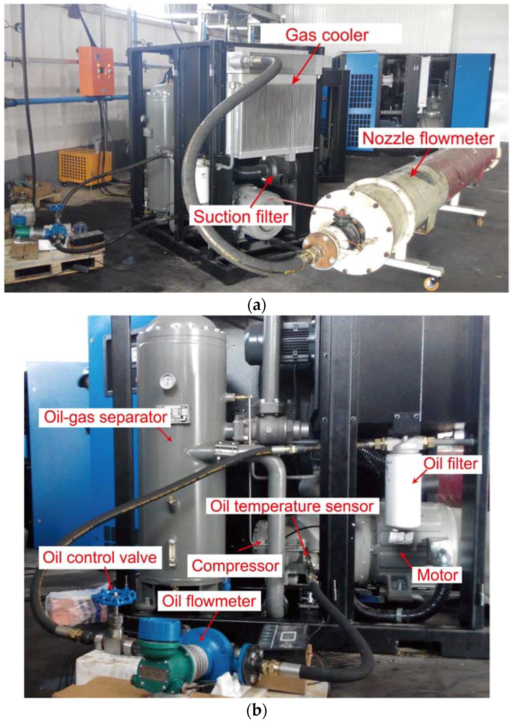
2. Experimental Setup

2.1. Compressor Test System

The schematic drawing of a variable-speed-driven twin-screw air compressor test system is shown in Figure 1. It consists of a TRL135 twin-screw air compressor with frequency control, oil/air separator, oil cooler, air cooler, air suction filter, oil filter, oil control valve, oil and air flow meters, and a lot of piping and valves. The TRL135 twin-screw air compressor was equipped with an inverter controller and permanent magnet motor. Detailed information about this twin-screw air compressor is listed in Table 1. The system includes two loops: an air open loop and an oil loop. In the air loop, fresh air is sucked in by the compressor and mixed with oil that has been injected into the compression chamber from the oil circulation loop. Then, the air/oil mixture is compressed and discharged at a back pressure of 0.8 MPa. The compressed air/oil mixture is discharged into the air/oil separator, where the oil and air are separated. The air flows into an air-cooler, where it is cooled and then discharged into the environment via an air flow meter. The air flow is measured using the ASME nozzle method. The pressure difference in the nozzle is measured using differential pressure sensors with a reading accuracy of 0.3%. The air flow is then calculated according to the differential pressure, temperature, and diameter of the nozzle in the Kingview data collection system (V6.5, Wellintech, Beijing, China). In the oil circulation loop, the separated oil is pumped from the air/oil separator and cooled in the oil cooler. Then, the oil is injected into the compressor from an oil injection port and retained at the rotor cavity with a volume ratio of 1.1. The oil is compressed and then flows back into the air/oil separator, where it is separated from the compressed air/oil mixture. Mineral oil (N46) is used in the test. The oil flow rate is controlled by an oil control valve and measured by an oil flow meter (elliptic gear mass flow meter) with a full scale of 1–6 m3/h and an accuracy of ±0.5% of full scale. Pictures of the twin-screw compressor test unit and the oil circulation loop are shown in Figure 2a,b, respectively.

2.2. Experimental Conditions and Data Reduction

In order to investigate the effect of oil injection on the variable-speed twin-screw compressor, a compressor was tested under different oil flow rates and rotational speeds. The operating conditions are listed in Table 2. Performance parameters, such as adiabatic efficiency, volumetric efficiency, specific power consumption, and discharge temperature are used to evaluate the compressor performance. These performance parameters are calculated, using the measured data, with the following equations:
Adiabatic power:
W a d = k k 1 P s Q v [ ( P d P s ) k 1 k 1 ]
Adiabatic efficiency:
η a d = W a d / W c o m p
Volumetric efficiency:
η v = Q v / Q v t h
Specific power:
w c o m p = W c o m p / Q v
where k is the specific heat ratio of air. Ps and Pd are compressor suction and discharge pressure, respectively. Qv is the actual compressor air flow rate and Qv-th is the theoretical compressor air flow rate. The actual air flow rate is measured using the ASME nozzle flow meter. The theoretical air flow rate is calculated according to the compressor theoretical displacement volume. Wad and Wcomp are the compressor adiabatic power consumption and actual power consumption, respectively. The actual compressor power is measured using a Digital Power Meter with a reading accuracy of ±0.1%. wcomp is the specific power consumption, which is determined by the measured power consumption and air flow rate. η v and η a d are compressor volumetric and adiabatic efficiency, respectively. The discharge temperature Td is measured using a Class-A RTD temperature sensor with an accuracy of ±0.15 °C.

2.3. Error Analysis

The accuracy of the sensors is listed above. The measurement uncertainty of the temperatures and pressures can be directly determined by the sensor accuracy. However, systematic measurement errors due to sensor accuracy, in relation to the air flow rate, specific power consumption, volumetric efficiency, and adiabatic efficiency have to be isolated by error propagation calculations using the Kline and McClintock method [23]. This method is expressed in the following equation:
w R = [ ( R x 1 w 1 ) 2 + ( R x 2 w 2 ) 2 + + ( R x n w n ) 2 ] 1 / 2
where wR is the resultant uncertainty, and w1, w2, …, and wn are the uncertainties in relation to the independent variables. R is a given function of the independent variables x1, x2, …, and xn. Using this equation, the uncertainties relating to the air flow rate, specific power consumption, volumetric, and adiabatic efficiencies are 3%, 3.1%, 3.5%, and 0.5%, respectively.

3. Results and Discussion

The experiment was carried out at compressor rotational speeds ranging from 1000 to 3000 rpm, which constitute the typical variable-speed range for twin-screw air compressors. The oil flow rate varied from 27 to 87 L/min. The compressor suction and discharge pressures were maintained at 0.1 and 0.8 MPa, respectively. The effects of the compressor rotational speed and oil injection flow rate on the discharge temperature, volumetric efficiency, adiabatic efficiency, and specific power consumptions are shown below.

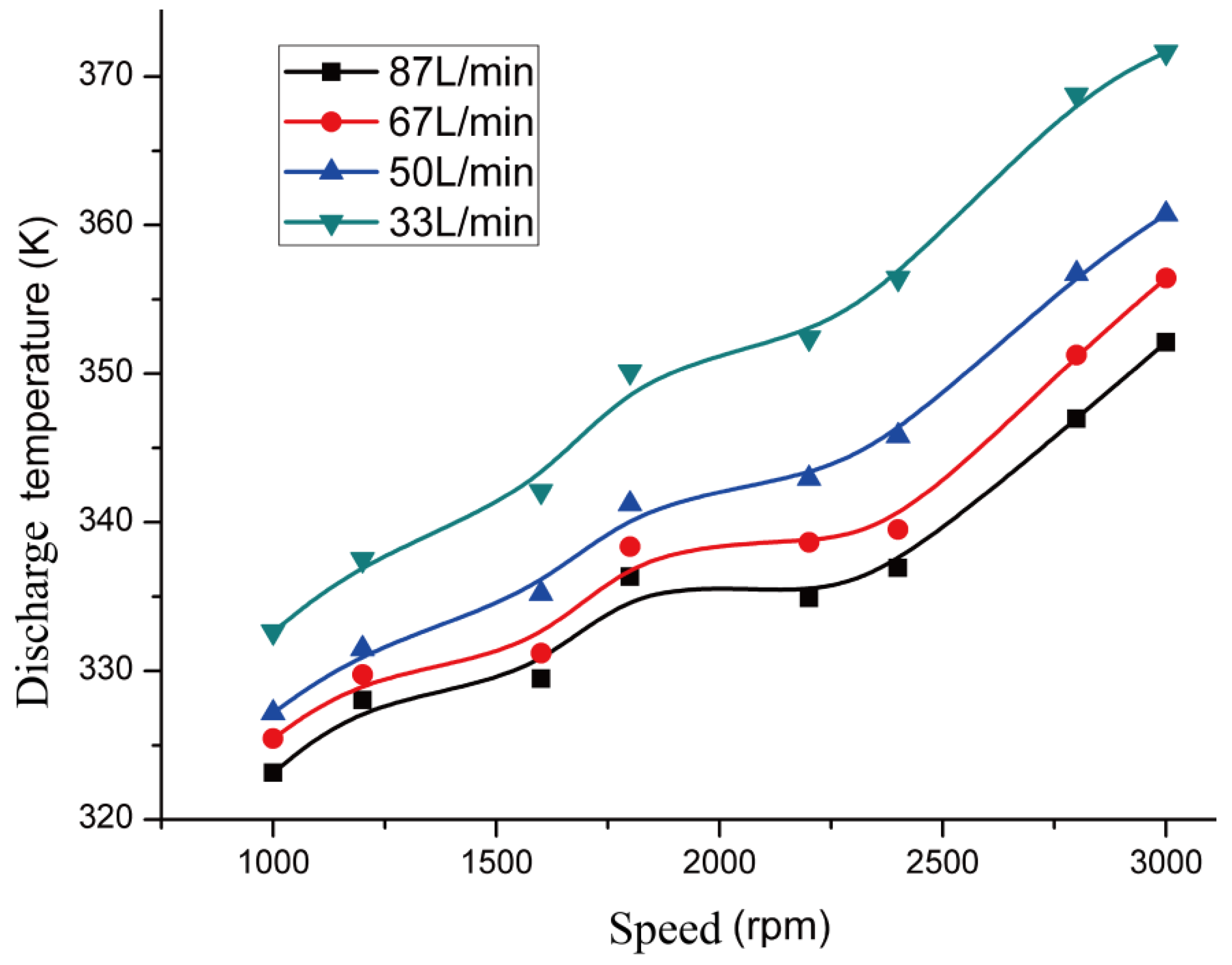
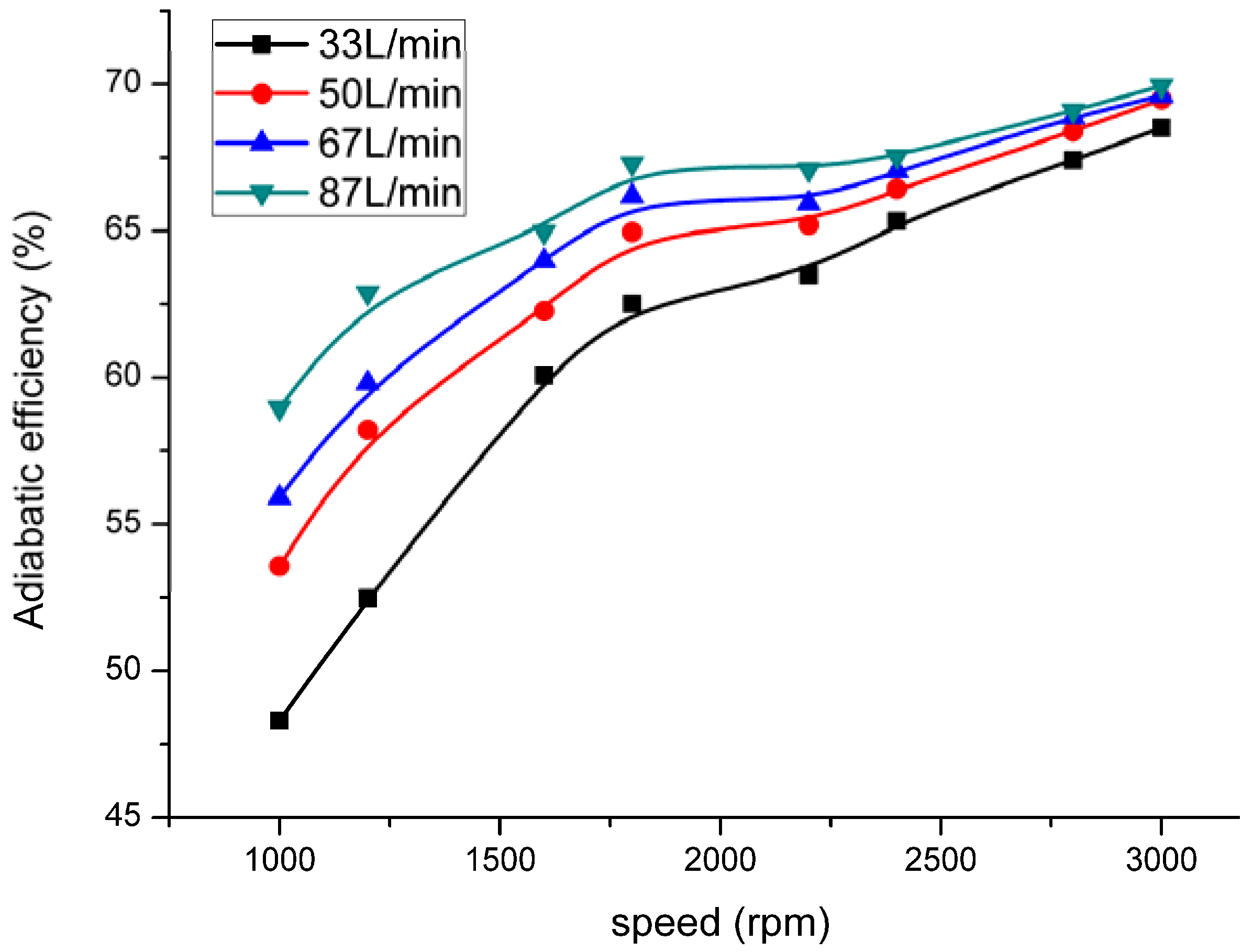
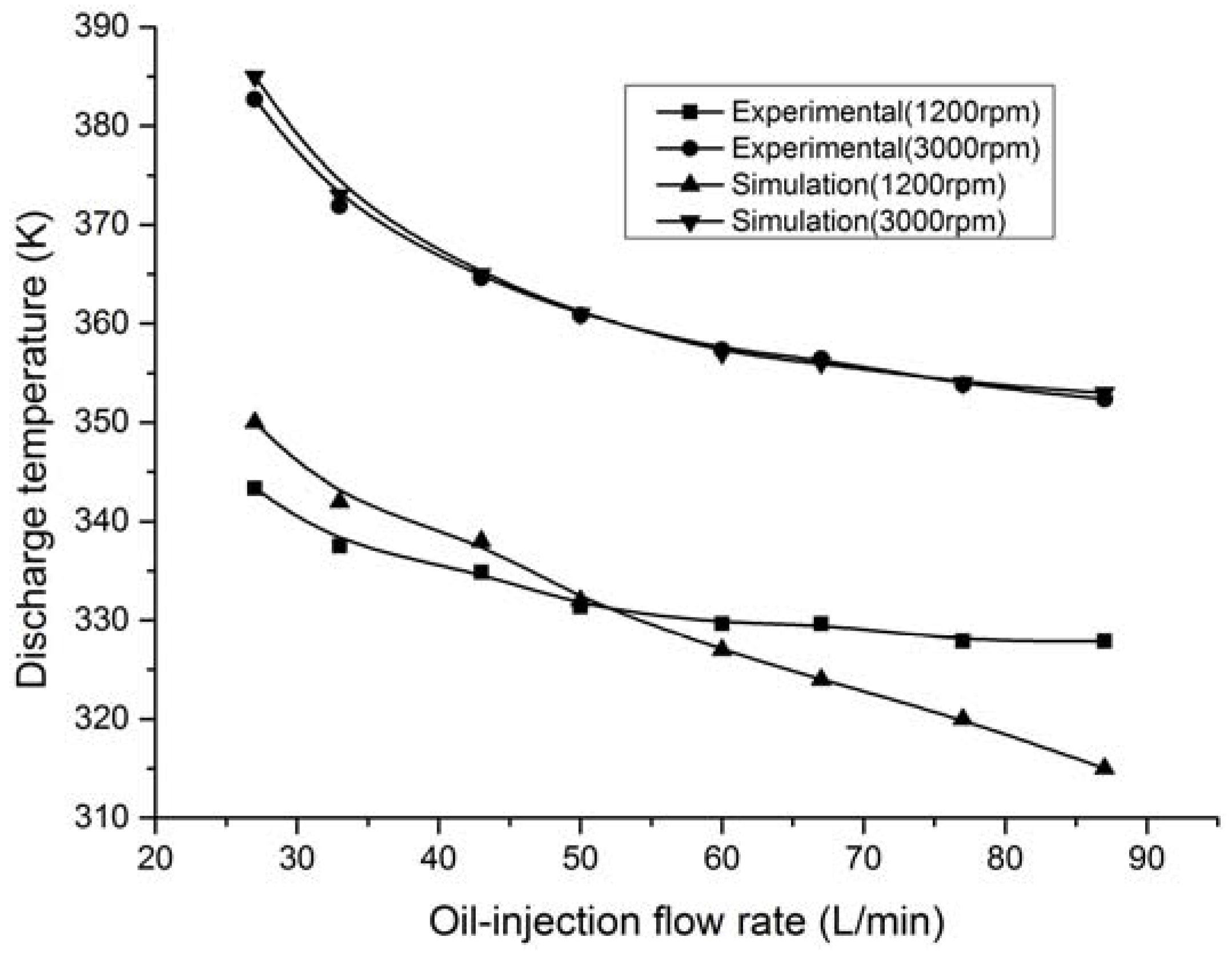
3.1. Effect of Oil Injection on Thermodynamic Performance

The variation of the compressor discharge temperature under different rotational speeds is shown in Figure 3. For all studied oil flow rates, the compressor discharge temperature increased substantially as the compressor rotational speed increased from 1000 to 3000 rpm. This was mainly due to the heat transfer time in the compression chamber. As the speed increased, the air compression time decreased, and hence the heat transfer time between the air and oil in the compression chamber decreased. Therefore, less energy was removed from the air by the oil, and hence the discharge air temperature increased.
The discharge temperature decreased continuously as the oil flow rate increased from 27 to 87 L/min, as shown in Figure 4. This was mainly due to the heat transfer between the oil and air in the compression and discharge chambers. The oil cools the air in the compression and discharge chambers, leading to a reduction in the air discharge temperature. As the oil flow rate increased, the amount of oil injected into the compression chamber increased, and hence more energy in the air was absorbed by the oil. The discharge air temperature decreased accordingly. This finding is consistent with that reported in Peng et al. [3].
Moreover, the oil flow rate could neither be too large for the low compressor rotational speed nor too small for the high compressor rotational speed, as shown in Figure 3 and Figure 4. The discharge air temperature was found to be very low at the high oil flow rate and low compressor rotational speed. This is not good for the compressor. If the discharge air temperature is too low, moisture in the compressed air condenses, which causes corrosion and other problems in the downstream process. This indicates that the oil-flow rate cannot be too high when the rotational speed is low. On the other hand, the discharge temperature is too high at the low oil flow rate when the rotational speed is high. This is also dangerous for the compressor, since the high discharge temperature affects the stability of the oil.
The variation of the compressor volumetric efficiency under different compressor rotational speeds and oil injection flow rates are shown in Figure 5 and Figure 6. As the rotational speed increased from 1000 to 3000 rpm, the volumetric efficiency increased by up to 9% at the studied oil injection flow rate. This could be explained by the working principle of the twin-screw compressor. As discussed in Fleming and Tang [1], there were six separate types of leakage paths in the twin-screw air compressor. Air leaked via these paths, between the compression and suction/discharge chambers in the compressor, which largely reduced the volumetric efficiency. The amount of leakage depended on the pressure difference between the leakage paths and the leaking times. Increasing the compressor rotational speed decreased the leaking time, which reduced the amount of air leaking through the leakage paths and, in turn, improved the volumetric efficiency. Furthermore, one of the major purposes of oil injection is to seal the leakage path. However, this is effective only if the oil can form a sealing film in the leakage path. As shown in Figure 5, the increase in the volumetric efficiency was relatively low as the rotational speed increased from 1000 to 1800 rpm. This was because the rotational speed was not high enough to form a proper oil sealing film. As the speed increased from 1800 to 2400 rpm, an oil film gradually formed and the sealing became more and more effective. Hence the volumetric efficiency increased sharply. At high speed (2400 rpm and above), the oil film was already formed. The additional increase in volumetric efficiency was mainly due to the reduction in leaking time. This explained why the volumetric efficiency increased gently at high rotational speeds.
The change in volumetric efficiency, in relation to the oil injection flow rate at different compressor rotational speeds, is shown in Figure 6. For all studied rotational speeds, the volumetric efficiency was found to increase as the oil flow rate increased from 27 to 87 L/min. However, as the oil flow rate increased beyond 50 L/min, increases in the oil flow rate no longer caused a significant increase in the volumetric efficiency. This could be explained by the oil sealing. When the oil flow rate was high enough, a sealing oil film formed, which sealed the leakage paths. At this oil flow rate, the volumetric efficiency reached its peak value. Further increases in the oil flow rate did not improve the sealing any further and hence had no significant effect on the volumetric efficiency. This indicated an optimal oil flow rate for the twin-screw compressor in terms of the volumetric efficiency.
The variation of compressor adiabatic efficiency at different rotational speeds and oil flow rates is shown in Figure 7 and Figure 8. As the compressor rotational speed increased from 1000 to 3000 rpm, the adiabatic efficiency increased by 35%, at the low oil injection flow rate (33 L/min), and by 20% at the high oil injection flow rate. In the compression chamber, the oil cools the air and, as a consequence, the compression process tends to be polytropic. As the rotational speed increased, the cooling time reduced, and hence the cooling was less effective. Therefore, the polytropic compression process approached adiabatic compression. From this point of view, the compressor adiabatic efficiency was supposed to decrease as the compressor speed increased. However, the increase in compressor speed reduced the air leakage, as evidenced by the volumetric efficiency in Figure 5. At the same time, the high rotational speed ensured the formation of an oil film between the male and female compressor rotors, and between the rotor tip and casing. The formation of this oil film substantially reduced the friction loss in the compressor and hence reduced the actual power consumption. The increase in air flow rate and reduction in friction loss were the main causes of the increase in adiabatic efficiency as the compressor rotational speed increased from 1000 to 3000 rpm.
As shown in Figure 8, the adiabatic efficiency increased for all rotational speeds as the oil flow rate increased from 27 to 87 L/min. This was mainly due to two factors: (i) The increase in oil flow rate reduced the friction loss by enhancing the lubrication between the male and female rotors, and between the rotors and casing; and (ii) the high oil flow rate provided a better sealing effect, as discussed above, and hence the air flow rate increased. However, it was also found that the effect of the oil injection flow rate on adiabatic efficiency was greater at low rotational speeds (up to 26%); at high speeds, it was either lesser, or otherwise the oil injection flow rate had no effect at all. This was because the heat transfer time in the compression chamber was shorter at high speed. The oil flow rate increased, although the air was not cooled effectively because of the short heat transfer time.
The variation in specific power consumption of the twin-screw compressor is shown in Figure 9. As the rotational speed increased from 1000 to 3000 rpm, specific power consumption decreased. This was mainly due to a reduction in leakage and the formation of an oil film at the high rotational speeds. These two effects were greater at low rotational speeds (from 1000 to 1800 rpm) and low oil injection flow rates, since the oil film was not sufficiently formed to seal the leakage paths properly and lubricate the friction surfaces. Therefore, the specific power consumption dropped sharply. The sealing oil film was gradually formed as the rotational speed increased to above 1800 rpm, leading to good sealing and lubrication. Further increasing the rotational speed did not lead to a high reduction in leakage and friction loss. Therefore, the change in specific power consumption tended to be gentle at high oil flow rates.
The oil flow rate had a larger effect on the specific power at low rotational speeds than it did at high rotational speeds, as shown in Figure 10. At high rotational speeds, an oil film was formed, but the change in the oil flow rate had less of an effect on leakage and friction losses. However, it was difficult to form an oil film at low rotational speeds. Increasing the oil flow rate would help to seal leakage paths and enhance lubrication.

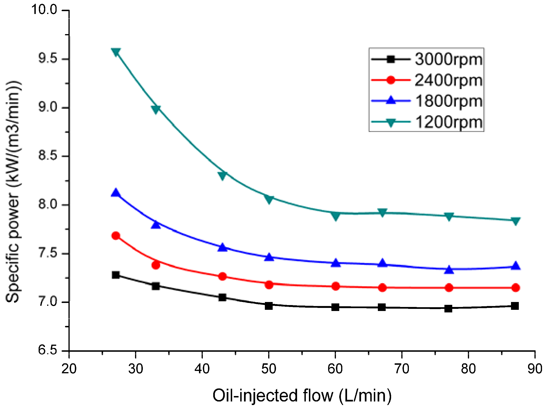
3.2. Optimization of the Oil Injection Flow Rate

As discussed in the previous section, the oil injection flow rate had a large effect on the performance of the variable-speed twin-screw air compressor. In general, the higher the oil flow rate, the better the system performance. However, once the oil flow rate had reached a certain value, further increases in the oil flow rate did not cause significant improvements in system performance. Furthermore, high oil flow rates may result in a low discharge temperature, lower than the dew point temperature at the compressor outlet, which causes condensation problems. Therefore, an optimal oil injection flow rate exists. This optimal value depended on many factors, such as rotational speed, discharge temperature, adiabatic efficiency, and volumetric efficiency. Table 3 lists the range of oil injection flow rates, based on different performance parameters, and the trade-offs among these parameters. The range of oil flow rates was selected on the basis of the following performance criteria: (i) In order to ensure the reliability and safety of the compressor operation, the discharge air temperature is maintained between 332 and 373 K, since high discharge temperature affects the lubricating oil stability and low discharge temperature causes condensation issues; (ii) for volumetric and adiabatic efficiency, the change in volumetric and adiabatic efficiency is less than 1%; and (iii) for specific power consumption, the change in specific power consumption is less than 3%. The trade-offs in oil injection flow rates ensure that the compressor operates in a reliable and efficient manner, in terms of the four performance parameters.
Table 3 shows that the key parameter affecting the oil flow rate at low rotational speeds (<1600rpm) was the discharge temperature. If the oil flow rate was too high at low rotational speeds, the air was over-cooled, causing discharge temperatures to be potentially lower than the condensation temperature at the discharge pressure. However, for high rotational speeds, the optimal oil flow rate was determined by volumetric efficiency, adiabatic efficiency, and specific power consumption. The results showed that the compressor could reach its optimal performance when the oil flow rate reached 50 L/min. Further improvements in the oil flow rate did not substantially affect the performance of the compressor. This finding is consistent with the common industry practice of using a single oil flow rate in most variable-speed air compressors.

3.3. The Heat Transfer Model in Compression Chamber

According to Table 3, the key factor for limiting the oil injection of the compressor is the compressor discharge temperature. Therefore, the heat transfer model in the compression chamber is considered.
In order to consider the effect of convection on the lubricating oil and compressed air, a single oil droplet is selected as the research object. The heat transfer coefficient between the lubricating oil and the compressed air can then be calculated.
The heat transfer correlation between the air and lubricating oil can be expressed by Equation (6) [22]:
N u = 2 + 0 . 6 R e 0.5 P r 0.33 .
The Reynolds number Re and Pr number can be determined by Equations (7) and (8), respectively:
R e = ρ l d 32 ν l μ l
P r = c p _ g μ g λ g
where ρ l is the density of oil droplets, ρ g is air density, u l is the dynamic viscosity of oil droplets, u g is the aerodynamic viscosity, c p _ g is the specific volume of air pressure, and λ g is the air thermal conductivity. The relative velocity of oil droplets and air should be calculated when the Reynolds number Re is solved.
| ν l | = ( 2 | P l P g | ) / ρ l
where Pl and Pg are the transient pressure of the oil droplet and air, respectively.
The surface heat transfer coefficient between the oil droplet and air is determined by Equation (10):
α = N u λ l d 32 .
Therefore, the heat exchange between the oil droplet and air can be obtained by Equation (11), and the total heat exchange can be calculated by Equation (12):
Q i = a i A i ( T g _ i - T l _ i )
Q z = i = 1 n Q i
where n is the number of oil drops in the compression chamber. It is assumed that the diameter of oil drops in the compression chamber is the same. The PIV test proved that the diameter of the oil droplet is generally in the 0.5~0.8 mm range. In this paper, the diameter of the oil drop was set at 0.6 mm. Based on the thermodynamic model of the screw compressor [24,25], and the heat transfer model proposed in this paper, we can predict the discharge temperature of the compressor.
As shown in Figure 11, the theoretical model can accurately predict the discharge temperature at 3000 rpm, while it is quite different from the experiment at 1200 rpm. This shows that the heat transfer of oil and compressed air is more efficient when the speed is higher. However, the experimental discharge temperature is higher than the theoretical discharge temperature, which means that at low speed, the heat transfer between oil droplets and the air is poor and cannot be predicted by the heat transfer model presented in this paper.

4. Conclusions

In this paper, the effect of oil injection flow rate on the performance of a variable-speed air compressor was investigated experimentally. Both the compressor rotational speed and oil injection flow rate had a large influence on compressor performance. As the rotational speed increased from 1000 to 3000 rpm, the discharge temperature, volumetric efficiency, and adiabatic efficiency increased substantially, while the compressor specific power consumption decreased. As the oil injection flow rate increased from 27 to 87 L/min, the air compressor performance increased until the oil flow rate reached 50 L/min. Further increases in oil injection flow rate did not cause any significant change in compressor performance. By considering the typical compressor performance parameters, including discharge temperature, volumetric efficiency, adiabatic efficiency, and specific power consumption, it was found that the optimal oil injection rate was around 50 L/min. This optimal oil flow rate was suitable for all compressor rotational speeds except very low speeds. This result provides a theoretical basis for the application in common practice of constant oil injection flow rates in the variable-speed air-compressor.

Author Contributions

Z.H. and T.W. conceived and designed the experiments; T.W. performed the experiments; Z.H., X.P. and Z.X. analyzed the data; X.W. contributed analysis tools; T.W. wrote the paper.

Acknowledgments

Thanks to the hard work of the co-authors.

Conflicts of Interest

There is no conflict of interest.

References

  1. Fleming, J.S.; Tang, Y.; Cook, G. The twin helical screw compressor, part 2: A mathematical model of the working process. Proc. Inst. Mech. Eng. Part C J. Mech. Eng. Sci. 1998, 212, 369–380. [Google Scholar] [CrossRef]
  2. Hanjalic, K.; Stošić, N. Development and optimization of screw machines with a simulation model-Part II: Thermodynamic performance simulation and design optimization. Trans. ASME J. Fluids Eng. 1997, 119, 664–670. [Google Scholar] [CrossRef]
  3. Peng, X.; Xing, Z.; Cui, T.; Li, L. Analysis of the working process in an oil-flooded screw compressor by means of an indicator diagram. Proc. Inst. Mech. Eng. Part A J. Power Energy 2002, 216, 465–470. [Google Scholar] [CrossRef]
  4. Stošic, N.; Milutinović, L.; Hanjalić, K.; Kovačević, A. Investigation of the influence of oil injection upon the compressor working process. Int. J. Refrig. 1992, 15, 206–220. [Google Scholar] [CrossRef]
  5. Stošić, N.; Smith, I.K.; Kovačević, A. Optimization of screw compressors. Appl. Therm. Eng. 2003, 23, 1177–1195. [Google Scholar] [CrossRef]
  6. Wu, H.; Li, J.; Xing, Z. Theoretical and experimental research on the working process of screw refrigeration compressor under superfeed condition. Int. J. Refrig. 2017, 30, 1329–1335. [Google Scholar] [CrossRef]
  7. Wu, H.; Xing, Z.; Shu, P. Theoretical and experimental study on indicator diagram of twin-screw refrigeration compressor. Int. J. Refrig. 2004, 27, 331–338. [Google Scholar]
  8. Chen, W.; Xing, Z.; Tang, H.; Wu, H. Theoretical and experimental investigation on the performance of screw refrigeration compressor under part-load conditions. Int. J. Refrig. 2011, 34, 1141–1150. [Google Scholar] [CrossRef]
  9. He, Z.; Xing, Z.; Chen, W.; Wang, X. Thermal and hydraulic analysis on the flow around the motor in semi-hermetic twin-screw refrigeration compressors. Appl. Therm. Eng. 2013, 58, 114–124. [Google Scholar] [CrossRef]
  10. Fujiwara, M.; Osada, Y. Performance analysis of an oil-injected screw compressor and its application. Int. J. Refrig. 1995, 18, 220–227. [Google Scholar] [CrossRef]
  11. Paepe, M.D.; Bogaert, W.; Mertens, D. Cooling of oil injected screw compressors by oil atomization. Appl. Therm. Eng. 2005, 25, 2764–2779. [Google Scholar] [CrossRef]
  12. Seshaiah, N.; Ghosh, S.K.; Sahoo, R.K.; Sarangi, S.K. Mathematical modeling of the work cycle of oil injected rotary twin screw compressor. Appl. Therm. Eng. 2007, 27, 145–155. [Google Scholar] [CrossRef]
  13. Seshaiah, N.; Sahoo, R.K.; Sarrangi, S.K. Theoretical and experimental studies on oil injected twin-screw air compressor when compressing different light and heavy gases. Appl. Therm. Eng. 2010, 30, 327–339. [Google Scholar] [CrossRef]
  14. Hsieh, S.H.; Shih, Y.C.; Hsieh, W.H.; Lin, F.Y.; Tsai, M.J. Calculation of temperature distributions in the rotors of oil-injected screw compressors. Int. J. Therm. Sci. 2011, 50, 1271–1284. [Google Scholar] [CrossRef]
  15. Wu, X.; Xing, Z.; He, Z.; Wang, X.; Chen, W. Effects of lubricating oil on the performance of a semi-hermetic twin-screw compressor. Appl. Therm. Eng. 2017, 112, 340–351. [Google Scholar] [CrossRef]
  16. Cuevas, C.; Lebrun, J. Testing and modeling of a variable speed scroll compressor. Appl. Therm. Eng. 2009, 29, 469–478. [Google Scholar] [CrossRef]
  17. Liang, H.B.; Li, X.H. Application of Frequency Conversion Technology in Air-compressor Units Control System. Procedia Eng. 2011, 15, 944–948. [Google Scholar] [CrossRef]
  18. Liu, Z.; Li, H.; Liu, K.; Yu, H.; Cheng, K. Design of high-performance water-in-glass evacuated tube solar water heaters by a high-throughput screening based on machine learning: A combined modeling and experimental study. Sol. Energy 2017, 142, 61–67. [Google Scholar] [CrossRef]
  19. Li, G.; Wu, Y.; Zhang, Y.; Zhi, R.; Wang, J.; Ma, C. Performance study on a single-screw expander for a small-scale pressure recovery system. Energies 2016, 10, 6. [Google Scholar] [CrossRef]
  20. Liu, Z.; Wu, D.; Yu, H.; Ma, W.; Gin, G. Field measurement and numerical simulation of combined solar heating operation modes for domestic buildings based on the Qinghai-Tibetan plateau case. Energy Build. 2018, 167, 312–321. [Google Scholar] [CrossRef]
  21. Liu, Z.; Xu, W.; Zhai, X.; Qian, C.; Chen, X. Feasibility and performance study of the hybrid ground-source heat pump system for one office building in Chinese heating dominated areas. Renew. Energy 2017, 101, 1131–1140. [Google Scholar] [CrossRef]
  22. Liu, Z.; Cheng, K.; Li, H.; Cao, G.; Wu, D.; Shi, Y. Exploring the potential relationship between indoor air quality and the concentration of airborne culturable fungi: A combined experimental and neural network modeling study. Environ. Sci. Pollut. Res. 2018, 25, 3510–3517. [Google Scholar] [CrossRef] [PubMed]
  23. Bevington, P.R.; Robinson, D.K. Data Reduction and Error Analysis for the Physical Sciences, 3rd ed.; McGraw-Hill: New York, NY, USA, 2002. [Google Scholar]
  24. Byeon, S.S.; Lee, J.Y.; Kim, Y.J. Performance characteristics of a 4 × 6 oil-free twin-screw compressor. Energies 2017, 10, 945. [Google Scholar] [CrossRef]
  25. Yang, K.; Zhang, H.; Song, S.; Zhang, J.; Wu, Y.; Zhang, Y.; Wang, H.; Chang, Y.; Bei, C. Performance analysis of the vehicle diesel engine-orc combined system based on a screw expander. Energies 2014, 7, 3400–3419. [Google Scholar] [CrossRef]
  26. Kondo, S.; Takahashi, Y. The analysis of leakage in a twin-screw compressor and its application to performance improvement. Proc. Inst. Mech. Eng. Part C J. Mech. Eng. Sci. 1995, 209, 125–136. [Google Scholar]
  27. Tian, Y.; Shen, J.; Wang, C.; Xing, Z.; Wang, X. Modeling and performance study of a water-injected twin-screw water vapor compressor. Int. J. Refrig. 2017, 83, 75–87. [Google Scholar] [CrossRef]
  28. Tian, Y.; Xing, Z.; He, Z.; Wu, H. Modeling and performance analysis of twin-screw steam expander under fluctuating operating conditions in steam pipeline pressure energy recovery applications. Energy 2017, 141, 692–701. [Google Scholar] [CrossRef]
Figure 1. Schematic drawing of the compressor test system.
Energies 11 01342 g001
Figure 2. (a) Picture of the twin-screw air compressor unit; (b) picture of the oil circulation and control loop.
Energies 11 01342 g002
Figure 3. Variation of discharge temperature at different rotational speeds.
Energies 11 01342 g003
Figure 4. Variation of discharge temperature at different oil-injected flow rates.
Energies 11 01342 g004
Figure 5. Variation of volumetric efficiency under different rotational speeds.
Energies 11 01342 g005
Figure 6. Variation of volumetric efficiency under different oil flow rates.
Energies 11 01342 g006
Figure 7. Variation of adiabatic efficiency under different rotational speeds.
Energies 11 01342 g007
Figure 8. Variation of adiabatic efficiency with different oil-injected flow rates.
Energies 11 01342 g008
Figure 9. Variation of specific power with different rotation speeds.
Energies 11 01342 g009
Figure 10. Variation of specific power with different oil injection flow rates.
Energies 11 01342 g010
Figure 11. Comparison of experimental and simulated discharge temperature.
Energies 11 01342 g011
Table 1. Main parameters of the TRL135 twin-screw air compressor.
Operating Parameters
Nominal speedVolume ratioNominal volumetric flow rateNominal discharge pressureNominal powerNominal frequency
3000 rpm4.413.5 m3/min0.8 MPa75 kW150 Hz
Compressor structure parameters
ParameterMale rotorFemale rotor
Number of teeth46
Diameter of rotor D/mm178.5169.1
Length of rotor L/mm275275
Torsion angle Ψ300°200°
Diameter of the injection port d/mm18
Designed internal volume ratio, vi4.4
Theoretical displacement volume Qv/cm34185.5
Table 2. Experimental conditions.
Rotational Speed/r·min−1Oil injection Flow Rate Qoil/L·min−1
High speed (rpm)30002733435060677787
2800
Medium speed (rpm)22002733435060677787
1800
Low speed (rpm)12002733435060677787
1000
Compressor operating parameterSuction temperature (K)Suction pressure (MPa)Discharge pressure (MPa)Oil temperature (K)
Value2900.10.8303
Table 3. Optimal oil injection flow rate based on different performance parameters.
Rotational SpeedOil injection Flow Rate under Different Performance ParameterTrade-off among Parameters
Discharge TemperatureSpecific PowerVolumetric EfficiencyAdiabatic Efficiency
3000 rpm>43>43>50>4350
2800 rpm>33>50>50>5050
2400 rpm>33>50>50>5050
2200 rpm>33>50>50>5050
1800 rpm>33>50>50>5050
1600 rpm<50>50>50>5050
1200 rpm<43>50>50>5043
1000 rpm<33>50>50>5033

