Article

A Case Study of Presplitting Blasting Parameters of Hard and Massive Roof Based on the Interaction between Support and Overlying Strata

1
School of Electrical and Power Engineering, China University of Mining and Technology, Xuzhou 221116, Jiangsu, China
2
School of Civil, Mining and Environmental Engineering, Faculty of Engineering and Information Sciences, University of Wollongong, Wollongong, NSW 2522, Australia
3
School of Mines, China University of Mining and Technology, Xuzhou 221116, Jiangsu, China
*
Author to whom correspondence should be addressed.
Energies 2018, 11(6), 1363; https://doi.org/10.3390/en11061363
Submission received: 7 May 2018 / Revised: 22 May 2018 / Accepted: 23 May 2018 / Published: 28 May 2018
(This article belongs to the Section L: Energy Sources)

Abstract

:
Due to the existence of a hard and massive roof (HMR), severe ground pressure behaviors have been observed at the working face, resulting in safety issues and the degradation of production effectiveness. Based on the HMR conditions of the Datong Mining Area, the fracture-related instability of the HMR and its effects on the support selection were investigated by analyzing the interaction between support and overlying strata. Advancefixed-distance presplitting blasting (AFPB) technology was proposed to control the caving interval of HMR, and the influence of the controlled interval on the working load of supports was also analyzed. The working load of the support and the caving interval of the HMR were determined based on the controlled HMR fracture technology, and these were verified by field application tests. The working resistance of the support and the step distance were determined based on controlled roof fracture and were verified by on-site application experiments. The results revealed that cracks emerged after the presplitting blasting, resulting in significantly reduced strata behaviors. Furthermore, the support exhibited good adaptability.

1. Introduction

A hard and massive roof (HMR), which can also be called a massive and strong roof. This, refers to the strong, thick, high rock strength, integrated, and flawless seam that do not collapse within a short period of time [1,2,3,4]. Owing to the significant variability of hard roof conditions in China, the thickness of such roofs varies from tens to hundreds of meters. The coal mining process results in a large-scale HMR hanging in the gob, which is difficult to collapse naturally. A sudden collapse of this roof when the area of hanging roof reaches a certain value would be disastrous and could result in a shock wave or hurricane, for example [5,6,7]. Following this, mining equipment would be seriously damaged, the normal mining activities would be terminated, and casualties would occur [8,9]. Therefore, the existence of a HMR is one of the main problems affecting the safety of coal mining [10,11,12].
In China, coal is the main energy source, accounting for about 70% of primary energy production and consumption [13,14]. The coal reserves under hard roofs account for about one-third of the total reserve in China. Moreover, nearly 40% of fully mechanized coal mining panels have hard roofs and more than 50% of mining areas suffer from problems associated with hard roofs [2,15]. In order to mitigate the effect of the HMR in mining, the energy accumulated in the hanging roof and the caving height of the roof should be reduced [16]. Currently, the techniques used most widely to eliminate the extensive hanging of a HMR include drilling, blasting, water softening/hydraulic fracturing, and backfill [16,17,18,19,20]. In presplitting blasting, boreholes are drilled in the HMR from the gob, roadway, or the surface to standing shot [21,22,23]. This uses the blasting to break the geometric continuity of the HMR and thus, releases the concentrated stress in the rock. For water softening/hydraulic fracturing, the hanging roof over the gob area of the adjacent depleted working face can be cut off and the side abutment pressure will be reduced. Afterwards, the roof above the operating working face can be pre-fractured to make the roof timely cave in on the gob area, which aims at reducing the front abutment pressure [24,25]. Meanwhile, the physical and chemical reactions between the rock and the water lead to the degraded mechanical performance of the roofs [26]. For backfill, the backfilling material is used to fill up the gob in order to control strata movement and deformation [2,7,27]. Together, this would result in reduced bearing capacity and easier caving. Blasting is more frequently used in areas such as hydraulic engineering, hydropower, mining, and transportation, and it has been responsible for huge economic and social benefits [28,29,30,31]. Previous cases indicate that presplitting blasting exhibits better performances than others [17,32,33].
It is therefore an important issue for the working face to find out the hard roof structure and to determine the effective support working resistance [15,34,35]. Nevertheless, systematic investigations that look at the relationship between the support and the length of upper hanging roofs have not been reported. As a result, even over-sized support may not satisfy the requirements, which could result in increased cost and potential safety issues. Herein, combined with the geological conditions of 14# Coal group in the Datong Mining area, the interaction between the support and overlying strata will be investigated using theoretical analysis. A model for the relationship between the caving interval of upper roof and the working resistance of the support will be established and optimized based on the field application. Practical applications demonstrate that the conclusions obtained are consistent with the actual case.

2. Interactions of HMR and Support

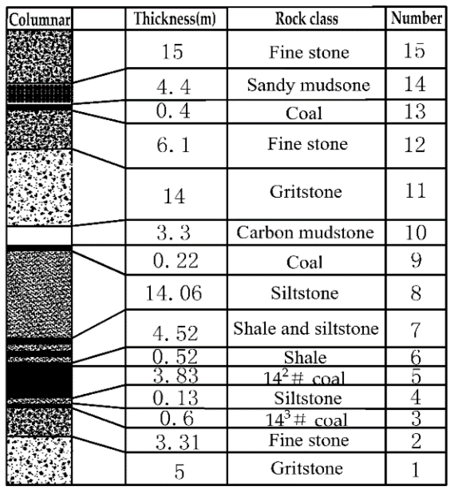
2.1. Geological Conditions

The 14# coal group of the Jurassic system in the Datong Mining Area consists of two minable seams. The upper seam is 142# coal seam and the lower seam is 143# coal seam. A dirt band with a thickness of 0.1–0.3 m is observed between the two seams. The 14# coal group has a large distribution in Silaogou mining field, with an average buried depth of 320 m and a dip-angle of 2–5°. The average thickness of minable sections is 4.6 m, where the fully mechanized top coal caving mining method is adopted. The 14 m thick siltstone layer above the 14# coal group is the HMR. The overlying stratum from the bottom to the top are shale, a mixture of shale and siltstone, and siltstone, for example. Furthermore, the layers of the 14# coal group are referred to as layer 1 to layer 15 from bottom to top, as shown in Figure 1.

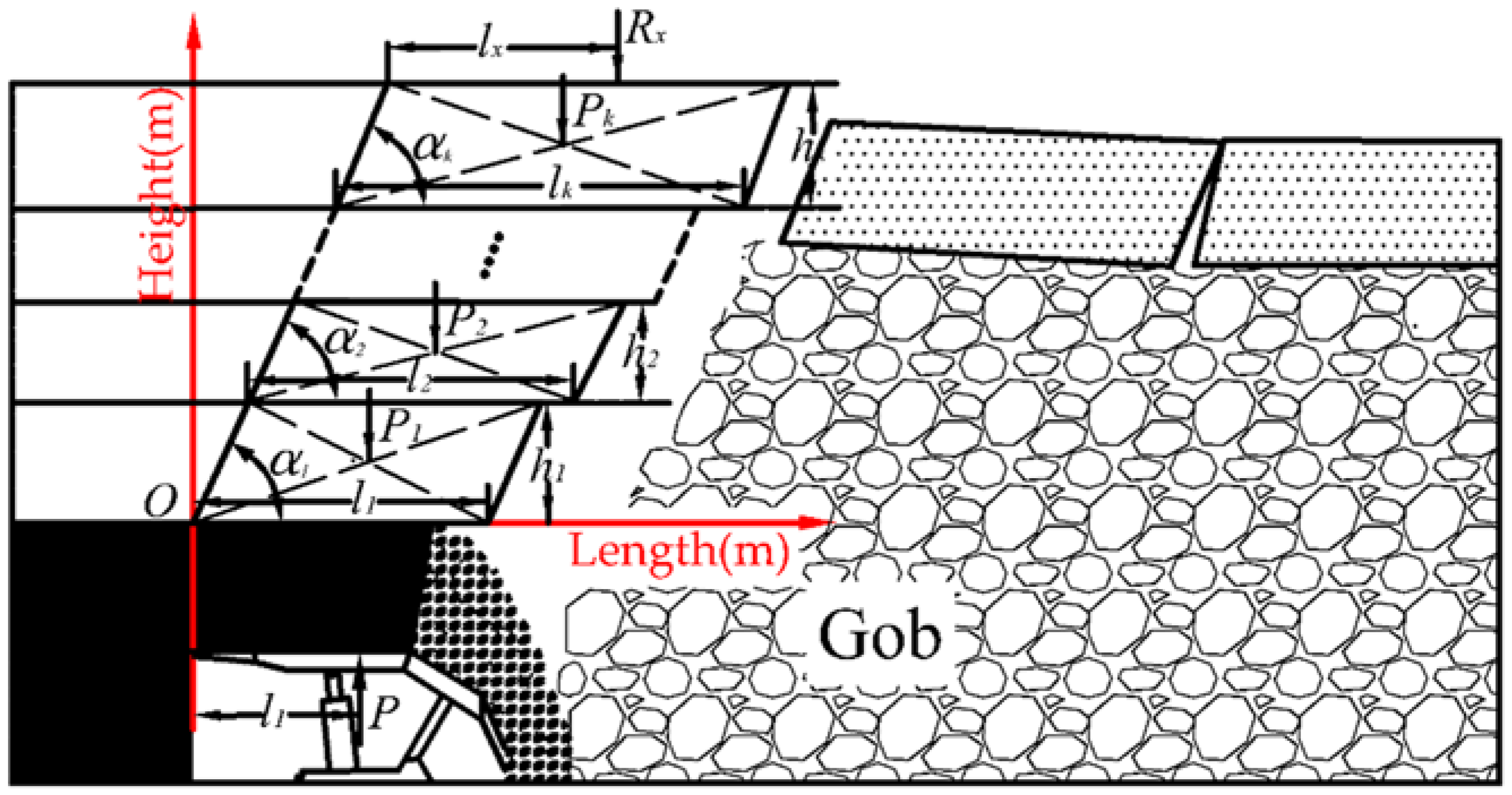
2.2. Mechanical Model of the HMR

In the mining process, the load on the overlying strata was mainly undertaken by the key strata, while the intermediate roof below the hinged structure of the overlying strata is in the form of a cantilever. The mechanical model of the cantilever beam of the immediate roof is illustrated in Figure 2.
As shown in Figure 2, P is the unit width of resistance of support; c is the horizontal distance between the equal resistance working point of the support and the coal wall, which is normally 0.6–0.75 times the face width; h1~hk are the individual layer thicknesses of the immediate roof, respectively; a1~ak are the individual layer fracture angles of the immediate roof, respectively, simplified as the same angle; k is the total layers of the immediate roof; P1~Pk are the individual layer weights of the cantilever, respectively; l1~lk are the rupture sizes of individual layers in the cantilever group, respectively, in which the length of the top one is no shorter than the bottom one; Rx is the additional load of the cantilever group from the articulated structure of the overlying strata cantilever; lx is the distance between the fracture line and the overlying strata load applying on layer x of the immediate roof.
According to the stress state of the cantilever group of the overlying strata, the moment of support force at the origin 0 in Figure 2 is MS, and the moment of the overlying strata at the origin 0 is MR. The stable condition of the cantilever structure is MSMR, as follows:
P c 1 2 P 1 ( h 1 cot α 1 + l 1 ) + P 2 ( 1 2 h 2 cot α 2 + 1 2 l 2 + h 1 cot α 1 ) + + P k ( 1 2 h k cot α k + 1 2 l k + i = 1 k 1 h i cot α i ) + R x ( l x + i = 1 k h i cot α i ) ,
According to Formula (1), the stable conditions of the cantilever group of the immediate roof under the hard and massive overlying strata are calculated as follows:
P c 1 2 i = 1 k P i ( h i cot α i + l i ) + j = 2 k i = 1 j 1 P j h i cot α i + R x ( l x + i = 1 k h i cot α i ) ,
According to Formula (2), in addition to the individual layers’ weight, thickness, fracture angle, fracture size, rational working resistance of support and working point position of support equal resistance, the stable conditions of the cantilever group of the overlying strata are also affected by the indirect force and the working point position from the fracture of the overlying rock in the cantilever group.

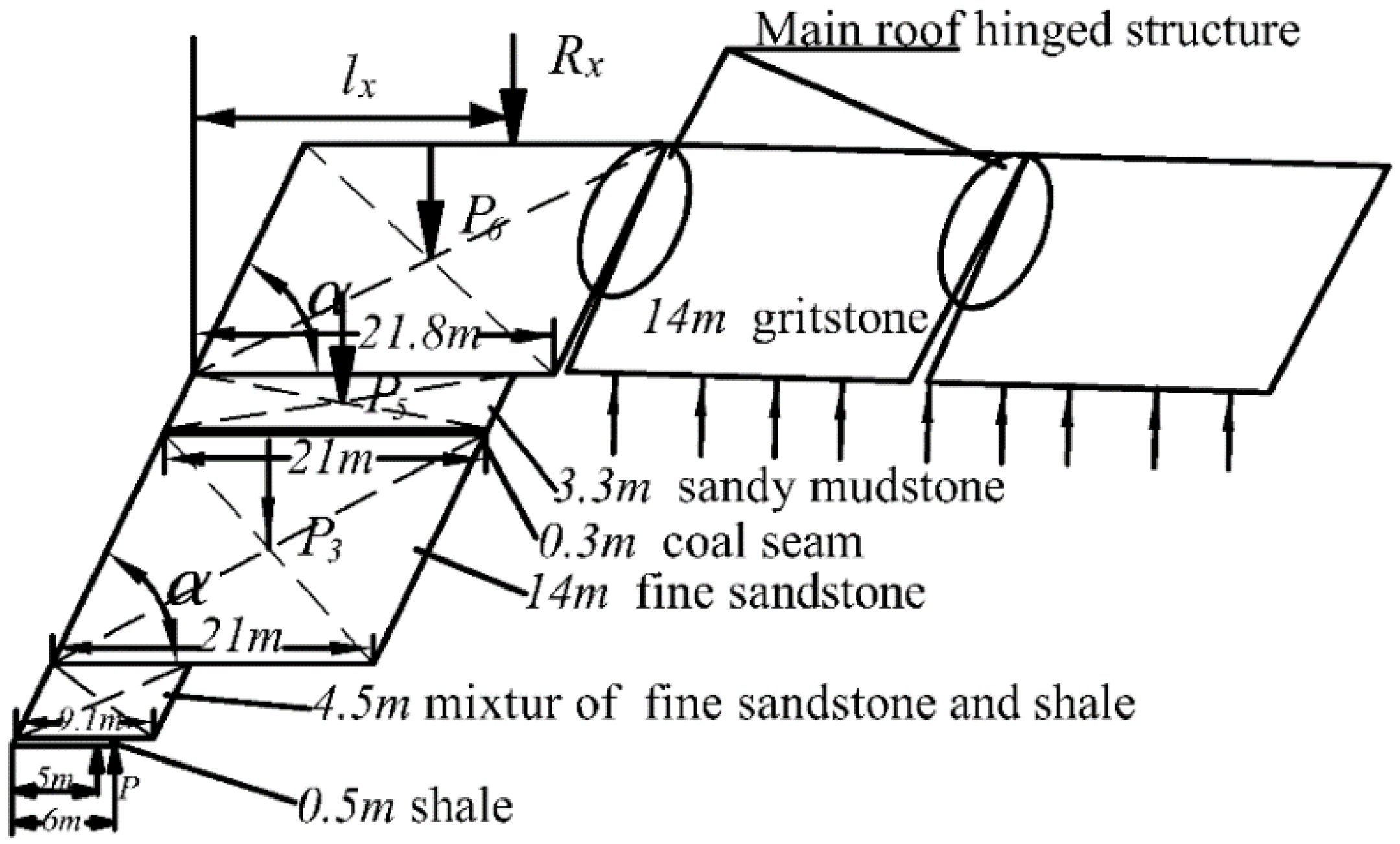
2.3. Thickness of Cantilever Group

Along with the proceedings of the coal mining, the smashed immediate roof collapsed and filled the gob, and the articulated structures were formed in the overlying strata.
Using the falling height from when the strata of the immediate roof filled the free space of the working face to evaluate the thickness of the roof of the cantilever group, the critical thickness (the layer number is an integer) of the cantilever of the immediate roof is calculated from Formula (3):
H z = h i ,
where
h = ( κ i 1 ) h i ,
Hz represents the total thickness of the layers in the cantilever group of the immediate roof (m); hi is the individual thickness of each strata of the roof (m); Ki′ is denoted as the bulking coefficient when individual rock strata collapses; h is the mining height of the working face (m).
Due to the variations in the lithology of the rock strata and the degree of fracture, the filling degree to the mined-out area could not be fixed. Based on on-site measurements, carbon mudstone fracture blocks were small, while the fine sandstone and medium-coarse sandstone were larger in size with a larger bulking coefficient. The bulking coefficients are shown in Table 1.
Owing to the existing support, the roof, which is hard to touch the gangue, would act as a cantilever before collapsing, and satisfy:
h ( κ i 1 ) h i ,
the parameters of the overlying strata in the coal group 14# were substituted into Formula (5):
1 5 ( κ i 1 ) h i = 4.45 4.6 1 6 ( κ i 1 ) h i = 4.78 ,
Thus, layers 1–5 are in the form of a cantilever. Considering Figure 1, the total thickness of the cantilever group is 22.6 m, composing of 0.5 m shale, 4.5 m mixture of shale and fine sandstone, 14 m fine sandstone, and 3.3 m carbon mudstone.

2.4. Strata Fracture Step

2.4.1. Load of Overlying Strata

The loads on each overlying strata are calculated as follows:
(a) The first layer is 0.52 m shale with low strength and directly to collapses with the coal layers. Therefore, this layer is not considered in this analysis.
(b) The load on the 4.5 m mixture of shale and fine sandstone in Layer 2 is
q 2 = γ 2 h 2 = 112.5   kN / m 2 ,
The load on Layer 2 caused by Layer 3 is
( q 3 ) 2 = E 2 h 2 3 ( γ 2 h 2 + γ 3 h 3 ) E 2 h 2 3 + E 3 h 3 3 = 11.892   kN / m 2 < q 2 ,
Compared to q2, the calculated load in Formula (8) is smaller than the gravity of Layer 3. Therefore, the (q3)2 is gravity of Layer 2 (i.e., 112.5 kN/m2).
(c) The load of Layer 3 composing of 14 m fine sandstone is
q 3 = γ 3 h 3 = 354.2   kN / m 2 ,
The load on Layer 3 caused by Layer 4 is
( q 4 ) 3 = E 3 h 3 3 ( γ 3 h 3 + γ 4 h 4 ) E 3 h 3 3 + E 4 h 4 3 = 358.4   kN / m 2 > q 3 ,
The load on Layer 3 caused by Layer 5 is
( q 5 ) 3 = E 3 h 3 3 ( γ 3 h 3 + γ 4 h 4 + γ 5 h 5 ) E 3 h 3 3 + E 4 h 4 3 + E 5 h 5 3 = 435.637   kN / m 2 > ( q 4 ) 3 ,
The load on Layer 3 caused by Layer 6 is
( q 6 ) 3 = E 3 h 3 3 ( γ 3 h 3 + γ 4 h 4 + γ 5 h 5 + γ 6 h 6 ) E 3 h 3 3 + E 4 h 4 3 + E 5 h 5 3 + E 6 h 6 3 = 429.629   kN / m 2 < ( q 5 ) 3 ,
As discussed earlier, the load was 435.637 kN/m2.
(d) Layer 4 is as thin as 0.22 m, and will collapse with the layers below due to its low strength. Thus, it is not counted.
(e) The load of Layer 5 which is composed of 3.3 m sandy mudstone is
q 5 = γ 5 h 5 = 82.5   kN / m 2 ,
Since Layer 6 is composed of medium-coarse sandstone and its elasticity modulus and thickness is far larger than 3.3 m sandy mudstone, it is the support layer. Therefore, the load of Layer 5 is gravity, i.e., 82.5 kN/m2.
(f) The load of Layer 6 which is composed of 14 m medium-coarse sandstone is
q 6 = γ 6 h 6 = 354.76   kN / m 2 ,
The load on Layer 6 caused by Layer 7 is
( q 7 ) 6 = E 6 h 6 3 ( γ 6 h 6 + γ 7 h 7 ) E 6 h 6 3 + E 7 h 7 3 = 463.529   kN / m 2 > q 6 ,
The load on Layer 6 caused by Layer 8 is
( q 8 ) 6 = E 6 h 6 3 ( γ 6 h 6 + γ 7 h 7 + γ 8 h 8 ) E 6 h 6 3 + E 7 h 7 3 + E 8 h 8 3 = 465.675   kN / m 2 > ( q 7 ) 6 ,
The load on Layer 6 caused by Layer 9 is
( q 9 ) 6 = E 6 h 6 3 ( γ 6 h 6 + γ 7 h 7 + γ 8 h 8 + γ 9 h 9 ) E 6 h 6 3 + E 7 h 7 3 + E 8 h 8 3 + E 9 h 9 3 = 550.966   kN / m 2 > ( q 8 ) 6 ,
The load on Layer 6 caused by Layer 10 is
( q 10 ) 6 = E 6 h 6 3 ( γ 6 h 6 + γ 7 h 7 + γ 8 h 8 + γ 9 h 9 + γ 10 h 10 ) E 6 h 6 3 + E 7 h 7 3 + E 8 h 8 3 + E 9 h 9 3 + E 10 h 10 3 = 386.009   kN / m 2 < ( q 9 ) 6 ,
Thus, 15 m fine sandstone had no effect on 14 m medium-coarse sandstone, and the load of 14 m medium-coarse sandstone is 550.966 kN/m2.

2.4.2. Naturally Fracture Step and the Working Resistance of Supports

Based on the effects of gangues in the gob area on the roof, the periodic step of the cantilever could be calculated by using the step calculation formula which includes the supporting effect and conventional formula.
{ L s = h R t / 3 n q L s = 0.58 h R t / q ,
Combined with Formula (19), the length of the cantilever of the immediate roof is defined as
L z = max ( L s ) ,
Here, Ls is the periodic fracture step of Layer i of the roof under two circumstances. Lz is the periodic fracture step of Layer i of the roof based on the whole rock strata of hard overlying strata.
As the properties and the loading conditions of the overlying stratum are different, the limit step varied with each layer. When the fracture step of the lower layer of a cantilever is larger than the upper layer, the fracture step of the upper thin and soft overlying rock is consistent with that of the lower one due to the effect of long fracture step of lower layer of the hard and massive overlying rock. In this case, the fracture step of the upper layer is the same as the maximum value of the lower layer, thus controlling the weight of the upper layer and suppressing the increase of the fracture step. Considering the fracture angle of the layers, the cantilever group displayed an inverted trapezoidal structure. Parameters including the fracture step and the cantilever length of each layer are shown in Table 2.
As shown in Table 2, since the fracture step of 14 m fine sandstone is longer than that of 3.3 m mudstone, all fracture angles of all layers are normalized to the fracture angle of sandstone. Meanwhile, the fracture step of 14 m fine sandstone and that of 14 m medium-coarse sandstone is nearly the same. Hence, the additional load from the upper roof of the articulated strata on the immediate cantilever should be considered. The mechanical model is built and illustrated in Figure 3.
The stable conditions of the support are:
P c 1 2 P 1 ( h 1 cot α + l 1 ) + P 2 ( 1 2 h 2 cot α + 1 2 l 2 + h 1 cot α ) + P 3 ( 1 2 h 3 cot α + 1 2 l 3 + h 1 cot α + h 2 cot α ) + + P 5 ( 1 2 h 5 cot α + 1 2 l 5 + i = 1 4 h i cot α ) + R x ( l x + i = 1 5 h i cot α ) ,
Besides the volume weight of the articulated strata and the additional moment to the cantilever from its own load, Rx can be simplified as:
R x = f P 6 + K P x ,
where f is the equal gravity coefficient; K is the equal load coefficient of medium-coarse strata; lx~Rx are the equal function positions. Substituting the limit cantilever parameter of the roof into Formulas (21) and (22), it can be simplified to:
P 27516 + R x 5 ( l x + i = 1 5 h i cot α ) ,
On the basis of real production at working face, when the working face proceeds normally, the work resistance of the support at working face should be larger than 27.5 MN, inclusive of any additional load on the overlying strata from a long cantilever. The current support types cannot ensure safe production at working face. Therefore, measurements should be taken to control the cyclic step of the roof and to reduce the pressure, and to make sure the requirements on support resistance and stability.

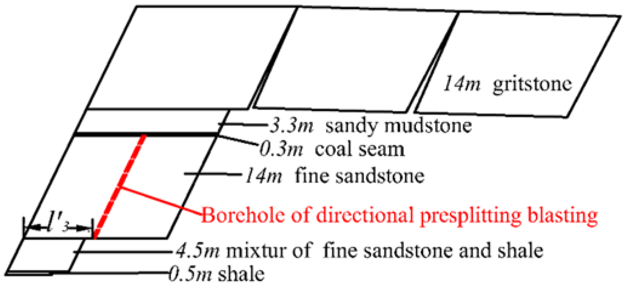
3. Blasting Parameters for Fracture of HMR

High pressure will present when the working face proceeds normally and when the current supports cannot ensure safe and effective production, the 14 m fine sandstone should be treated. In the present paper, the presplitting and blasting methods were applied to effectively reduce the cyclic fracture step of the roof. The model of blasting is shown in Figure 4.
After blasting, the step of the 14 m fine sandstone seam was dramatically different to that of 14 m medium-coarse sandstone. In this case, the articulated structure could form in 14 m medium-coarse sandstone, supporting the load from the overlying strata. The effect on the support from the weight of the articulated structure and the overlying strata load will decrease, and even vanish, with the decreasing length of limit cantilever. The stable conditions of the support are
P c 1 2 P 1 ( h 1 cot α + l 1 ) + P 2 ( 1 2 h 2 cot α + 1 2 l + h 1 cot α ) + P 3 ( 1 2 h 3 cot α + 1 2 l + h 1 cot α + h 2 cot α ) + + P 5 ( 1 2 h 5 cot α + 1 2 l + i = 1 4 h i cot α ) ,
Substituting the specific parameters into the formula, it could be simplified to
P 44.09 l 2 + 1211.761 l cot α + 566.95 cot α + 974.1 ,
According to the safe production at the working face, the relationship between the fracture step of the roof and the fracture angle of the strata of 4 types of supports were compared. These are shown in Figure 5.
It can be seen from Figure 5, along with the increase of the fracture angle of the strata, that the maximum fracture step of the roof was enlarged progressively, whereas the enlarging rate tended to decrease. This indicates that under certain work resistance of the support and under certain fracture angles of strata, the larger fracture angle has less of an effect on controlling the fracture step of the roof. When the fracture angle was constant, with the increasing of the support resistance from 7600 to 9900 kN, the fracture step increased significantly from 9.2 to 10.6 m. However, when the resistance increased from 9900 to 11,000 kN, and then to 12,000 kN, the fracture step varied slightly from 10.6 to 11 m, and then 11.5 m. At the largest fracture angle (90°), the cyclic presplitting fracture step was 10 m. Furthermore, at the work resistance of 9900 kN, the economic and technical income was the highest. Considering the production reality and the current four types, the support type is determined to be ZZ9900/29.5/50, and the cyclic presplitting and blasting step is 10 m. Meanwhile, based on the requirements of techniques and economics, the presplitting drill is set up to be paralleled with the working face.

4. On-Site Application and Effect Analysis

4.1. On-Site Blasting Parameters at Working Face

Based on the conditions of 8402 working face, which was assigned in the coal group 14# belong to the Silaogou Coal Mine in the Datong Mining Area, and the existing conditions of overlying strata and arrangement parameters of presplitting holes calculated in Section 3. The key parameters including drill length and diameter, space between two drills, loaded length and loaded volume, and hole sealing length are listed in Table 3.
The distributions of boreholes in the roof for directional pre-splitting blasting are shown in Figure 6.

4.2. Blasting Affect

To investigate the effects of presplitting and blasting by the borehole, water from the cracks of neighboring holes and water volume were used to evaluate the crack status, following the presplitting and blasting. The presence of cracks and the crack directions after blasting varied with drill construction and the geology conditions. The ground pressure behaviors at 8402 working face was applied to demonstrate that presplitting and blasting could decrease mine pressure and ensure safe production.
The water-carrying capacity changed after blasting occurred. To test the water injection, one of the two neighboring holes acted as the injection hole, while the other acted as the testing hole. When water came out of the hole, the crack from the blasting of the two holes could extend to the middle of the holes.
Instruments were installed to hydraulic supports 7, 15, 28, 38, 50, 58, 68, 78, 92, and 102, respectively, and the pressure values were recorded in the front and back columns of the hydraulic support at an interval of 5 min.
Figure 7 indicates the load changes with the proceeding of working face of Support 7, 50, and 102. The results from the measurements reveal that the first fracture steps of the tip, the middle part, and the tail of working face were 59.8 m, 56.3 m, and 59.8 m, with an average of 58.9 m. The first fracture step of the working face of the upper roof was large and dynamic factor reached 1.39. The cyclic pressure step of the upper roof was 10–12 m, with an average of 11.1 m.
According to the measuring working load data of support, every load under each status of the plots, pressure step, and strength of the upper roof were analysed, and these results are shown in Table 4 and Table 5. The setting load was measured as 6260 kN, with an average of 81% of the expected setting load. The final load was 7436 kN, while the average load was 76.11% of the expected final load. The average of the time weighted load was 6553 kN, which was 66.19% of the expected value. The maximum was 8445 kN/support, which was 85.31% of the expected value. The sufficient safe space between 8445 kN and 9900 kN demonstrated the excellent adaptability of Workface 8402.

5. Conclusions

(1)
The mechanical model for the hinge balanced cantilever beam structure of the HMR was established. Then, the stability conditions and the influencing factors of the cantilever beams were determined.
(2)
Combined with the actual production background of the Silaogou coal mine working face in the Datong mining area, the thickness of the roof in a cantilevered state in the mining process was analyzed. The breaking form, order, and step of each roof were determined. The reasonable working resistance was calculated under the natural breaking condition of the roofs, and the result being a safe working resisitance could not be achieved. Hence, the presplitting blasting method was presented for treating the key strata of the HMR, and the reasonable breaking step and working resistance of the support were obtained through calculation. The blasting parameters in the field of working face were also determined.
(3)
The field test shows that the roof presplitting blasting successfully controlled the breaking step distance of the critical layer of the roof, effectively slowed down the mining pressure, and provided the basis for the mining of similar conditions. In future, high efficiency blasting techniques will be researched to effectively enhance the control of the HMR, increasing the safety of workers and the efficiency of mining operations at the working face.

Author Contributions

C.L. put forward the research ideas and methods; N.Z. carried out the theoretical analysis; B.C. collect the field data; N.Z. wrote the paper.

Acknowledgments

Financial support for this work, provided by the National Natural Science Foundation of China (Grant No. 51704275 and No. 51574220), China Postdoctoral Science Foundation (Grant No. 2016M601914), and Independent Research Project of State Key Laboratory of Coal Resources and Safe Mining, China University of Mining and Technology, are gratefully acknowledged.

Conflicts of Interest

The authors declare no conflict of interest.

References

  1. Zhao, T.; Liu, C.Y.; Yetilmezsoy, K.; Zhang, B.S.; Zhang, S. Fractural structure of thick hard roof stratum using long beam theory and numerical modeling. Environ. Earth Sci. 2017, 76, 751. [Google Scholar] [CrossRef]
  2. Zhang, J.X.; Li, B.Y.; Zhou, N.; Zhang, Q. Application of solid backfilling to reduce hard-roof caving and longwall coal face burst potential. Int. J. Rock Mech. Min. Sci. 2016, 88, 197–205. [Google Scholar] [CrossRef]
  3. Liu, C.; Li, H.M.; Mitri, H.; Jiang, D.J.; Li, H.G.; Feng, J.F. Voussoir beam model for lower strong roof strata movement in longwall mining—Case study. J. Rock Mech. Geotech. Eng. 2017, 9, 1171–1176. [Google Scholar] [CrossRef]
  4. Galvin, J.; Hebblewhite, B. Geomechanics developments in mining coal under strong roof and weak floor conditions. In Proceedings of the Ninth International Congress on Rock Mechanics, Paris, France, 25–28 August 1999; pp. 277–281. [Google Scholar]
  5. Ning, J.G.; Wang, J.; Jiang, L.S.; Jiang, N.; Liu, X.S.; Jiang, J.Q. Fracture analysis of double-layer hard and thick roof and the controlling effect on strata behavior: A case study. Eng. Fail. Anal. 2017, 81, 117–134. [Google Scholar] [CrossRef]
  6. Shabanimashcool, M.; Li, C.C. Analytical approaches for studying the stability of laminated roof strata. Int. J. Rock Mech. Min. Sci. 2015, 79, 99–108. [Google Scholar] [CrossRef]
  7. Li, M.; Zhou, N.; Zhang, J.X.; Liu, Z.C. Numerical modelling of mechanical behavior of coal mining hard roofs in different backfill ratios: A case study. Energies 2017, 10, 1005. [Google Scholar]
  8. Guo, W.J.; Li, Y.Y.; Yin, D.W.; Zhang, S.C.; Sun, X.Z. Mechanisms of rock burst in hard and thick upper strata and rock-burst controlling technology. Arab. J. Geosci. 2016, 9, 561. [Google Scholar] [CrossRef]
  9. Zubelewicz, A.; Mroz, Z. Numerical-simulation of rock burst processes treated as problems of dynamic instability. Rock Mech. Rock Eng. 1983, 16, 253–274. [Google Scholar] [CrossRef]
  10. Lu, C.P.; Liu, G.J.; Liu, Y.; Zhang, N.; Xue, J.H.; Zhang, L. Microseismic multi-parameter characteristics of rockburst hazard induced by hard roof fall and high stress concentration. Int. J. Rock Mech. Min. Sci. 2015, 76, 18–32. [Google Scholar] [CrossRef]
  11. Shik, V.M. Value of the longwall length as a regulator of the intensity of geomechanical processes on beds with strong roof rocks. J. Min. Sci. 1992, 28, 1–5. [Google Scholar] [CrossRef]
  12. Chernov, O.I. Hydrodynamic stratification of petrologically uniform strong rocks as a means of controlling intransigent roofs. Sov. Min. 1982, 18, 102–107. [Google Scholar] [CrossRef]
  13. Zhang, N.B.; Liu, C.Y. Radiation characteristics of natural gamma-ray from coal and gangue for recognition in top coal caving. Sci. Rep. UK 2018, 8, 190. [Google Scholar] [CrossRef] [PubMed]
  14. Zhang, N.B.; Liu, C.Y.; Yang, P.J. Flow of top coal and roof rock and loss of top coal in fully mechanized top coal caving mining of extra thick coal seams. Arab. J. Geosci. 2016, 9, 465. [Google Scholar] [CrossRef]
  15. Guo, W.B.; Wang, H.S.; Dong, G.W.; Li, L.; Huang, Y.G. A case study of effective support working resistance and roof support technology in thick seam fully-mechanized face mining with hard roof conditions. Sustainability 2017, 9, 935. [Google Scholar] [CrossRef]
  16. Yang, J.X.; Liu, C.Y.; Yu, B. Application of confined blasting in water-filled deep holes to control strong rock pressure in hard rock mines. Energies 2017, 10, 1874. [Google Scholar] [CrossRef]
  17. Zhang, Z.Y.; Zhang, N.; Shimada, H.; Sasaoka, T.; Wahyudi, S. Optimization of hard roof structure over retained goaf-side gateroad by pre-split blasting technology. Int. J. Rock Mech. Min. Sci. 2017, 100, 330–337. [Google Scholar] [CrossRef]
  18. Shimada, H.; Matsui, K.; Anwar, H. Control of hard-to-collapse massive roofs in longwall faces using a hydraulic fracturing technique. In Proceedings of the 17th International Conference on Ground Control in Mining, Wollongong, Australia, 14–17 July 1998; pp. 79–87. [Google Scholar]
  19. Koehler, M.; Carey, J. Blasting techniques to control roof failure in an underground limestone mine. In Proceedings of the Twenty-Eighth Annual Conference on Explosives and Blasting Technique, Las Vegas, NV, USA, 10–13 February 2002; pp. 91–102. [Google Scholar]
  20. Matsui, K.; Shimada, H.; Anzwar, H.Z. Acceleration of massive roof caving in a longwall gob using a hydraulic fracturing. Min. Sci. Technol. 1999, 99, 43–46. [Google Scholar]
  21. Jiang, J.Q.; Dai, J.; Wang, P.; Zhang, L.L. Overlying hard and thick strata breaking movement and broken-roof control. Rock Soil Mech. 2014, 35, 264–270. [Google Scholar]
  22. Sawmliana, C.; Roy, P.P. A new blastability index for hard roof management in blasting gallery method. Geotech. Geol. Eng. 2012, 30, 1357–1367. [Google Scholar] [CrossRef]
  23. Liu, C.Y.; Yang, J.X.; Yu, B. Rock-breaking mechanism and experimental analysis of confined blasting of borehole surrounding rock. Int. J. Min. Sci. Technol. 2017, 27, 795–801. [Google Scholar]
  24. Huang, B.X.; Chen, S.L.; Zhao, X.L. Hydraulic fracturing stress transfer methods to control the strong strata behaviours in gob-side gateroads of longwall mines. Arab. J. Geosci. 2017, 10, 236. [Google Scholar] [CrossRef]
  25. Chong, Z.H.; Li, X.H.; Chen, X.Y.; Zhang, J.; Lu, J.Z. Numerical investigation into the effect of natural fracture density on hydraulic fracture network propagation. Energies 2017, 10, 914. [Google Scholar] [CrossRef]
  26. Zhao, D.; Feng, Z.C.; Zhao, Y.S. Effects and Influences of Water Injection on Coalbed Exploitation in Mining Engineering; Crc Press-Taylor & Francis Group: Boca Raton, FL, USA, 2012; pp. 731–735. [Google Scholar]
  27. Zhou, N.; Zhang, J.X.; Yan, H.; Li, M. Deformation behavior of hard roofs in solid backfill coal mining using physical models. Energies 2017, 10, 557. [Google Scholar] [CrossRef]
  28. Verma, H.K.; Samadhiya, N.K.; Singh, M.; Goel, R.K.; Singh, P.K. Blast induced rock mass damage around tunnels. Tunn. Undergr. Space Technol. 2018, 71, 149–158. [Google Scholar] [CrossRef]
  29. Bendezu, M.; Romanel, C.; Roehl, D. Finite element analysis of blast-induced fracture propagation in hard rocks. Comput. Struct. 2017, 182, 1–13. [Google Scholar] [CrossRef]
  30. Singh, P.K.; Roy, M.P.; Paswan, R.K.; Sarim, M.; Kumar, S.; Jha, R.R. Rock fragmentation control in opencast blasting. J. Rock Mech. Geotech. Eng. 2016, 8, 225–237. [Google Scholar] [CrossRef]
  31. Piyush, R.; Hakan, S.; Per-Arne, L.; Uday, K. Measurement-while-drilling technique and its scope in design and prediction of rock blasting. Int. J. Min. Sci. Technol. 2016, 26, 711–719. [Google Scholar]
  32. Yang, J.X.; Liu, C.Y. Experimental study and engineering practice of pressured water coupling blasting. Shock Vib. 2017, 2017, 5484598. [Google Scholar] [CrossRef]
  33. Li, T.C.; Liu, H.Q.; Wang, C. Study of millisecond blasting technology of shaft excavation by one-step deep-hole blasting. Rock Soil Mech. 2012, 33, 1742–1746. [Google Scholar]
  34. Wei, J.P. Numerical simulation of hard roof’s safety control. Prog. Saf. Sci. Tech. 2006, 6, 1792–1795. [Google Scholar]
  35. Liu, C.Y.; Yang, J.X.; Yu, B.; Wu, F.F. Support resistance determination of fully mechanized top-coal caving face in extra thick seam under multi-layered hard strata. J. Min. Saf. Eng. 2015, 32, 7–13. [Google Scholar]
Figure 1. The composite columnar section.
Energies 11 01363 g001
Figure 2. Cantilever beam mechanical model of the immediate roof.
Energies 11 01363 g002
Figure 3. Mechanical model of cantilever of immediate roof.
Energies 11 01363 g003
Figure 4. The blasting model of the cantilever.
Energies 11 01363 g004
Figure 5. Relationship between the fracture step and the fracture angle at different work resistances of the support.
Energies 11 01363 g005
Figure 6. Distributions of boreholes in the roof for directional pre-splitting blasting at (a) horizontal position, (b) vertical position.
Energies 11 01363 g006
Figure 7. Relationship between the work load and the proceeding distance of the open-off cut at (a) support 7, (b) support 50, and (c) support 102.
Energies 11 01363 g007
Table 1. Expansion coefficients of the overlying strata.
LithologySandy MudstoneShaleFine SandstoneMedium-Coarse SandstoneCoal
Expansion coefficient1.11.11.251.21.2
Density/kg/m325002500253025301400
Table 2. Fracture step of each layer of the cantilever.
Layer NumberLithologyThickness/mDensity/kg/m3Elasticity Modulus/GpaLoad of Strata/kN/m2Tensile Strength/MpaFracture Step/mLimit Length of Cantilever/mWeight/kN/m
10Fine sandstone15253025.4-8.9---
9Chiltern4.4250023.43-4---
8Coal seam0.414262.82.6---
7Fine sandstone6.1253025.48.9---
6Medium-coarse sandstone14253021.3550.966821.821.87722
5Sandy mudstone3.3250023.4382.446.7211741
4Coal seam0.314002.8-2.6-2189
3Fine sandstone14253025.4435.6378.921.1217474
2Shale and siltstone4.5253020.0112.56.99.191024
1Shale0.52500-12.55.4-775
Table 3. Blasting parameters for practical applications.
ProgramUnitsHole
A1B1A2B2A3B3A4B4A5B5A6B6
Perf lengthm25.432.844.452.67474.2
Perf horizontal angle 909090909090
Perf vertical angle 50372618137
No. 111111
Drill diametermm606060606060
Explosive densitykg/m3105010501050105010501050
Detonating velocitym/s554055405540554055405540
Explosive payload per meterkg/m3.293.293.293.293.293.29
Loaded lengthm16.921.929.635.149.349.5
Loaded weightkg1012.717.220.12424.2
Filling lengthm8.510.914.817.524.624.7
Detonating fuse lengthm27.434.846.454.67676.2
No. of detonators 222222
No. of segments of detonators 212121212121
Explosive typeEmulsion explosive
Table 4. Pressure step and strength of the main roof.
Pressure PropertyLocationPressure ProcedureDynamic Load km
Function TimeEffecting Scope/mPressure Step/m
CycleDays
Setting load of the upper roof1tip
middle
tail
3
3
2
0.4
0.7
0.3
2
2.6
1.7
58.9
55.5
58.9
1.38
1.42
1.38
average 3.30.52.157.81.39
Cyclic load of the upper roof1tip
middle
tail
3
5
6
1
0.4
1
2.6
4.4
5.2
12.6
10.5
11.2
1.27
1.36
1.36
average 4.70.84.111.41.33
2tip
middle
tail
5
7
3
3.2
2
0.2
4.3
6.1
2.6
11.9
9.6
10.8
1.35
1.37
1.32
average 51.83.310.81.35
Table 5. Supporting strength of the support.
ProgramTesting LineSupporting Resistance/kNSupporting Resistance/kN·m−2
AverageMean Square ErrorMaximumAverageMaximumRatioNo. of Cycles
Setting loadTip5647.61535.47129 52
Middle3944.61415.68918.5
Tail62401562.77273.4
Average62601504.67773.6559.3886.60.63
Final resistanceTip59261605.36782.6
Middle8797.51290.59871
Tail7544.116718168
Average74361522.38273.9473.6836.50.57
Time weighted resistanceTip5456.34391.46678.3
Middle731212828220
Tail68351380.47811
Average65532351.37869.8

