Article

On the Heat Transfer Enhancement of Plate Fin Heat Exchanger

1
Key Laboratory of Condition Monitoring and Control for Power Plant Equipment, Ministry of Education, North China Electric Power University, Beijing 102206, China
2
School of Energy and Power Engineering, Lanzhou University of Technology, Lanzhou 730050, China
*
Authors to whom correspondence should be addressed.
Energies 2018, 11(6), 1398; https://doi.org/10.3390/en11061398
Submission received: 21 April 2018 / Revised: 10 May 2018 / Accepted: 15 May 2018 / Published: 30 May 2018
(This article belongs to the Section I: Energy Fundamentals and Conversion)

Abstract

:
The plate fin heat exchanger is a compact heat exchanger applied in many industries because of its high thermal performance. To enhance the heat transfer of plate fin heat exchanger further, three new kinds of wavy plate fins, namely perforated wavy fin, staggered wavy fin and discontinuous wavy fin, are proposed and investigated by computational fluid dynamics (CFD) simulations. The effects of key design parameters, including that of waviness aspect ratios, perforation diameters, staggered ratios and breaking distance are investigated, respectively, with Reynolds number changes from 500 to 4500. It is found that due to the swirl flow and efficient mixing of the fluid, the proposed heat transfer enhancement techniques all have advantages over the traditional wavy fin. At the same time, serration is beneficial to reduce the friction factor, and the breaking technique can reduce heat transfer area. Through the performance evaluation criteria, the staggered wavy fin has an advantage over the small waviness aspect ratio; with increasing waviness aspect ratio, this predominance is gradually surpassed by the perforated wavy fin, and the advantage of the discontinuous fin is the smallest and almost invariable. A maximum performance evaluation criteria (PEC) as high as 1.24 can be obtained for the perforated wavy fin at the waviness aspect ratio γ = 0.45.

1. Introduction

As a compact heat exchanger, the plate fin heat exchanger is applied in many industries and occupies a unique role due to its flexible arrangement, simple shape, and good thermal effectiveness. Based on different applications, various kinds of fins are used in plate fin heat exchangers, such as plain, offset-strip, louvered, wavy and pin [1,2,3,4,5]. Kays and London conducted an experimental analysis of about 40 kinds of fins and offered the corresponding correlation curves of heat transfer and resistance [6]. Khoshvaght-Aliabadi investigated seven common configurations of channels used in plate fin heat exchangers experimentally. The results showed that a vortex-generator channel can be applied as a high-quality interrupted surface, and wavy channel displayed an optimal performance in low Reynolds numbers [7]. Juan Du carried out experimental and numerical investigations of the heat transfer and pressure drop characteristics of an offset plate fin heat exchangers for cooling of lubricant oil [8]. Numerical simulations and experimental study on the flow and heat transfer characteristics of air in wavy fin were carried by Dong. The results show that the waviness amplitude has a significant effect on the heat transfer and pressure drop of wavy fin [9].
More recently, there has been various research on the development of new types of fin for heat transfer enhancement [10,11,12], including that of offset strip fins compact heat exchanger [13], fins with grooves or vortex generators [14,15]. El Hassan Ridouane found that the grooves on the fin surface can enhance local heat transfer significantly [16]. The numerical simulation also found that the multi-row windward punched delta winglet on the plain fin has much enhanced performance [17]. Both experiment and numerical simulations have been conducted to investigate the air-side flow and heat transfer of the wavy fin with or without delta winglet pairs punched on the surface. The results showed that the wavy fin with delta winglet pairs can significantly enhance air-side heat transfer and pressure drop [18]. Thermal characteristics of the plan and curved vortex generators with or without punching holes in the fin surface were investigated, indicating that vortex generators with holes have higher heat transfer enhancement and lower pressure drop than those without holes [19]. In order to resolve the shortcomings of the louver fin heat exchanger, Chan Hyeok Jeong developed the plate fin with both ceases and holes, which helped to improve heat transfer and could be used under hostile environments [20]. The effects of round and elongated holes were also compared [21]. It was found that the elongated holes offered better performance but also with larger pressure drops.
Among the numerous studies on the different kinds of fins, wavy and offset strip fins are the most popular ones because of their high thermal performances. Punching holes on the fin surface can enhance heat transfer significantly. However, there have hitherto been few studies regarding the effects of the staggered arrangement on wavy fins. In the present study, three new kinds of wavy plate fin configurations are considered by numerical investigations. The benefits of heat transfer and pressure drop of the plate fin heat exchanger have analyzed accordingly.

2. Physical and Mathematic Model
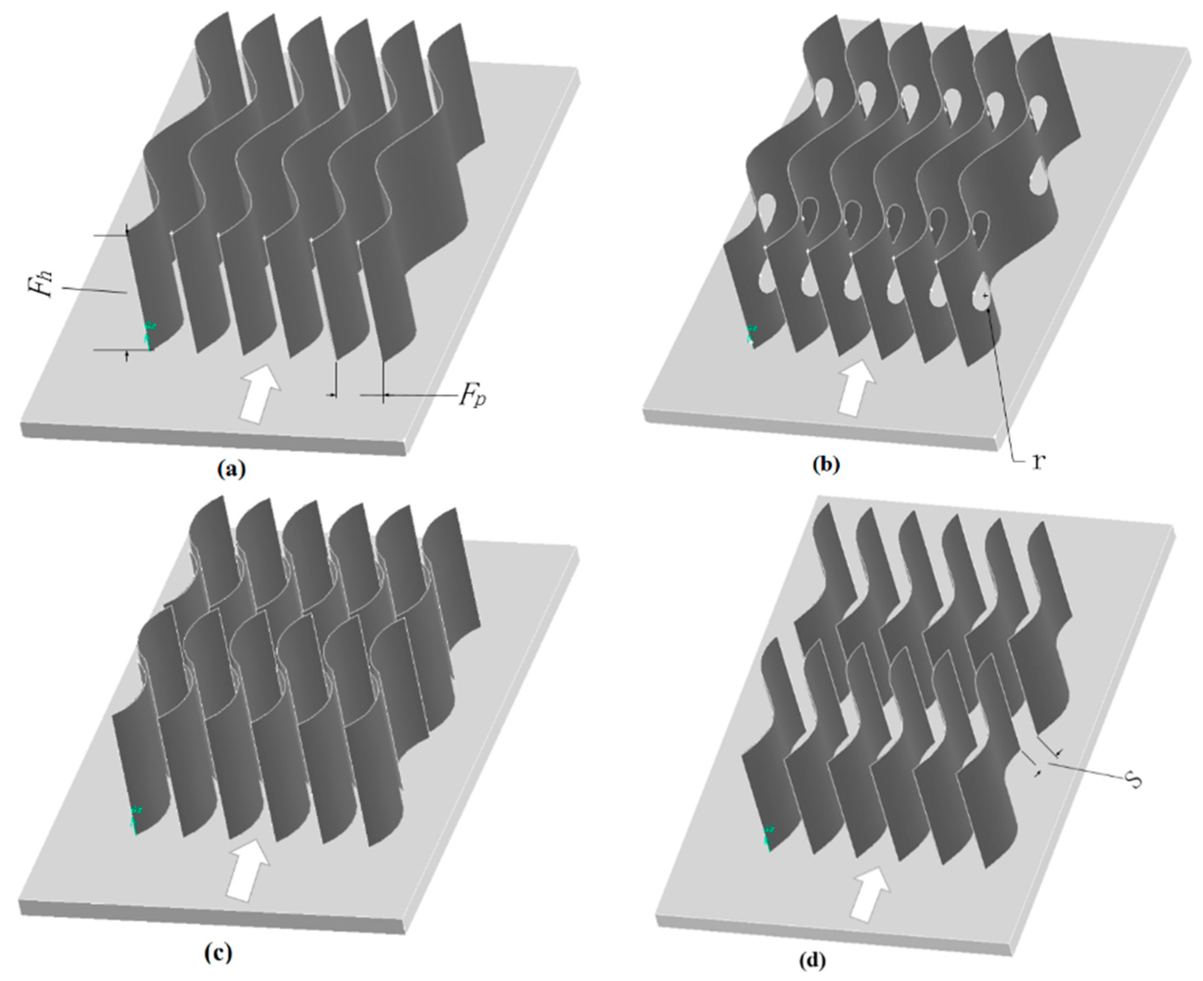
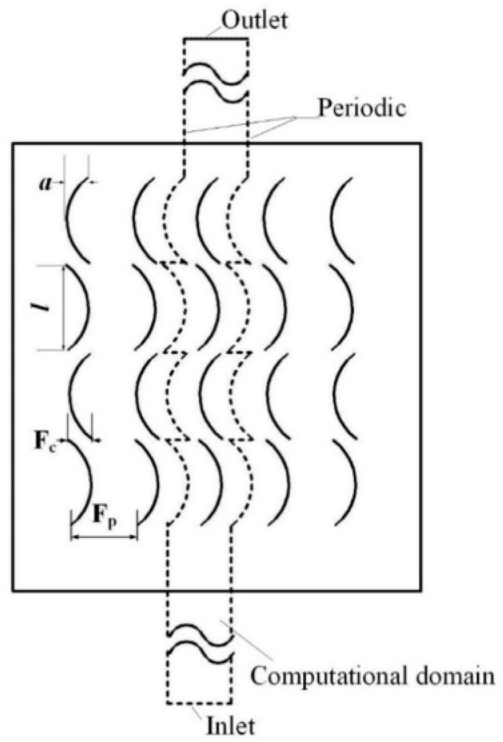
2.1. Physical Model

The heat transfer performance and flow resistance of four kinds of wavy plate fins are evaluated using computational numerical analysis. Figure 1 shows the shape and geometric details of the objective wavy fins. Compared with the traditional wavy fin, three enhanced configurations, shown in Figure 1b–d, were also investigated to verify their heat transfer performances, including that of the perforated wavy fin, staggered wavy fin, and discontinuous wavy fin, in which, F h is the fin height; F p is the fin pinch; r is the perforation radius; S is the breaking distance in discontinuous fin.

2.2. Governing Equations

The continuity, momentum, and energy equations are listed as follows, which govern the three-dimensional, steady-state flow of air flowing in the proposed wavy fin passage.
( ρ u i ) x i = 0
( ρ u i u j ) x i = p x i + x j ( τ i j ρ u i u j ¯ )
x i ( ρ u i C p T ) = x i ( λ T x i )
where ρ is the fluid density; u i and u j are the velocity in the i and j direction; x i is the coordinate; p is the pressure, τ is the shear stress; C p is the specific heat; T is the temperature; λ is the thermal conductivity.
In which,
τ i j = μ ( u i x j + u j x i 2 3 δ i j u k x k )
ρ u i u j ¯ = μ t ( u i x j + u j x i 2 3 δ i j u k x k ) 2 3 δ i j ρ k
k = u i u j ¯ 2
in which, μ is the dynamic viscosity; μ t is the turbulent viscosity; δ i j is the Kronecker delta; k is the turbulence kinetic energy.
The standard k ε model, low Re k ε model, RNG k ε model and k ω SST model are used as turbulent models for verification of calculation, finally, the RNG k ε is selected because of the minimum error between the results and reference experimental data (For details, see Section 3.1). For the RNG k ε model, the turbulence kinetic energy, k , and dissipation rate, ε , are calculated as,
x i ( ρ k u i ) = x j [ ( μ + μ t σ k ) k x j ] + G k ρ ε
x i ( ρ ε u i ) = x j [ ( μ + μ t σ ε ) ε x j ] + C 1 ε ε k G k C 2 ε ρ ε 2 k
and with the model constants as C 1 ε = 1.42 η ˜ ( 1 η ˜ / η ˜ 0 ) 1 + β η ˜ 3 , η ˜ = S k / ε , S = ( 2 S i , j S i , j ) 1 / 2 , S i , j = 1 2 ( u i x j + u j x i ) , η ˜ = 4.38 , β = 0.015 , C 2 ε = 1.68 , σ k = 0.7179 , σ ε = 0.7179 . μ t and G k denote turbulent viscosity and the generation of turbulence kinetic energy because of the mean velocity gradients.
Figure 2 shows the geometric details, computational domains and the boundary conditions for staggered wavy fins, where the regions enclosed by the dashed lines are designated as computational domains of the staggered wavy fins. The boundary conditions consist an inlet, an outlet, the periodic left and right, and the boundary condition of plate part is constant wall temperature that is 334 K.
It is illustrated in Figure 2 that F c is the staggered spacing; l is the wavy length; a is the wave amplitude.
In order to ensure the uniformity of air inlet velocity, the length of the upstream zone is taken 30 mm and the length of the downstream is extended to 100 mm to avoid the flow recirculation at the outlet. The boundary condition of computational domain inlet is defined as the velocity inlet, the velocity is from 5 to 25 m/s, and the constant air inlet temperature is 398 K.

2.3. Parameter Definitions

For the heat transfer performance, the air-side surface heat transfer coefficient, h, of the wavy fin is calculated as follows,
h = Q A Δ T
Δ T = ( T i n T w ) ( T o u t T w ) ln [ ( T i n T w ) / ( T o u t T w ) ]
Q = m C p ( T i n T o u t )
where m , C p , T o u t , T i n are the mass flow rate of air flow, specific heat, inlet and outlet bulk temperatures of air, respectively. T w is the bottom wall temperature which is a constant, 334 K. A is the total heat transfer area of the plate and effective wavy fins. A = A p + η f A f , of which, A p is the plate surface, A f is all fin surface that contact with air. η f = T f , a v e T a i r , a v e T w T a i r , a v e is the fin efficiency with T a i r , a v e = 1 2 ( T i n + T o u t ) .
The Reynolds number is defined as
Re = G D h μ
in which, G is the mass velocity, D h is the hydraulic diameter for the plate staggered wavy fin channel given by Ref. [22].
D h = 4 A c L ( A p + A f )
where A c is the minimum free flow area, L is the flow length.
For the proposed wavy fin studied in current study, D h is given as
D h = 2 ( F p δ ) F h L ( F p L + F h L z π r 2 )
where δ is the fin thickness, L z is the wavy fin passage length.
The specific geometrical feature of the wavy fin is described by the wave amplitude (a) and wavelength (l). The waviness aspect ratio is defined as
γ = 2 a / l
For the staggered wavy fin, the staggered ratio is described as
β = F c / F p
where F c is the staggered spacing.
The mean Nusselt number is described as
N u = h D h λ
The Colburn factor and Fanning friction factor are defined as
j = N u Re Pr 1 / 3
f = ρ D h Δ P 2 L G 2
where Δ P is the pressure drop between the inlet and outlet of the air channel.
For the comparison of the overall flow and heat transfer performance of the proposed wavy fins, the heat exchanger performance evaluation criteria (PEC) is defined as
P E C = N u / N u b a s i c , w a v y ( f / f b a s i c , w a v y ) 1 / 3

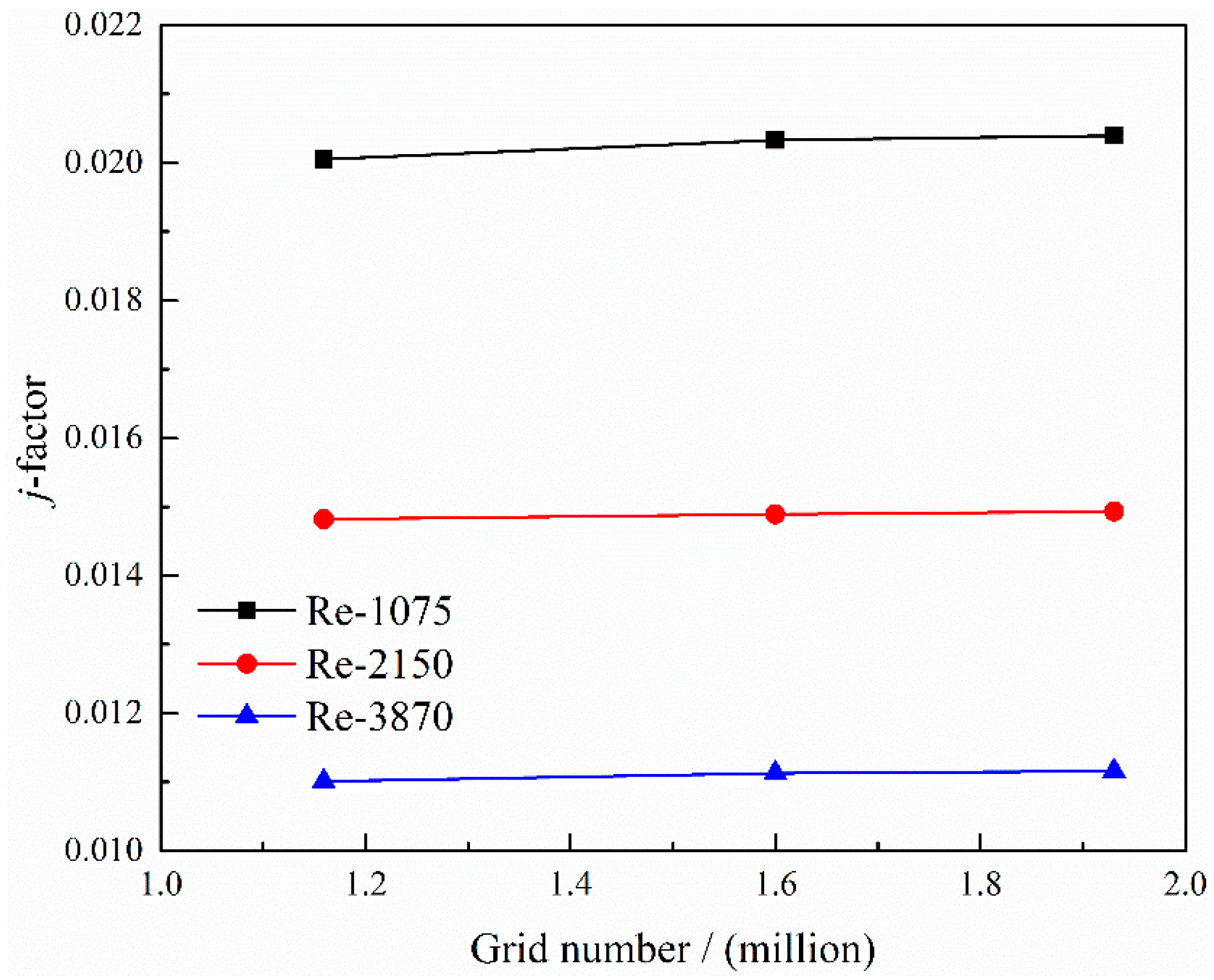
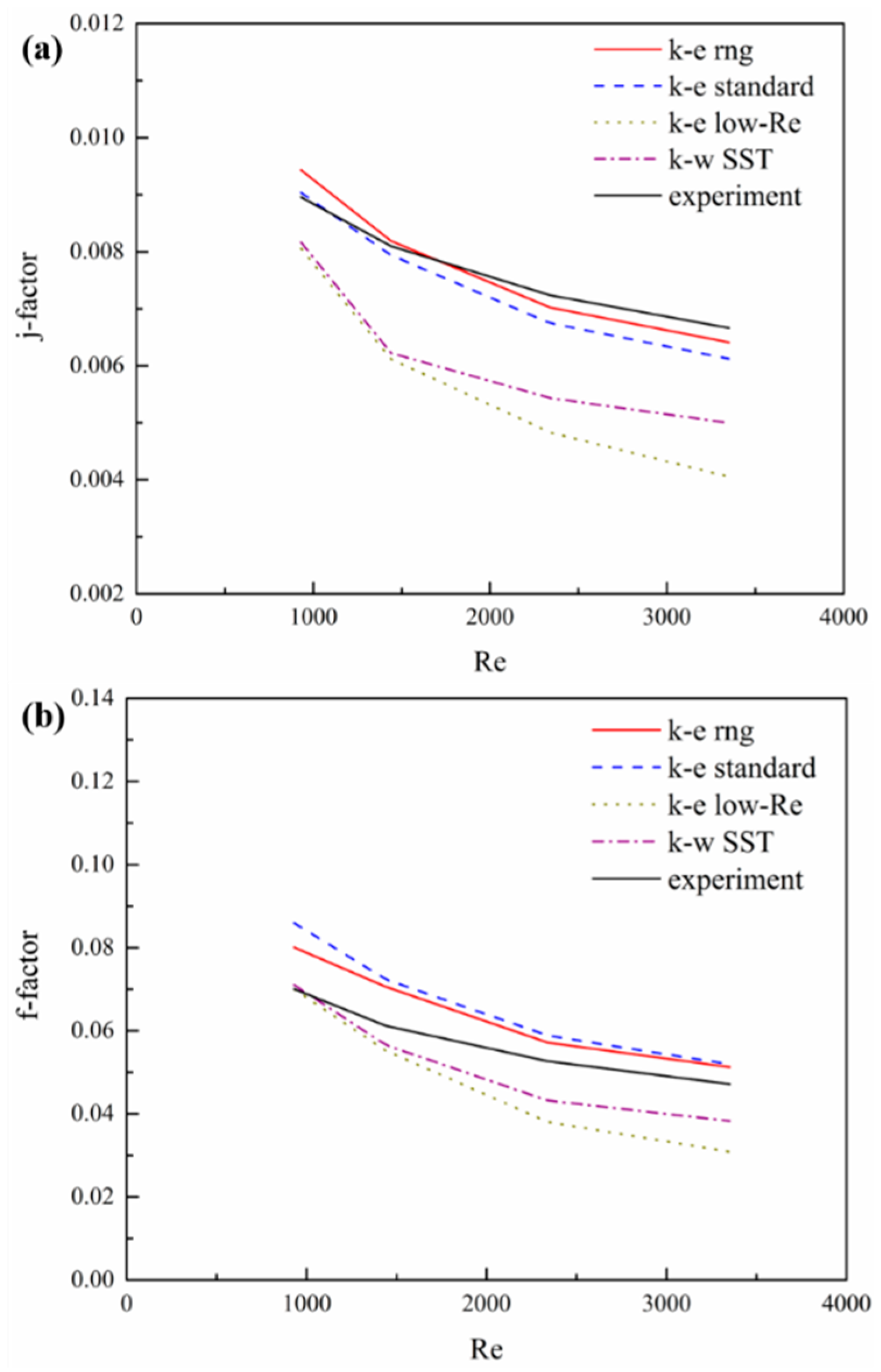
2.4. Grid Independence Tests and Verification of CFD Model

The mathematical model of the turbulent flow through the wavy fin is solved by using the commercial software FLUENT developed by ANSYS, Canonsburg, PA. The second-order upwind scheme is used to solve the momentum and energy equations. The pressure-velocity coupling flow analysis is conducted using a SIMPLE algorithm.
The computational meshes are generated by software GAMBIT 2.4.6 developed by ANSYS, Canonsburg, PA. For the region of computational domains, the structured mesh is used. For the periodic boundary, the meshes are matched by linking the periodic surfaces.
Grid independence tests are carried out before further numerical work to validate the independence of solution on the grid number. Three different grid numbers are employed to check the influence of the grid number, which includes about 1,159,000, 1,600,000, and 1,930,000 cells. Figure 3 shows the change in the j factor in accordance with the change of grid number. As shown in Figure 3, the change of j factor is less than 5% when the grid number increased from 1.159 to 1.93 million. The more gird numbers, the more computing resources and time consuming. In order to achieve a moderate accuracy and save computation time, the calculation was conducted using the corresponding mesh division method of 1.60 million grid numbers.
Figure 4 shows the comparison between the values of the (a) j and (b) f factors using different turbulent models (standard k ε model, low Re k ε model, RNG k ε model and SST model) at Re from 1000 to 4000 for the traditional wavy fin. The values of the j and f factors on the experiment are obtained using the correlations presented by Dong Junqi [23] with the same geometric parameters. The RNG k ε is selected because of the minimum error between the results and reference experimental data.
The standard k ε model assumes that the flow is completely turbulence and the influence of molecular viscosity can be ignored. It is only suitable for the simulation of complete turbulent flow. When there is strong streamline bending, whirlpool and swirling in the fluid, the accuracy of the calculation is relatively low. The low Re k ε model considers the whole boundary layer and does not depend on the wall function. Therefore, it needs more sophisticated grids and only can be used under low Reynold number conditions or in an area near the wall surface. The SST model has a strong dependence on the distance to the wall and is suitable for simulating the boundary layer and low Reynolds number flow. The RNG k ε theory not only takes into account the turbulence vortices but also provides an analytical formula for the viscous flow at low Reynolds numbers. These characteristics make the RNG k ε model more reliable and accurate than other methods, which also can be seen in Figure 4. The reason for the difference between RNG k ε model and reference experimental data could be because the data is not directly from the measurement of experiment, but by the fitting formula obtained from the experiment. On the other hand, for the wavy fin, there are subtle radian differences between the fins used in the experiment and the numerical simulation models.
Therefore, the RNG k ε model is employed in the simulation. The enhanced wall function was adopted to deal with the near wall region.

3. Results with Analysis

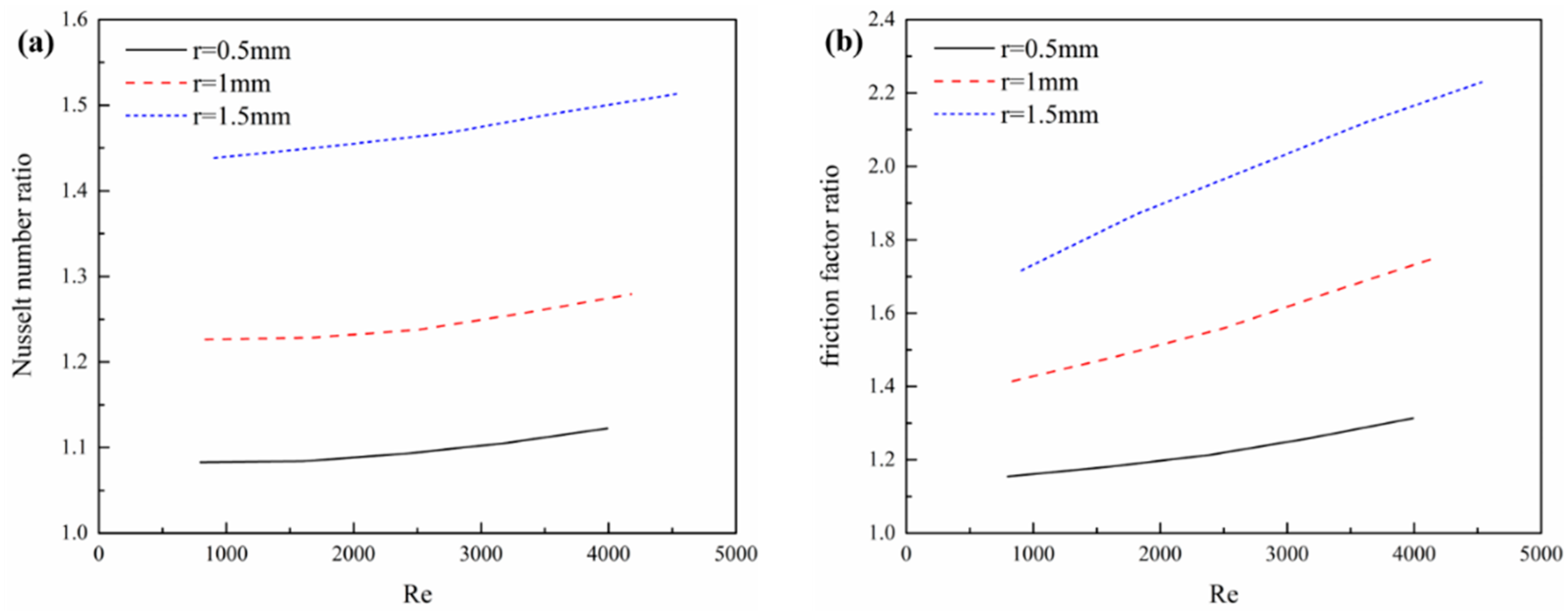
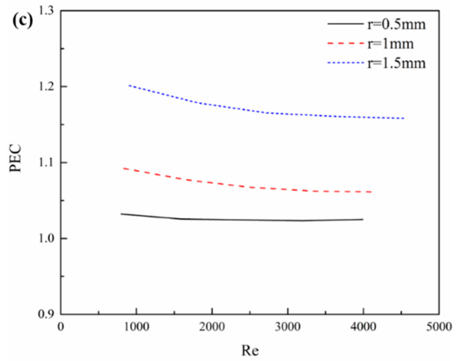
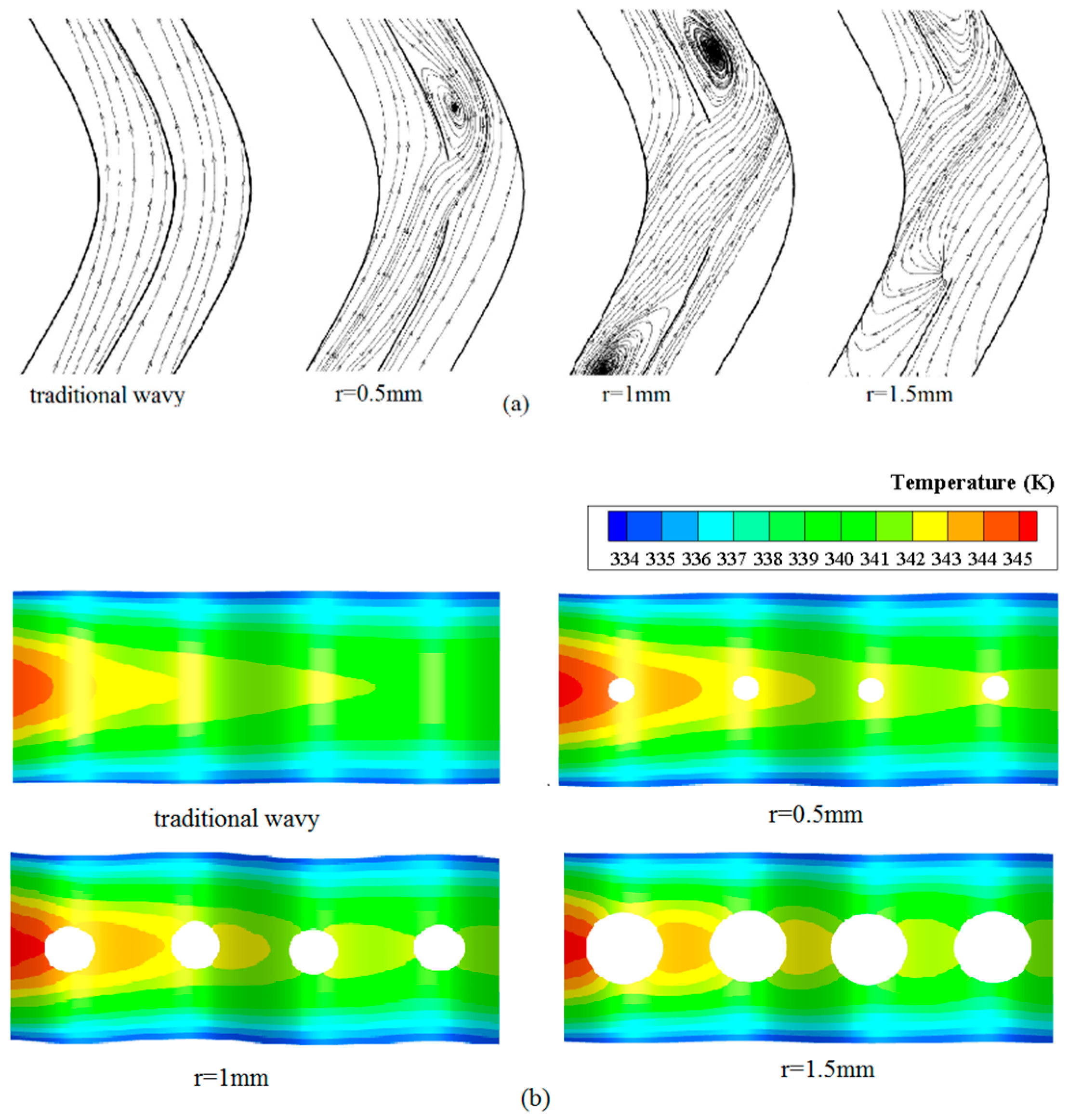
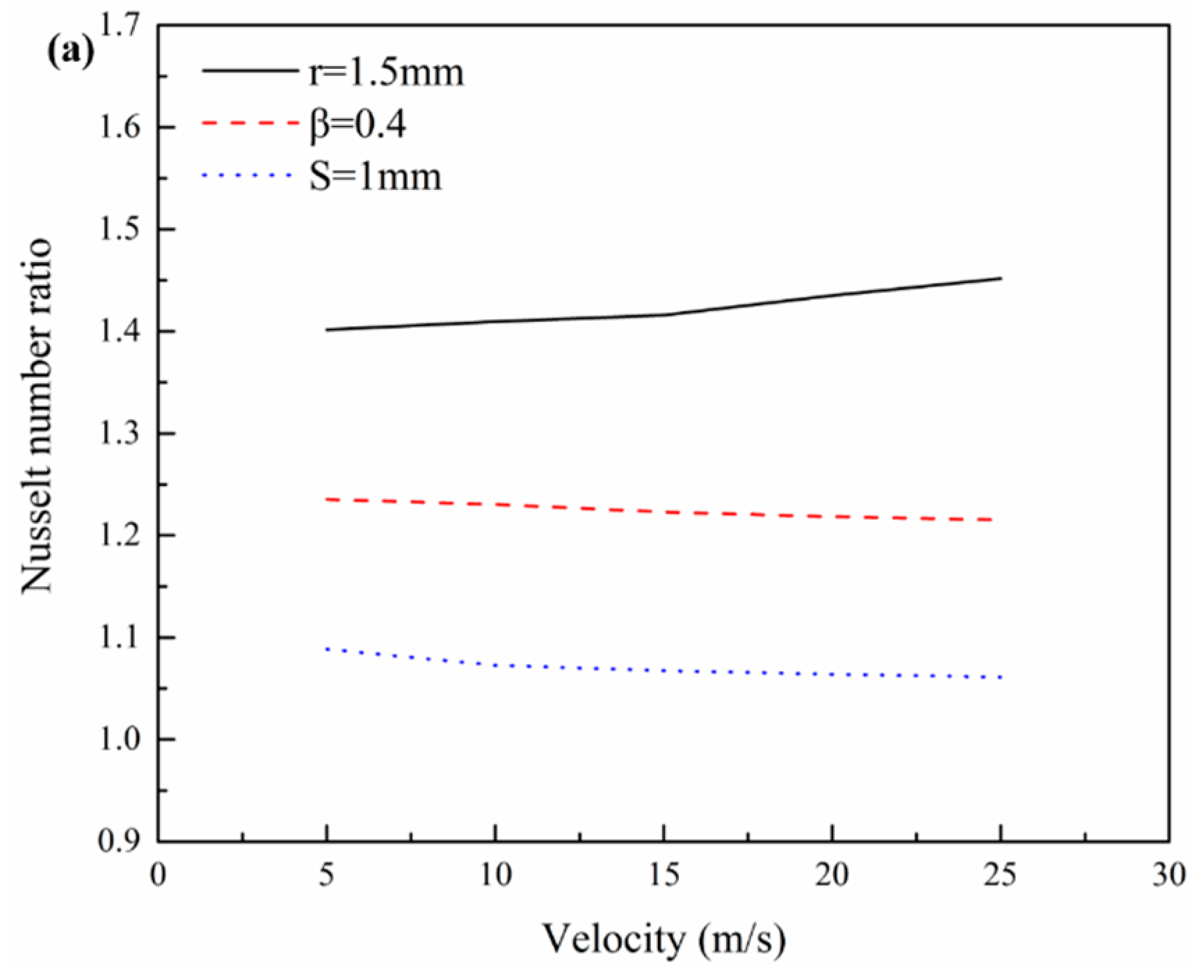
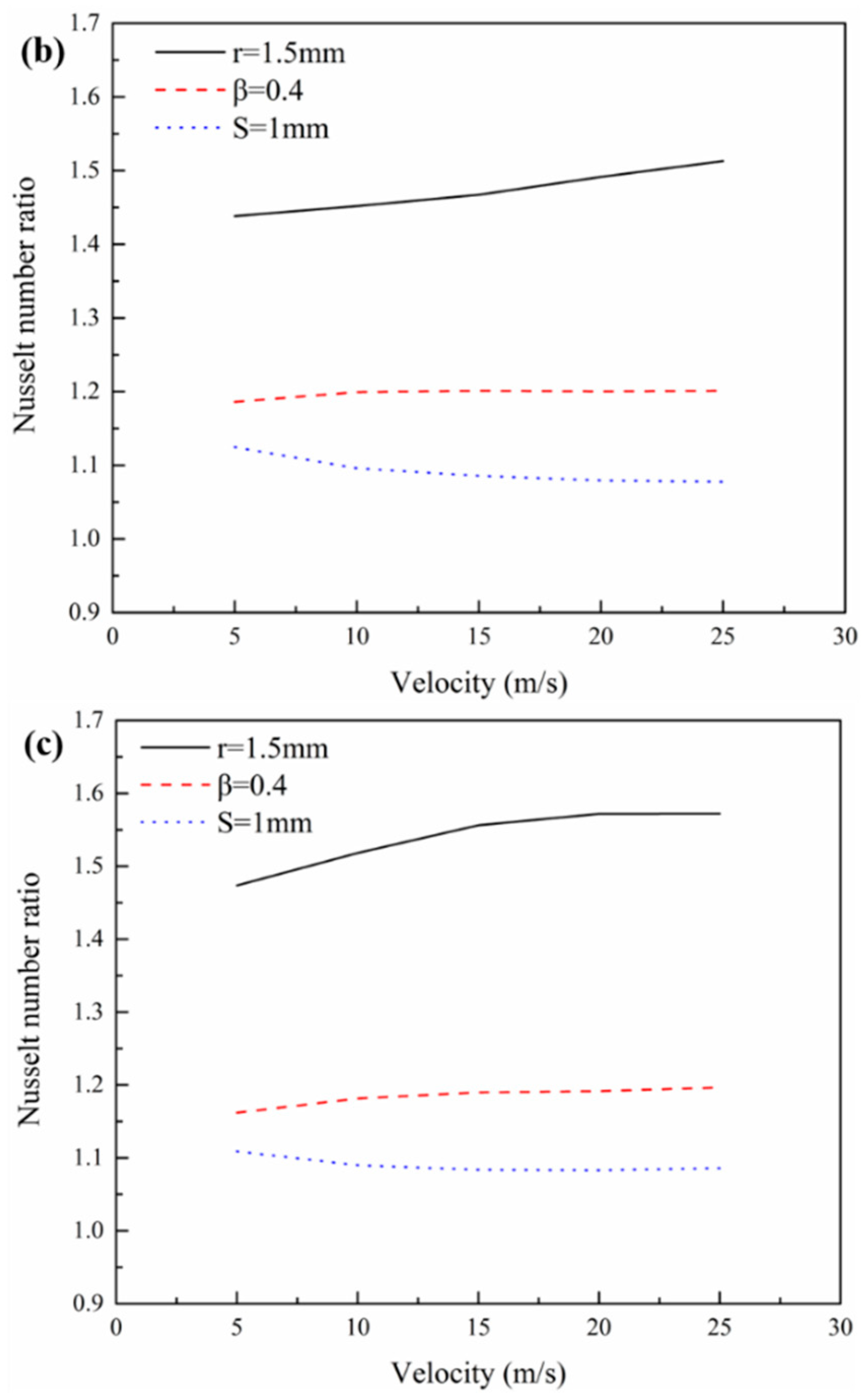
3.1. Influence of Different Perforated Radius

The relation of the Nusselt number ratio ( N u / N u b a s i c , w a v y ), friction factor ratio ( f / f b a s i c , w a v y ) and the PEC to the Reynolds number for the different perforated radius are presented in Figure 5. Figure 6 shows the change in the streamline and fin surface temperature distribution of the perforated wavy fin with the different radius. The radii of the punched holes are 0.5 mm, 1 mm, and 1.5 mm, respectively. It can be found that at the same operating condition, the perforated wavy fin with the larger punched hole has higher values of Nusselt number and friction factor. The streamline in Figure 6a shows that the enlarged hole can strengthen the flow turbulence, causing rapid mixing between the core and the fluid near the fin surface. From Figure 6b it can be seen that for wavy fin with larger punched holes the surface temperature of most regions is higher than those with smaller holes. It means that these fins had a better heat transfer. A surface having a high PEC is advantageous because it enables a heat exchanger to have good heat transfer and pressure loss performance. It is observed in Figure 5c that the PEC for the perforated wavy fin with r = 1.5 mm is obviously higher than that of the others.

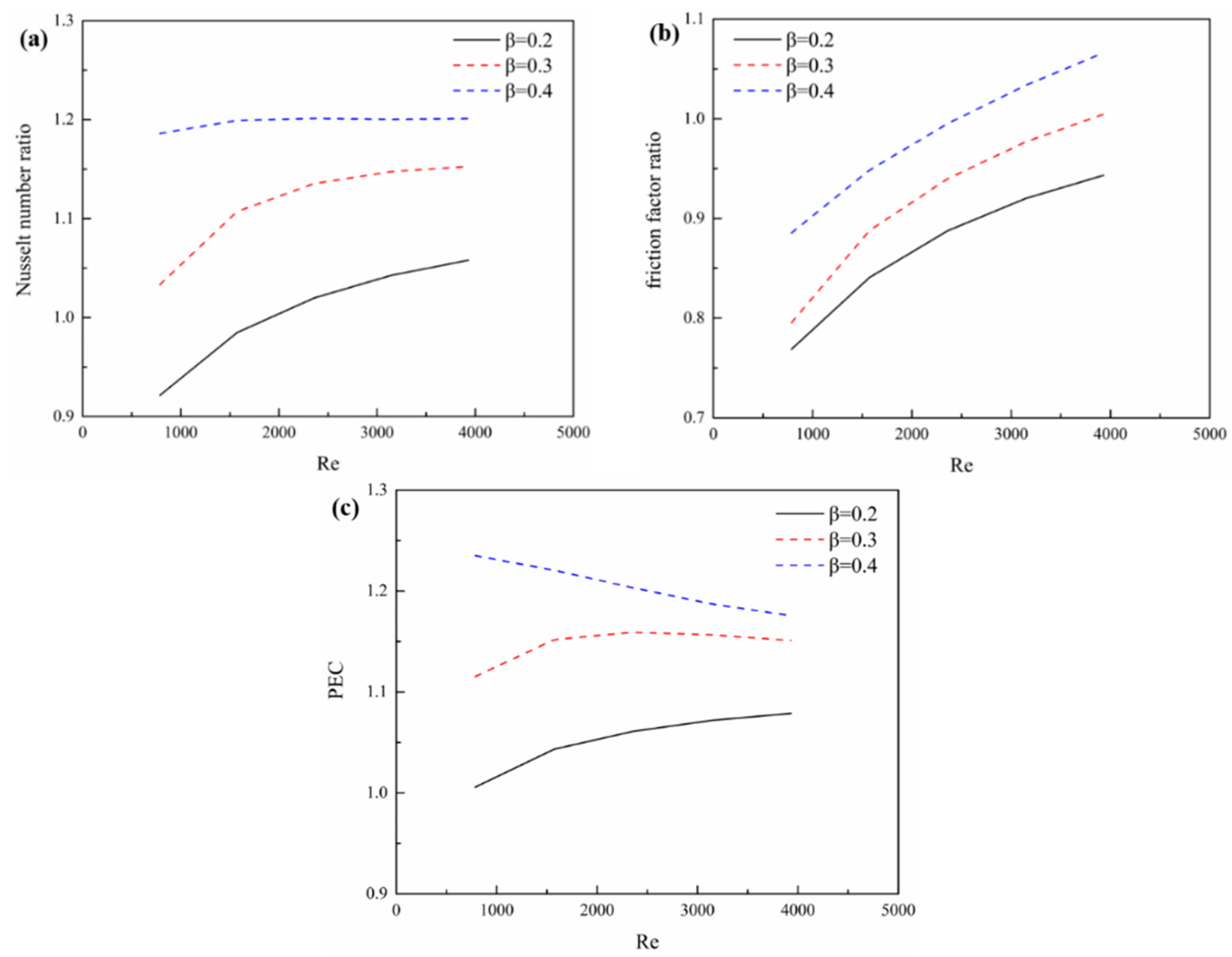
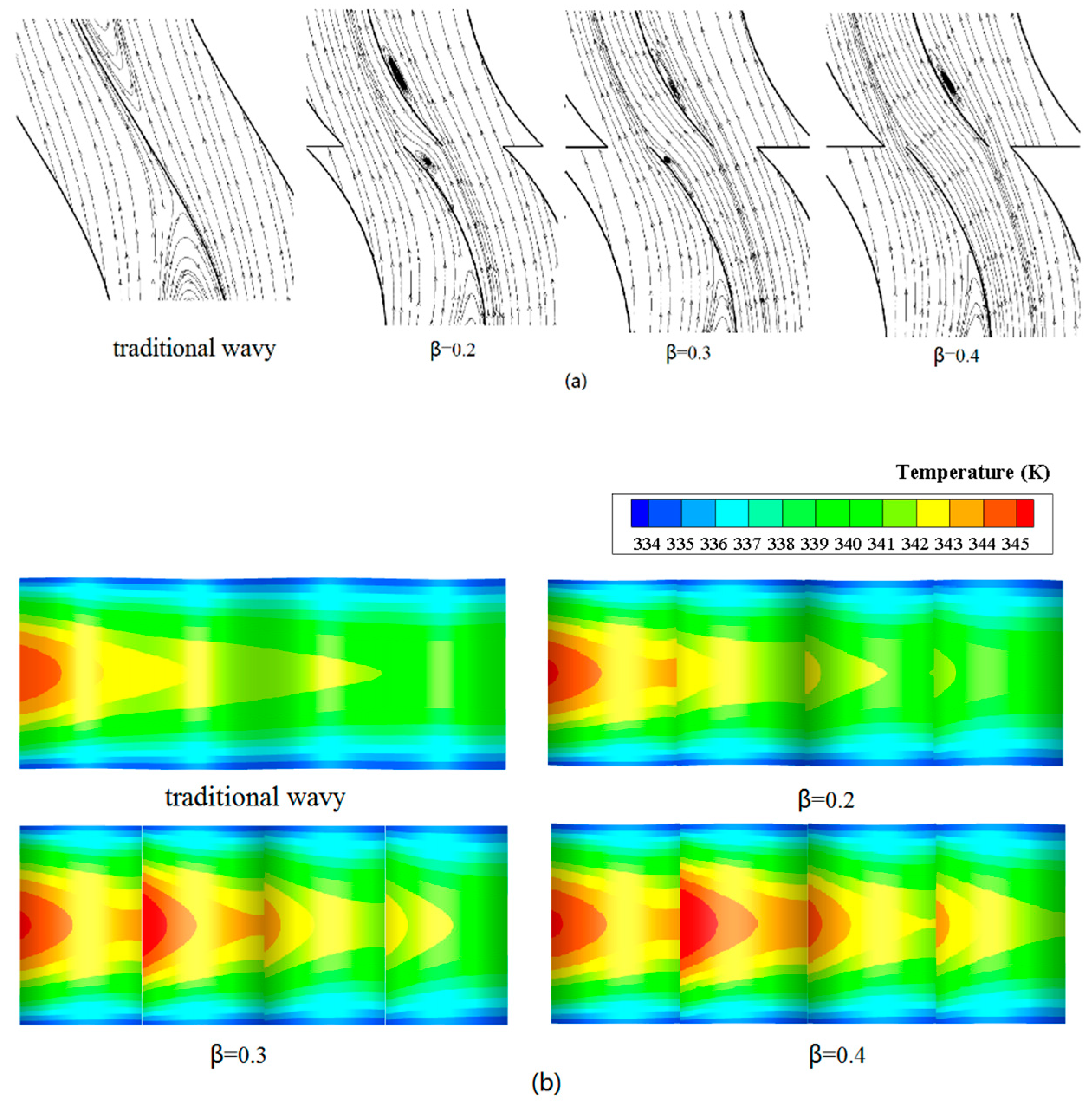
3.2. Influence of Different Staggered Ratio

Figure 7 shows, respectively, the relations between the Nusselt number ratio ( N u / N u b a s i c , w a v y ), friction factor ratio ( f / f b a s i c , w a v y ) and the PEC under different staggered ratio. Figure 8 displays the change in the streamline, the fin surface temperature distribution of the traditional wavy fin and staggered wavy fin with the different staggered ratio. The staggered ratios are 0.2, 0.3, and 0.4, respectively. In Figure 7a, it is shown that the staggered wavy fin with staggered ratio β = 0.4 has higher values of the Nusselt number ratio, which is all greater than 1 in the simulation range. It is observed in Figure 7b that friction factor ratio of staggered wavy fin increases with the increase of the Reynolds number. It is important to note that within the simulation range, the friction factor ratio is observed to be less than 1 when Re is less than 2500. Therefore, the staggered structure is good for reducing the pressure drop. From the streamline shown in Figure 8a it can be seen that the greater staggered ratio, the less flow turbulence at the staggered section. At the same time, the increase of staggered ratio decreases the swirl flow near the fin surface which is beneficial for adequate heat transfer. As shown in Figure 8b, the larger the staggered ratio, the higher the surface temperature of the fin. Figure 7c shows that the heat exchanger performance evaluation criteria for the staggered wavy fin with staggered ratio 0.4 is obvious compared to the others within the simulation range.

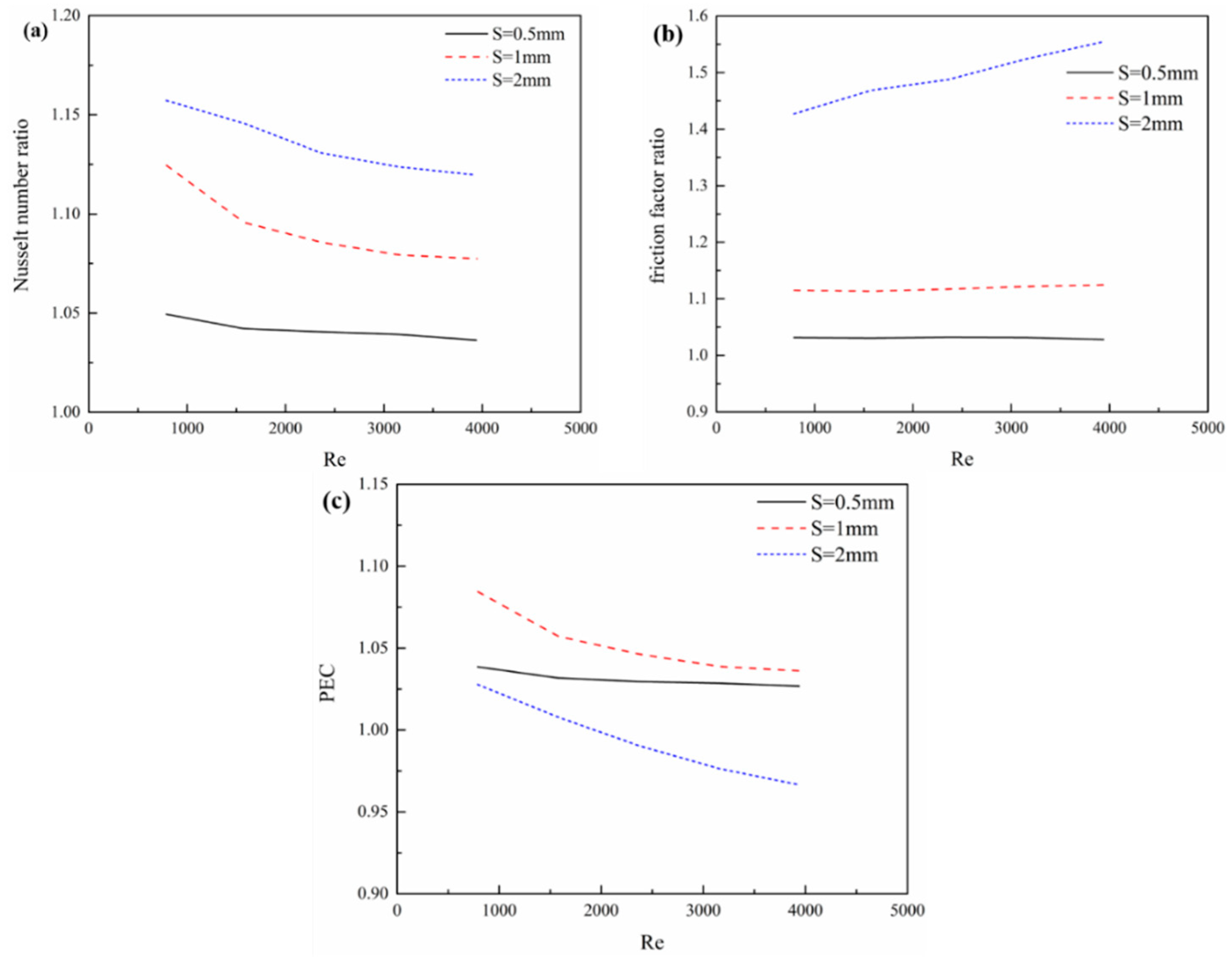
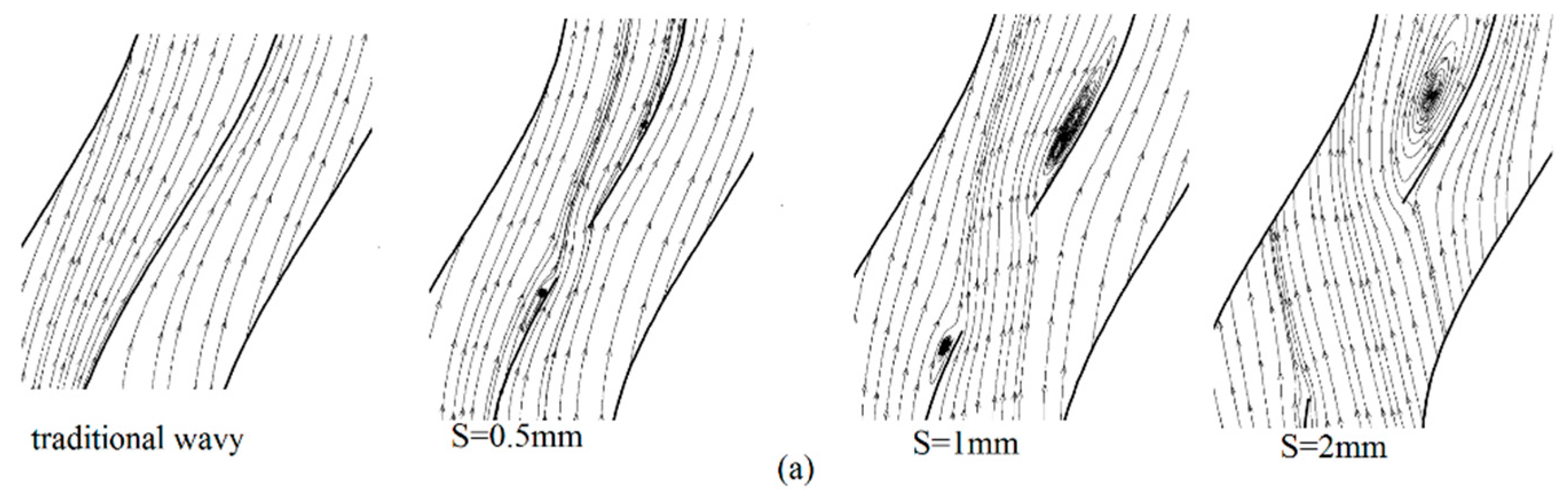
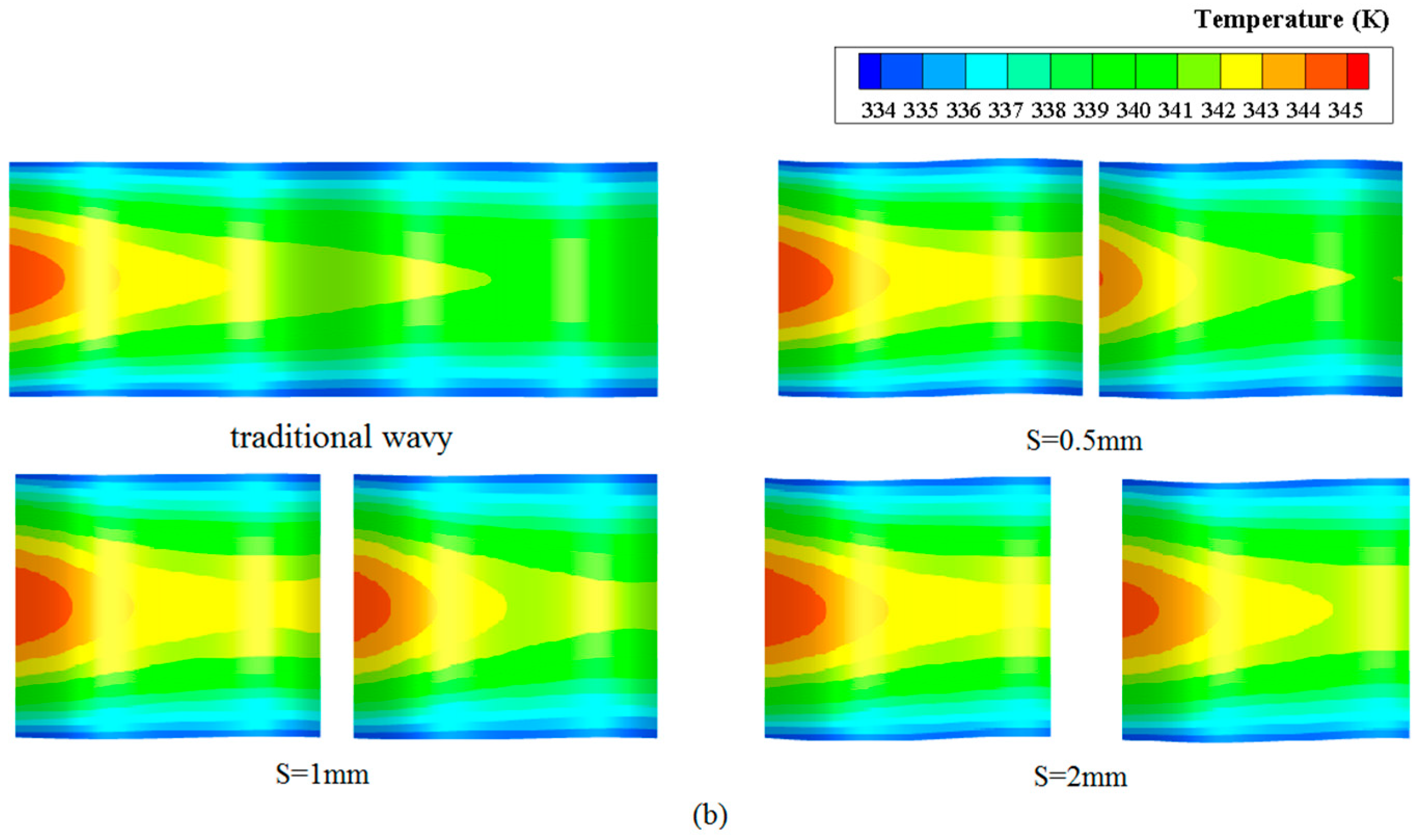
3.3. Influence of Different Breaking Distance for Discontinuous Wavy Fin

Figure 9 shows the relations between the Nusselt number ratio ( N u / N u b a s i c , w a v y ), friction factor ratio ( f / f b a s i c , w a v y ) and the PEC under different breaking distance, respectively. The change in the streamline and fin surface temperature distribution of the traditional wavy fin and discontinuous wavy fin with different breaking distance is showed in Figure 10. The distances are 0.5 mm, 1 mm, and 2 mm, respectively. It is observed that the discontinuous wavy fin with large spacing has higher values of Nusselt number and friction factor. The friction factor ratio of discontinuous wavy fin increases with the increase of Re, and the slope is maximum when the breaking distance is 2 mm. The streamline shown in Figure 10a suggests that the larger the distance between the discontinuous wavy fins, the better the mixing of fluid on both sides of the fin, thereby enhancing the heat transfer performance. At the same time, the increase of breaking distance increases the swirl flow near the fin surface. Figure 10b indicates that the temperature increases at the breaking edge of the second row, which is mainly due to the discontinuous structure interrupting the development of fluid boundary layer and thermal fluid boundary. Figure 9c shows that the heat exchanger performance evaluation criteria for the discontinuous wavy fin with 1 mm spacing is highest.

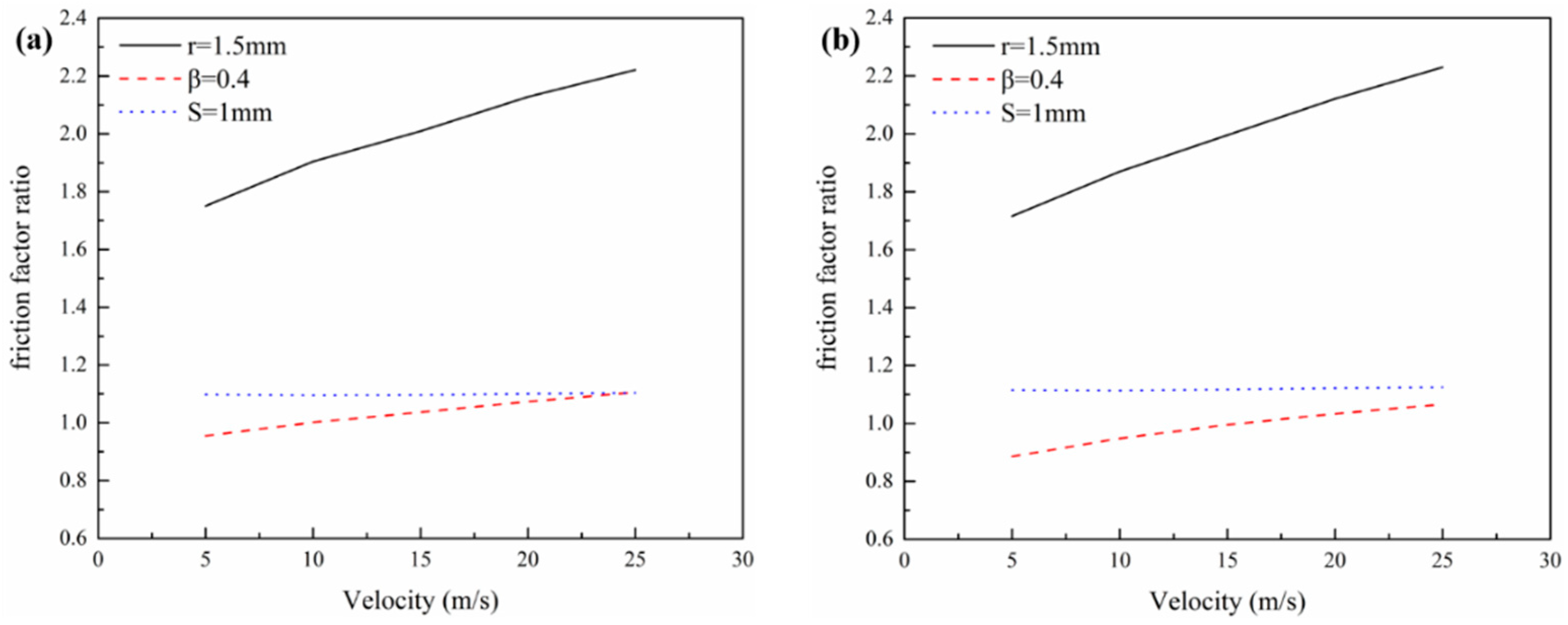
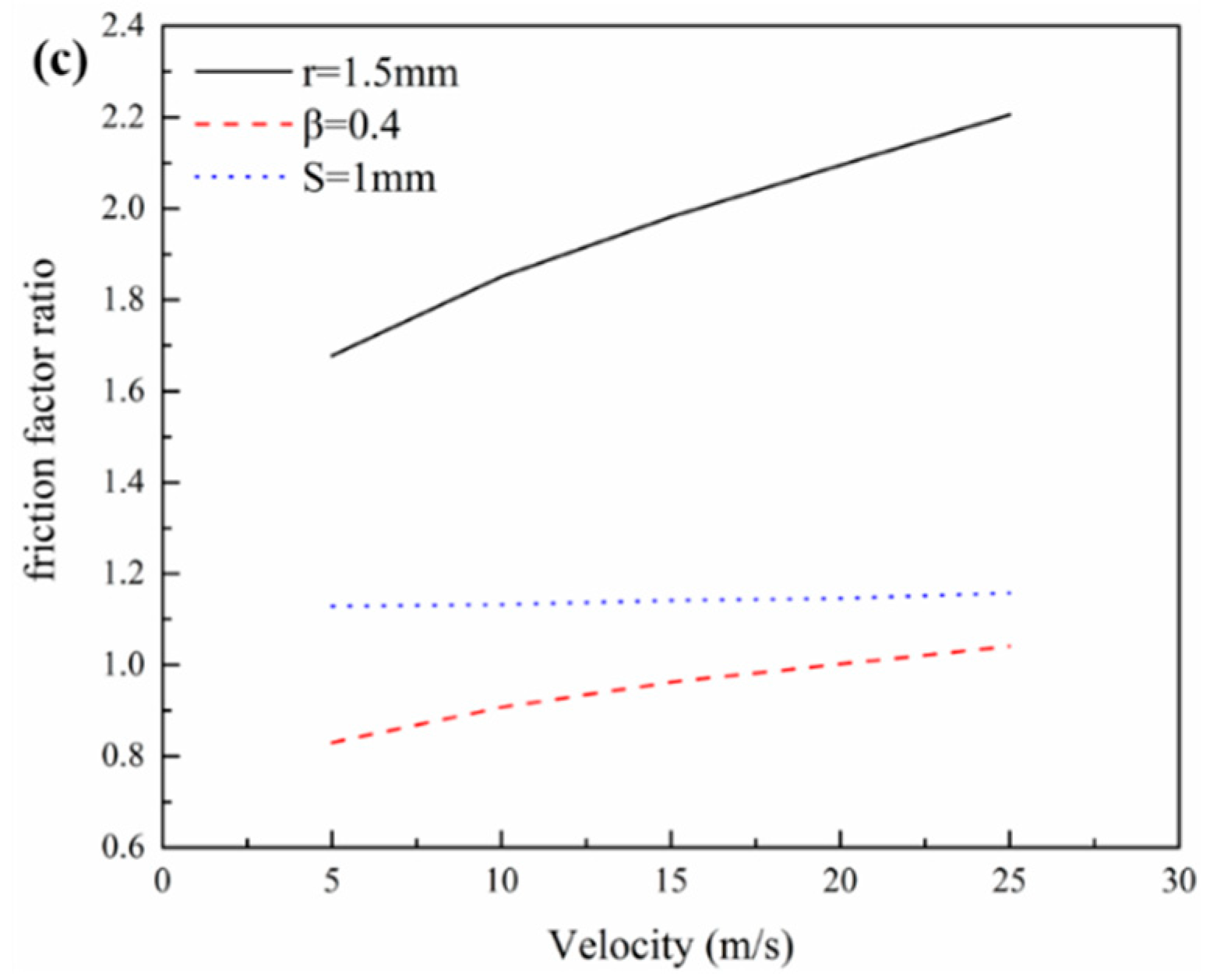
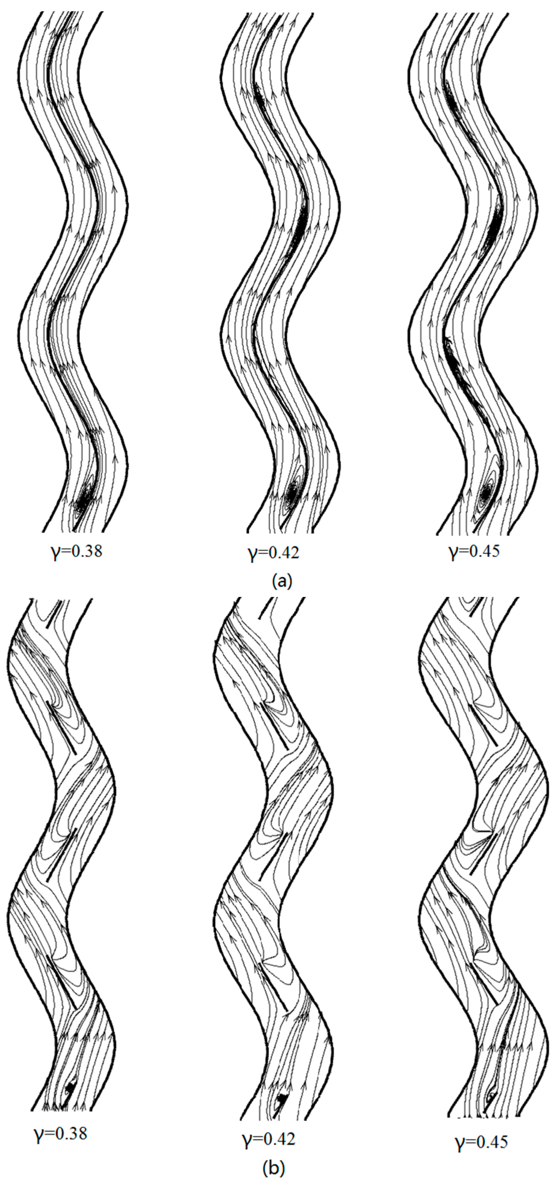
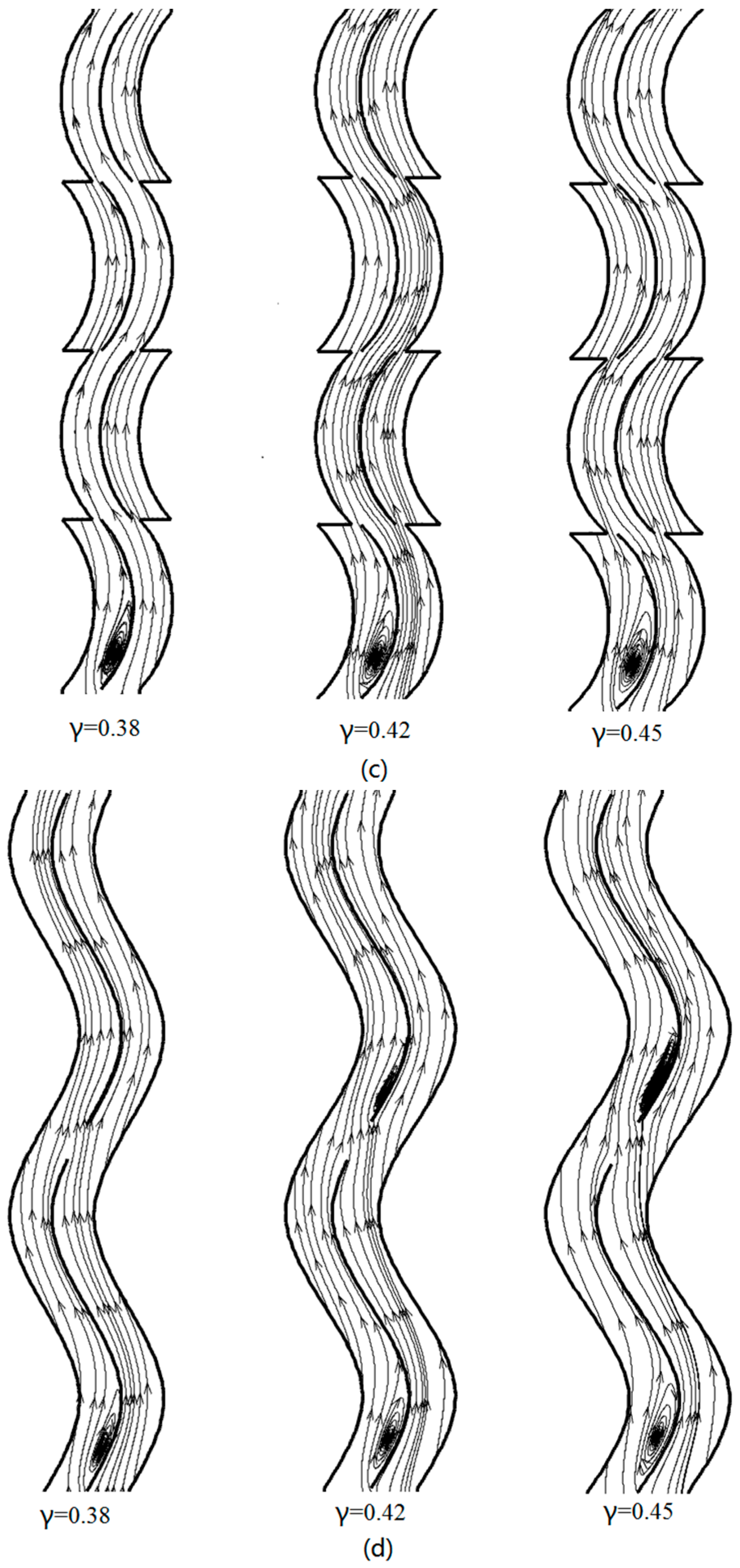
3.4. Influence of Waviness Aspect Ratio of Different Wavy Fin

According to the results of previous studies, the perforated wavy fin with R = 1.5 mm, staggered wavy fin with β = 0.4 and discontinuous wavy fin with S = 1 mm are chosen to compare with the traditional wavy fin at different waviness aspect ratio. Three values are considered (γ = 0.38, 0.42 and 0.45) to investigate the effects of the waviness aspect ratio.
The variations of the Nusselt number ratio ( N u / N u b a s i c , w a v y ) over the three new kinds of wavy fins are shown in Figure 11a–c for different waviness aspect ratio. As it can be seen, all curves have values higher than 1 which indicate that the adopted techniques are beneficial for the heat transfer. It is found that the Nusselt number ratio of the perforated wavy fin with r = 1.5 mm increases with the increasing inlet velocity, and that of the discontinuous wavy fin remains almost constant slightly bigger than 1, while the Nusselt number ratio of staggered wavy fin decreases by increasing inlet velocity. Obviously, it can be also observed that the Nusselt number ratio of the perforated wavy fin with r = 1.5 mm is the highest in all cases. At the same time, with the increase of the waviness aspect ratio, the advantage of the perforated wavy fin is more obvious while that of the other two kinds of fins are slightly declining.
It indicates that the perforation and serration techniques are beneficial for the enhancement of heat transfer at different waviness aspect ratio. It is because the perforation and serration lead to collision among streamlines and thus the enhanced flow turbulence result in greater fluid mixing. Although the heat transfer performance of the discontinuous wavy fin is not much increased, the heat transfer area is reduced which is good for saving materials.
The variations of friction factor ratio ( f / f b a s i c , w a v y ) for the three kinds of wavy fins against the inlet velocity are shown in Figure 12a–c for different waviness aspect ratios. At a given velocity, the friction factor ratio of the perforated wavy fin with r = 1.5 mm is the highest. This can be explained by strong flow fluctuation in the presence of holes on the fin surface. As can be seen, with the increase of the waviness aspect ratio, the friction factor ratio decreases. Especially for the discontinuous wavy fin, the friction factor ratio gradually becomes less than 1. The point is that the bigger waviness aspect ratio causes stronger swirl flow near the fin surface, and this trend is stronger in the traditional wavy fin than in the staggered wavy fin and discontinuous wavy fin as shown in Figure 13.
Figure 14a–c shows the variations of thermal-hydraulic performance factor over the three kinds of wavy fins for different waviness aspect ratio. The thermal-hydraulic performance factors of proposed wavy fins are all larger than 1. The change of thermal-hydraulic performance factor of the discontinuous wavy fin for different inlet velocity is small at different waviness aspect ratios. It is worth noting that with the increase of the waviness aspect ratio, the predominance of the staggered wavy fin is gradually surpassed by the perforated wavy fin. It means that using the serration technique in the smaller aspect ratio shows a considerable improvement in the thermal-hydraulic performance of the wavy fin. The maximum PEC of 1.24 is obtained for the perforated wavy fin at the largest waviness aspect ratio.

4. Conclusions

Three new kinds of wavy plate fins, namely perforated wavy fin, staggered wavy fin and discontinuous wavy fin, are proposed and investigated by numerical simulation. The current study shows that the proposed perforation, serration, and breaking technology may have advantages over the traditional wavy fins. The following results obtained can be helpful to improve air-side heat transfer performance of the plate fin heat exchanger.
  • For perforated wavy fin, the enlarged hole can strengthen the flow turbulence, causing rapid mixing between the core and the fluid near the fin surface. The bigger the holes, the better the thermal-hydraulic performance. For staggered wavy fin, the greater staggered ratio, the less flow turbulence at the staggered section. Then, the larger the staggered ratio, the better the thermal-hydraulic performance. For discontinuous wavy fin, the larger the distance between the discontinuous wavy fins, the better the mixing of fluid on both sides of the fin, thereby enhancing the heat transfer performance. At the same time, the friction factor has increased dramatically when the breaking distance is 2 mm.
  • The Nusselt number and friction factor of the perforated wavy fin are all higher than that of the traditional wavy fin. The serration technology is beneficial to reduce the friction factor compared to the traditional wavy fin. Using the serration technique in the smaller aspect ratio can obviously improve the thermal-hydraulic performance of the wavy fin.
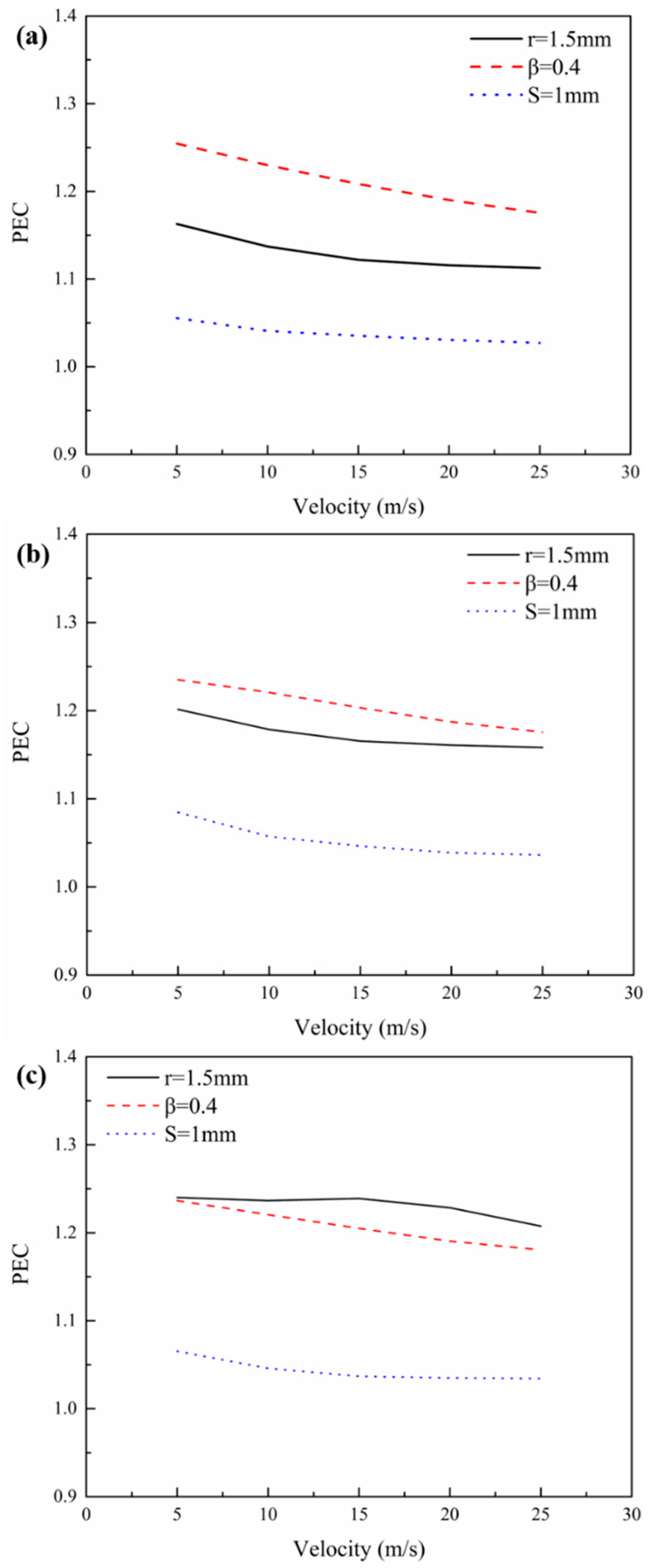
  • At a given inlet velocity, Nusselt number and the PEC for the three proposed new wavy fins are higher than that of the traditional wavy fin, and it tends to almost invariable with increasing waviness aspect ratio for the discontinuous wavy fin. At the same time, with increasing of waviness aspect ratio, the PEC for the perforated wavy fin and staggered wavy fin increases. In addition, the predominance of the staggered wavy fin is gradually surpassed by the perforated wavy fin.
  • The present research shows that the proposed heat transfer enhancement techniques all have advantages over the traditional wavy fin. Perforation is beneficial to the enhancement of the heat transfer and the improvement of the Nusselt number. Serration is beneficial to reduce the friction factor, and the breaking technique can reduce heat transfer area while enhancing heat transfer performance.

Author Contributions

Conceptualization, Z.G. and X.D.; Data curation, Y.X.; Investigation, Y.X.; Methodology, Z.G., X.D. and L.Y.; Supervision, X.D.

Acknowledgments

The financial supports for this research project from the National Natural Science Foundation of China (No. 51676069), the National Scientific and Technical Supporting Program of China (No. 2014BAA06B01) and the Fundamental Research Funds for the Central Universities of Ministry of Education of China (No. 2016XS34) are gratefully acknowledged.

Conflicts of Interest

The authors declare no conflict of interest. The founding sponsors had no role in the design of the study; in the collection, analyses, or interpretation of data; in the writing of the manuscript, and in the decision to publish the results.

Nomenclature

ATotal heat transfer area, m2
AcMinimum free flow area, m2
awave amplitude, mm
Cpspecific heat at constant pressure, kJ/(kg·K)
Dhhydraulic diameter, mm
FcStaggered spacing, mm
FhFin height, mm
FpFin pitch, mm
ffriction factor
Gmass velocity, kg/(m2·s)
hheat transfer coefficient, W/(m2·K)
jColburn factor
kThe turbulence kinetic energy
LFlow length, mm
LzWavy fin passage length, mm
lwavy length, mm
mMass flow rate, kg/s
NuNusselt number
PrPrandtl number
ppressure, Pa
PECPerformance evaluation criteria
QHeat flow, W
rPerforation radius, mm
ReReynolds number
SBreaking distance in discontinuous wavy fin, mm; mean rate of strain tensor.
Ttemperature, K
VAir inlet velocity, m/s
uiVelocity in the i direction, m/s
ujVelocity in the j direction, m/s
xiCoordinate, m
Greek Letters
βStaggered ratio
γwaviness aspect ratio
δFin thickness, mm
δijKronecker delta
ηFin efficiency
λThermal conductivity, W/(m·K)
μdynamic viscosity, Pa·s
μtturbulent viscosity, Pa·s
ρFluid density, kg/m3
τShear stress, Pa
Subscripts
ffin
ininlet
outoutlet
pplate
wwall

References

  1. Tinaut, F.V.; Melgar, A.; Ali, A.A.R. Correlations for heat transfer and flow friction characteristics of compact plate-type heat exchangers. Int. J. Heat Mass Transf. 1992, 35, 1659–1665. [Google Scholar] [CrossRef]
  2. Ismail, L.S.; Velraj, R.; Ranganayakulu, C. Studies on pumping power in terms of pressure drop and heat transfer characteristics of compact plate-fin heat exchangers&mdash—A review. Renew. Sustain. Energy Rev. 2010, 14, 478–485. [Google Scholar]
  3. Yousefi, M.; Enayatifar, R.; Darus, A.N. Optimal design of plate-fin heat exchangers by a hybrid evolutionary algorithm. Int. Commun. Heat Mass Transf. 2011, 38, 258–263. [Google Scholar] [CrossRef]
  4. T’Joen, C.; Jacobi, A.; Paepe, M.D. Flow visualisation in inclined louvered fins. Exp. Therm. Fluid Sci. 2009, 33, 664–674. [Google Scholar] [CrossRef]
  5. Vaisi, A.; Esmaeilpour, M.; Taherian, H. Experimental investigation of geometry effects on the performance of a compact louvered heat exchanger. Appl. Therm. Eng. 2011, 31, 3337–3346. [Google Scholar] [CrossRef]
  6. Kays, W.M.; London, A.L. Compact heat exchangers. J. Appl. Mech. 1984, 27, 460–470. [Google Scholar] [CrossRef]
  7. Khoshvaght-Aliabadi, M.; Hormozi, F.; Zamzamian, A. Role of channel shape on performance of plate-fin heat exchangers: Experimental assessment. Int. J. Therm. Sci. 2014, 79, 183–193. [Google Scholar] [CrossRef]
  8. Du, J.; Qian, Z.Q.; Dai, Z.Y. Experimental study and numerical simulation of flow and heat transfer performance on an offset plate-fin heat exchanger. Heat Mass Transf. 2016, 52, 1–16. [Google Scholar] [CrossRef]
  9. Dong, J.; Chen, J.; Zhang, W.; Hu, J. Experimental and numerical investigation of thermal-hydraulic performance in wavy fin-and-flat tube heat exchangers. Appl. Therm. Eng. 2010, 30, 1377–1386. [Google Scholar] [CrossRef]
  10. Joardar, A.; Jacobi, A.M. Impact of leading edge delta-wing vortex generators on the thermal performance of a flat tube, louvered-fin compact heat exchanger. Int. J. Heat Mass Transf. 2005, 48, 1480–1493. [Google Scholar] [CrossRef]
  11. Lotfi, B.; Sundén, B.; Wang, Q. An investigation of the thermo-hydraulic performance of the smooth wavy fin-and-elliptical tube heat exchangers utilizing new type vortex generators. Appl. Energy 2016, 162, 1282–1302. [Google Scholar] [CrossRef]
  12. Tang, L.H.; Chu, W.X.; Ahmed, N.; Zeng, M. A new configuration of winglet longitudinal vortex generator to enhance heat transfer in a rectangular channel. Appl. Therm. Eng. 2016, 104, 74–84. [Google Scholar] [CrossRef]
  13. Peng, H.; Xiang, L.; Li, J. Performance investigation of an innovative offset strip fin arrays in compact heat exchangers. Energy Convers. Manag. 2014, 80, 287–297. [Google Scholar] [CrossRef]
  14. Alessa, A.H.; Maqableh, A.M.; Ammourah, S. Enhancement of natural convection heat transfer from a fin by rectangular perforations with aspect ratio of two. Int. J. Phys. Sci. 2009, 4, 540–547. [Google Scholar]
  15. Shaeri, M.R.; Yaghoubi, M.; Jafarpur, K. Heat transfer analysis of lateral perforated fin heat sinks. Appl. Energy 2009, 86, 2019–2029. [Google Scholar] [CrossRef]
  16. Ridouane, E.H.; Campo, A. Heat Transfer Enhancement of Air Flowing Across Grooved Channels: Joint Effects of Channel Height and Groove Depth. J. Heat Transf. 2008, 130, 281–293. [Google Scholar] [CrossRef]
  17. Tian, L.; Liu, B.; Min, C.; Wang, J.; He, Y. Study on the effect of punched holes on flow structure and heat transfer of the plain fin with multi-row delta winglets. Heat Mass Transf. 2015, 51, 1523–1536. [Google Scholar] [CrossRef]
  18. Du, X.; Feng, L.; Yang, Y.; Yang, L. Experimental study on heat transfer enhancement of wavy finned flat tube with longitudinal vortex generators. Appl. Therm. Eng. 2013, 50, 55–62. [Google Scholar] [CrossRef]
  19. Lu, G.; Zhou, G. Numerical simulation on performances of plane and curved winglet type vortex generator pairs with punched holes. Int. J. Heat Mass Transf. 2016, 102, 679–690. [Google Scholar] [CrossRef]
  20. Jeong, C.H.; Kim, H.R.; Ha, M.Y.; Son, S.W.; Lee, J.S.; Kim, P.Y. Numerical investigation of thermal enhancement of plate fin type heat exchanger with creases and holes in construction machinery. Appl. Therm. Eng. 2014, 62, 529–544. [Google Scholar] [CrossRef]
  21. Ahn, H.S.; Lee, S.W.; Lau, S.C. Heat Transfer Enhancement for Turbulent Flow Through Blockages with Round and Elongated Holes in a Rectangular Channel. J. Heat Transf. 2007, 129, 1611–1615. [Google Scholar] [CrossRef]
  22. Kays, W.M.; London, A.L. Compact Heat Exchangers, 3rd ed.; McGraw-Hill Book Company: New York, NY, USA, 1984. [Google Scholar]
  23. Junqi, D.; Jiangping, C.; Zhijiu, C.; Yimin, Z.; Wenfeng, Z. Heat transfer and pressure drop correlations for the wavy fin and flat tube heat exchangers. Appl. Therm. Eng. 2007, 27, 2066–2073. [Google Scholar] [CrossRef]
Figure 1. The shape of (a) traditional wavy fin; (b) perforated wavy fin; (c) staggered wavy fin; (d) discontinuous wavy fin.
Energies 11 01398 g001
Figure 2. Computational domains and boundary details for the staggered wavy fin.
Energies 11 01398 g002
Figure 3. Change in the j-factor in accordance with the change of grids number.
Energies 11 01398 g003
Figure 4. Comparison between the values of the (a) j-factor and (b) f-factor using different turbulent flow models.
Energies 11 01398 g004
Figure 5. Influence of different perforated diameter on heat transfer performance with Reynolds number. (a) Nusselt number ratio; (b) friction factor ratio; (c) the performance evaluation criteria (PEC).
Energies 11 01398 g005aEnergies 11 01398 g005b
Figure 6. (a) Change in the streamline and (b) fin surface temperature distributions of the traditional wavy fin and perforated wavy fin when the radii are 0.5 mm, 1 mm and 1.5 mm.
Energies 11 01398 g006
Figure 7. Influence of different staggered ratio on heat transfer performance with Reynolds number. (a) Nusselt number ratio; (b) friction factor ratio; (c) the PEC.
Energies 11 01398 g007
Figure 8. (a) Change in the streamline and (b) fin surface temperature distribution of the traditional wavy fin and staggered wavy fin when the staggered ratios are 0.2, 0.3 and 0.4.
Energies 11 01398 g008
Figure 9. Influence of different breaking distance on heat transfer performance with Reynolds number. (a) Nusselt number ratio; (b) friction factor ratio; (c) the PEC.
Energies 11 01398 g009
Figure 10. (a) Change in the streamline and (b) fin surface temperature distribution of the traditional wavy fin and discontinuous wavy fin when the breaking distances are 0.5 mm, 1 mm and 2 mm.
Energies 11 01398 g010aEnergies 11 01398 g010b
Figure 11. Nusselt number ratio versus the inlet velocity for three kinds of wavy fin with (a) γ = 0.38; (b) γ = 0.42; (c) γ = 0.45.
Energies 11 01398 g011aEnergies 11 01398 g011b
Figure 12. Friction factor ratio versus the inlet velocity for three kinds of wavy fin with (a) γ = 0.38; (b) γ = 0.42; (c) γ = 0.45.
Energies 11 01398 g012aEnergies 11 01398 g012b
Figure 13. Change in the streamline of the (a) traditional wavy fin; (b) perforated wavy hole; (c) staggered wavy fin; and (d) discontinuous wavy fin when the waviness aspect ratio are 0.38, 0.42, and 0.45.
Energies 11 01398 g013aEnergies 11 01398 g013b
Figure 14. Thermal-hydraulic performance factor versus the inlet velocity for three kinds of wavy fin with (a) γ = 0.38; (b) γ = 0.42; (c) γ = 0.45.
Energies 11 01398 g014

