Article

A Pressurized Vitiated Co-Flow Burner and Its Preliminary Application for a Methane Lifted Flame

School of Automotive Studies, Tongji University, Shanghai 201804, China
*
Author to whom correspondence should be addressed.
Energies 2018, 11(6), 1402; https://doi.org/10.3390/en11061402
Submission received: 26 April 2018 / Revised: 29 May 2018 / Accepted: 30 May 2018 / Published: 30 May 2018

Abstract

:
A new pressurized vitiated co-flow burner (PVCB) was designed and built for the investigation of lifted flame properties and was supported by a vitiated co-flow of hot combustion products from a lean H2/air flame at a controllable pressure; its preliminary application for a methane lifted flame was tested. The distribution of the co-flow temperature, oxygen mole fraction, flow rate, and pressure of the PVCB was measured and calculated. The research results show that the co-flow temperature range is from 300 to 1300 K, the background pressure range is from 1 to 1.5 bar, the stable temperature field of the PVCB is wider, and the background pressure of the PVCB can be controlled. The simulation results show that the PVCB provides a controllable, pressurized co-flow of hot and vitiated gases, which makes it possible to investigate flame stabilization mechanisms. The PVCB has the advantages of controllable background pressure and a stable temperature field. The well-defined uniform boundary conditions and simplified flow of the PVCB simplify the establishment of a numerical model and decouple the turbulent chemical kinetics from the complex recirculating flow. It can be widely used in the research on lifted flames. A lifted flame of methane was recorded under conditions of a co-flow temperature of 1133 K and pressure from 1 to 1.043 bar. The lift-off height decreased and stabilized with the increase in the background pressure. The laminar flame speed and the autoignition delay time were tested and simulated at the same time by Chemkin; the influence of background pressure on the lift-off height, laminar flame speed, and autoignition delay were analyzed. The results show that the autoignition, as well as the flame propagation, dominated the stabilization mechanism of the lifted flame in the PVCB.

1. Introduction

A turbulent jet flame is a typical turbulent combustion mechanism in internal combustion engines and gas turbines, and it is also a fundamental topic in combustion science. When the jet velocity is sufficiently large, the flame will leave the nozzle and become a lifted flame [1,2]. The stability of turbulent jet flames is very important for turbulent combustion design, concerning its safety, efficiency, and emission control.
Once the flame is lifted, the position of the flame base is mainly determined by the balance between the jet velocity and the burning velocity, while a possible mechanism that can prompt flame stability is autoignition [3]. Finite-rate chemistry effects and highly complex interactions between chemistry and turbulence at the flame make the accurate modeling of jet flame stabilization a fairly challenging task. The investigation of turbulent jet flame stability in a hot environment and combustion products will be useful for improving combustion technology. It is very important to study the autoignition of jet fuel and the stabilization mechanism of the lifted flame in hot co-flow in order to provide an experimental database for the evaluation of combustion models and to improve the combustion reliability of gas turbines and aero engines.
The stabilization mechanisms of lifted flames have been measured by Campus Directory | University of California, Berkeley [4] and Sydney University [5] successively. Non-premixed lifted flames were generated by either hydrogen or methane central jet entraining into the hot products from a premixed H2/air combustion, which was called vitiated co-flow. The device of the experiments was named the vitiated co-flow burner (VCB). The mixing between the jet and the hot combustion products showed the turbulence–chemistry interactions during combustion, which could avoid the complicated recirculation of a computational fluid dynamics (CFD) simulation. The burner was selected as a model burner by the Turbulent Non-Premixed Flames (TNF) Workshop, which is an open and ongoing international collaboration project among experimental and computational researchers who study turbulent non-premixed and partially premixed combustion. One of its notable characteristics is the strong sensitivity of the lift-off height to the co-flow temperature.
Numerous experiments and numerical investigations of lifted flames in hot co-flow have been performed in VCBs. Dibble et al. [6,7] investigated a H2/N2 lifted flame in a VCB under co-flow equivalence ratios (ERs) of 0.20–0.27 and inferred that the propagation of a turbulent premixing flame is composed of small-scale (on the order of the flame thickness) recirculation, which makes the hot products mix with the reactants and subsequently ignite the mixture rapidly. In recent years, they examined the influence of the mixing ratio, equivalent rate, and jet rate on unsteady combustion and obtained some conclusions on the boundary conditions of the attached flame, lifted flame, unstable flame, and blow out.
The stability of a lifted flame of CH4/air under an extended co-flow temperature range was further explored at the University of Sydney [8,9,10,11]. The research showed that the CH2O peaks appear prior to the autoignition and then decay after ignition and that OH peaks appear at the moment of ignition. These peaks are stable in steady flames and can be employed to estimate the time of autoignition. The results indicated that the lifted flame stability is controlled by spontaneous fuel combustion and turbulent flame propagation at different temperature ranges. Jangi et al. [12] discovered that the strong sensitivity of the lift-off height to the small variations in the co-flow temperature (temperature of only a few degrees kelvin) in the experiments of Cabra et al. [13] cannot be explained by the edge-flame theory and the hypothesis [14,15] that the lift-off height is inversely correlated to the laminar burning velocity of the stoichiometric flame.
The VCB provides well-defined, uniform boundary conditions and simplified flow [16] for numerical simulation. Masri et al. [17] and Cao et al. [18] simulated a H2/N2 lifted flame with Fluent software by using a Reynolds-averaged Navier–Stokes (RANS)/probability density function (PDF) and two hydrogen reaction mechanisms. The simultaneous multiscalar measurements of the H2/N2 lifted flame were presented and compared with a series of numerical simulations with various combustion and turbulence models. They found that although the mixing rate is important, the flame is mainly controlled by chemical reaction kinetics, as there was no clear experimental evidence of autoignition events below the lift-off height.
Chen et al. [19,20] employed a direct numerical simulation (DNS) model and the detailed chemical reaction kinetics mechanism of hydrogen to simulate and study the H2/N2 lifted flame. They proved that autoignition is the main factor in the flame stabilization mechanism and that the HO2 radical is important for the initiating of autoignition before the flame base. The simulation provided fundamental insight into the chemistry–turbulence interactions, which was beneficial to develop and validate predictive coarse-grained models used in the design of practical combustion devices.
In our previous work [21], a VCB was built, and the characteristics of its controllable active thermo-atmosphere (CATA) were investigated. We also examined the stabilization mechanisms of diesel spray jet flames at different co-flow temperatures [22]. The results indicated that the stabilization mechanism of spray flames in the CATA varied with the co-flow temperature. The autoignition characteristics of the spray of the blended fuels varied with the co-flow temperature and revealed two different trends at different temperatures. The flame stabilization was dominated by flame spread at a higher temperature (1101 K) and was primarily controlled by the autoignition phenomenon at a lower temperature (996 K).
Because of the limitations of the VCB, these studies were performed at atmospheric pressure. North et al. [23,24] built a pressurized VCB that provided the background pressure instantly. They tested the pressure trace and the N2/H2 flow rates of the central jet and took a snapshot of the lifted N2/H2 jet flame in transient state. However, higher-temperature co-flow could not be achieved in their investigation (lower than 900 K).
In this paper, a pressurized vitiated co-flow burner (PVCB) was designed and built to study the lifted flame stabilization mechanism of central jet fuel, and a methane lifted flame under different background pressures was investigated in it. The characteristics of the pressurized CATA of the PVCB were investigated by experiments and a simulation method. In the PVCB, the lifted flame entrains vitiated hot co-flow air before it ignites, which simulates the recirculation in gas turbines.
The PVCB provides a controllable, pressurized co-flow of hot vitiated gases, which makes it possible to investigate the flame stabilization mechanisms and fuel injection in a controllable environment. Compared with a VCB, the PVCB has the advantage of controllable background pressure. In addition, a wider and more stable temperature field can be achieved. The well-defined uniform boundary conditions and simplified flow of the PVCB simplify the establishment of a numerical model and present an opportunity for investigating the chemical kinetic complications inherent when recirculation is involved, as well as the complications involved with high-Reynolds-number turbulence. The PVCB configuration is also relevant to applications; it can represent a compact and geometrically simplified version of the Alstom GT24/26 second-stage burner (Sequential EV), which also injects gas fuel (such as H2) into hot products of lean premixed H2 combustion.

2. Experimental Setup and Procedure

2.1. Structure of PVCB

Figure 1 shows the schematics and photos of the PVCB. The PVCB has the same advantages as a VCB, including a controllable thermal atmosphere and stable boundary conditions. Regarding the façade of the PVCB shown in Figure 1a, the PVCB is semi-closed with two windows on each side of the combustion chamber, through which the lifted flame can be observed and measured by optical equipment, such as a high-speed camera, LIF (laser induced fluorescence), and particle image velocimetry (PIV). The functions of the walls of the combustion chamber and the flashback chamber can be described as follows: (1) to prevent air from affecting the co-flow flame on the perforated brass plate; (2) to serve as part of the semi-closed structure to form the background pressure.
Figure 1b,d shows the schematic layout and photos of the PVCB, respectively. The burner mainly consists of a flashback chamber, flame arrestor, combustion chamber, central jet pipe, and exhaust valve. The H2/air mixture flow into the flashback chamber from the bottom and pass through the flame arrestor. A uniform distribution of the co-flow is formed in the flashback chamber; the length of the chamber is 1100 mm. The co-flow mixture passes through the perforated brass plate (Figure 1c) and flows into the combustion chamber. The H2/air mixture is ignited to form an oxygen-rich premixed co-flow flat flame. By adjusting the diameter of the outlet (0–20 mm), the background pressure can be adjusted.
The flashback chamber is located below the perforated brass plate, where H2 and air form a combustible mixture. The flame arrestor is located inside the flashback chamber, where it is filled with small glass beads with diameters of 2–3 mm. In case of backfire of the co-flow flame, the flame arrestor can prevent the flame from propagating to the co-flow inlet pipe. The flame arrestor is also beneficial to the mixing of H2 and air.
Figure 1c shows the perforated brass plate, which has 350 uniformly distributed holes. The design of the regular triangle is adopted for the layout of the holes, which means the distances between a hole and the nearest six holes are the same. The perforated brass plate also effectively prevents the co-flow flame from propagating to the flashback chamber. The diameter of the perforated brass plate is 120 mm, the thickness of the brass plate is 15 mm, the diameter of each hole is 1.6 mm, and the block area is 88% of the total plate (blockage). As long as the velocity of the air/H2 premixture in the holes is higher than the flame propagation speed of the H2/air mixture, backfire will not occur. The velocity of the air/H2 premixture in the holes is calculated by Equation (1):
V h o l e = 1 1 B V b u l k = 1 1 0.88 × 1 = 8.3   m · s 1
In the formula, Vhole is the velocity of the air/H2 premixture in the holes and Vbulk is the velocity of the air/H2 premixture in the flashback chamber; Vbulk is assumed to be 1 m·s−1, and B is the blockage (88% for our devices). The results indicate that Vhole is 8.3 m·s−1.
The flame propagation speed of the H2/air mixture is calculated under the conditions of 298 K, 1 bar, and a chemical equivalence ratio to obtain the maximum value of the H2/air premixture flame of 2.6 m·s−1; Vhole exceeds 3 times the flame propagation speed of the H2/air mixture to ensure that backfire does not occur under normal working conditions.
The central jet pipe is installed through the center of the perforated brass plate. The inner diameter of the central jet pipe is 4.6 mm, and the height from the outlet of the nozzle to the plate is 30 mm. The height of the thermocouple detection point is in accordance with the outlet of the nozzle, and the radial distance is 15 mm. The acceptable variation of the thermocouple is ±1.5 K.
The mixture of H2 and air flows into the combustion chamber of the PVCB and is ignited by a spark plug located at the edge of the perforated brass plate to form a hot co-flow. The central fuel (such as methane) is injected into the combustion chamber from the gas cylinder and autoignites to form a lifted flame. The pressure in the combustion chamber increases when the combustion product passes through the small exit of the exhaust valve. Thus, the background pressure of the co-flow in the chamber can be adjusted by changing the diameter of the outlet.

2.2. Configuration of the PVCB System

Figure 2 shows the schematic of the PVCB system, which mainly consists of the burner, the co-flow supply system, the jet fuel supply system, the cooling system, the security system, and the data acquisition (DAQ) and control system.
In the co-flow line, the hydrogen from the cylinder group and the air from the blower are mixed via the flowmeter and pressure-regulating valve. Therefore, the ER, the flowrate, and the on–off state of the co-flow can be controlled by the computer in the DAQ and control system. In the jet fuel line, the gaseous fuel from the gas cylinder (such as methane) or the liquid fuel from the tank and accumulator is injected into the combustion chamber. The injection duration and the flowrate are adjusted by the solenoid valve, and the mass flow controller is connected to the computer. The cooling system maintains the external surface of the combustion chamber at a relatively low temperature to prevent heat transfer to the flashback chamber. The safety system is applied to close the solenoid valve and cut off the supply of hydrogen when abnormal fluctuations in pressure or temperature occur. The signals from the thermocouple, pressure transducer (precision: 0.1%; measurement range: 0–2 bar), mass flow controller, and high-speed camera are received by the DAQ system and are presented on the computer monitor. The control system is based on a National Instrument DAQ module. By changing the ER, the pressure, and the mass flow rate of H2 and air in the co-flow, and by controlling the opening degree of the exhaust valve, the required co-flow temperature, background pressure, and oxygen concentration can be achieved.
The PVCB provides a controllable high-temperature zone and oxygen atmosphere, which benefits the fundamental study of the autoignition of a combustible mixture in homogeneous charge compression ignition (HCCI) combustion.
Compared with a VCB, the characteristics of PVCB are as following:
(1)
The background pressure of the PVCB is controllable.
(2)
The co-flow does not directly flow into an open space. Therefore, the temperature in the valid region is more stable, and the valid region is extended

3. Results and Discussion

3.1. Flame Structure

The co-flow of the PVCB presents an active pressurized thermo-atmosphere, which can be adjusted by changing the ER of the premixture (H2/air). Thus, the turbulent jet flame and injection under different working conditions can be investigated. The chemical equilibrium at different ERs (0.5–0.35) of the premixtures were calculated with Chemkin. The initial temperature of the premixtures was 300 K. The results of the co-flow temperature, density, and velocity corresponding to the ER are listed in Table 1. When the ER was beyond 0.35, the oxygen concentrations in the co-flow were lower than 12.7%, making it hard for the jet fuel to autoignite. Thus ERs beyond 0.35 are not listed in Table 1. The results show that with the increase in the ER, the temperature of the co-flow increased; the temperature range was from 300 to 1300 K. With the increase in the co-flow temperature, the density decreased and the velocity increased. The calculation is helpful for the controlling of working conditions and the setting of boundary conditions.
The combustion products of premixtures are listed in Table 2. The results show that with the increase in the ER, the mole percentage of O2 decreased. The oxygen mole fraction of the co-flow ranged from 12% to 21%, which could satisfy the jet fuel autoigniton. In the temperature range (700–1300 K) required for the experiment, H2 was under lean burn conditions. It inhibited the generation of nitrogen oxides and hydrocarbons, as well as other compounds, by the co-flow combustion. Thus, the co-flow was mainly dominated by H2O, N2, and O2, which could greatly simplify the data processing and analyzing. OH groups existed only at high temperatures; the OH group mol percentage increased with the increase in the co-flow temperature when the temperature exceeded 920 K. Therefore, all the OH groups measured in the low-temperature test must have been produced by the central jet, which is very helpful for data analysis.
In addition, the background pressure was 1–1.5 bar. The relative co-flow mass flow rate was 20 to 40 m3·h−1. The jet velocity and diluent gas of the co-flow can also be adjusted. The jet flame will be affected by the pressurized active thermo-atmosphere, and investigation of the co-flow of the PVCB is necessary.

3.2. Temperature Distribution

Figure 3 shows the temperature distribution in the combustion chamber when the background pressure was 1 bar and the co-flow mass flow rate was 30 m³·h−1. The average temperature was approximately 1050 K. The experimental data reveal that the temperature field was stable and the temperature at r/d (r: the radial distance; d: central nozzle inner diameter) = 20 had only a 2% difference from the central region. Compared with the measured data of the VCB by Cabra et al. [4] and Dunn et al. [25], the PVCB exhibited better temperature uniformity at different axial and radial distances, particularly in the central zone (r/d < 5), which has the most important influence on the lifted flame. The results indicate that the PVCB can be employed for quantitative research in the region of interest (ROI) range.

3.3. Calculated Velocity and Temperature Distribution

Because of the non-axisymmetric structure of the PVCB, the uniformity of the temperature field and the velocity field of the co-flow need to be validated. A solver of Fluent software was employed to simulate the velocity and temperature fields by using the RANS (Reynolds Averaged Navier-Stokes) method. Figure 4 shows the structure mesh of the PVCB; the parameters and settings of the CFD model are listed in Table 3.
Figure 5a,b shows the simulation results of the velocity and temperature fields of the PVCB at a co-flow temperature of 1133 K and a co-flow mass flow rate of 0.02 kg·s−1. Figure 5c shows the temperature distribution; as a result of the coolant of the jet pipe, the chamber wall, and the window, the temperature increased first and then decreased as r/d increased and decreased as h/d (h: lift-off height) increased when r/d > 2, which agreed with the experimental results. Because the exhaust valve exists, a back-flow occurred near the top of the burner; however, the velocity field at the central part was not interfered with. The results indicate that the PVCB provides uniform and stable temperature (the temperature in the central zone changed by less than 1%, except when h/d = 0, which did not impact the stabilization of the lifted flame) and velocity fields (the velocity vector was almost the same as the co-flow inlet direction, and there was no obvious turbulence or back-flow) in the central part (r/d < 5) of the combustion chamber.

3.4. Flame Stabilization

The working conditions of the experiment are listed in Table 4 to study the influence of background pressure on the lift-off height and stabilization of the methane lifted flame. The lift-off height and the standard deviations of the lift-off height are the main factors for flame stabilization mechanism research and model validation. The lift-off height was obtained by using visualization techniques at the lowest point at which luminosity from the flame was detected. In the experiment, the background pressure after injection was higher than the background pressure before injection because of the exothermic reaction of methane combustion.
Methane was selected as the central jet fuel instead of hydrogen because a methane flame is brighter, enabling the flame to be better captured by the high-speed camera.
Figure 6 shows the images of the lifted flame at a background pressure that ranged from 1 to 1.043 bar. The lifted flame is blue and bright at the edge and dark in the central region because the central fuel temperature was low and only partially mixed with air; thus, the edge of the central fuel autoignited first. The lift-off height evidently decreased with the increase in the background pressure; thus higher pressure values were not tested in this research.
Figure 7 shows the lift-off height of the lifted flame and the standard deviations of the lift-off height at different background pressures. When the background pressure increased from 1 to 1.043 bar, the lift-off height of the lifted flame significantly decreased. The lift-off height decreased to 40%, whereas the background pressure increased by 4.3%. With an increase in the background pressure, the standard deviation of the lift-off height decreased from 0.61 to 0.24, which indicated that the lift-off height was more stable at a higher background pressure.
Figure 8 shows that the autoignition delay of methane combustion varied with the increase in the background pressure. A Gri-Mech 3.0 reaction mechanism was employed. The autoignition delay had the same change trend as the lift-off height. However, the decrement (3.57%) was much less. This means that the background pressure affecting the lift-off height was a result of the reduction in chemical ignition. However, this was not the main reason for the high sensitivity of the lift-off height to the background pressure.
Kalghatgi [26] proposed a lift-off height correlation in terms of the maximum laminar flame speed, co-flow density, and jet properties, including velocity, viscosity, and density:
H K = 50 ( v j e t V j e t S L , m a x 2 ) ( ρ j e t ρ c o f l o w ) 1.5
In the formula, HK is the lift-off height, Vjet is the velocity of the jet fuel, and vjet is the viscosity of the jet fuel; SL is the maximum laminar flame speed, ρjet is the density of the jet fuel, and ρcoflow is the density of the co-flow. The equation means that the lift-off height of the jet turbulent flame will decrease with the increase in laminar flame speed. Figure 9 shows that the laminar flame velocity varied with background pressure calculated by the same reaction mechanism. The laminar flame velocity decreased as the background pressure increased. For a general steady flame, the flame propagation velocity is equal to that of the fuel flow. When the flame propagation speed decreases or the fuel flow rate increases, the flame tends to develop downstream. However, in this work, this was not the case with the lifted flame in the experiment.
Figure 8 and Figure 9 show that under the described conditions, the changes in autoignition delay were consistent with the lift-off height, while the flame velocity was not. In previous experiments [13,14], the autoignition delay and the flame propagation velocity were both influenced by the co-flow temperature, which resulted in the same lift-off-height change trends. In particular, the increase in the co-flow temperature led to the shortening of the autoignition delay and an increase in the flame propagation speed. Thus, whether the autoignition delay or the flame propagation speed dominated the flame stability mechanism, the results were consistent with the experimental data of the lifted height. The results in this work prove that autoignition delay, instead of flame propagation, dominates the stabilization mechanism of the lifted flame in the PVCB. Jangi et al. [12] inferred that, “The liftoff height is controlled by the autoignition process in fuel-lean gases, and not by premixed flame propagation”. The investigation in this paper showed a similar result to their work.

4. Conclusions

In this work, a pressurized vitiated co-flow burner (PVCB) was designed and built for lifted flame stabilization study, which can provide a controllable pressurized high-temperature zone and oxygen atmosphere. A preliminary application for a methane lifted flame was tested in the PVCB and a Chemkin numerical simulations with Gri-mech 3.0 were analyzed as well. The major conclusions could be drawn as follows:
(1)
A burner for studying turbulent combustion and flame stabilization was built and presented. The burner has a controllable background pressure (1–1.5 bar).
(2)
The temperature in the ROI is more stable (300–1300 K), and the ROI is extended, which provides more accurate boundary conditions.
(3)
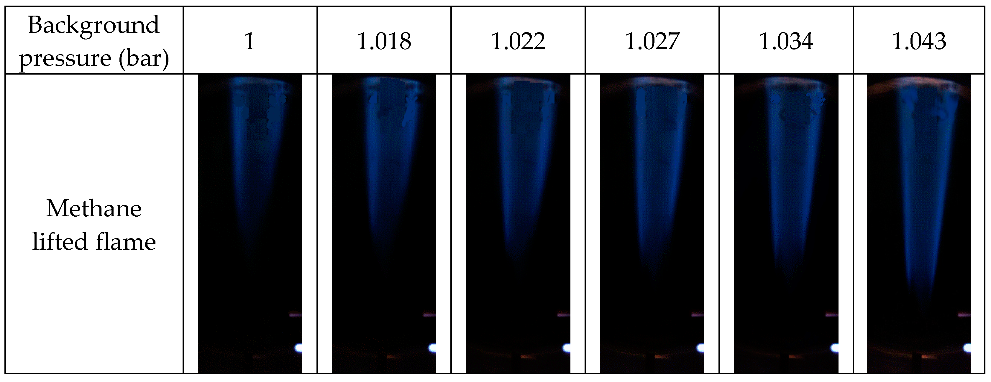
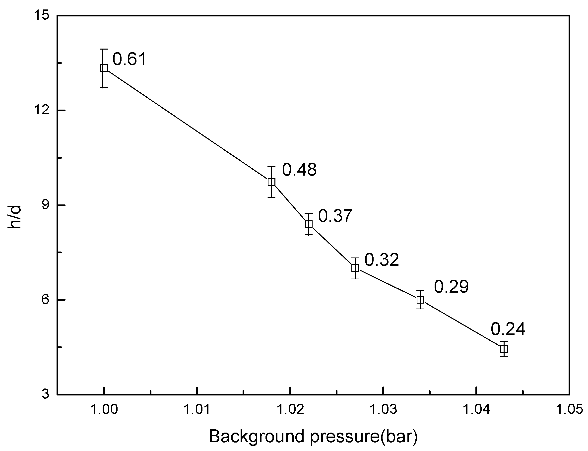
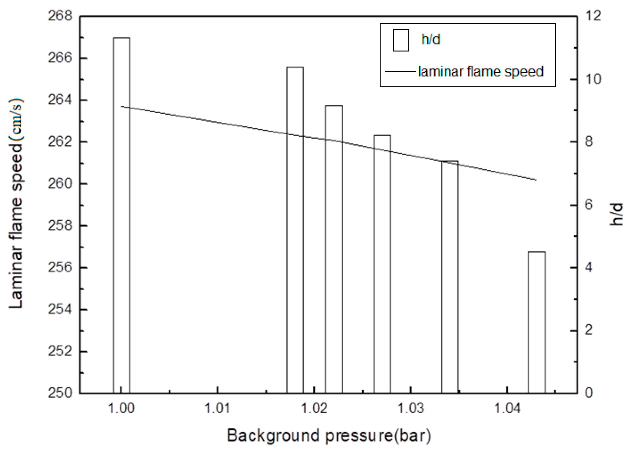
A preliminary application for a methane lifted flame was tested in the PVCB; the experimental results indicate that a lifted flame is significantly influenced by background pressure. The lift-off height decreased to 40% when the background pressure increased by 4.3%. With the increase in background pressure, the standard deviation of the lift-off height decreased, which indicates that the lift-off height is more stable at a higher background pressure.
(4)
The comparison of the experimental results and the Chemkin simulation results shows that autoignition delay dominates the stabilization mechanism of the lifted flame in the PVCB, which agrees with the work of Jangi et al. [12].

Author Contributions

The authors contributes of this research as follows: Conceptualization, Q.Q. and Q.Z.; Software, Q.Q. and W.X.; Validation, Q.Q. and P.C.; Formal Analysis, Q.Q., Q.Z. and W.X.; Investigation, Q.Q., Q.Z. and W.X.; Resources, L.L., Z.W. and J.D.; Data Curation, Q.Q.; Writing-Original Draft Preparation, Q.Q.; Writing-Review & Editing, Z.W., L.L. and J.D.; Visualization, Q.Q. and Q.Z.; Supervision, L.L. and Z.W.; Project Administration, Z.W. and J.D.; Funding Acquisition, Z.W.

Acknowledgments

This work is supported by the National Natural Science Foundation of China (91441125 and 51006075).

Conflicts of Interest

The authors declare no conflict of interest.

References

  1. Vanquickenborne, L.; Van Tiggelen, A. The stabilization mechanism of lifted diffusion flames. Combust. Flame 1966, 10, 59–69. [Google Scholar] [CrossRef]
  2. Schefer, R.W.; Goix, P.J. Mechanism of flame stabilization in turbulent, lifted-jet flames. Combust. Flame 1998, 112, 559–574. [Google Scholar] [CrossRef]
  3. Navarro-Martinez, S.; Kronenburg, A. Flame stabilization mechanisms in lifted flames. Flow Turbul. Combust. 2011, 87, 377–406. [Google Scholar] [CrossRef]
  4. Cabra, R.; Myhrvold, T.; Chen, J.Y.; Dibble, R.W.; Karpetis, A.N.; Barlow, R.S. Simultaneous laser Raman-Rayleigh-LIF measurements and numerical modeling results of a lifted turbulent H2/N2 jet flame in a vitiated coflow. Proc. Combust. Inst. 2002, 29, 1881–1888. [Google Scholar] [CrossRef]
  5. Gordon, R.L.; Masri, A.R.; Bilger, R.W. Further characterisation of lifted hydrogen and methane flames issuing into a vitiated coflow. In Proceedings of the 5th Asia-Pacific Conference on Combustion, Adelaide, Australia, 17–20 July 2005. [Google Scholar]
  6. North, A.J.; Dibble, R.W. Liftoff heights of lifted N2-in-H2 jet flames issuing into a vitiated co-flow measured using Schlieren imaging. In Proceedings of the 7th US National Technical Meeting of the Combustion Institute, Georgia Institute of Technology, Atlanta, GA, USA, 20–23 March 2011. [Google Scholar]
  7. Johannessen, B.; North, A.; Dibble, R.; Løvås, T. Experimental studies of autoignition events in unsteady hydrogen–air flames. Combust. Flame 2015, 162, 3210–3219. [Google Scholar] [CrossRef]
  8. Wu, Z.; Starner, S.H.; Bilger, R.W. Lift-off heights of turbulent H2/N2 jet flames in a vitiated co-flow. In Proceedings of the 2003 Australian Symposium on Combustion and the 8th Australian Flame Days, Melbourne, Australia, 25–27 June 2003. [Google Scholar]
  9. Wu, Z.; Masri, A.R.; Bilger, R.W. An experimental investigation of the turbulence structure of a lifted H2/N2 jet flame in a vitiated coflow. Flow Turbul. Combust. 2006, 76, 61–81. [Google Scholar] [CrossRef]
  10. Gordon, R.L.; Masri, A.R.; Mastorakos, E. Simultaneous Rayleigh temperature, OH- and CH2O-LIF imaging of methane jets in a vitiated coflow. Combust. Flame 2008, 155, 181–195. [Google Scholar] [CrossRef]
  11. Gordon, R.L.; Masri, A.R.; Mastorakos, E. Heat release rate as represented by [OH] × [CHO] and its role in autoignition. Combust. Theory Model. 2009, 13, 645–670. [Google Scholar] [CrossRef]
  12. Jangi, M.; Zhao, X.; Haworth, D.C.; Bai, X.-S. Stabilization and liftoff length of a non-premixed methane/air jet flame discharging into a high-temperature environment: An accelerated transported PDF method. Combust. Flame 2015, 162, 408–419. [Google Scholar] [CrossRef]
  13. Cabra, R.; Chen, J.Y.; Dibble, R.W.; Karpetis, A.N.; Barlow, R.S. Lifted methane–air jet flames in a vitiated co-flow. Combust. Flame 2005, 143, 491–506. [Google Scholar] [CrossRef]
  14. Upatnieks, A.; Driscoll, J.F.; Rasmussen, C.C.; Ceccio, S.L. Liftoff of turbulent jet flames—assessment of edge flame and other concepts using cinema-PIV. Combust. Flame 2004, 138, 259–272. [Google Scholar] [CrossRef]
  15. Boulanger, J.; Vervisch, L.; Reveillon, J.; Ghosal, S. Effects of heat release in laminar diffusion flames lifted on round jets. Combust. Flame 2003, 134, 355–368. [Google Scholar] [CrossRef]
  16. Mastorakos, E. Ignition of turbulent non-premixed flames. Prog. Energy Combust. Sci. 2009, 35, 57–97. [Google Scholar] [CrossRef]
  17. Masri, A.R.; Cao, R.; Pope, S.B.; Goldin, G. PDF calculations of turbulent lifted flames of H2/N2 fuel issuing into a vitiated co-flow. Combust. Theory Model. 2004, 8, 1–22. [Google Scholar] [CrossRef]
  18. Cao, P.R.; Pope, S.B.; Masri, A.R. Turbulent lifted flames in a vitiated co-flow investigated using joint PDF calculations. Combust. Flame 2005, 142, 438–453. [Google Scholar] [CrossRef]
  19. Chen, J.H.; Choudhary, A.; De Supinski, B.; DeVries, M.; Hawkes, E.R.; Klasky, S.; Liao, W.K.; Ma, K.L.; Mellor-Crummey, J.; Podhorszki, N.; et al. Terascale direct numerical simulations of turbulent combustion using S3D. Comput. Sci. Discov. 2009, 2, 015001. [Google Scholar] [CrossRef]
  20. Yoo, C.S.; Sankaran, R.; Chen, J.H. Three-dimensional direct numerical simulation of a turbulent lifted hydrogen jet flame in heated coflow: Flame stabilization and structure. J. Fluid Mech. 2009, 640, 453–481. [Google Scholar] [CrossRef]
  21. Wu, Z.; Deng, J.; Li, L.G. Study on characteristics of controllable active thermo-atmosphere of a vitiated co-flow combustor. Chin. Sci. Bull. 2005, 50, 704–707. [Google Scholar] [CrossRef]
  22. Wu, Z.; Bao, T.; Zhang, Q.; Yan, S.; Deng, J. Experimental study on spray combustion characteristics of gasoline–diesel blended fuel in a controllable active thermo-atmosphere. Fuel 2014, 135, 374–379. [Google Scholar] [CrossRef]
  23. North, A.; Magar, M.; Chen, J.Y.; Dibble, R.; Gruber, A. Effect of pressure, environment temperature, jet velocity and nitrogen dilution on the liftoff characteristics of a N2-in-H2 jet flame in a vitiated co-flow. Eurasian Chem.-Technol. J. 2014, 16, 141–148. [Google Scholar] [CrossRef]
  24. North, A.J. Experimental Investigations of Partially Premixed Hydrogen Combustion in Gas Turbine Environments. Ph.D. Thesis, The University of the California, Berkeley, CA, USA, 2013. [Google Scholar]
  25. Dunn, M.J.; Bilger, R.W.; Masri, A.R. Experimental characterisation of a vitiated co-flow piloted premixed burner. In Proceedings of the 5th Asia-Pacific Conference on Combustion, Adelaide, Australia, 17–20 July 2005; pp. 417–420. [Google Scholar]
  26. Kalghatgi, G.T. Lift-off Heights and Visible Lengths of Vertical Turbulent Jet Diffusion Flames in Still Air. Combust. Sci. Technol. 1984, 41, 17–29. [Google Scholar]
Figure 1. Schematics and photos of the pressurized vitiated co-flow burner (PVCB). (a) Façade; (b) inner structure; (c) perforated brass plane; (d) photos.
Energies 11 01402 g001
Figure 2. Experiment system of the pressurized vitiated co-flow burner (PVCB).
Energies 11 01402 g002
Figure 3. Distributions of co-flow temperature of the pressurized vitiated co-flow burner (PVCB).
Energies 11 01402 g003
Figure 4. Mesh of the pressurized vitiated co-flow burner (PVCB).
Energies 11 01402 g004
Figure 5. Velocity and temperature distributions from simulation. (a) Velocity field; (b) temperature field; (c) temperature distribution.
Energies 11 01402 g005
Figure 6. Methane lifted flame at different background pressures (1–1.043 bar).
Energies 11 01402 g006
Figure 7. Lift-off height at different background pressures.
Energies 11 01402 g007
Figure 8. Calculated autoignition delay time vs. background pressure.
Energies 11 01402 g008
Figure 9. Calculated laminar flame speed vs. background pressure.
Energies 11 01402 g009
Table 1. Chemical equilibrium calculation.
Equivalence RatioH2O2N2Temperature (K)Density (kg·m−3)Velocity (m·s−1)
Mol Ratio
0.050.1013.76470.17440.7408841.404891
0.10.2013.76631.52750.546711.911782
0.150.3013.76783.49020.4368182.402531
0.20.4013.76926.26740.3662922.876672
0.250.5013.761061.130.3170063.337119
0.30.6013.761189.4060.2804283.787171
0.350.7013.761311.710.2521554.228033
Table 2. Co-flow components’ calculation.
Equivalence RatioO2H2ON2OH
Mol Ratio
0.051.98 × 10−12.08 × 10−27.82 × 10−10.00
0.11.85 × 10−14.12 × 10−27.74 × 10−10.00
0.151.73 × 10−16.11 × 10−27.66 × 10−10.00
0.21.61 × 10−18.06 × 10−27.58 × 10−12.67 × 10⁻⁸
0.251.50 × 10−19.98 × 10−27.50 × 10−14.12 × 10⁻⁷
0.31.38 × 10−11.19 × 10−17.43 × 10−13.14 × 10⁻⁶
0.351.27 × 10−11.37 × 10−17.36 × 10−11.50 × 10⁻⁵
Table 3. Parameters and settings of the computational fluid dynamics (CFD) model.
Dimension2D
Cells45763
Nodes46642
Near-wallStandard wall functions
Co-flow inletMass-flow-inlet
OutletPressure outlet
Viscous modelRealizable k–ε
Solver typeDensity-based
Steady
Axisymmetric
Solution methodsImplicit
AUSM (Advection Upstream Splitting Method)
Local time stepCourant number = 0.5
Table 4. Boundary conditions.
Co-flow temperature (K)1133
Equivalence ratio0.32
Co-flow mass flow rate (m³·h−1)33
Jet fuel flow rate (m·s−1)37.6
Jet fuelMethane
Background pressure before injection (bar)1.0, 1.01, 1.015, 1.020, 1.025, 1.030
Background pressure after injection (bar)1.0, 1.018, 1.022, 1.027, 1.034, 1.043
Exposure time (ms)30
Frame rate (frames/s)30

