Development of Reclosing Method in a Distribution System with Distributed Generation and Battery Energy Storage System

School of IT Engineering, Yonam Institute of Technology, Jinju, Korea
Energies 2018, 11(6), 1407; https://doi.org/10.3390/en11061407
Submission received: 25 April 2018
/
Revised: 28 May 2018
/
Accepted: 29 May 2018
/
Published: 31 May 2018
(This article belongs to the Special Issue Electric Power Systems Research 2018)
Abstract
:The connection of distributed generation (DG) and a battery energy storage system (BESS) in distribution systems has recently been increasing. However, little research has been conducted on the reclosing of the distribution system when both the DG and BESS are connected. Therefore, this paper proposes a new reclosing method for a distribution system with a DG and BESS. The proposed method also has a circuit breaker (CB) installed in the distribution line. A CB close to the DG and BESS is first reclosed after a fixed dead time and, then, the fault clearance is detected using the current flowing to the fault point. Once the fault is cleared, the reclosing of the CB at the source side is attempted after completing a synchronism check. The proposed method is modeled using an electromagnetic transient program. We perform various simulations according to the capacities of the DG and the fault clearance time, and analyze the simulation results. The simulation results show that steady-state power is supplied to the load from the DG and BESS before reclosing to prevent outage, and that the reclosing is successfully performed.
1. Introduction
Globally, the grid connection of distributed generation (DG) and battery energy storage systems (BESSs) is increasing. When the DG and BESS are connected to a distribution system simultaneously, various problems might arise in terms of system operation, such as scheduling, power quality, protection, reliability, and flow. These problems have been extensively researched. Coordinated control and planning for output smoothing through DG and BESS integration have been discussed in References [1,2,3,4,5]. Energy management, scheduling, and planning in distribution systems with DG and BESSs have been discussed in References [6,7,8,9,10,11]. However, none of the previous studies have dealt with the protection issue.
The protection issue in a distribution system with DG has been extensively studied. Protection coordination strategies in the distribution system with DG were discussed in References [12,13,14,15,16,17,18]. The operation schemes of overcurrent relay considering DG were discussed in References [19,20,21,22,23]. Anti-islanding protection schemes were discussed in References [24,25]. However, these studies did not consider the existence of a BESS in the distribution system. A few protection studies have been performed in distribution system with a BESS. Reclosing methods considering a BESS used as an uninterruptible power supply were discussed in References [26,27,28]. However, these articles did not consider the existence of DG in the distribution system. Thus, the protection studies considering both DG and a BESS have not been performed so far. Thus, we study protection issues in the distribution system with both DG and a BESS, focusing on the reclosing issue in this paper.
A recloser in electric power distribution is a circuit-interrupting device equipped with a mechanism that can automatically close the breaker after it has been opened due to a fault [27]. The operation sequence of a recloser in the distribution system of the Korea Electric Power Corporation has fixed dead times of 0.5 and 15 s. Distinguishing permanent faults from temporary faults in reclosing sequences is extremely important. However, conventional reclosing adopts a fixed dead time, irrespective of whether a fault is temporary or permanent [28,29]. Only a few studies have examined reclosing in distribution systems. Adaptive reclosing algorithms in distribution systems were proposed in References [30,31,32]. However, these studies did not consider the existence of both DG and a BESS. The effects of DG on reclosing were investigated in Reference [33]. However, this paper did not propose a solution to the problem and did not consider the BESS. A novel reclosing scheme to mitigate the effects of DG on overcurrent protection in a radial distribution system was proposed in Reference [34], where the DG is disconnected from the distribution system and, hence, the reliability of the power supply cannot be maintained. An adaptive auto-reclosing scheme considering transient stability in the distribution system with the synchronous generator-based DG was proposed in Reference [35]. The BESS is connected to the distribution system through an inverter and, hence, the transient stability does not need to be considered in the distribution system with a BESS. Therefore, the proposed method in Reference [35] cannot be applied to a distribution system with both DG and a BESS.
To overcome the limitations of previous studies, this paper proposes a new reclosing method in the distribution system with both DG and a BESS. The BESS can be utilized for various purposes such as peak load shaving, frequency regulation, output smoothing of DG, and uninterruptible power supply (UPS). The BESS is considered as a UPS to maintain the power supply to the load, although the power supply from the main source is interrupted by the fault. Additionally, a circuit breaker (CB) is installed in the distribution line. The new contributions of this paper are as follows:
- (1)
- This paper proposes a new reclosing scheme in a distribution system with both DG and a BESS.
- (2)
- Several considerations on reclosing issues in the distribution system with DG and a BESS are discussed.
- (3)
- A new system configuration and fault clearance judgement method for the proposed reclosing scheme are reported. The reclosing process of two CBs in the distribution line is determined considering the fault current contribution due to the reclosing failure. To support the new contributions of the proposed method, the differences between the proposed reclosing method and the reclosing in the transmission line are discussed.
- (4)
- The proposed reclosing scheme is verified by simulating the various fault conditions using an electromagnetic transients program (EMTP) and its superiority is verified by comparing it to the conventional reclosing.
- (5)
- The advantages of the proposed method are that the steady-state power is supplied to the load from the DG and BESS before the reclosing. Therefore, the load does not experience outage and the reliability of the power supply can be improved.
The remainder of the paper is organized as follows: Section 2 discusses the effect of DG and a BESS on the reclosing of the distribution system. Section 3, based on the analysis of Section 2, proposes a new reclosing method. This section also presents the system configuration and a flowchart for the new reclosing method. Section 4 discusses the results of simulations performed using EMTP for verifying the proposed method. Section 5 concludes the study.
2. Effect of the DG and BESS on the Reclosing of the Distribution System
Figure 1 shows a distribution system model with DG and a BESS. DG is connected to Bus 3, and BESS 1 and BESS 2 are connected to Load 1 and Load 2, respectively. When a fault in Line 1 (fault 1 in Figure 1) occurs, circuit breaker 1 (CB1) in Figure 1 will be opened. An islanding operation by DG and BESS 1 and BESS 2 will occur at this time. Fault currents can be injected to Fault 1 from BESS 1, BESS 2, and DG in this case, as shown in Figure 2.
A large fault current can flow to circuit breaker 2 (CB2) through DG and BESS 2. The maloperation of CB2 can occur through the injection of a large fault current if the protective relay does not have directional characteristics. The following problems should be considered if the maloperation of CB2 occurs.
- (1)
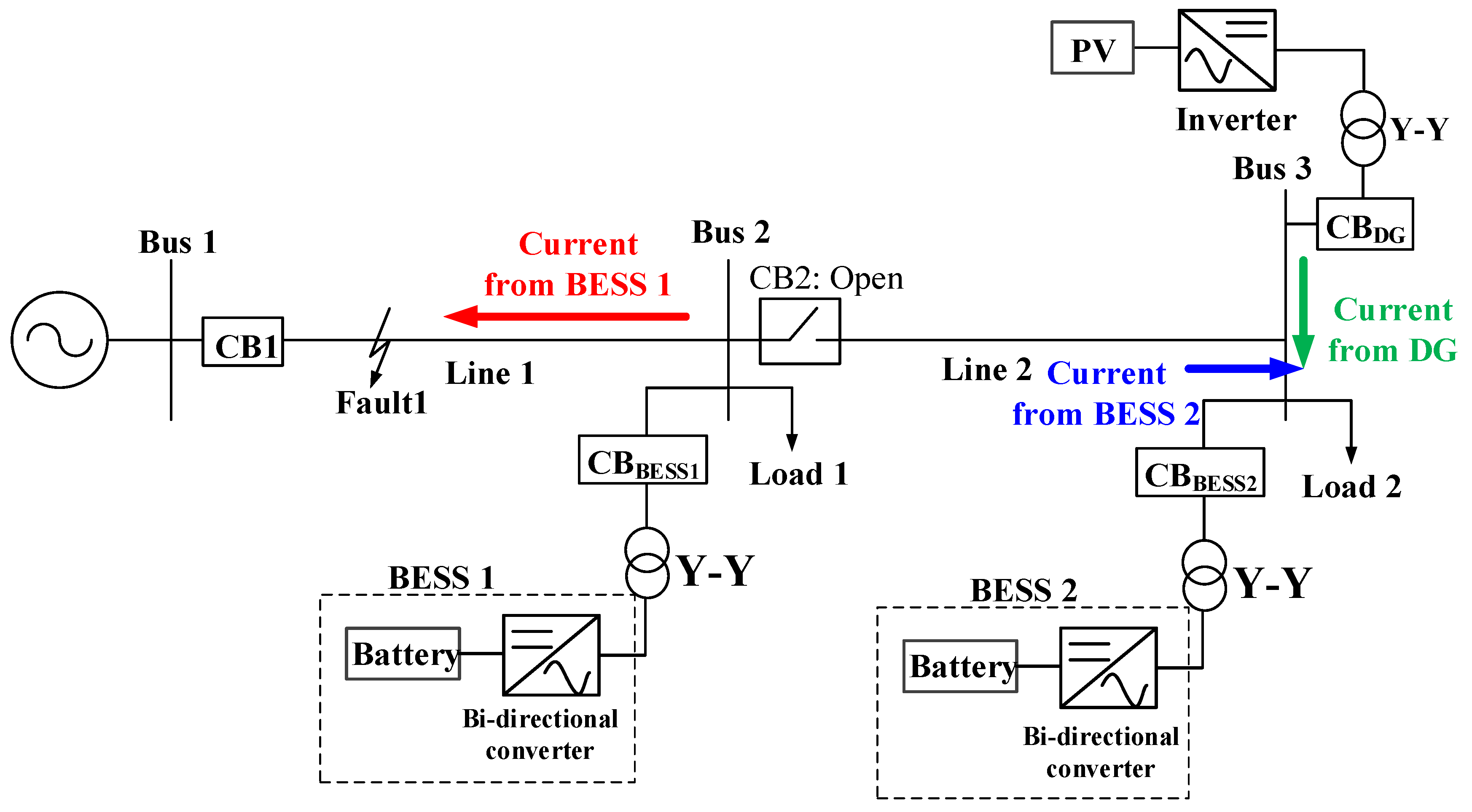
- Even if CB2 is opened, the fault current can be continuously injected from BESS 1 on fault 1, as shown in Figure 3. Therefore, after the fault occurs, a normal current can be supplied to the healthy phase of Load 1 but not to its faulty phase.
- (2)
- When reclosing is attempted, the reclosing of CB2 should also be attempted. The synchronism verification of the existence of both sources must be considered and the reclosing order of CB1 and CB2 should be established at this time.
- (3)
- Following the opening of CB2, DG and BESS 2 will supply power to Load 2. Therefore, power quality problems such as frequency, voltage, and power factor problems will occur due to the islanding operation.
When the protective relay has a directional characteristic and CB2 is not opened, the fault current can be continuously supplied to the fault location, as shown in Figure 2. Therefore, this cannot be a fundamental solution. When DG, BESS 1, and BESS 2 are disconnected from the distribution system under the fault conditions, Load 1 and Load 2 will experience an outage before reclosing. Thus, even this method cannot be a fundamental solution due to the deterioration of the reliability of the power supply.
These effects describe the problems that may occur when the faults occurred at Line 1 in Figure 3. Were the faults to occur at Line 2 in Figure 3, similar problems can also occur. The fault current can be continuously injected to the fault point if DG and BESS 2 are not separated from the distribution system. Load 2 will experience an outage if DG and BESS 2 are separated.
Therefore, this paper proposes a reclosing method to solve these problems.
3. Reclosing Method of a Distribution System Considering the DG and BESS
3.1. System Configuration for the Proposed Reclosing Method
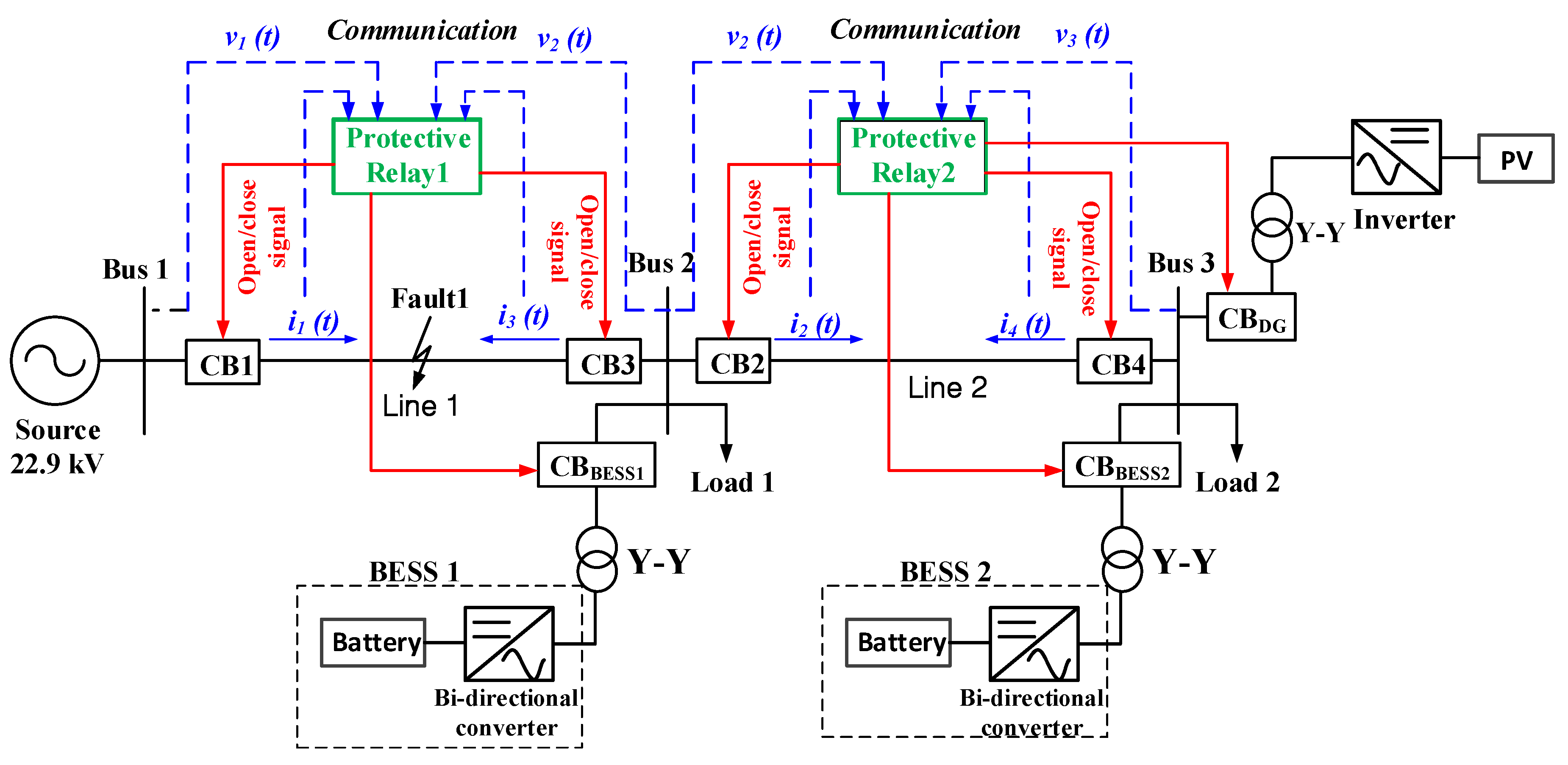
This section proposes a reclosing method for a distribution system, considering DG and a BESS. Figure 4 shows the system configuration for establishing the proposed reclosing method. No CBs are installed on either end of the line in conventional distribution systems. However, in Figure 4, circuit breaker 3 (CB3) and circuit breaker 4 (CB4) are installed additionally in Line 1 between Bus 1 and Bus 2 and in Line 2 between Bus 2 and Bus 3 to solve the above problems. The DG is connected to the distribution system through an inverter and a transformer, which is assumed to be a large-capacity photovoltaic system. BESS 1 and BESS 2 are also connected to the distribution system via the inverter and transformer. The purpose of the BESSs is to act as a UPS to maintain the power supply to the load during fault. A lithium-ion (Li-ion) battery is adopted for this study because it is sufficient for improving power system reliability and power quality. Among the available energy storage technologies, Li-ion batteries represent a suitable solution because of their features such as fast response, high-power capability, long-cycle lifetime at partial cycles, and low self-discharge rate [27]. The response time of Li-ion batteries is milliseconds, less than 1/4 cycles [36]; therefore, this paper assumes a very fast ramp rate of batteries. A communication method is required for the successful sending and receiving of open/close signals in the proposed reclosing scheme.
3.2. Flowchart of the Proposed Reclosing Method
Figure 5 shows the flowchart of the proposed reclosing method in protective relay 1 from Figure 4. First, voltages v1(t) and v2(t) of Bus 1 and Bus 2 in Figure 4 are inputted to the protective relay, which also receives currents i1(t) and i3(t), shown in Figure 4, flowing from the two CBs to the fault point. Next, the root mean squre (RMS) values of i1(t) and i3(t), as well as the magnitude, phase angle, and frequency of voltages v1(t) and v2(t), are calculated. The fault occurrence is detected if the RMS value of i1(t) increases beyond a certain value (α) and, hence, CB1 and CB3 are opened simultaneously. This will completely isolate the faulty point, so there is no possibility of CB2 maloperation due to the current supplied by DG. Moreover, there is no possibility of supplying a fault current from BESS 1. When the two breakers are opened, an islanding operation condition occurs, where the currents from DG, BESS 1, and BESS 2 are only supplied to Load 1 and Load 2. Using the DG and the two BESSs, steady-state power can be supplied during the islanding operation. The voltage can be maintained by reactive power control of the inverter connected with the DG. Usually the capacity of DG is larger than that of the BESS. The inverter control for reactive power supply, in the case of a BESS, might not be possible depending on the operation mode of the BESS because it can be used for various purposes such as peak load shaving, frequency regulation, and uninterruptible power supply. However, because the power supply by the DG is usually possible, the inverter control for reactive power supply is also possible. Thus, the reactive power control using the inverter connected with the DG has more advantages than that using the inverter connected with a BESS to maintain the voltage. During the islanding operation, if the voltage is lower than normal range, the inductive reactive power will be supplied by the inverter. When the voltage is higher than normal range, the capacitive reactive power will be supplied by the inverter. When the voltage and frequency are not maintained within a normal range even when using the reactive power control by the inverter, the DG and BESS will be disconnected from the distribution system. In Figure 5, 20.9 kV and 23.8 kV are the lower and upper limits for the normal range of voltage in the distribution system of Korea and 59.8 Hz and 60.2 Hz are the lower and upper limits for the normal range of frequency in the distribution system of Korea.
Generally, the fault current supplied from the BESS and DG connected to the system through an inverter is smaller than that supplied from the main power [26]. Therefore, if the fault is not removed, the current flowing to the fault point is also smaller. Furthermore, after the fixed dead time set for reclosing has elapsed (first: 0.5 s, second: 15 s), the reclosing of CB3 is first attempted. There will be a certain amount of fault current flowing in the fault point in the faulty phase if the fault is not removed, as shown in Figure 6. However, if the fault is removed, no current will flow in the fault point in all three phases, as shown in Figure 7. Therefore, if the RMS value of i3(t) flowing in the fault point, i.e., I3RMS, is smaller than the predetermined value (β), the fault can be judged to be removed. When the fault is removed, a synchronism verification of Bus 1 and Bus 2 is performed, for which the differences in voltage magnitudes, phase angles, and frequencies of Bus 1 and Bus 2 voltages are calculated. Providing that this value is less than a certain value, the synchronism check is completed and the reclosing of CB1 is attempted. The threshold values, γfrequency, γvoltage, and γangle, for the synchronism check are independent of the system conditions. During the simulation, the values of γfrequency, γvoltage, and γangle are set to 0.2 Hz, 5%, and 15°, respectively. These values are determined based on Reference [37]. CB1 is closed after the synchronism check is complete. Assuming the fault is not removed even after two times of reclosing after the fixed dead time elapses, it can be judged as a permanent fault and CB1 and CB3 will be locked out.
When DG and the BESS are disconnected from the distribution system (CBBESS1,2: open, CBDG: open) because the voltage and frequency are not maintained within the normal range during the reclosing process, they should be reconnected after successful reclosing. This can be done after confirming that the voltage and frequency have returned to within the normal range.
Figure 5 describes the protective relay 1 installed in Line 1 between Bus 1 and Bus 2. The same configuration and method can be applied to the protective relay 2 installed in Line 2 between Bus 2 and Bus 3. CB4 can be installed in Line 2 in this case. The algorithm in Figure 5 can be applied to the protective relay 2. Inputs from the CB1 side of Line 1, i1(t) and v1(t), are changed to the inputs from the CB2 side of Line 2, i2(t) and v2(t), respectively. Additionally, inputs from the CB3 side of Line 1, i3(t) and v2(t), are change to the inputs from the CB4 side of Line 2, i4(t) and v3(t), respectively. Subsequent to calculating the related items, the reclosing operations of CB2 and CB4 are performed. Figure 5 shows that the operations of CB1 and CB3 change the operations of CB2 and CB4, respectively. Therefore, CB4 is first reclosed, and then the method for the fault clearance judgment method can be similarly applied; the fault clearance is determined by the magnitude of I4RMS. Following that, the reclosing of CB2 is performed after the synchronism check.
The reclosing method proposed in this paper may be seen as similar to the reclosing of a transmission line. However, the differences between two methods are as follows.
- (1)
- Regarding the reclosing of a transmission line, the reclosing at the leading station close to the main power is first performed, and then the reclosing at the following station is carried out. However, in the proposed method, the reclosing of the CB close to the DG and the BESS and not at the main source is first performed to prevent the injection of the high fault current to the fault point when the reclosing fails.
- (2)
- Concerning the reclosing of a transmission line, whether the fault is removed is determined by judging whether the magnitude of the fault current is larger than the normal current after the reclosing. However, in the case of the proposed method, whether the fault is removed is determined by judging whether the current injected from the DG and BESS side is smaller than the predetermined value (β).
- (3)
- Pertaining to the reclosing of a transmission line, there is no load on the Bus. However, in the case of the proposed method, it is possible to increase the reliability of the power supply by not separating the DG and BESS because there is a Load. To achieve this, the DG has the reactive power control function to maintain the bus voltage within the normal range.
- (4)
- In the case of the reclosing of a transmission line, only the operations of the CBs at both ends are controlled. However, in the proposed method, if the voltage and frequency are not maintained within the normal range after the CBs are opened, the operations of the CBs connected with the DG and the BESS as well as the operations of the CBs at both ends are controlled.
4. Simulation and Discussion
4.1. System Model and Simulation Conditions
The distribution system model for verifying the proposed reclosing algorithm is shown in Figure 4. The capacity and power factor of Load 1 and Load 2 are 3000 kVA and 0.9, respectively. The length of both Line 1 and Line 2 is 5 km and the type of line is an aluminum conductor steel-reinforced 95 mm2. The discharge capacities of BESS 1 and BESS 2 during the fault are 2000 kW. The type of DG is a photovoltaic system, and hence, it is connected to the distribution system through the inverter. The whole system, including the distribution system, proposed reclosing method, DG, and BESS, is modeled by EMTP. The communication method is modeled using EMTP/MODELS [26,27,28,38]. A reactive control function is also modeled in the modeling of the inverter connected with the DG [39].
The simulations according to the DG capacities are performed to verify the maintenance of steady-state voltage and frequency at the point of common coupling (PCC). In Table 1, Case 1 and Case 4 are cases in which the sum of the DG capacity and the BESS discharge capacity is smaller than the load capacities. Case 2 is the case in which the sum of the DG capacity and the BESS discharge capacity is equal to the load capacities. Case 3 and Case 5 are the cases in which the sum of the DG capacity and the BESS discharge capacity is greater than the load capacities.
The fault occurs in Line 1 of Figure 4. The fault location is 50%, which means that it is 2.5 km away from Bus 1. Additionally, the fault type is a single line-to-ground fault, with a fault resistance of 1 Ω. The transient and permanent faults are simulated. In Table 1, Case 1, Case 2, and Case 3 are cases used to verify the first reclosing attempt. Case 4 is the case used to verify the second reclosing attempt, while Case 5 is the case that verifies a permanent fault.
To demonstrate the superiority of the proposed reclosing method, the simulation results are compared with those of the conventional reclosing scheme. When using the conventional reclosing scheme, the BESS and DG are disconnected from the distribution system and reclosing is performed after fixed dead times of 0.5 s and 15 s. During the simulations of Case 4 and Case 5, the fixed dead time for the second reclosing attempt is changed to 0.5 s rather than 15 s for the convenience of the simulations.
4.2. Simulation Results and Discussion
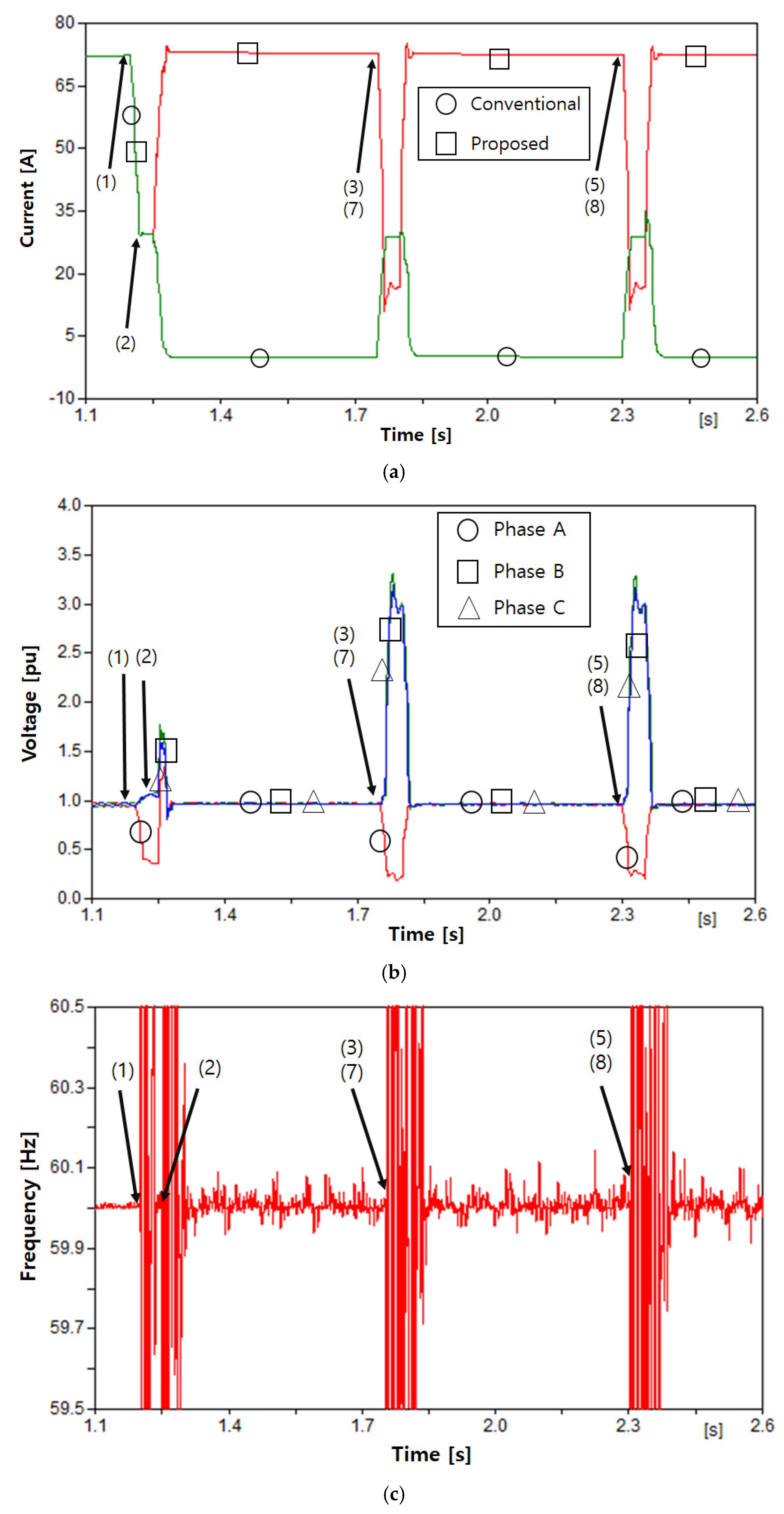
The current of phase A flowing to Load 2 and the voltage and frequency at Bus 3 are presented for each of the above cases. The current and voltage are presented as an RMS value. The meaning of the numbers in each graph is as follows.
- (1)
- Fault occurrence
- (2)
- Opening of CB1 and CB3
- (3)
- First reclosing of CB3
- (4)
- (First reclosing of CB1
- (5)
- Second reclosing of CB3
- (6)
- Second reclosing of CB1
- (7)
- First reclosing of CB1 at conventional reclosing
- (8)
- Second reclosing of CB1 at conventional reclosing
4.2.1. Case 1
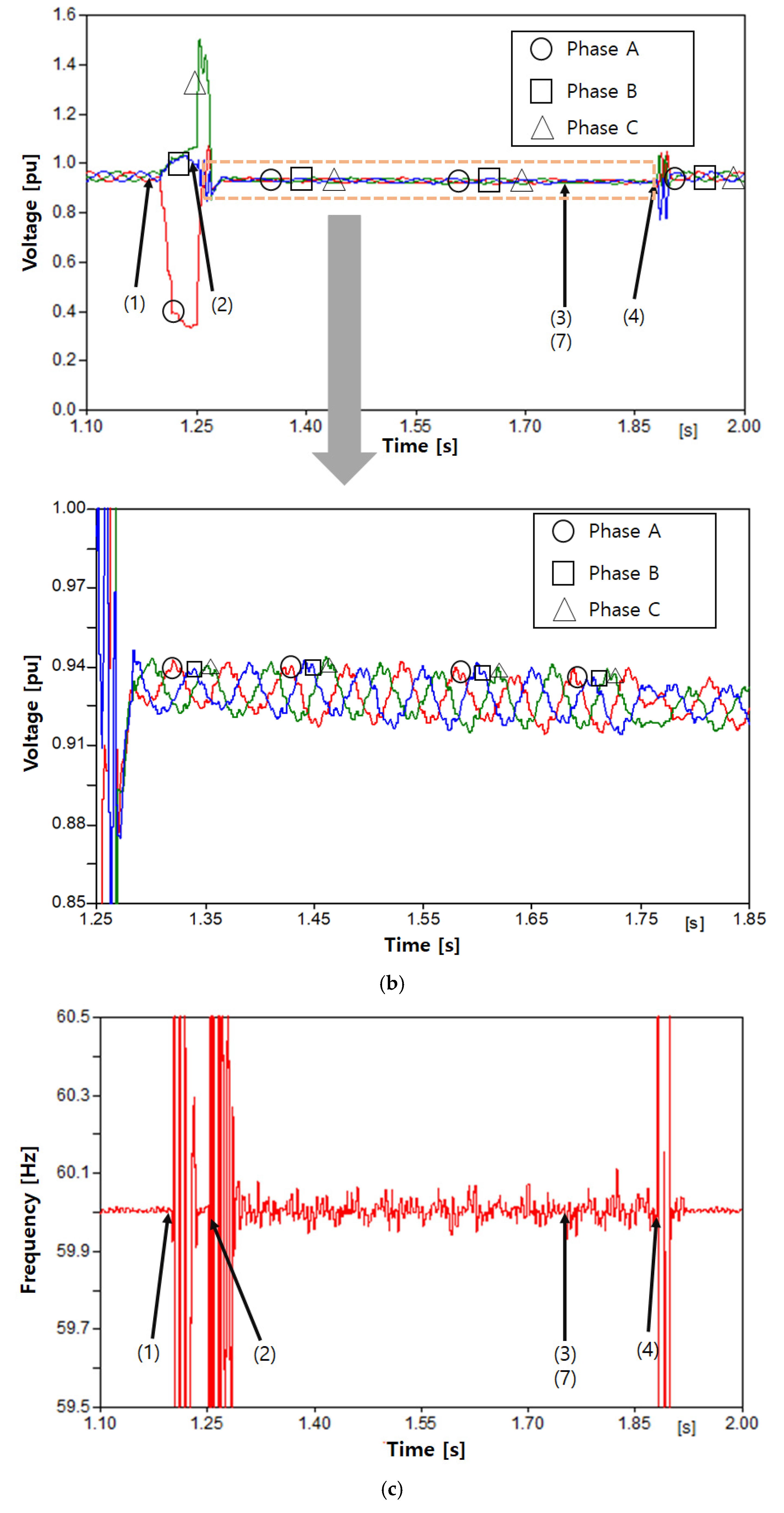
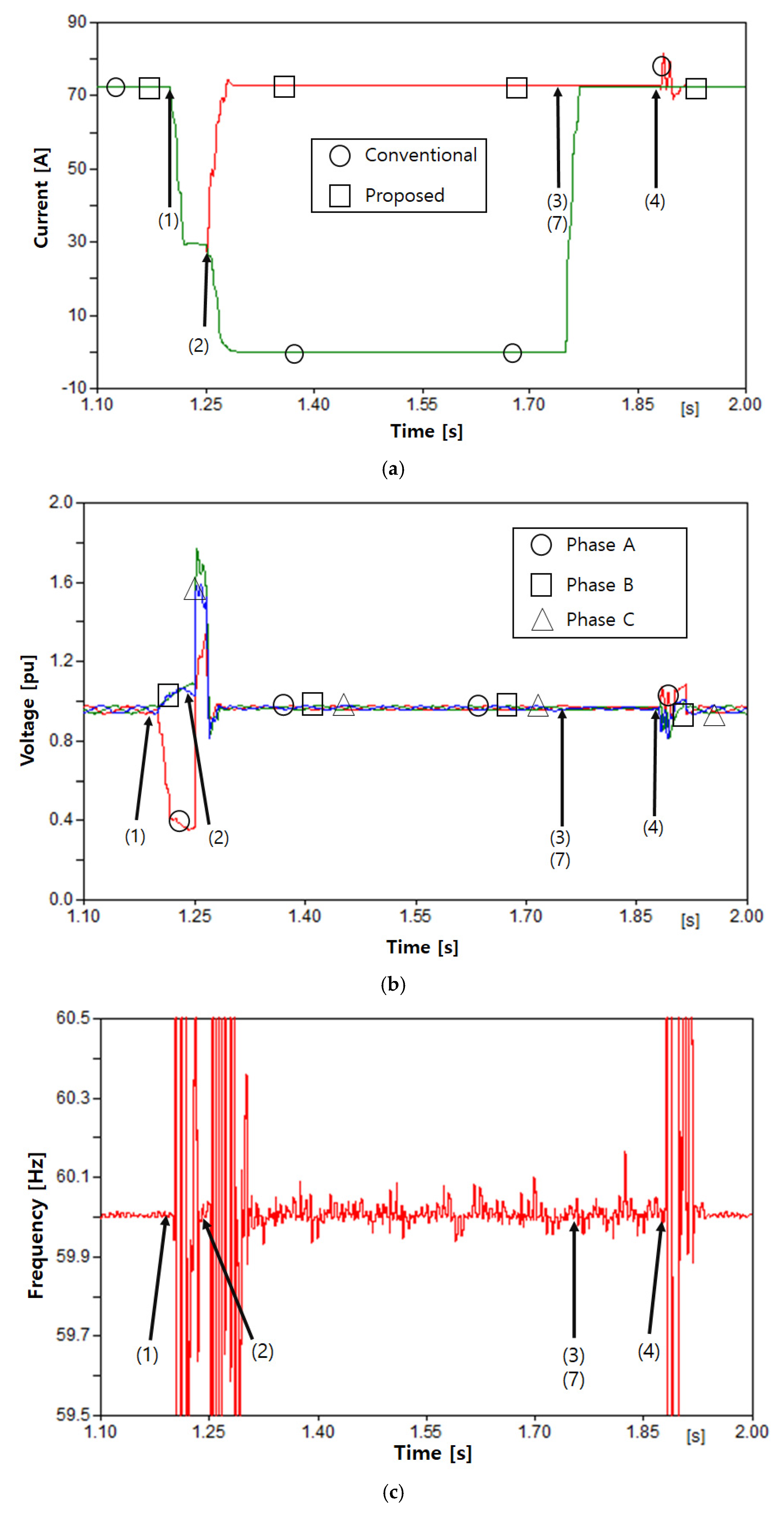
Figure 8a shows the current flowing to Load 2 in Case 1. Once the fault was cleared at 1.25 s, the current flowing to Load 2 at the conventional reclosing was zero and, hence, Load 2 experienced an outage before the reclosing at 1.75 s. However, in the case of the proposed reclosing method, the current continuously flowed to Load 2 due to the power supplied from the DG and BESS. Figure 8b shows the voltage at Bus 3, which is the PCC of the load, DG, and BESS. Once the fault occurred at 1.2 s, the voltage at faulty phase A was reduced. Following the opening of CB1 and CB3 at 1.25 s, the steady-state current was supplied from the DG and BESS and, hence, a normal voltage of 0.92~0.94 pu was maintained. After the reclosing of CB1 occurred at 1.88 s, the voltage fluctuates; however, the normal voltage appears after two cycles. Regarding Case 1, the capacity of the DG and BESS was smaller than that of the load. In this case, if the inverter connected with the DG does not have the reactive power control function, the inductive reactive power supplied from the DG and BESS was insufficient, and hence, the voltage fell below the normal range. However, the voltage within the normal range was maintained by injecting an insufficient inductive reactive power through the inverter control. Figure 8c shows the frequency of Bus 3 in Case 1, where the normal frequency range of 59.9–60.1 Hz was maintained.
4.2.2. Case 2
Figure 9a shows the current flowing to Load 2 in Case 2. The islanding operation occurred after the opening of CB1 and CB3 due to a fault. Nevertheless, the DG and BESS were not disconnected from the distribution system and maintained the power supply to Load 2; hence, no outage occurred. Regarding the conventional reclosing method, because the DG and BESS were disconnected from the distribution system during the islanding operation, the power could not be supplied to Load 2, so the load experienced an outage. Figure 9b,c shows the voltage and frequency of Bus 3 in Case 2, which were approximately 0.97 pu and 59.9–60.1 Hz, respectively. They were maintained within the steady-state range.
4.2.3. Case 3
Figure 10a shows the current flowing to Load 2 in Case 3. Normal current flowed to Load 2 from the DG and BESS, even though CB1 and CB3 were open after the fault occurrence. During conventional reclosing, the DG and BESS were disconnected from the distribution system and, hence, the load experienced an outage before reclosing at 1.75 s. Figure 10b,c shows the voltage and frequency at Bus 3 in Case 3. It was confirmed that both the voltage and frequency were maintained within the normal range. Regarding Case 3, the power supplied from the DG and BESS was larger than the load capacity. Therefore, if the reactive power control of the inverter was not performed, more inductive reactive power was supplied from the DG and BESS than the reactive power required for the load. The voltage rose above the steady-state range in this case. However, in the proposed method, because the inverter connected with the DG could perform the reactive power control, the capacitive reactive power was supplied from DG. Thus, the voltage was maintained within the normal range.
4.2.4. Case 4
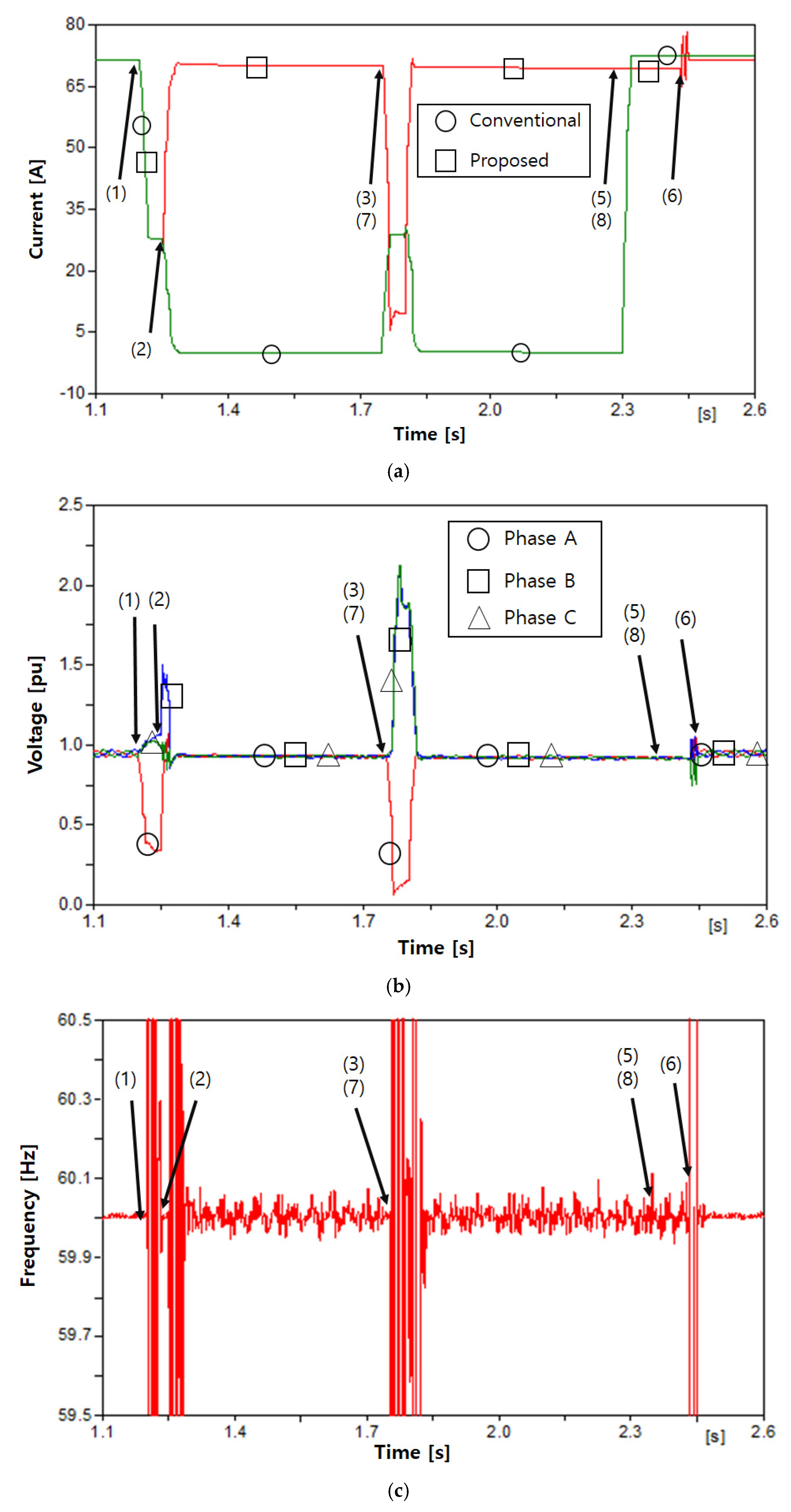
Figure 11a shows the current flowing to Load 2 in Case 4. Regarding conventional reclosing, the current was zero after the breaker opened in 1.25 s. The first reclosing failed because the fault remained; thus, the CB was reopened, and the current was again zero. The second reclosing was successful in 2.3 s and the normal current began to flow. Prior to the second reclosing, the load experienced an outage. The proposed reclosing scheme showed that the current was continuously supplied from the DG and BESS even after the breaker opened in 1.25 s. Therefore, no outage occurred. Figure 11b,c shows the voltage and frequency at Bus 3, where the voltage and frequency were observed to be within the normal range of about 0.92 pu and 59.9–60.1 Hz, respectively. This was because the steady-state voltage was supplied from the DG and BESS through the reactive power control of the inverter despite the islanding operation.
4.2.5. Case 5
Figure 12a shows the current flowing to Load 2 in Case 5. During the conventional reclosing method, two instances of reclosing at 1.75 s and 2.3 s failed and the current became zero. However, in the proposed reclosing method, the steady-state current was continuously supplied from the DG and BESS. Figure 12b,c shows the voltage and frequency at Bus 3, which were maintained within the steady-state range.
Despite the permanent fault, the load did not experience an outage due to the steady-state power supply from the DG and BESS. When the BESS was completely discharged during the permanent fault, the power was supplied by the DG alone. If the voltage and frequency could not be maintained at this time, the DG was also disconnected from the distribution system.
4.2.6. Simulation Results of Protective Relay 2
The various simulations were also performed when faults in Table 1 occurred in Line 2. According to the proposed algorithm, the reclosing of CB4 was performed and the fault clearance was judged. Subsequently, the reclosing of CB2 was performed after completing the synchronism check. Additionally, before reclosing, it was confirmed that the steady-state power was continuously supplied to Load 2 by the DG and BESS 2, and the voltage and frequency were maintained within the normal range.
5. Conclusions
In this study, we analyze the problem of applying the conventional reclosing method in the distribution system with DG and a BESS, and propose a new reclosing method for a distribution system with DG and a BESS based on the analysis. Using the proposed reclosing method, an additional CB is installed in the line of the distribution system. When a fault occurs, the two CBs installed in the line are opened simultaneously. Thereafter, although the islanding operation condition occurs, the DG and BESS do not become disconnected. The inverter connected to the DG performs the reactive power control function to maintain a steady voltage during the islanding operation. Once the predetermined fixed dead time has elapsed, the breaker installed near the DG and BESS is first reclosed, and the fault clearance is judged using the current flowing to the fault point. When the fault is removed, the breaker installed on the main power source is finally reclosed after the synchronism check between the main source and the DG and BESS.
The proposed reclosing methods were modeled using EMTP for method verification. The simulations were performed according to the variation in the capacity of the DG and fault clearance time to confirm whether the normal voltage and frequency were maintained during the intended islanding operation. Consequently, the steady-state power was supplied to the load from the DG and BESS before reclosing, so the load did not experience an outage.
Two limitations in realizing the proposed method should be considered. The first limitation is a cost problem. CBs should be installed in the distribution line. Additionally, the electrical installation for the communication should be installed, which again requires a high cost. The second limitation is the type of DG. In this paper, the photovoltaic system, which is interconnected via an inverter, is considered. Generally, the fault current contribution from the inverter is smaller than that from the synchronous generator. Therefore, the reclosing of the CB near the DG is first attempted to minimize the damage by the fault current injection due to the reclosing failure. When DG with a synchronous generator is applied, it is not a meaningful method. To overcome these limitations, we will study the reclosing method considering the cost and the type of DG in the future.
Funding
This work was supported by a 2018 Yonam Institute of Technology grant.
Conflicts of Interest
The author declares no conflict of interest.
References
- Zhang, F.; Meng, K.; Xu, Z.; Dong, Z.Y.; Zhang, L.; Wan, C.; Liang, J. Battery ESS Planning for Wind Smoothing via Variable-interval Reference Modulation and Self-adaptive SOC Control Strategy. IEEE Trans. Sustain. Energy 2017, 8, 695–707. [Google Scholar] [CrossRef]
- Reihani, E.; Motalleb, M.; Ghorbani, R.; Saoud, L.S. Load peak shaving and power smoothing of a distribution grid with high renewable energy penetration. Renew. Energy 2016, 86, 1372–1379. [Google Scholar] [CrossRef]
- Castillo, A.; Gayme, D.F. Grid-scale energy storage applications in renewable energy integration: A survey. Energy Convers. Manag. 2014, 87, 885–894. [Google Scholar] [CrossRef]
- Damiano, A.; Gatto, G.; Marongiu, I.; Porru, M.; Serpi, A. Real-Time Control Strategy of Energy Storage Systems for Renewable Energy Sources Exploitation. IEEE Trans. Sustain. Energy 2014, 5, 567–576. [Google Scholar] [CrossRef]
- Shu, Z.; Jirutitijaroen, P. Optimal Operation Strategy of Energy Storage System for Grid-Connected Wind Power Plants. IEEE Trans. Sustain. Energy 2014, 5, 190–199. [Google Scholar] [CrossRef]
- Ju, L.; Tan, Z.; Yuan, J.; Tan, Q.; Li, H.; Dong, F. A bi-level stochastic scheduling optimization model for a virtual power plant connected to a wind-photovoltaic-energy storage system considering the uncertainty and demand response. Appl. Energy 2016, 171, 184–199. [Google Scholar] [CrossRef]
- Awad, A.S.A.; EL-Fouly, T.H.M.E.; Salama, M.M.A. Optimal ESS Allocation for Load Management Application. IEEE Trans. Power Syst. 2015, 30, 327–336. [Google Scholar] [CrossRef]
- Zhou, B.; Xu, D.; Chan, K.W.; Lia, C.; Cao, Y.; Bu, S. A two-stage framework for multi objective energy management in distribution networks with a high penetration of wind energy. Energy 2017, 135, 754–766. [Google Scholar] [CrossRef]
- El Nozahy, M.S.; Abdel-Galil, T.K.; Salama, M.M.A. Probabilistic ESS sizing and scheduling for improved integration of PHEVs and PV systems in residential distribution systems. Electr. Power Syst. Res. 2015, 125, 55–66. [Google Scholar] [CrossRef]
- Farzin, H.; Fotuhi-Firuzabad, M.; Moeini-Aghtaie, M. A Stochastic Multi-Objective Framework for Optimal Scheduling of Energy Storage Systems in Microgrids. IEEE Trans. Smart Grid 2017, 8, 117–127. [Google Scholar] [CrossRef]
- Saboori, H.; Hemmati, R. Maximizing DISCO profit in active distribution networks by optimal planning of energy storage systems and distributed generators. Renew. Sustain. Energy Rev. 2017, 71, 365–372. [Google Scholar] [CrossRef]
- Aghdam, T.S.; Karegar, H.K.; Zeineldin, H.H. Transient Stability Constrained Protection Coordination for Distribution Systems with DG. IEEE Trans. Smart Grid 2017. [Google Scholar] [CrossRef]
- Zeineldin, H.H.; Sharaf, H.M.; Ibrahim, D.K.; El-Zahab, E.E.-D.A. Optimal protection coordination for meshed distribution systems with DG using dual setting directional over-current relays. IEEE Trans. Smart Grid 2015, 6, 115–123. [Google Scholar] [CrossRef]
- Khanbabapour, S.; Golshan, M.E.H. Synchronous DG Planning for Simultaneous Improvement of Technical, Overcurrent, and Timely Anti-Islanding Protection Indices of the Network to Preserve Protection Coordination. IEEE Trans. Power Deliv. 2017, 32, 474–483. [Google Scholar] [CrossRef]
- Chen, X.; Li, Y.; Zhao, M.; Wen, A.; Liu, N. A coordinated strategy of protection and control based on wide-area information for distribution network with the DG. In Proceedings of the 2014 International Conference on Power System Technology, Chengdu, China, 20–22 October 2014. [Google Scholar]
- He, H.; Chen, L.; Yin, T.; Cao, Z.; Yang, J.; Tu, X.; Ren, L. Application of a SFCL for Fault Ride-Through Capability Enhancement of DG in a Microgrid System and Relay Protection Coordination. IEEE Trans. Appl. Supercond. 2016, 26. [Google Scholar] [CrossRef]
- Zhan, H.; Wang, C.; Wang, Y.; Yang, X.; Zhang, X.; Wu, C.; Chen, Y. Relay Protection Coordination Integrated Optimal Placement and Sizing of Distributed Generation Sources in Distribution Networks. IEEE Trans. Smart Grid 2016, 7, 55–65. [Google Scholar] [CrossRef]
- Abdel-Ghany, H.A.; Azmy, A.M.; Elkalashy, N.I.; Rashad, E.M. Optimizing DG penetration in distribution networks concerning protection schemes and technical impact. Electr. Power Syst. Res. 2015, 128, 113–122. [Google Scholar] [CrossRef]
- Coffele, F.; Booth, C.; Dyśko, A. An Adaptive Overcurrent Protection Scheme for Distribution Networks. IEEE Trans. Power Deliv. 2015, 30, 561–568. [Google Scholar] [CrossRef] [Green Version]
- Sharaf, H.M.; Zeineldin, H.H.; Ibrahim, D.K.; EL-Zahab, E.E.-D.A. A proposed coordination strategy for meshed distribution systems with DG considering user-defined characteristics of directional inverse time overcurrent relays. Int. J. Electr. Power Energy Syst. 2015, 65, 49–58. [Google Scholar] [CrossRef]
- Srivastava, A.; Mohanty, S.R.; Panda, B. Optimal Over-current Relay Coordination with Distributed Generation Using Hybrid Particle Swarm Optimization–Gravitational Search Algorithm. Electr. Power Compon. Syst. 2016, 44, 506–517. [Google Scholar] [CrossRef]
- Ates, Y.; Uzunoglu, M.; Karakas, A.; Boynuegri, A.R.; Nadar, A.; Dag, B. Implementation of adaptive relay coordination in distribution systems including distributed generation. J. Clean. Prod. 2016, 12, 2697–2705. [Google Scholar] [CrossRef]
- Shih, M.Y.; Conde, A.; Leonowicz, Z.; Martirano, L. An Adaptive Overcurrent Coordination Scheme to Improve Relay Sensitivity and Overcome Drawbacks due to Distributed Generation in Smart Grids. IEEE Trans. Ind. Appl. 2017, 53, 5217–5229. [Google Scholar] [CrossRef]
- Kar, S.; Samantaray, S.R. Data-mining-based intelligent anti-islanding protection relay for distributed generations. IET Gener. Transm. Distrib. 2014, 8, 629–639. [Google Scholar] [CrossRef]
- Gupta, P.; Bhatia, R.S.; Jain, D.K. Active ROCOF Relay for Islanding Detection. IEEE Trans. Power Deliv. 2017, 32, 420–429. [Google Scholar] [CrossRef]
- Seo, H.-C. New adaptive reclosing technique using second-order difference of THD in distribution system with BESS used as uninterruptible power supply. Int. J. Electr. Power Energy Syst. 2017, 90, 315–322. [Google Scholar] [CrossRef]
- Seo, H.-C. New Configuration and Novel Reclosing Procedure of Distribution System for Utilization of BESS as UPS in Smart Grid. Sustainability 2017, 9, 507. [Google Scholar] [CrossRef]
- Seo, H.-C.; Rhee, S.-B. Novel adaptive reclosing scheme using wavelet transform in distribution system with battery energy storage system. Int. J. Electr. Power Energy Syst. 2018, 97, 186–200. [Google Scholar] [CrossRef]
- Heo, J.-Y.; Oh, Y.-S.; Seo, H.-C.; Kim, C.-H. An Adaptive Autoreclosure Scheme with Reference to Transient Stability for Transmission Lines. J. Electr. Eng. Technol. 2015, 10, 795–803. [Google Scholar] [CrossRef]
- Park, J.-H.; Seo, H.-C.; Kim, C.-H.; Rhee, S.-B. Development of Adaptive Reclosing Scheme Using Wavelet Transform of Neutral Line Current in Distribution System. Electr. Power Compon. Syst. 2016, 44, 426–433. [Google Scholar] [CrossRef]
- Seo, H.-C. New Adaptive Reclosing Technique in Unbalanced Distribution System. Energies 2017, 10, 1004. [Google Scholar] [CrossRef]
- De Sotomayor, A.A.; della Giustina, D.; Massa, G.; Dedè, A.; Ramos, F.; Barbato, A. IEC 61850-based adaptive protection system for the MV distribution smart Grid. Sustain. Energy Grids Netw. 2017. [Google Scholar] [CrossRef]
- Papaspiliotopoulos, V.A.; Korres, G.N.; Hatziargyriou, N.D. Adverse impact of distributed generation on protection of the Hellenic MV Network—Recommendations for protection scheme upgrade. CIRED Open Access Proc. J. 2017, 2017, 934–938. [Google Scholar] [CrossRef]
- Wheeler, K.A.; Elsamahy, M.; Faried, S.O. A Novel Reclosing Scheme for Mitigation of Distributed Generation Effects on Overcurrent Protection. IEEE Trans. Power Deliv. 2018, 33, 981–991. [Google Scholar] [CrossRef]
- Teimourzadeh, S.; Davarpanah, M.; Aminifar, F.; Shahidehpour, M. An Adaptive Auto-Reclosing Scheme to Preserve Transient Stability of Microgrids. IEEE Trans. Smart Grid 2016. [Google Scholar] [CrossRef]
- Luo, X.; Wang, J.; Dooner, M.; Clarke, J. Overview of current development in electrical energy storage technologies and the application potential in power system operation. Appl. Energy 2015, 137, 511–536. [Google Scholar] [CrossRef]
- KEPCO. Technical Standard for Interconnecting Distributed Generation with Distribution System 2017; KEPCO: Naju, Korea, 2017. [Google Scholar]
- Kim, J.-H.; Lee, S.-J.; Kim, E.-S.; Kim, S.-K.; Kim, C.-H.; Prikler, L. Modeling of Battery for EV using EMTP/ATPDraw. J. Electr. Eng. Technol. 2014, 9, 98–105. [Google Scholar] [CrossRef]
- Stetz, T. Autonomous Voltage Control Strategies in Distribution Grids with Photovoltaic Systems—Technical and Economic Assessment. Ph.D. Thesis, University of Kassel, Kassel, German, 2013. [Google Scholar]
Figure 1.
Distribution system model with distributed generation (DG) and a battery energy storage system (BESS).
Figure 1.
Distribution system model with distributed generation (DG) and a battery energy storage system (BESS).

Figure 2.
Flow of fault current.
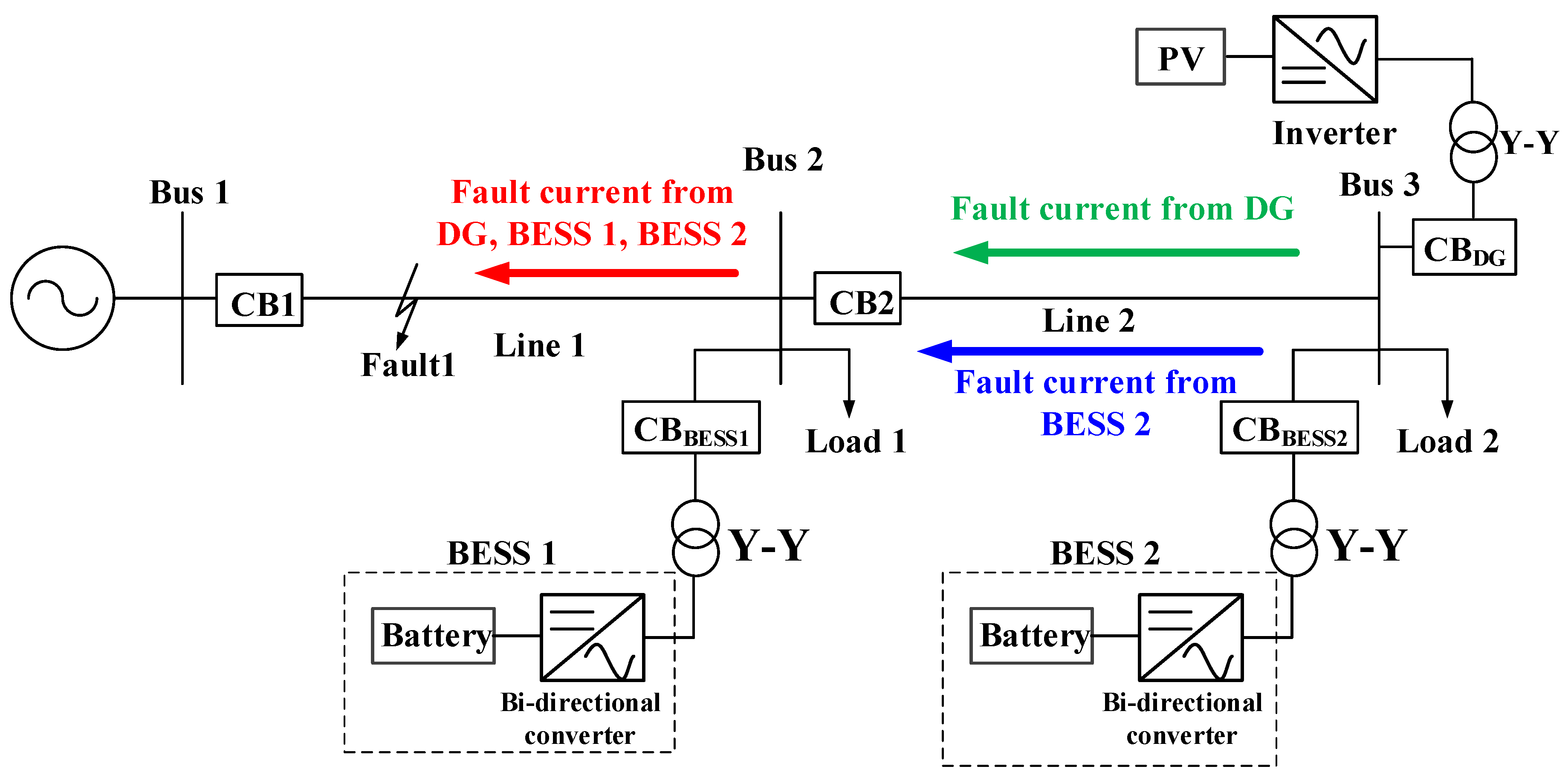
Figure 3.
Flow of fault current after circuit breaker 2 (CB2) opening.

Figure 4.
System configuration for establishing the proposed reclosing method.

Figure 5.
Flowchart of the proposed reclosing method at protective relay 1.

Figure 6.
Current flow after the reclosing of CB3 when the fault is not removed.

Figure 7.
Current flow after the reclosing of CB3 when the fault is removed.

Figure 8.
Simulation results of Case 1: (a) current flowing to Load 2; (b) voltage at Bus 3; (c) frequency at Bus 3.
Figure 8.
Simulation results of Case 1: (a) current flowing to Load 2; (b) voltage at Bus 3; (c) frequency at Bus 3.


Figure 9.
Simulation results of Case 2: (a) current flowing to Load 2; (b) voltage at Bus 3; (c) frequency at Bus 3.
Figure 9.
Simulation results of Case 2: (a) current flowing to Load 2; (b) voltage at Bus 3; (c) frequency at Bus 3.

Figure 10.
Simulation results of Case 3: (a) current flowing to Load 2; (b) voltage at Bus 3; (c) frequency at Bus 3.
Figure 10.
Simulation results of Case 3: (a) current flowing to Load 2; (b) voltage at Bus 3; (c) frequency at Bus 3.

Figure 11.
Simulation results of Case 4: (a) current flowing to Load 2; (b) voltage at Bus 3; (c) frequency at Bus 3.
Figure 11.
Simulation results of Case 4: (a) current flowing to Load 2; (b) voltage at Bus 3; (c) frequency at Bus 3.

Figure 12.
Simulation results of Case 5: (a) current flowing to Load 2; (b) voltage at Bus 3; (c) frequency at Bus 3.
Figure 12.
Simulation results of Case 5: (a) current flowing to Load 2; (b) voltage at Bus 3; (c) frequency at Bus 3.

Table 1.
Simulation conditions.
| Case | Fault Occurrence [s] | Fault Clearance Time [s] | DG Capacity [kW] |
|---|---|---|---|
| Case 1 | 1.2 | 1.4 | 1000 |
| Case 2 | 1.2 | 1.4 | 1700 |
| Case 3 | 1.2 | 1.4 | 4500 |
| Case 4 | 1.2 | 2 | 1000 |
| Case 5 | 1.2 | - | 4500 |
© 2018 by the author. Licensee MDPI, Basel, Switzerland. This article is an open access article distributed under the terms and conditions of the Creative Commons Attribution (CC BY) license (http://creativecommons.org/licenses/by/4.0/).
Share and Cite
MDPI and ACS Style
Seo, H.-C. Development of Reclosing Method in a Distribution System with Distributed Generation and Battery Energy Storage System. Energies 2018, 11, 1407. https://doi.org/10.3390/en11061407
AMA Style
Seo H-C. Development of Reclosing Method in a Distribution System with Distributed Generation and Battery Energy Storage System. Energies. 2018; 11(6):1407. https://doi.org/10.3390/en11061407
Chicago/Turabian StyleSeo, Hun-Chul. 2018. "Development of Reclosing Method in a Distribution System with Distributed Generation and Battery Energy Storage System" Energies 11, no. 6: 1407. https://doi.org/10.3390/en11061407
Note that from the first issue of 2016, this journal uses article numbers instead of page numbers. See further details here.