Design, Analysis, and Evaluation of a Compact Electromagnetic Energy Harvester from Water Flow for Remote Sensors


Ocean College, Zhejiang University, Zhoushan 316000, China
*
Author to whom correspondence should be addressed.
Energies 2018, 11(6), 1424; https://doi.org/10.3390/en11061424
Submission received: 4 May 2018
/
Revised: 28 May 2018
/
Accepted: 30 May 2018
/
Published: 2 June 2018
(This article belongs to the Section I: Energy Fundamentals and Conversion)
Abstract
:This paper develops an electromagnetic energy harvester, which can generate small-scale electricity from non-directional water flow in oceans or rivers for remote sensors. The energy harvester integrates a Tesla disk turbine, a miniature axial-flux permanent magnet generator, and a ring cover with symmetrical grooves which are utilized to rectify flow direction. A compact structure is achieved by mounting the permanent magnets of the generator directly on the end surfaces of the turbine rotor. Theoretical analysis is implemented to illustrate the energy conversion process between flow kinetic form and electrical form. Additionally, a mathematical model is developed to investigate the magnetic field distribution produced by the cubical permanent magnets as well as parametric effect. Plastic prototypes with a diameter of 65 mm and a height of 46 mm are fabricated by using a 3D printing technique. The effect of the groove angle is experimentally investigated and compared under a no-load condition. The prototype with the optimal groove angle can operate at flow velocity down to 0.61 m/s and can induce peak-to-peak electromotive force of 2.64–11.92 V at flow velocity of 0.61–1.87 m/s. It can be observed from the results that the analytical and the measured curves are in good accordance. Loaded experiments show that the output electrical power is 23.1 mW at flow velocity of 1.87 m/s when the load resistance is approximately equal to the coil resistance. The advantages and disadvantages of the proposed energy harvester are presented through comparison with existing similar devices.
1. Introduction
Energy harvesting is an attractive technique for a wide variety of wireless network sensors and nodes [1,2,3], wearable robotics [4,5], biomedical implants [6,7], as well as portable electronics [8,9,10], which have a strong demand for being battery free. Kinetic energy harvesters usually employ a transduction mechanism, such as piezoelectric or an electromagnetic type, to convert ambient or human motion into electrical energy [11]. Kinetic energy in fluid flow is a remarkable harvesting source which mainly comes in two forms, including gas flow and liquid flow. They can be easily found in the natural environment, industrial piping, and even the human body [12].
An energy harvesting approach is to make the flow self-excited based on an instable physical phenomenon, such as vortex, flutter, resonance, and so forth, and then harvest the flow-induced vibration energy with conventional transduction mechanisms. The authors of [13] proposed an energy harvesting eel consisting of a bluff body and piezoelectric elements to convert flow energy available in oceans and rivers to electrical power. Coupled simulations under different Reynolds numbers and load resistance were implemented in Reference [14] to evaluate the level of harvested power from the dynamical system including fluid flow, body motion, and electrical transduction. The flow energy harvesting module in [15,16] employed a circular rigid cylinder supported by linear springs to induce vortex, and the vibration power was transmitted by a gear-belt system and a rotary generator. In Reference [17], the authors converted the flow energy into pressure oscillation by using a Kármán vortex street behind a bluff body, which resulted in a periodical displacement of a permanent magnet located under a coil, and therefore electrical power generation. In [18], the flow-induced vibration and energy harvesting of cylinders with different cross sections were investigated through two-dimensional unsteady Reynolds-averaged Navier–Stokes simulations. To enhance energy conversion efficiency, the vortex-induced vibration of a circular cylinder in a dual-mass configuration was modeled and theoretically studied in Reference [19]. The authors of [20] proposed and tested a bioinspired piezo-leaf architecture which converted wind energy into electrical energy by a flow-induced fluttering motion. Resonant cavities were also utilized to convert air flow into mechanical vibration for energy harvesting as presented in References [21,22]. In general, the concept of flow-induced vibration energy harvesting is complex, for it requires both excitation and transduction mechanisms.
A more direct idea for flow energy harvesting is miniaturization of conventional blade turbines and electrical generators. In Reference [6], the authors developed an electromagnetic energy harvester consisting of a turbine rotor with magnets and external coils with ferrite cores, using a cardiovascular system as a power source for medical implants. In [23], a tiny portion of the kinetic energy in fluid flow was extracted and stored in a capacitor to supply battery-free flowmeters in pipes by combining a small-scale blade turbine and a coreless generator. The authors of [24] developed a small-scale axial-flux permanent magnet generator aiming at easy integration with an axial-flow microturbine for energy harvesting. The authors of [25] employed a wind turbine generator to harvest an average electrical power of 7.7 mW at an average wind speed of 3.62 m/s for powering a wireless sensor node, which consumed 3.5 mW for predicting wildfire spread. In addition, 3D printing technology was also employed to fabricate miniature wind turbines for energy harvesting as presented in [26]. Aiming at low-speed air flow, an energy harvesting topology consisting of a small fan with embedded permanent magnets and a piezoelectric beam was proposed to achieve higher efficiency and power density in [27]. However, the relatively high viscous drag on the blades at low Reynolds numbers may deteriorate the performance of the miniature blade turbines [9]. Tesla disk turbines, which have the advantages of easy manufacture, low noise, and no blades, are suitable candidates for flow energy harvesters [28,29,30]. In Reference [7], the authors developed a miniature Tesla disk turbine connected with a generator for intracorporeal energy harvesting. The authors of [29,30] reported the feasibility of harvesting the kinetic energy in turbulent air and rainwater flow by using Tesla disk turbines with different diameters. However, the structure where the fluid turbine and the electrical generator are connected in parallel along the shaft usually results in relatively large volumes and low power density [31,32]. In addition, the aforementioned Tesla disk turbines are driven by fluid flow in pipes where the working fluid is injected nearly tangentially to rotating disks through certain nozzles. Therefore, they cannot be directly applied to energy harvesting from fluid flow without constant direction.
Electromagnetic energy harvesting is of great research interest in recent years [33,34,35,36]. This paper proposes an electromagnetic energy harvester to utilize the kinetic energy from water flow with random direction in oceans or rivers for remote sensors. The device highly integrates a Tesla disk turbine, a miniature axial-flux permanent magnet generator, and a ring cover with symmetrical grooves which are employed to rectify flow direction together. The permanent magnets of the generator are directly mounted on the end surfaces of the turbine disks so as to reduce the size of the energy harvester. Due to the compact structure, it is easy to integrate with remote sensors such as autonomous oceanographic sampling networks. The energy conversion process is theoretically analyzed, and the energy harvesting performance is verified by experimental results. The rest of the paper is organized as follows. Section 2 describes the design and prototype fabrication of the flow energy harvester. Section 3 presents the analysis of hydrokinetic energy and power generation. Section 4 presents experimental setup and results under no-load and loaded conditions. Finally, conclusions are drawn in Section 5.
2. Machine Description and Prototype
2.1. Structure and Principle
The proposed flow energy harvester has a compact cylindrical structure which combines fluid and electromagnetic mechanisms together. Figure 1 presents the schematic diagrams of the flow energy harvester on radial and axial cross sections respectively. The turbine rotor mainly consists of a series of disks installed with uniform gaps on a shaft which is supported by a pair of bearings. The disks are separated by using sleeves and fixed on the shaft using a circlip. Permanent magnets with alternative axial magnetization direction are mounted on the end surfaces of the turbine rotor, and coils are fixed in the end caps correspondingly. The permanent magnets and the coils form a miniature axial-flux permanent magnet generator. A ring cover with symmetrical grooves is fixed on the outer of the energy harvester so as to convert water flow with random direction to the direction almost tangential to the disks. Symbol α is used to denote the groove angle, of which the effect on energy harvesting performance will be investigated. It should be mentioned that the outer shaft is designed only for rotation speed measurement in this study and can be eliminated in practical application.
The brief operation principle of the energy harvester is illustrated as follows. When the device is located in regions with horizontal water flow, an amount of water will flow into the gaps between disks through the grooves of the ring cover. Then a viscous drag force will be generated to drive the turbine rotor as well as the attached permanent magnets to rotate according to Newton’s viscous law, which results in periodic variation of the magnetic flux through the coils. Based on electromagnetic induction theory, electromotive forces will be induced in the coils and current will be generated when the coils are connected to electrical loads.
2.2. Prototype Fabrication
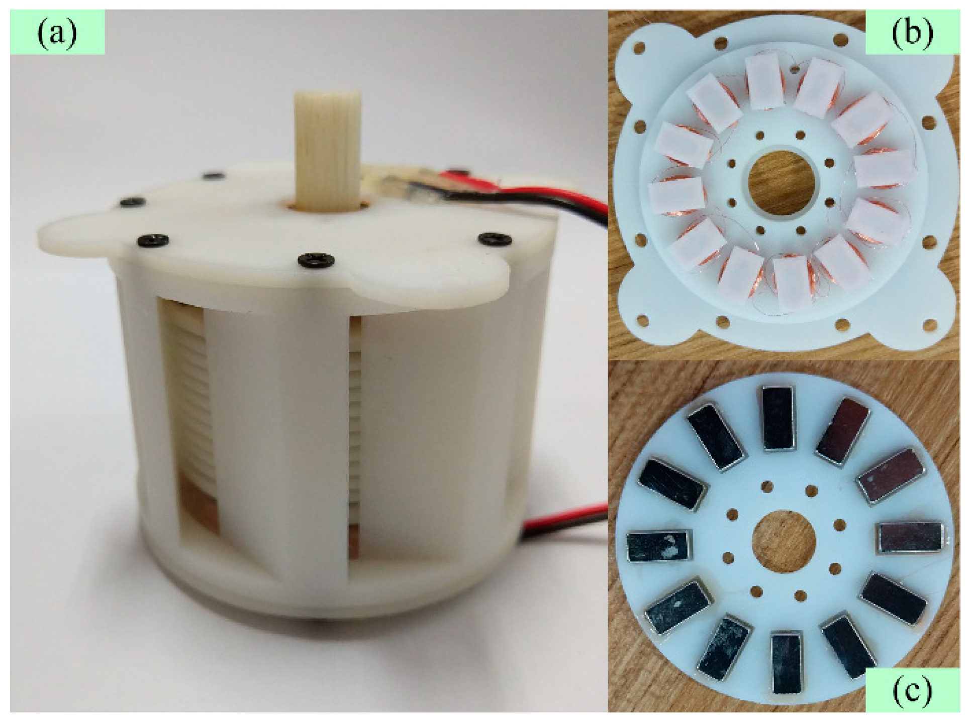
Prototypes are developed to experimentally evaluate the flow energy harvester performance as shown in Figure 2. The main parameters of the prototypes are given in Table 1. To investigate the effect of the groove angle, three prototypes with groove angles of 15, 25, and 35 degrees are fabricated for comparison. The fabrication process is described as follows. Firstly, the disks, the sleeves, the shaft, the end caps, and the cover are designed based on 3D modeling software (SolidWorks, v2015, Dassault Systemes, Vélizy-Villacoublay, France), and fabricated by using plastic material and a 3D printing technique with precision of 0.1 mm. Secondly, the permanent magnets, which employ the material of NdFeB with the model of N38, are mounted on the end surfaces of two disks. Then the disks and the sleeves are fixed on the shaft in a sequence with the help of the circlip. Thirdly, the coils are wound on a series of separate plastic teeth by using copper wires, and then the teeth are installed on the end caps. Finally, the rotor part, the end caps, and the cover are assembled by using bearings and bolts.
3. Energy Conversion Analysis
3.1. Hydrokinetic Energy
The hydrokinetic energy of water flow depends on the flow mass and the flow velocity, and it can be expressed as:
where m is the flow mass and vf is the flow velocity. The flow mass can be written as m = ρV = ρAvft, where ρ is the water density, V is the flow volume, A is the groove area perpendicular to flow direction, and t is the time. Then the following expression can used to convert the hydrokinetic energy to mechanical power at a specific time interval:
It is assumed that the water flow is injected through a stationary disk of the turbine rotor at velocity u due to the outer ring cover as shown in Figure 2 and the relative velocity of the disk is −u. The viscous drag force on the disk will act in the direction of the water flow, opposing the flow motion. According to Newton’s viscous law, the shear stress on the disk is generated by the velocity gradient as:
where r is the radial distance from the shaft center, θ is the azimuth angle, µ is the water viscosity, and h denotes the height. Then the shear stress gives rise to a mechanical torque on the disk which can be calculated by [29]:
where Ri and Ro are the inner and the outer radius of the disk respectively.
If the total mechanical torque is larger than the frictional torque, the turbine rotor will start rotating. Since the disk rotation speed increases, the relative velocity of the water flow with respect to the disk decreases, until a steady state is reached when the disk rotates at a constant speed at which the frictional torque is balanced by the mechanical driven torque.
3.2. Power Generation Model
As the mechanical torque drives the disks to rotate, the permanent magnets mounted on the end surfaces of the turbine disks will rotate too. The permanent magnets and the coils fixed in the end caps form an ironless axial-flux permanent magnet generator. Neglecting armature reaction due to relative large airgap length, the magnetic field is mainly produced by a series of cubical permanent magnets distributed axially symmetrically. Therefore, the magnetic flux density in three-dimensional coordinates can be derived as a function of position based on the Coulombian model. It is defined that the coordinate axes are in parallel with the edges of one cubical permanent magnet and the coordinate origin is on the rotation axis of the generator. As shown in Figure 3, the vertices of the cubical permanent magnet are at points (xi, yj, zk) and the subscripts i, j, and k are equal to 1 or 2. Then the z-axis component of magnetic flux density at point (x, y, z) due to the z-polarized cubical permanent magnet can be calculated as [37]:
where J is the magnetization of the permanent magnet, μ0 is the free space permeability, and ξijk is expressed as:
It is assumed that there are N cubical permanent magnets distributed symmetrically on one end surface. Therefore, the angle interval between two adjacent magnets is equal to 2π/N. By using rotation transformation, the position of the point (x, y, z) in the local coordinate of the λth (1 ≤ λ ≤ N) magnet can be expression as:
Considering the alternative magnetization directions of the permanent magnets, the total magnetic flux density at point (x, y, z) can be calculated as:
Then, the magnetic flux through a coil turn can be obtained by integrating the flux density over the corresponding area, and the magnetic flux through a coil can be calculated as a sum of the flux through every coil turn at the specific location by the following expression
where S is the coil area and M is the turn number per coil. According to the law of electromagnetic induction, the induced electromotive force can be derived by calculating the derivative of the coil flux with respect to time. Since the coil number is equal to the magnet number and the adjacent coils are wound in opposite directions in this design, the total induced electromotive force of the electromagnetic energy harvester can be simply given as:
Assuming a resistive load is connected, the output voltage and electrical power can be expressed respectively as:
where Rl is the load resistance, Rc and Lc are the coil resistance and the coil inductance of the electromagnetic energy harvester, and f is the frequency of alternating current. In general, the resistive effect due to the coil inductance is ignorable in comparison with the coil resistance. The total efficiency of energy conversion from the water flow to the harvested electricity can be expressed as:
3.3. Parametric Analysis
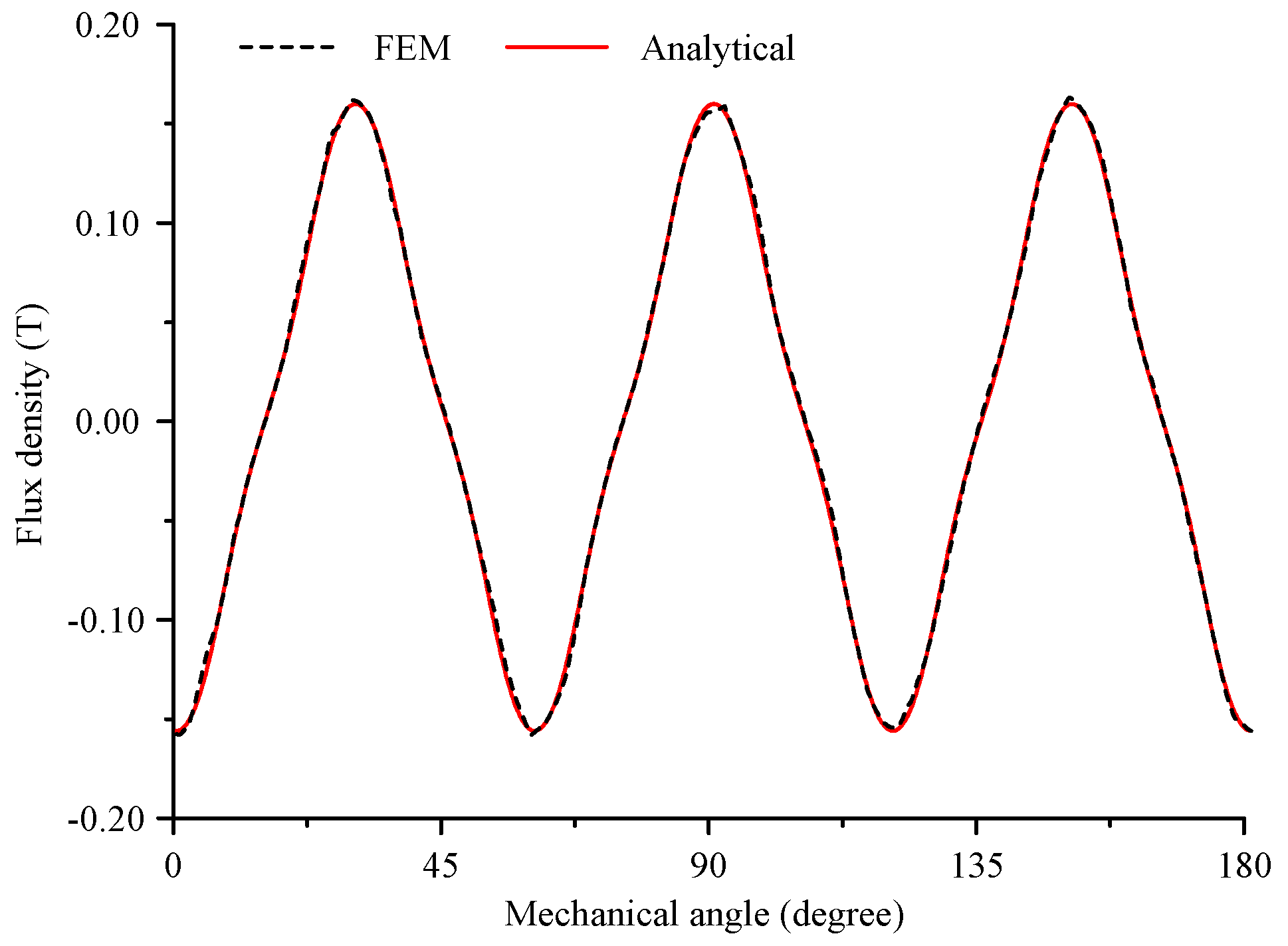
In this section, the effects of the main parameters on the magnetic field distribution are investigated based on the electromagnetic energy conversion model. Firstly, the effectiveness of the electromagnetic model is verified by using the 3D finite element method (FEM) which is performed in Maxwell software (v16.0, Ansoft, Canonsburg, PA, USA). In the FEM calculation, the mesh length is set to 0.4 mm and the involved parameters can be found in Table 1. Figure 4, Figure 5 and Figure 6 present the comparison between the flux density calculated by the FEM and the analytical model through the coils at the radius of 14 mm, 19 mm, and 24 mm, respectively. It can be seen that the two group curves agree with each other very well in general. There is a little irregularity in the FEM results because the mesh cannot be perfectly uniform. The flux density reaches maximum quantity at the center of every coil according to the results. In addition, the flux density curves tend to be distorted from sinusoidal waveform with the increase of the radius.
Figure 7 presents the magnitude of the magnetic flux through coils varying with main dimensional parameters including the airgap length, the magnet thickness, the magnet length, and the coil position. It can be observed that the flux magnitude decreases with the increase of the airgap length. In general, a small airgap length is beneficial to electromagnetic energy conversion as well as power density, but it gives rise to challenges with device fabrication. Therefore, in the prototype’s design the airgap length is 1.5 mm, which is a tradeoff between power density and fabrication difficulty. The flux magnitude increases and tends to be saturated with the increase of the magnet thickness and the magnet length. To avoid waste of magnetic material, the thickness and the length are chosen as 3 mm and 10 mm respectively in this work. The figure also shows that the flux magnitude is maximized when the coil position locates at the radius of 19 mm.
4. Results and Discussion
4.1. Experimental Setup
An experimental setup of which the schematic is shown in Figure 8 was developed to test the prototype performance of the flow energy harvester and verify the analytical model. Experiments are implemented in a glass flume where the water flow velocity is adjustable. A flow meter (LS300-A, Xiangruide, Nanjing, China) is employed to detect the water velocity flowing into the prototype. The flow meter has a measuring range of 0.01–4.00 m/s and a measuring accuracy of 1.5%. A tachometer (F931, Fluke, Everett, WA, USA) is employed to detect the rotation speed of the prototype. The tachometer has a measuring range of 1–99,999 rpm and a measuring accuracy of 0.02%. An oscilloscope (DPO2024B, Tektronix, Beaverton, OR, USA) is employed to measure the generated alternating voltage which is output from the prototype. Under no-load condition, the output terminals of the prototype are directly connected with the oscilloscope. Under loaded condition, the output terminals of the prototype are connected to a resistive load, of which the voltage is measured by the oscilloscope. The sampling time of data acquisition set to 0.01 s. To decrease experimental error, the results adopt the average value of three measurements in every test.
4.2. Under No-Load Condition
No-load experiments are carried out first. Figure 9 presents the induced electromagnetic force varying with flow velocity when the groove angles are equal to 15, 25, and 35 degrees respectively. It can be observed that the induced electromagnetic force increases with the groove angle. When flow velocity is as low as 0.61 m/s, only the prototype with a groove angle of 35 degrees can operate stably while the others cannot. The reason is that a larger groove angle results in a smaller flow area on the inner surface of the ring cover and a higher velocity of water injecting tangentially to rotating disks based on the momentum conservation law. It should be mentioned that 35 degrees is almost the maximum quantity for the designed prototypes, for the grooves will become closed if the groove angle is a little larger. Therefore, the groove angle of 35 degrees is considered as the optimal angle and the corresponding prototype is focused in the following. It can be seen that the induced electromagnetic force is almost proportional to the flow velocity. On the one hand, according to equations 3 and 4, the shear stress and the mechanical torque acting on the disks can be considered as linear to the water injecting velocity, for the gap length between the disks is relatively small. On the other hand, the frictional torque includes a constant starting part and a viscous part which is linear to the rotation speed based on the Coulomb friction model. Therefore, the experimental results are consistent with the expectation from the theoretical analysis. It was also found from the results that the optimal prototype can induce peak-to-peak electromotive force of 2.64–11.92 V at flow velocity of 0.61–1.87 m/s.
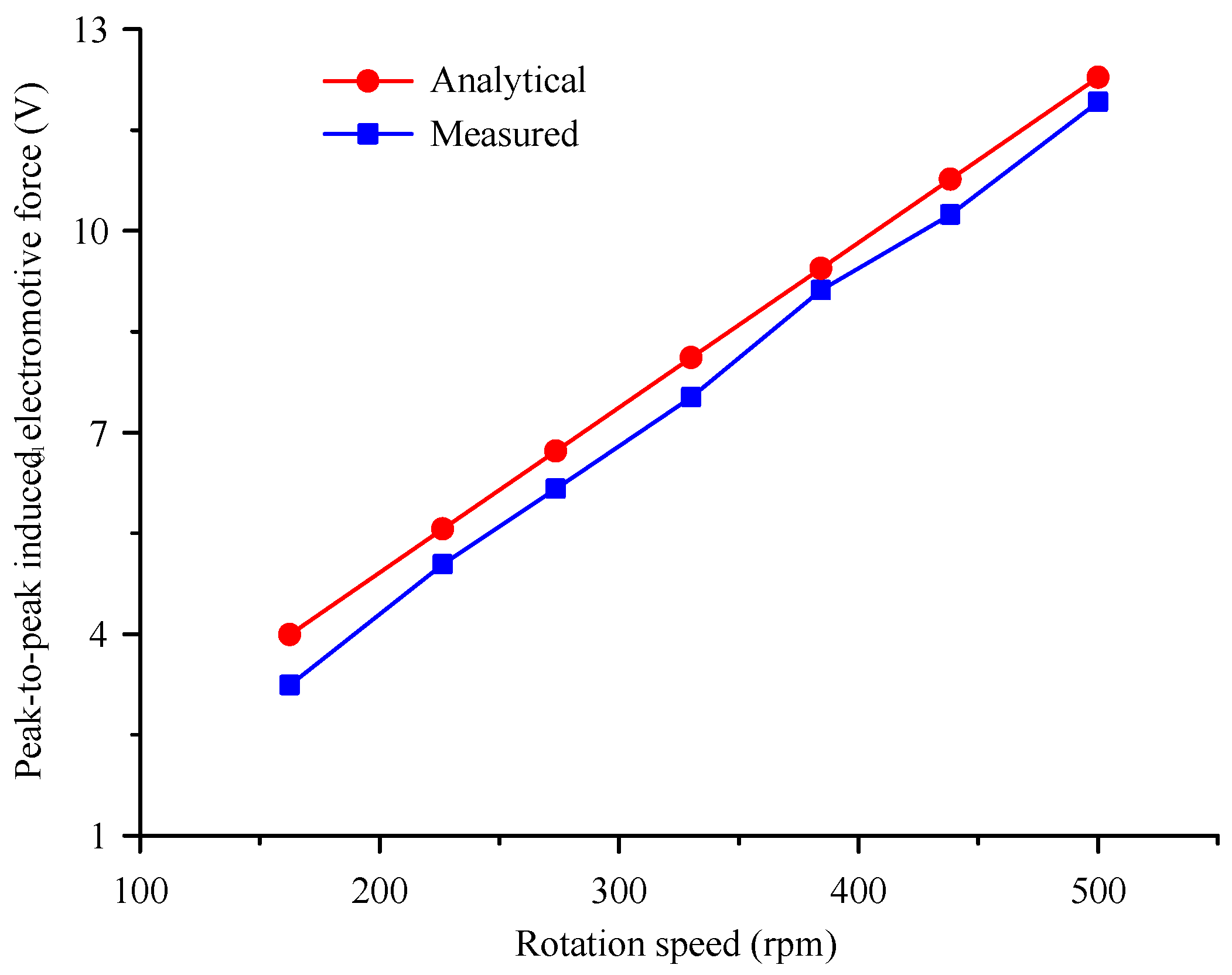
Figure 10 presents the comparison between the measured waveform and the analytical waveform of the induced electromotive force at the rotation speed of about 500 rpm. It can be observed that the two waveforms are in good accordance on the whole. The waveforms are almost sinusoidal because of the distributions of the coils and the permanent magnets. Figure 11 shows the peak-to-peak values of induced electromotive force varying with rotation speed. It can be seen that the induced electromotive force is linear with the rotation speed, and the slope is about 0.0238 V/rpm, which is a quantity related with the magnetic flux. The errors between the measured values and the analytical values may be caused in the numerical calculation by splitting the coil area into finite divisions.
4.3. Under Loaded Condition
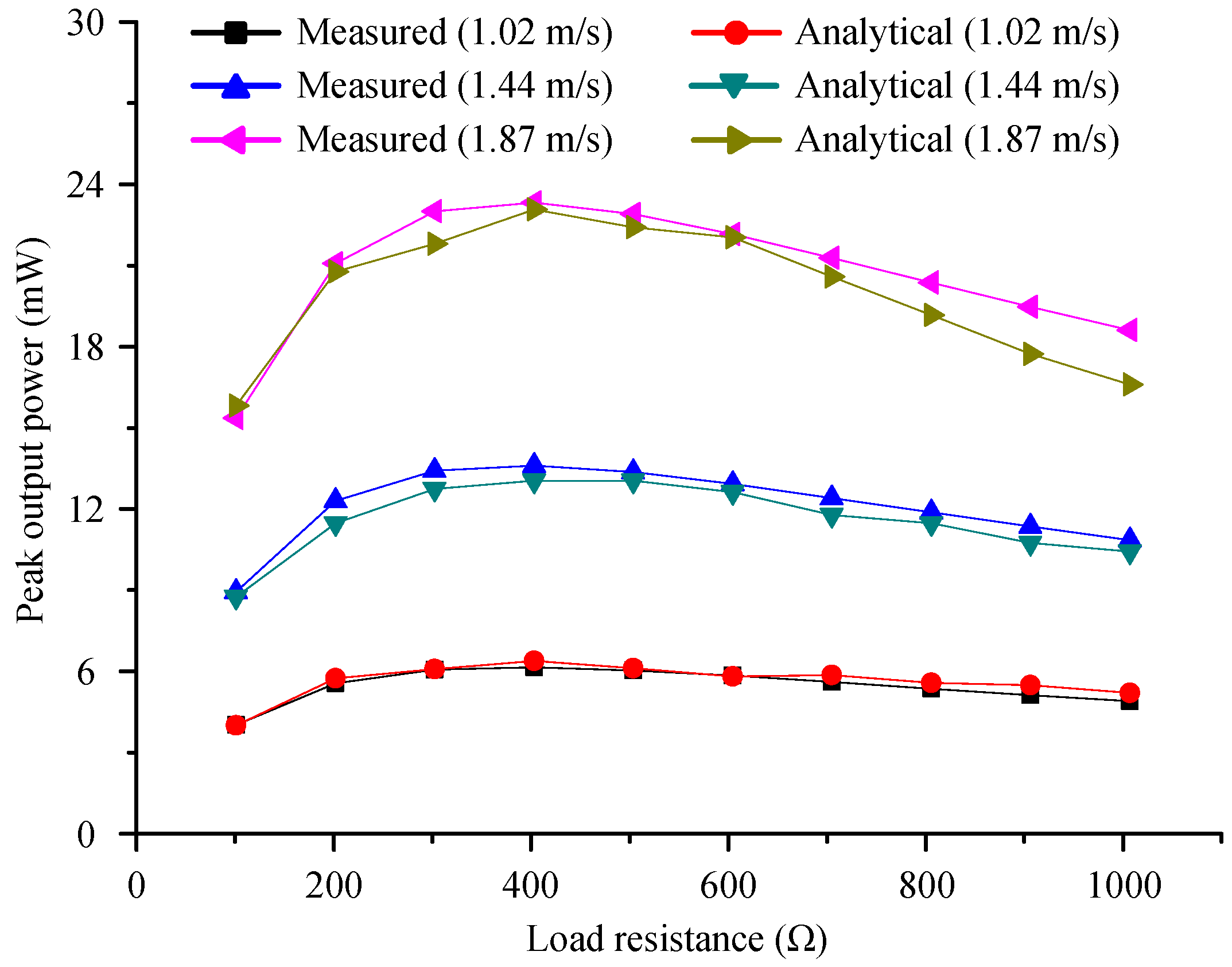
The experiments under loaded condition were also implemented. Figure 12 and Figure 13 present the experimental and analytical curves of the output voltage and electrical power, varying with the load resistance respectively. The analytical results are based on Equations (11) and (12) where the resistive effect due to the coil inductance is reasonably neglected. In general, the analytical curves are in good accordance with the experimental curves. It can be observed that the output voltage increases with the load resistance and tends to be saturated to the induced electromotive force when the load resistance is large enough. The output power maximizes when the load resistance is about 400 Ω, which is approximately equal to the coil resistance. Therefore, it can be deduced that the parasitic damping is much greater than the electromagnetic damping in the electromagnetic energy harvester [38]. The maximum output power reaches 23.1 mW at the flow velocity of 1.87 m/s. Substituting the corresponding parameters into Equation (13), it can be calculated that the maximum efficiency of the prototype is about 1.4%.
To evaluate the proposed design, Table 2 presents the comparison with other electromagnetic energy harvesters from fluid flow. It can be seen that both the output power and the efficiency in this study are comparable to the energy harvesters from the references. It also should be mentioned that this energy harvester has another two advantages. Firstly, it can harvest the hydrokinetic energy from non-directional water flow while the other two are only designed for fluid flow in pipes. Secondly, it has a compact structure by integrating the disks and the permanent magnets together, so its axial dimension is much smaller than the device in Reference [30].
5. Conclusions and Future Work
In summary, an integrated electromagnetic energy harvester is designed and analyzed for remote sensors in oceans or rivers. It is beneficial for integration with remote wireless electronic devices such as autonomous oceanographic sampling networks. Experimental results validate the effectiveness of the analytical model and the harvesting capability of the energy harvester for water flow with relatively low velocity.
The main contribution of this paper is to provide a novel structure of a flow energy harvester as well as experimental data of prototypes. The structure highly integrates a Tesla disk turbine and a miniature axial-flux permanent magnet generator together. In addition, a ring cover with symmetrical grooves is specially designed to rectify flow direction so that the energy harvester can be applied to water flow with random direction. The permanent magnets of the generator are directly mounted on the end surfaces of the turbine disks in order to reduce the size of the energy harvester. The parametric effect of the groove angle was experimentally investigated and compared under no-load condition. The prototype with the optimal groove angle can operate at flow velocity down to 0.61 m/s and induce peak-to-peak electromotive force of 2.64–11.92 V at flow velocity of 0.61–1.87 m/s. The results show that the analytical and the measured curves are in good accordance. The maximum electrical power reaches about 23.1 mW at flow velocity of 1.87 m/s.
Author Contributions
T.W. performed the device design and the theoretical analysis, conceived and designed the experiments, and wrote the paper; Y.Z. fabricated the prototypes, performed the experiments, and analyzed the data.
Funding
This work supported by the Natural Science Foundation of Zhejiang Province, China (Grant No. LY18E090001), the Cooperation Program between Zhoushan City and Zhejiang University (Grant No. 2017C82217), and the Fundamental Research Funds for the Central Universities.
Conflicts of Interest
The authors declare no conflicts of interest.
References
- Constantinou, P.; Mellor, P.H.; Wilcox, P.D. A magnetically sprung generator for energy harvesting applications. IEEE/ASME Trans. Mechatron. 2012, 17, 415–424. [Google Scholar] [CrossRef]
- Mansour, M.O.; Arafa, M.H.; Megahed, S.M. Resonator with magnetically adjustable natural frequency for vibration energy harvesting. Sens. Actuators A Phys. 2010, 163, 297–303. [Google Scholar] [CrossRef]
- Luo, Q.; He, X.; Jiang, S.; Wang, X. Impact-based electromagnetic energy harvester with high output voltage under low-level excitations. Energies 2017, 10, 1848. [Google Scholar] [CrossRef]
- Donelan, J.M.; Li, Q.; Naing, V.; Hoffer, J.A.; Weber, D.J.; Kuo, A.D. Biomechanical energy harvesting: Generating electricity during walking with minimal user effort. Science 2008, 319, 807–810. [Google Scholar] [CrossRef] [PubMed]
- Choi, Y.M.; Lee, M.G.; Jeon, Y. Wearable biomechanical energy harvesting technologies. Energies 2017, 10, 1483. [Google Scholar] [CrossRef]
- Kim, S.H.; Yu, C.H.; Ishiyama, K. Rotary-type electromagnetic power generator using a cardiovascular system as a power source for medical implants. IEEE/ASME Trans. Mechatron. 2016, 21, 122–129. [Google Scholar] [CrossRef]
- Pfenniger, A.; Vogel, R.; Koch, V.M.; Jonsson, M. Performance analysis of a miniature turbine generator for intracorporeal energy harvesting. Artif. Organs 2014, 38, E68–E81. [Google Scholar] [CrossRef] [PubMed]
- Zhang, Q.; Wang, Y.; Kim, E.S. Electromagnetic energy harvester with flexible coils and magnetic spring for 1–10 Hz resonance. J. Microelectromech. Syst. 2015, 24, 1193–1206. [Google Scholar] [CrossRef]
- Mitcheson, P.D.; Yeatman, E.M.; Rao, G.K.; Holmes, A.S.; Green, T.C. Energy harvesting from human and machine motion for wireless electronic devices. Proc. IEEE 2008, 96, 1457–1486. [Google Scholar] [CrossRef] [Green Version]
- Berdy, D.F.; Valentino, D.J.; Peroulis, D. Kinetic energy harvesting from human walking and running using a magnetic levitation energy harvester. Sens. Actuators A Phys. 2015, 222, 262–271. [Google Scholar] [CrossRef]
- Khaligh, A.; Zeng, P.; Zheng, C. Kinetic energy harvesting using piezoelectric and electromagnetic technologies—State of the art. IEEE Trans. Ind. Electron. 2010, 57, 850–860. [Google Scholar] [CrossRef]
- Ren, H.; Wang, T. Development and modeling of an electromagnetic energy harvester from pressure fluctuations. Mechatronics 2018, 49, 36–45. [Google Scholar] [CrossRef]
- Taylor, G.W.; Burns, J.R.; Kammann, S.A.; Powers, W.B.; Welsh, T.R. The energy harvesting eel: A small subsurface ocean/river power generator. IEEE J. Ocean. Eng. 2001, 26, 539–547. [Google Scholar] [CrossRef]
- Mehmood, A.; Abdelkefi, A.; Hajj, M.R.; Nayfeh, A.H.; Akhtar, I.; Nuhait, A.O. Piezoelectric energy harvesting from vortex-induced vibrations of circular cylinder. J. Sound Vib. 2013, 332, 4656–4667. [Google Scholar] [CrossRef]
- Bernitsas, M.M.; Raghavan, K.; Ben-Simon, Y.; Garcia, E.M. VIVACE (Vortex Induced Vibration Aquatic Clean Energy): A new concept in generation of clean and renewable energy from fluid flow. J. Offsh. Mech. Arct. Eng. 2008, 130, 041101. [Google Scholar] [CrossRef]
- Lee, J.H.; Bernitsas, M.M. High-damping, high-Reynolds VIV tests for energy harnessing using the VIVACE converter. Ocean Eng. 2011, 38, 1697–1712. [Google Scholar] [CrossRef]
- Wang, D.A.; Chiu, C.Y.; Pham, H.T. Electromagnetic energy harvesting from vibrations induced by Kármán vortex street. Mechatronics 2012, 22, 746–756. [Google Scholar] [CrossRef] [Green Version]
- Ding, L.; Zhang, L.; Wu, C.; Mao, X.; Jiang, D. Flow induced motion and energy harvesting of bluff bodies with different cross sections. Energy Convers. Manag. 2015, 91, 416–426. [Google Scholar] [CrossRef]
- Xu-Xu, J.; Barrero-Gil, A.; Velazquez, A. Dual mass system for enhancing energy extraction from Vortex-induced Vibrations of a circular cylinder. Int. J. Mar. Energy 2016, 16, 250–261. [Google Scholar] [CrossRef]
- Li, S.; Yuan, J.; Lipson, H. Ambient wind energy harvesting using cross-flow fluttering. J. Appl. Phys. 2011, 109, 026104. [Google Scholar] [CrossRef]
- Kim, S.H.; Ji, C.H.; Galle, P.; Herrault, F.; Wu, X.; Lee, J.H.; Choi, C.A.; Allen, M.G. An electromagnetic energy scavenger from direct airflow. J. Micromech. Microeng. 2009, 19, 094010. [Google Scholar] [CrossRef] [Green Version]
- Wang, X.; Pan, C.L.; Liu, Y.B.; Feng, Z.H. Electromagnetic resonant cavity wind energy harvester with optimized reed design and effective magnetic loop. Sens. Actuators A Phys. 2014, 205, 63–71. [Google Scholar] [CrossRef]
- Hao, W.S.; Garcia, R. Development of a digital and battery-free smart flowmeter. Energies 2014, 7, 3695–3709. [Google Scholar] [CrossRef]
- Holmes, A.S.; Hong, G.; Pullen, K.R. Axial-flux permanent magnet machines for micropower generation. J. Microelectromech. Syst. 2005, 14, 54–62. [Google Scholar] [CrossRef]
- Tan, Y.K.; Panda, S.K. Self-autonomous wireless sensor nodes with wind energy harvesting for remote sensing of wind-driven wildfire spread. IEEE Trans. Instrum. Meas. 2011, 60, 1367–1377. [Google Scholar] [CrossRef]
- Han, N.; Zhao, D.; Schluter, J.U.; Goh, E.S.; Zhao, H.; Jin, X. Performance evaluation of 3D printed miniature electromagnetic energy harvesters driven by air flow. Appl. Energy 2016, 178, 672–680. [Google Scholar] [CrossRef]
- Rezaei-Hosseinabadi, N.; Tabesh, A.; Dehghani, R.; Aghili, A. An efficient piezoelectric windmill topology for energy harvesting from low-speed air flows. IEEE Trans. Ind. Electron. 2015, 62, 3576–3583. [Google Scholar] [CrossRef]
- Krishnan, V.G.; Romanin, V.; Carey, V.P.; Maharbiz, M.M. Design and scaling of microscale Tesla turbines. J. Micromech. Microeng. 2013, 23, 125001. [Google Scholar] [CrossRef]
- Zhao, D.; Ji, C.; Teo, C.; Li, S. Performance of small-scale bladeless electromagnetic energy harvesters driven by water or air. Energy 2014, 74, 99–108. [Google Scholar] [CrossRef]
- Zhao, D.; Khoo, J. Rainwater-and air-driven 40 mm bladeless electromagnetic energy harvester. Appl. Phys. Lett. 2013, 103, 033904. [Google Scholar] [CrossRef]
- Wang, T.; Zhou, Z. A compact hydrostatic-driven electric generator: Design, prototype, and experiment. IEEE/ASME Trans. Mechatron. 2016, 21, 1612–1619. [Google Scholar] [CrossRef]
- Wang, T.; Wang, H. Research on an integrated hydrostatic-driven electric generator with controllable load for renewable energy applications. Energies 2017, 10, 1299. [Google Scholar] [CrossRef]
- Nammari, A.; Caskey, L.; Negrete, J.; Bardaweel, H. Fabrication and characterization of non-resonant magneto-mechanical low-frequency vibration energy harvester. Mech. Syst. Signal Process. 2018, 102, 298–311. [Google Scholar] [CrossRef]
- Nammari, A.; Bardaweel, H. Design enhancement and non-dimensional analysis of magnetically-levitated nonlinear vibration energy harvesters. J. Intell. Mater. Syst. Struct. 2017, 28, 2810–2822. [Google Scholar] [CrossRef]
- Yaşar, O.; Uluşan, H.; Zorlu, Ö.; Şardan-Sukas, Ö.; Külah, H. Optimization of AA-battery sized electromagnetic energy harvesters: Reducing the resonance frequency using a non-magnetic inertial mass. IEEE Sens. J. 2018, 18, 4509–4516. [Google Scholar] [CrossRef]
- Wang, T.; Zhu, Z.; Zhu, S. Comparison of vibration energy harvesters with fixed and unfixed magnetic springs. Electron. Lett. 2018, 54, 646–647. [Google Scholar] [CrossRef]
- Ravaud, R.; Lemarquand, G. Magnetic field produced by a parallelepipedic magnet of various and uniform polarization. Progr. Electromagn. Res. 2009, 98, 207–219. [Google Scholar] [CrossRef]
- Priya, S.; Daniel, I.D. Energy Harvesting Technologies; Springer: New York, NY, USA, 2009. [Google Scholar]
Figure 1.
Schematic diagrams of the electromagnetic energy harvester. (a) Radial cross section. (b) Axial cross section.
Figure 1.
Schematic diagrams of the electromagnetic energy harvester. (a) Radial cross section. (b) Axial cross section.
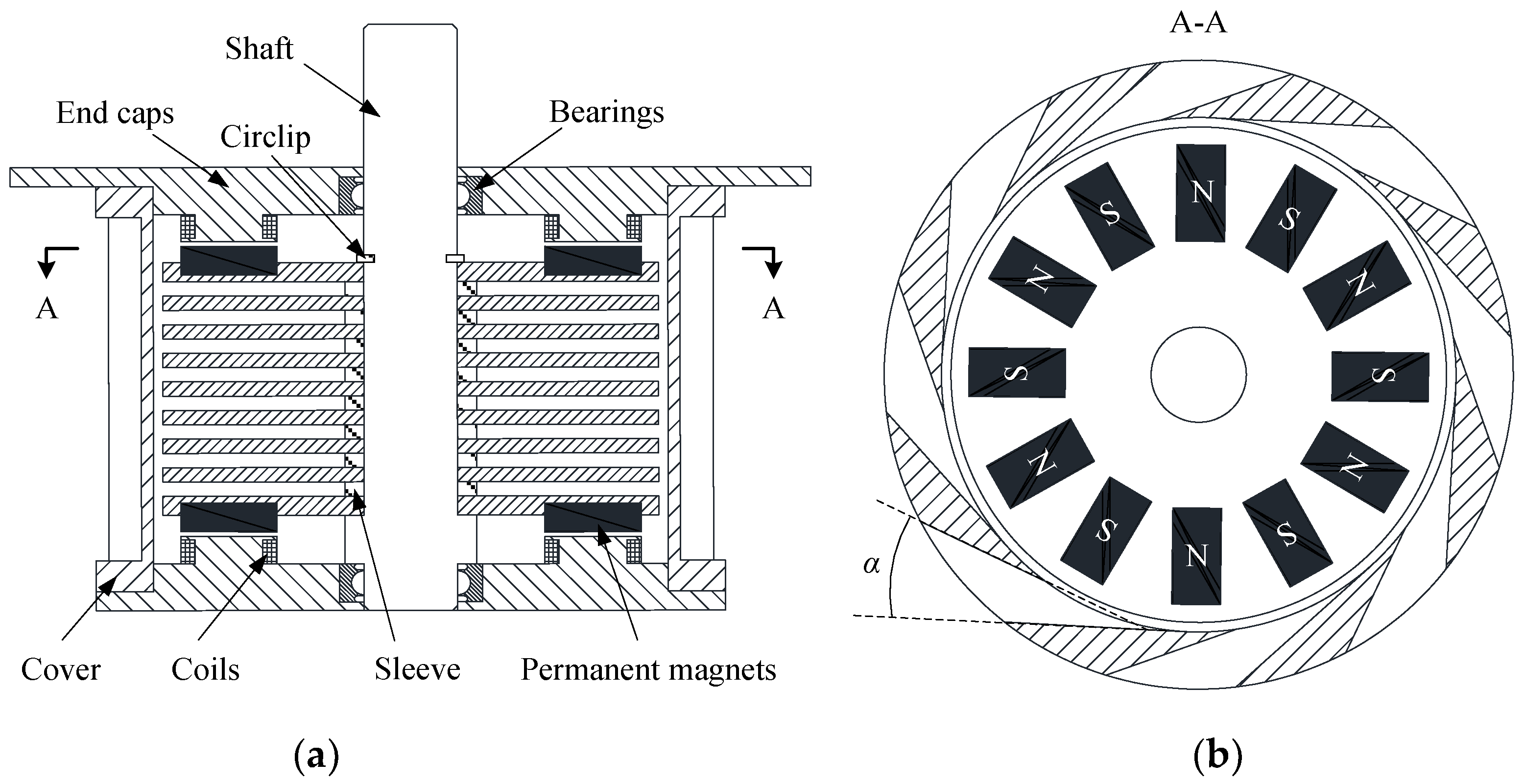
Figure 2.
Photographs of flow energy harvester prototypes: (a) An assembled prototype; (b) Coils fixed in the end cap; (c) Permanent magnets mounted on the disk.
Figure 2.
Photographs of flow energy harvester prototypes: (a) An assembled prototype; (b) Coils fixed in the end cap; (c) Permanent magnets mounted on the disk.

Figure 3.
Dimensions for calculation of magnetic flux density at point (x, y, z).

Figure 4.
Flux density calculated by finite element method (FEM) and analytical model through the coils at the radius of 14 mm.
Figure 4.
Flux density calculated by finite element method (FEM) and analytical model through the coils at the radius of 14 mm.

Figure 5.
Flux density calculated by FEM and analytical model through the coils at the radius of 19 mm.
Figure 5.
Flux density calculated by FEM and analytical model through the coils at the radius of 19 mm.

Figure 6.
Flux density calculated by FEM and analytical model through the coils at the radius of 24 mm.
Figure 6.
Flux density calculated by FEM and analytical model through the coils at the radius of 24 mm.

Figure 7.
Magnitude of magnetic flux through coils varying with dimensional parameters.
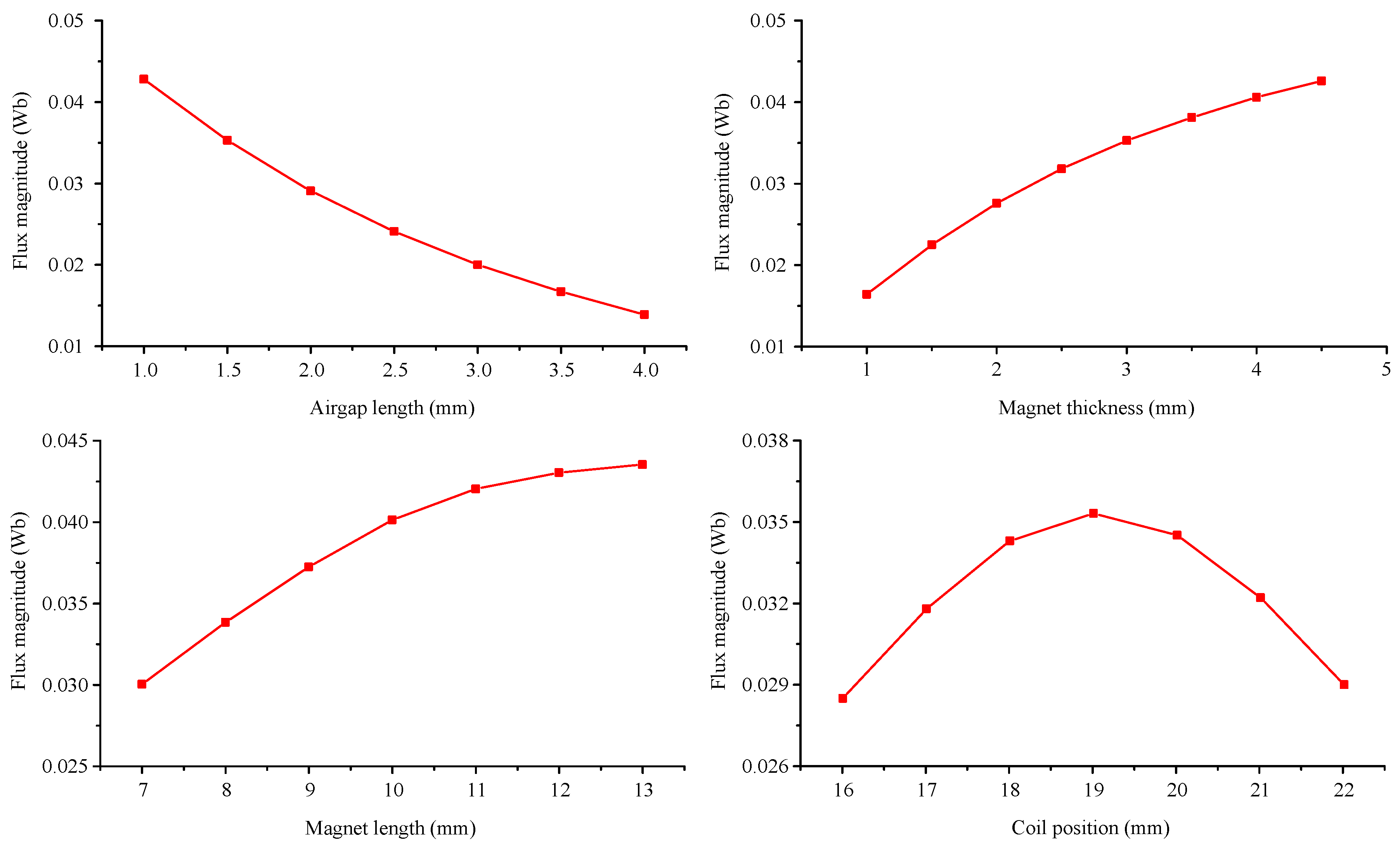
Figure 8.
Schematic of experimental setup for flow energy harvester.

Figure 9.
Induced electromotive force of prototypes with different groove angles under no-load condition.
Figure 9.
Induced electromotive force of prototypes with different groove angles under no-load condition.

Figure 10.
Measured and analytical waveforms of induced electromotive force at rotation speed of 500 rpm.
Figure 10.
Measured and analytical waveforms of induced electromotive force at rotation speed of 500 rpm.

Figure 11.
Measured and analytical peak-to-peak values of induced electromotive force varying with rotation speed.
Figure 11.
Measured and analytical peak-to-peak values of induced electromotive force varying with rotation speed.

Figure 12.
Experimental and analytical results of output voltage varying with load resistance.

Figure 13.
Experimental and analytical results of output electrical power varying with load resistance.
Figure 13.
Experimental and analytical results of output electrical power varying with load resistance.


Table 1.
Main parameters of the prototypes.
| Name | Value | Unit |
|---|---|---|
| Outer diameter | 65 | mm |
| Total height | 46 | mm |
| Total weight | 140 | G |
| Disk number | 8 | - |
| Disk thickness | 1.5 | mm |
| Sleeve thickness | 1.5 | mm |
| Magnet residual flux density | 1.25 | T |
| Magnet relative permeability | 1.06 | - |
| Total magnet number | 24 | - |
| Magnet thickness | 3 | mm |
| Magnet length | 10 | mm |
| Magnet width | 5 | mm |
| Magnet position radius | 19 | mm |
| Total coil number | 24 | - |
| Turn number per coil | 200 | - |
| Airgap length | 1.5 | mm |
| Copper wire diameter | 0.1 | mm |
| Groove number | 8 | - |
| Total coil resistance | 380 | Ω |
© 2018 by the authors. Licensee MDPI, Basel, Switzerland. This article is an open access article distributed under the terms and conditions of the Creative Commons Attribution (CC BY) license (http://creativecommons.org/licenses/by/4.0/).
Share and Cite
MDPI and ACS Style
Wang, T.; Zhang, Y. Design, Analysis, and Evaluation of a Compact Electromagnetic Energy Harvester from Water Flow for Remote Sensors. Energies 2018, 11, 1424. https://doi.org/10.3390/en11061424
AMA Style
Wang T, Zhang Y. Design, Analysis, and Evaluation of a Compact Electromagnetic Energy Harvester from Water Flow for Remote Sensors. Energies. 2018; 11(6):1424. https://doi.org/10.3390/en11061424
Chicago/Turabian StyleWang, Tao, and Yunce Zhang. 2018. "Design, Analysis, and Evaluation of a Compact Electromagnetic Energy Harvester from Water Flow for Remote Sensors" Energies 11, no. 6: 1424. https://doi.org/10.3390/en11061424
Note that from the first issue of 2016, this journal uses article numbers instead of page numbers. See further details here.