Article

Thermodynamic, Economic and Environmental Evaluation of an Improved Ventilation Air Methane-Based Hot Air Power Cycle Integrated with a De-Carbonization Oxy-Coal Combustion Power Plant

National Thermal Power Engineering and Technology Research Center, North China Electric Power University, Beijing 102206, China
*
Author to whom correspondence should be addressed.
Energies 2018, 11(6), 1434; https://doi.org/10.3390/en11061434
Submission received: 4 May 2018 / Revised: 20 May 2018 / Accepted: 21 May 2018 / Published: 4 June 2018
(This article belongs to the Section F: Electrical Engineering)

Abstract

:
Efficient utilization of ventilation air methane (VAM) as well as improving the energy efficiency of de-carbonization oxy-coal combustion power plants are intensively studied for achieving energy savings and greenhouse gas (GHG) emission control. Here, an improved VAM-coal hybrid power generation system, which integrates a VAM-based hot air power cycle with a de-carbonization oxy-coal combustion circulating fluid bed (CFB) power plant was proposed. In the proposed system, part of the boiler flue gas was bypassed to feed the VAM auto-oxidation, and the whole VAM oxidation heat was efficiently utilized to drive a hot air power cycle. Meanwhile, the turbine exhaust air was utilized to heat the feed/condensed water within the regenerative heating trains in a cascade way, which was in turn beneficial to de-carbonization oxy-coal combustion plant. The mass and energy balance of the proposed system were determined using the simulation process. The thermodynamic benefits, economic viability and the environmental impacts were discussed. Results showed that energy efficiency of the proposed system reached 27.1% with the energy saving ratio at 0.9%. The cost of electricity (COE) was $118.15/MWh with the specific CO2 emission as low as 17.46 kg CO2/MWh.

1. Introduction

Global warming has observably affected the natural environment and human activities, making it urgent to decouple greenhouse gas (GHG) emissions from energy-related economic growth. As a primary energy feedstock, coal, feeding ~40% of the world power demand [1], whilst contributing ~45% of the global CO2 emissions [2] and ~14% of CH4 emissions [3,4], has been considered as one of the largest contributors to global warming and environmental pollution. Therefore, it is important to lessen the GHGs emission during the coal mining and utilization process by efficiently and economically capturing or converting the produced GHGs as well as enhancing the coal-based power generation efficiency.
Ventilation air methane (VAM), which is released from mine ventilation shafts, features low-CH4 concentrations in the range of 0.1–1.0 vol.% and contributes ~64% of worldwide coal mine methane emissions [5]. Although VAM contains low concentrations of CH4, the huge quantities and largish global warming potential (GWP) index of CH4 (~25 times greater than CO2 [6]) make it necessary to mitigate VAM emissions, mostly through oxidizing the CH4 into CO2 and H2O. Currently, VAM utilization can generally be divided into ancillary use and principal use patterns [5]. The former mainly refers to using VAM to substitute the ambient air in various combustion processes, such as using VAM as combustion air for in-situ coal-fired power plants, although he variation of the methane concentration and the fluctuating volume of VAM might increase the complexity of boiler combustion or even result in slagging and fouling problems when the control is insufficient [7]. The principal use of VAM mainly refers to combusting/oxidizing it as the primary fuel and utilizing the caloric value of VAM to sustain the oxidation process, and as CH4 concertation is above 0.4 vol.%, part of the oxidation heat can be used to run a steam Rankine cycle for power generation [8]. For example, the West Cliff mine VAM Project in Australia oxidized 250,000 m3/h of VAM with 0.9 vol.% CH4 concentration and simultaneously produced ~6 MW of electric power [8]. However, the parameters of the adopted steam Rankine cycle are relatively low, normally below critical point of water/steam, due to the scale limitation. It seem that there are two alternatives to improve the VAM-based power generation process when the VAM is utilized as a primary fuel. One is to try the best to enhance the amount of available heat released from the oxidation process to feed the power cycle; the other is to select a more suitable power cycle to efficiently utilize the high-temperature heat released from the oxidation process. Hence, if a more suitable external heat source could serve to sustain a steady state VAM oxidation process, the whole oxidation heat/product can be utilized externally for power generation. Moreover, considering the non-corrosive compositions of VAM oxidation product (extremely lean-gas, termed as air hereafter), directly using the compressed hot air as the working medium to expand in an air turbine may be a choice to enhance the power cycle parameters by avoiding the heating transfer temperature difference between the heat source and the working medium.
It is also worth noting that, capturing the CO2 emitted from coal-fired power plants with less energy penalty seems to be an eternal pursuit [9]. Application of the oxy-fuel combustion circulating fluidized bed (CFB) is considered as one of the most promising technologies, given: (1) its high heat and mass transfer rates as a result of vigorous gas-solid mixing as well as sufficiently large volume throughput; (2) less pollutant emissions (NOX and SOx) owing to a lower operating temperature; and (3) relative low efficiency penalty due to a high CO2 concentration with the boiler flue gas [10,11,12]. However, there still exists a 10–12 percentage points efficiency penalty compared with the plant without CO2 capture [13], because of the huge power consumption in the air separation unit (ASU) and CO2 multi-stage compressors with intercooler trains. Many researchers have proposed approaches to reduce the efficiency penalty by parameter optimization and system integration. Escudero et al. [14] optimized the parameters of an ASU, compression and purification unit as well as utilized the waste energy in an oxy-fuel combustion CFB power plant through incorporating an improved steam cycle, and concluded that the efficiency penalty could be reduced from 10.5 percentage points to 7.3 percentage points. Kotowicz et al. [15] recovered the waste heat from an ASU, CO2 capture and storage process and flue gas drying device to heat the condensed water within the steam cycle, and the efficiency penalty could be reduced by 3.3 percentage points. The aforementioned studies focused on parameter analyses or system re-configuration within the oxy-fuel combustion plants, while integration of the oxy-fuel combustion plants with other power cycles to synergistically utilize the energy flows have not drawn the attention it deserves. A possible explanation for this neglect of a promising strategy could be a ‘one-plant-one-fuel’ paradigm in the area of power production. Synthetically considering the temperature of the VAM oxidation and the boiler flue gas at the cyclones (800–900 °C) [16], it seems that the boiler flue gas has the potential to serve as a suitable heat source for sustaining the VAM oxidation, and simultaneously, the cold-end energy released from the VAM utilization process can also be efficiently utilized in the host oxy-coal combustion power plant.
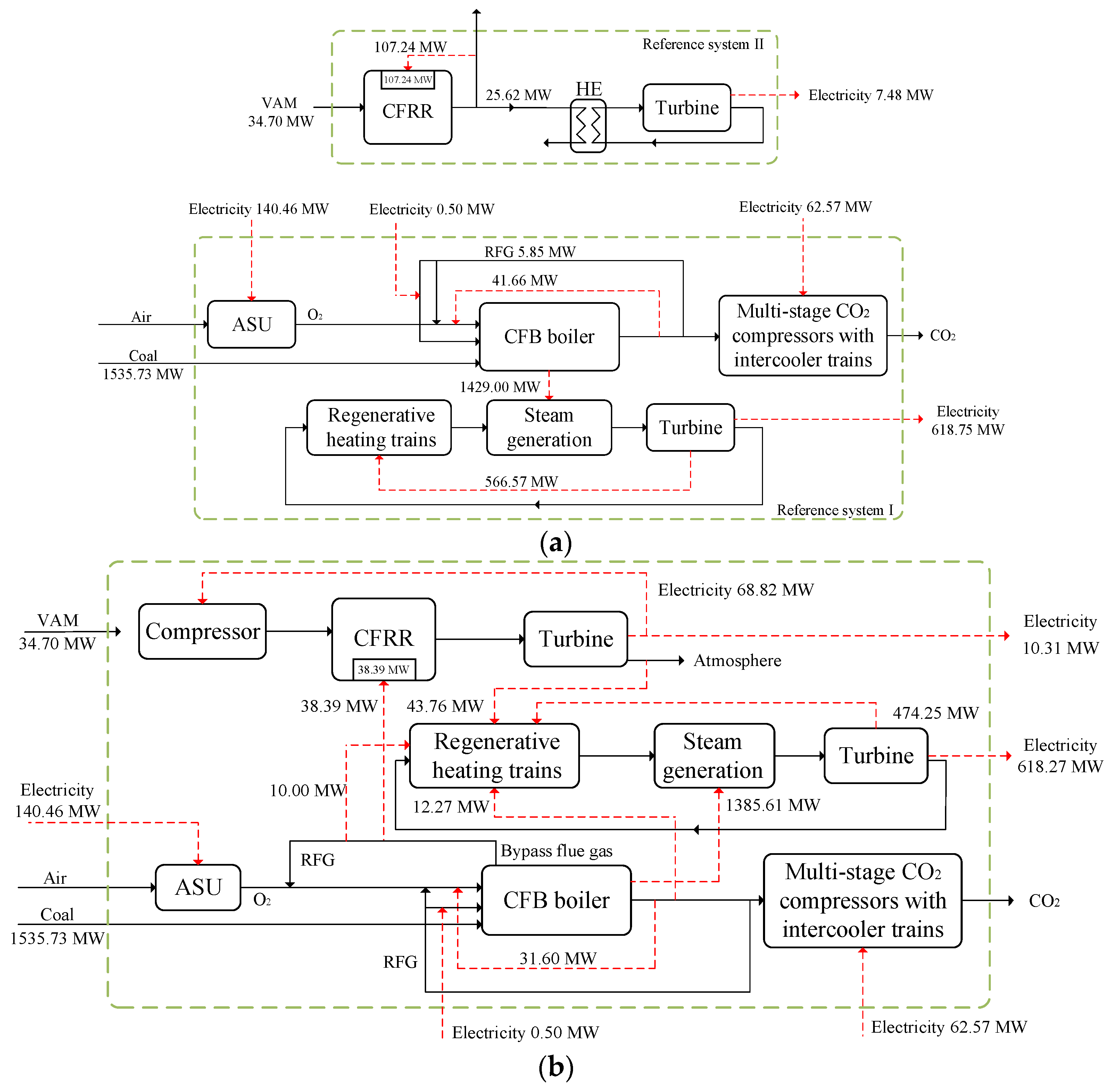
Against this backdrop, in this work an innovative VAM-based hot air power cycle integrated with a de-carbonization oxy-coal combustion power plant was proposed, to efficiently utilize the VAM caloric value for power generation and increase the overall power generating efficiency by cascade utilization of the cold-end energies from both the CFB boiler and hot air power cycle. The mass and energy balance of the proposed system in conjunction with a 600 MW electric power plant was computed through the system simulation and the overall system thermodynamic performance were determined and compared with two standalone reference systems. The economic viability were determined by calculation the cost of the electricity (COE) and the mitigated equivalent CO2 (CO2-eq) emission and specific CO2 emission were selected as the metrics for evaluating the environmental performance of the proposed system. The influence of methane concentration and VAM compression ratio on the energy/temperature distributions and system performance were also discussed.

2. System Proposal

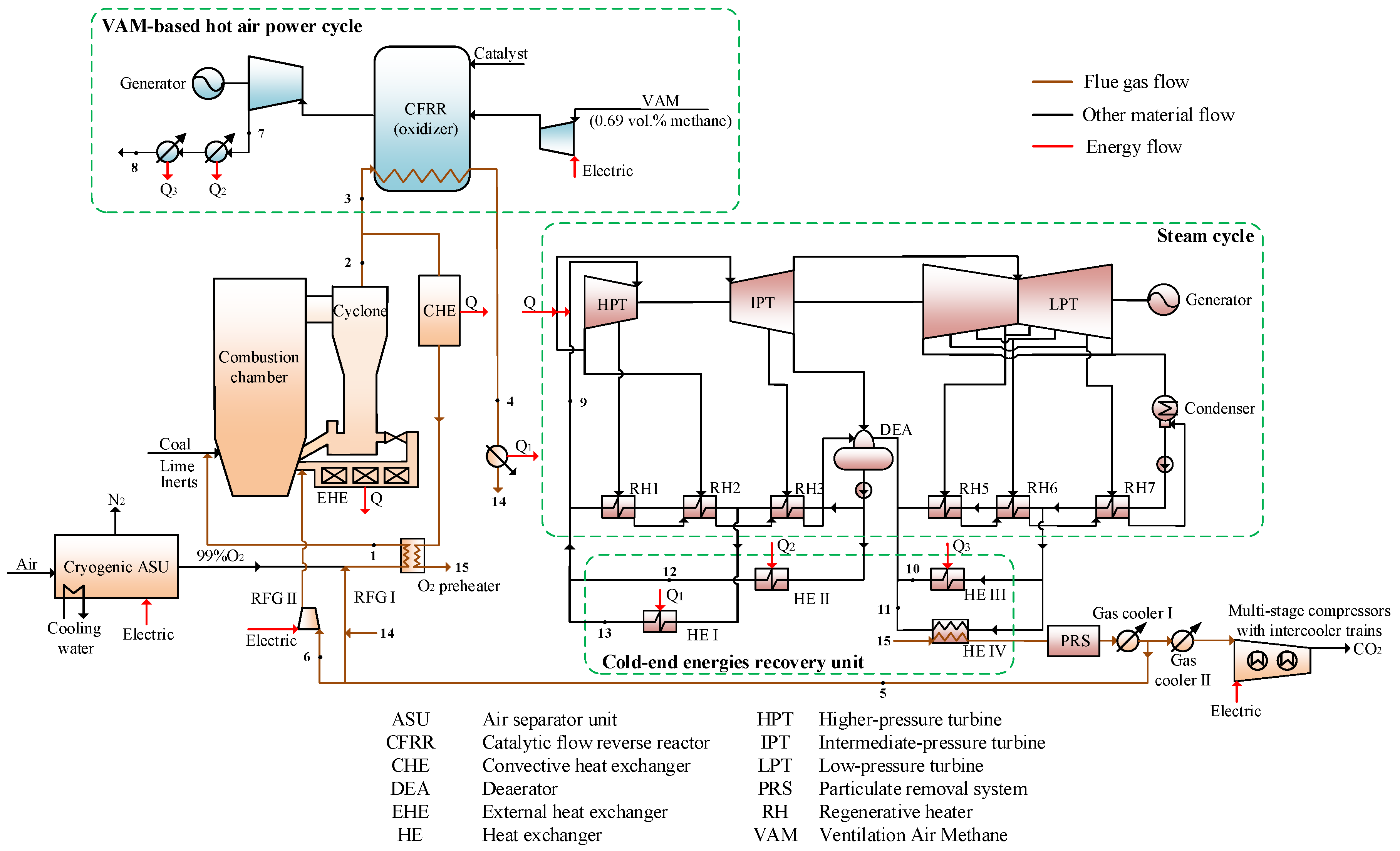
Figure 1 schematically shows the process of a VAM-based hot air power cycle integrated with a de-carbonization oxy-coal combustion CFB power plant. The proposed system consists of four sub-units: (1) a de-carbonization oxy-coal combustion CFB boiler with bypass flue arrangement; (2) a VAM-based hot air power cycle; (3) a steam cycle and (4) a cold-end energies recovery unit.
Different from the conventional CFB boiler, the flue gas leaving the cyclones is divided into two streams. The bypassed flue gas (stream 3) releases heat within the oxidizer to sustain the VAM auto-oxidation and the remaining major part of the flue gas (main flue gas) enters the convection heat exchanger (CHE) to heat the steam cycle. Obviously, less convective heat can be absorbed by the steam cycle, as the mass flowrate of the feed coal is as same as the CFB boiler without bypass flue configuration.
Comparing with the conventional VAM oxidation and utilization process incorporating a steam Rankine cycle, the VAM is firstly pressurized, increasing the temperature and pressure prior to the oxidizer. In the oxidizer, the oxidation product (the hot and compressed air) directly flows into an air turbine, expanding to produce work. This proposed VAM power generation process is termed as VAM-based hot air power cycle. Clearly, this process has higher parameters of the working medium and the corresponding higher exhaust air temperature than the conventional process. The energy of the exhaust air from air turbine can be beneficially recovered in the host oxy-coal power plant by heating the feed/condensed water, saving a portion of the steam bleeds, which can then expand in the following stages of the turbines to boost the electric power output.
Obviously, the proposed system has the potential to improve the VAM oxidation and utilization process, while the heat reclamation and re-distribution within the hot air power cycle and the de-carbonization oxy-coal power plant may also enhance the efficiency of the overall power generation process.

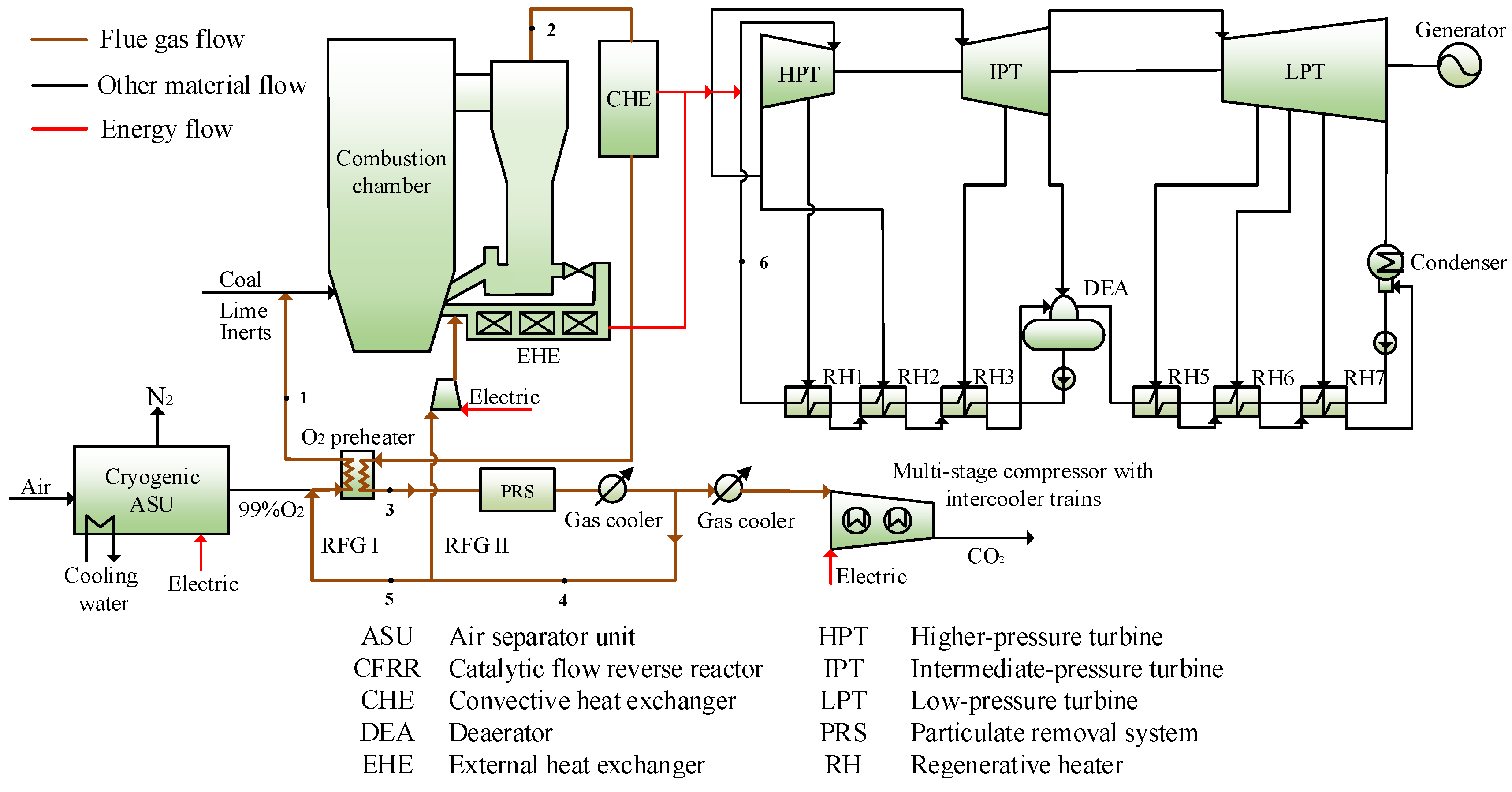
2.1. De-Carbonization Oxy-Coal Combustion CFB Boiler with Bypass Flue Arrangement

By using cryogenic distillation technology, 99.0 vol.% purity O2 is produced within the ASU, mixed with recirculated flue gas I (RFG I) and is then heated in the O2 preheater to 281.0 °C. At the cyclones outlet, part of the boiler flue gas (stream 3) with 871.0 °C is bypassed to sustain the VAM oxidation and the rest is cooled down to 308.0 °C within CHE to convectively heat the steam cycle and is further cooled down to 157.2 °C in the O2 preheater. The flue gas at gas cooler I outlet with 74.0 °C is divided into two streams, part of flue gas (stream 5) is sent back as RFG, and the rest is further cooled down to 40.0 °C, compressed in multi-stage compressors with intercooler trains for transport and storage.
The proximate and ultimate analyses of the used coal are listed in Table 1. The mass flowrate of the coal is set at 60.06 kg/s, the combustion efficiency of the CFB boiler is 99.0% and the boiler efficiency is estimated at 90.0% after considering the coal components and CFB boiler miscellaneous losses [16].

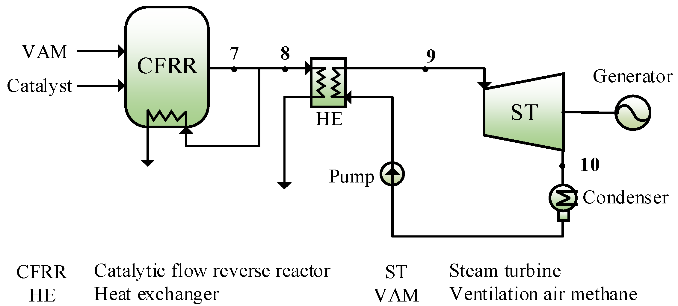
2.2. VAM-Based Hot Air Power Cycle

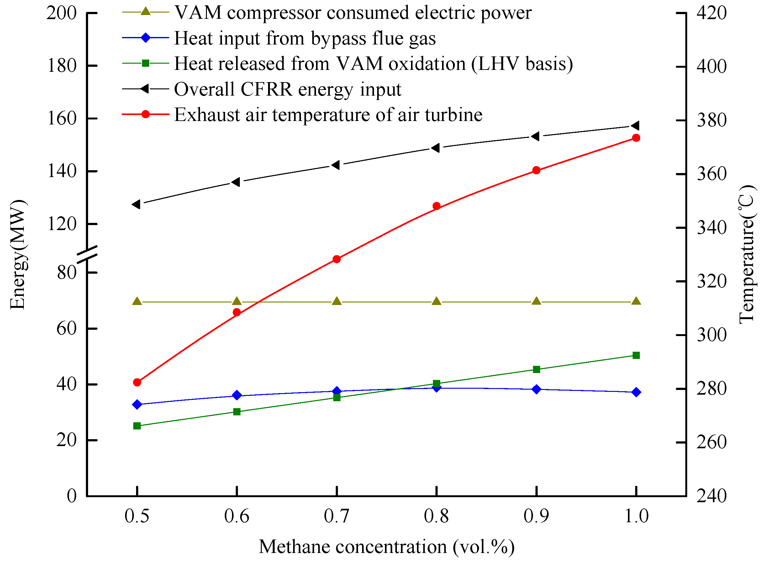
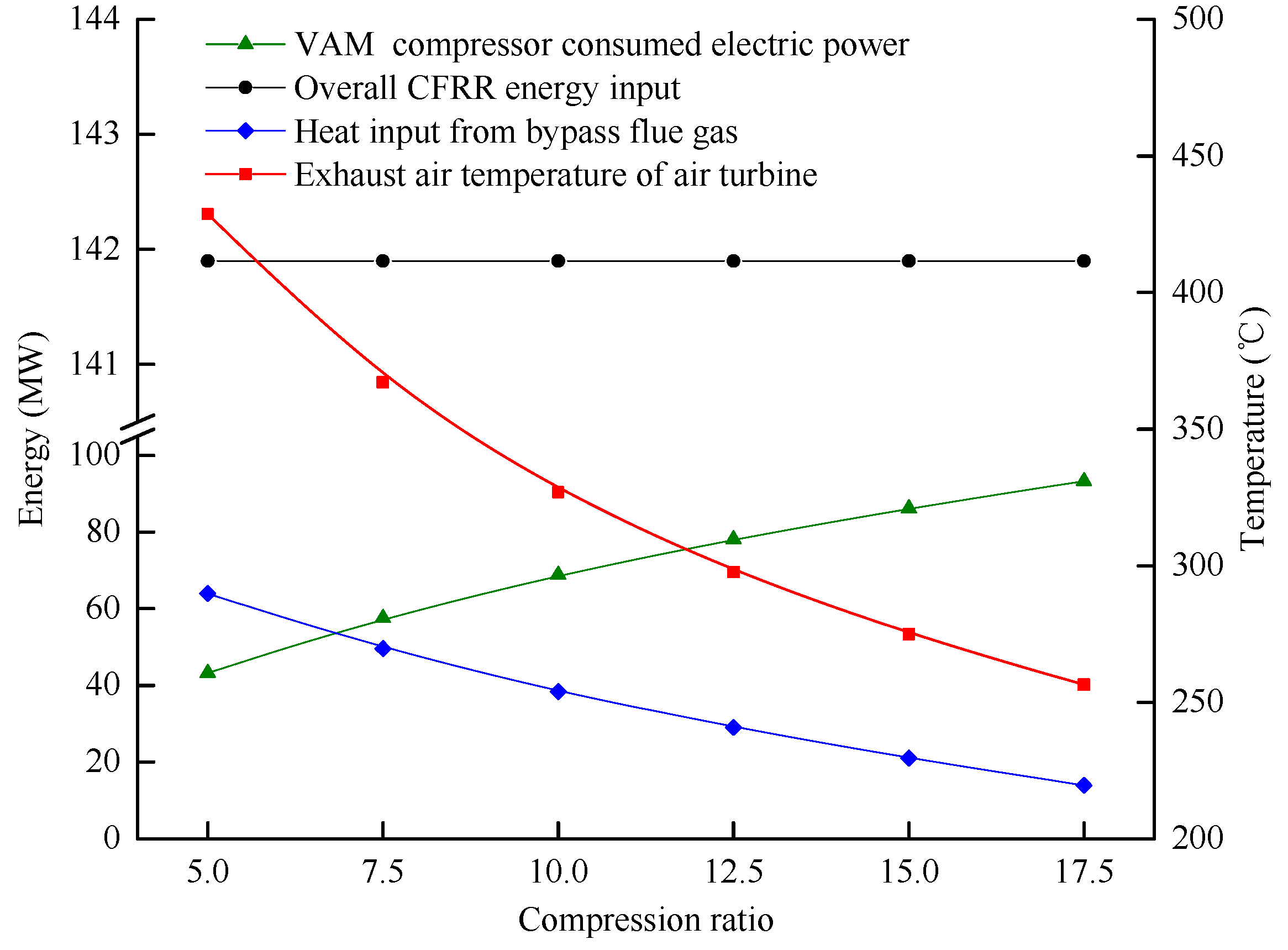
In the proposed system, a catalytic flow reversal reactor (CFRR) is adopted, which can oxidize VAM with methane concentrations as low as 0.1 vol.% and requires a relatively low methane auto-ignition temperature due to the adoption of catalyst. The mass flowrate of the feed VAM (0.10 MPa, 20.0 °C) is set at 180.00 kg/s. The methane concentration is 0.69 vol.% with the corresponding methane auto-ignition temperature at 500.0 °C and the CFRR outlet hot air temperature at 728.0 °C [17]. The pressure of VAM at the compressor outlet is designed at 1.00 MPa and the back pressure of the air turbine is set at 0.10 MPa.

2.3. Steam Cycle and Cold-End Energies Recovery

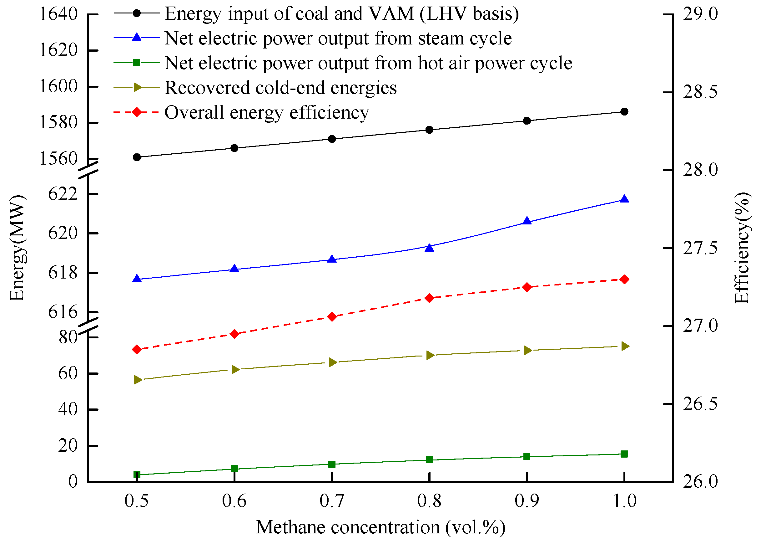
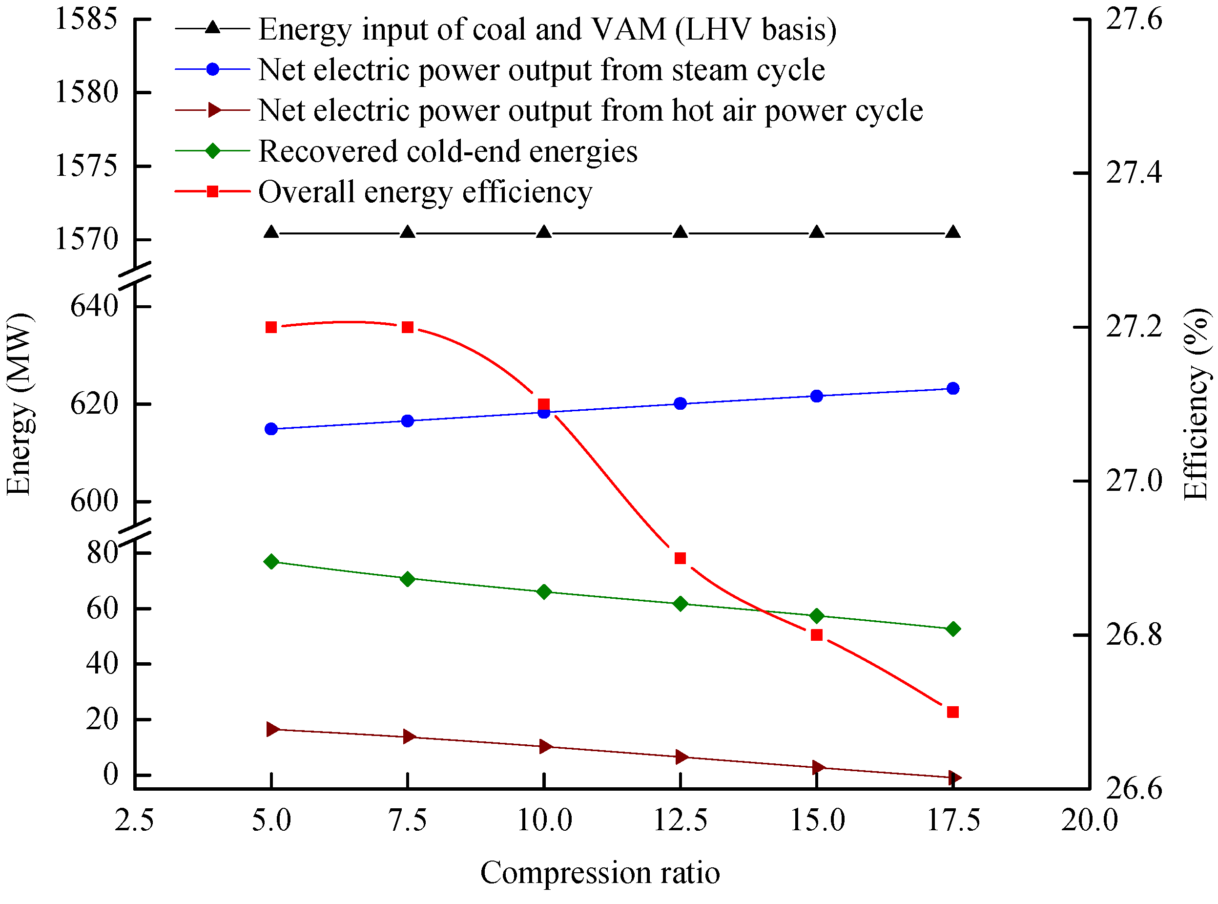
A typical 600 MW electric power plant with the live/reheat steam of 16.67/3.41 MPa and 538.0/538.0 °C is selected here, which comprises of a high-pressure turbine (HPT), an intermediate-pressure turbine (IPT), and a low-pressure turbine (LPT). The parameters of the regenerative heaters (RHs) (including three stages for the condensed water, three stages for the feed-water, and one deaerator (DEA)) are listed in Table 2, taken from the design data of the Midong power plant in Xinjiang, China. After absorbing heat in boiler furnace, CHE and external heat exchanger (EHE), the live steam is delivered to HPT and then flows into IPT and LPT in sequence to produce work. The exhaust steam from the LPT is condensed to liquid at 0.02 MPa and 54.0 °C. Four stages of gas/air-water heat exchangers (HE I–IV) are arranged paralleled to series of RHs to heat the feed/condensed water to the designed temperature, saving a portion of steam bleeds of 1st, 2nd, 3rd, 5th and 6th regenerative heaters, respectively.

3. System Simulation and Evaluation Criteria

3.1. Reference Systems Description

The proposed system can be considered as a coal-VAM hybrid power generation system, and as such, two standalone power generation systems, i.e., a conventional de-carbonization oxy-coal combustion CFB power plant and a conventional VAM-based power generation process, are selected as reference systems to quantify the thermodynamic benefits brought from system integration.
Figure 2 describes the configuration of the conventional de-carbonization oxy-coal power plant (reference system I), which is adopted from [16]. In this system, the mass flowrate of the coal, the temperature of the mixture of hot O2 and RFG I (stream 1), the temperature of boiler flue gas at the cyclones outlet (stream 2), the parameters of live steam and reheat steam within the steam cycle, and the parameters of captured CO2 are same as those in the proposed system. While, there is no cold-end energies recovery unit in the reference system I and the exhaust flue gas (stream 3) with the temperature of 157.2 °C is cooled down to 74.0 °C and then is split into two streams. One stream (stream 4) is sent back as RFG, the rest is further cooled and sent to CO2 capture device.
Figure 3 describes the configuration of the conventional VAM-based power generation system incorporating a steam Rankine cycle (reference system II), which is adopted from [18]. In this system, part of the hot air (stream 8) is utilized to drive a subcritical steam Rankine cycle with the live steam parameters at 4.00 MPa/450.0 °C and back pressure at 0.02 MPa. The CH4 concertation, mass flowrate of the VAM and temperature of the hot air (stream 7) in the reference system II are same as those of in the proposed system.

3.2. System Simulation

Thermodynamic parameters and system performance for these three systems were simulated by the EBSILON Professional software, which is specialized in power generation fields and is used to design, simulate and optimize thermodynamic cycle processes [19,20]. For the adopted models: (1) “Combustion chamber with heat output” block is chosen for modelling the CFB boiler and the CFRR; (2) all kinds of turbines and compressors are simulated by the modules “turbines” and “compressor”, respectively, which allow different working medium composition input and settings of isentropic efficiencies; (3) for different types of heat exchangers, “Air preheater” module is chosen for simulating the O2 preheater and the heat exchangers embedded within the CFRR; (4) modules “Feed water preheater”, “After-cooler” and “Deaerator” are chosen for modelling the conventional regenerative heating trains; and (5) the heat exchangers in the cold-end energies recovery are simulated by the module “Universal heat exchanger”. Some more detailed information for systems simulation are listed in Table 3.
To verify the reliability of the simulation results, the CFB boiler without bypass flue and steam cycle without heat recovery are simulated first. Results shows that the simulated heat throughput of the CFB boiler and the corresponding electric power output of steam cycle are highly agreed with the designed data in the literature [16] and the selected plant, with the relative deviation at 1.1% and 1.4%, respectively.
Given the system configuration, initial conditions and main assumptions, the mass flowrate of the bypass flue in the proposed system, required recycled air in the reference II, the live steam of steam cycle, and the mass flowrate of feed/condensed water heated within cold-end energies recovery unit in the proposed system can be computed. The corresponding energy distribution characteristics can also be determined.

3.3. Evaluation Criteria

In this section, system performance from the perspectives of thermodynamics and environmental impacts are determined. Economic evaluation for assessing the feasibility of this integrated system was also conducted.

3.3.1. Criteria for Thermodynamic Evaluation

The integrated concept is a coal-VAM hybrid power generation system, considering the fact that the exergy and electricity of the fuel (coal and VAM) are nearly equal to their embodied energies, and thus, the exergy efficiency of the system is nearly equal to its energy efficiency. Here, the net energy efficiency is taken as the sole basic criteria to assess the system thermodynamic performance, which is defined as:
η net = P Q in = P VAM + P coal Σ P i m coal LHV coal   +   m VAM LHV VAM   ,
where P denotes the electric power output (MW) of the overall system; Qin is the input energy (MW); PVAM is the electric power output (MW) from the VAM-based power generation system; Pcoal is the electric power output (MW) from the oxy-coal power plant; ∑Pi is the cumulative auxiliary power consumptions (MW) of ASU, CO2 multi compression process and RFG induced fan; m and LHV are the mass flowrate (kg/s) and lower heating value (MJ/kg), respectively.
Moreover, energy saving ratio (ESR) is also adopted here to assess the degree of fuel saving effects brought from the system integration and energy reclamation, and can be presented as the following:
ESR = Δ Q in Q in - ref = ( P I / η net - I + P II / η net - II ) ( P P / η net - P ) P I / η net - I + P II / η net - II ,
where ΔQin denotes the less amount of energy input (MW) of the proposed system as compared with the two reference systems with the same electric power throughput; Qin-ref denotes the energy input (MW) of the reference systems; and subscripts I, II and P presents the reference system I, reference system II and the proposed system, respectively.

3.3.2. Criteria for Economic Evaluation

To further assess the economic viability of the proposed system, the cost of electricity of the proposed is determined and compared with the reference system I, using the following [24]:
COE = FC L + CC L + OMC L P N w ,
where FCL, CCL and OMCL represent the values of annual fuel costs ($/year), annual carrying charges ($/year), and annual operating and maintenance costs ($/year), respectively; N indicates the number of hours of plant operation per year (h/year), and w represents the average capacity factor. The major assumptions for COE calculation are listed in Table 4.
Noting that, to calculate the fuel cost, only the coal’s fee is considered, considering VAM with low-energy density is normally discharged as waste during the coal mining process if no special device is adopted to use it, and thus, the FCL is calculated by:
FC L = 3.6 m coal LHV N w p coal ,
where pcoal denotes the coal price ($/MJ), on LHV basis.
The CCL is calculated according to Equation (5):
CC L = CRF FCI ( 1 + α ) ,
where the capital recovery factor (CRF) is related to the discounted rate (k) and the life of equipment (n), calculated by CRF = [ k ( 1 + k ) n ] / [ ( 1 + k ) n 1 ] ; FCI is the fixed capital investment (M$) of the plant; and α is the compound interest rate during construction.
The FCI includes the purchased equipment costs, installation and engineering expenditures and the process and project contingency costs. For proposed system, the total FCI can be obtained by: FCItot = FCIunit-I + FCIunit-II + FCIunit-III + FCIunit-IV. For the reference system I, the total FCI includes the FCI of the CFB boiler, steam turbines generation unit and CO2 multi compression process, calculated by FCItot = FCIboiler + FCIST + FCIcom.
The specific FCI is computed based on the scaling up method as [29]:
FCI = FCI 0 ( S S 0 ) f ,
where FCI0 is the fixed capital cost of a reference component at size S0, FCI is the fixed capital cost of the component at size S, and f is scaling factor. The detailed information relating to the specific FCI calculation are shown in Table 5.

3.3.3. GHG Mitigation Effects

The GWP of CH4 is 25 greater than CO2 [6], meaning that the degree of the CH4 impacts on the global warming is more serious. In the proposed system, the VAM-based hot air power cycle lessens the CH4 footprints by oxidizing the CH4 within VAM into CO2 and H2O, while producing additional CO2 emissions, which is directly discharged into ambient. Meanwhile, most part of the CO2 generated from the coal combustion is captured. To synthetically assess GHG mitigation effects of the proposed system, the avoid equivalent CO2 emission is calculated, which consider both the quantities and the GWP of the GHG, presented by:
Δ m CO 2 - eq = m CO 2 - coal ζ + m CH 4 GWP CH 4 M CO 2 M CH 4 m CH 4 ,
where the m CO 2 - coal is the mass flowrate (kg/s) of CO2 generated from coal combustion; ζ is the CO2 capture ratio of de-carbonization power plant; m CH 4 is the mass flowrate (kg/s) of CH4 within the VAM; MCO2 and MCH4 are the relative molecular mass of CO2 and CH4, respectively.
The specific CO2 emission (kg-CO2/MWh) is also adopted here to assess the system GHGs emission intensity, defined as:
m CO 2 - S = Δ m CO 2 P P = m CO 2 - coal ( 1 ζ ) + M CO 2 / M CH 4 m CH 4 P P ,
where Δ m CO 2 denotes the mass flowrate (kg/s) of the CO2 emissions discharged to the ambient.

4. Results and Discussions

4.1. Thermodynamic Performance

Based on the system simulation, Table 6 and Table 7 present the main parameters of those three systems. Thermodynamic performance of the proposed system is also compared with the reference systems in Table 8, with the following observations: (1) 58.90 kg/s of boiler flue gas is bypassed to CFRR and is cooled down to 379.2 °C, releasing 38.39 MW heat; (2) in the cold-end energies recovery unit, 201.91 kg/s of feed/condensed water can be heated to the designed point as same as the reference system I. To be specific: (i) at the flue gas side, 58.90 kg/s of bypass flue gas with 379.2 °C heats 33.00 kg/s feed-water in HE I and returns as part of RFG I at 235.5 °C; (ii) 180.00 kg/s of exhaust air from air turbine with 326.9 °C heats 59.6 kg/s of feed-water in HE II and 65.20 kg/s of condensed water in HE III in sequence; and (iii) 184.48 kg/s of exhaust flue gas at O2 preheater downstream at 157.2 °C heats 44.11 kg/s of condensed water in HE IV; (3) after considering 203.53 MW of auxiliary power consumption, 425.05 MW of net electric power is obtained in the proposed system, which is 2.35 MW higher than the sum of two standalone systems; (4) the overall system efficiency is 27.1%, which is 0.1%-points and 5.5%-points higher than that of reference systems, respectively, meaning that the proposed system has huge improvement on VAM oxidation and utilization process, whilst incorporating hot air power cycle does not affect the oxy-coal power plant performance; and (5) the ESR is 0.9%, meaning that the energy embodied within 0.14 t/h coal or 244.80 t/h VAM can be saved if the electric power throughput is the same as the reference systems.
To further reveal the benefits brought from the system synthesis and integration, the energy distribution characteristics of the proposed system are compared with the reference systems, which are shown in Figure 4. It is obvious that the intensive energy reclamations within the bypass flue, VAM-based hot air power cycle and regenerative heating trains are unique characteristics in the proposed system. Several key points can be noted: (1) in the proposed system, 38.39 MW of flue gas sensible heat and 68.82 MW heat from VAM compressor are used to sustain the VAM auto oxidation (107.21 MW), which is otherwise supplied by recirculated oxidation product; (2) through utilizing the heat released by the bypass flue gas, 10.31 MW of electric power is produced by the hot air power cycle, which is 2.83 MW greater than that of reference system II; and (3) the heat for steam generation in the proposed system is 43.39 MW less than that of reference system I, while 66.03 MW (43.76 MW + 12.27 MW + 10.00 MW) of heat from the air turbine cold-end, CFB boiler cold-end and bypass flue gas is recovered and injected into the regenerative heating trains, and finally, 618.27 MW of net electric power is produced from steam turbine generation unit. To sum up, the proposed coal-VAM hybrid power generation system features better thermodynamic performance as compared to the reference systems, mainly owing to the efficient integration of the VAM-based hot air power cycle with the host oxy-coal power plant.

4.2. Economic Viability and Environmental Impact

The specific FCI of the required unit and the COE of proposed system is computed and compared with the host oxy-coal power plant (reference system I), with the results shown in Table 9. As can be seen, the FCI of the proposed system is $73.20 M higher than the reference system I, and correspondingly increase the CCL and the OMCL by 10.8%-points and 10.8%-points, respectively. Although the net electric power output increases from 415.22 MW to 425.05 MW, the COE of proposed system still slightly increase by 3.1%-points comparing with the host plant. The slight increase of the COE seems to be acceptable, because that the energy density of the VAM is quite low and the VAM utilization process is inevitably less efficient than the coal utilization process. More importantly, from the perspective from the GHG mitigation, the proposed system can avoid 147.75 kg/s of CO2-eq emissions with the specific CO2 emission as low 17.46 kg CO2/MWh. In other words, the proposed system can mitigate ~3.6 million tons of CO2-eq emissions per annum.

4.3. Sensitivity Analysis

Methane concentration and VAM compression ratio are two main factors within the VAM-based hot air power cycle, which have influence on the overall system energy distribution and thermodynamic performance. Therefore, sensitivity analyses are adopted here to discuss the effects of these two factors on the proposed system performance, given the mass flow rates of feed coal, the temperature difference of VAM preheater within CFRR and temperature of exhaust flue gas from boiler are unchanged.

4.3.1. Methane Concentration in VAM

Clearly, once the methane concentration within the VAM is determined, the VAM caloric value, energy required for sustaining the VAM oxidation, and the corresponding temperature of the hot air at CFRR outlet are determined too. Due to the fact that the methane concentration in VAM always fluctuates during the coal mining process, the energy/temperature distributions within the VAM oxidation and utilization process will change, sequentially changing the amount of energy supplied by boiler flue gas for VAM oxidation, the available heat from VAM oxidation for power generation, and the amount of recoverable cold-end energies. In this section, the influence of the methane concentration (variation between 0.4 and 1.0 vol.%) is discussed while the pressure at CFRR inlet is unchanged at 1.0 MPa.
Figure 5 shows the energy/temperature distributions within the hot air power cycle in response to the methane concentration variation. It can be found that: (1) the exhaust air temperature increases as the methane concentration increases, due to the fixed compression ratio and the increased hot air temperature at CFRR outlet as a result of the greater energy density of the VAM. The value of the temperature of hot air at CFRR outlet in different methane concentration are taken from the Ref. [17]; (2) CFRR energy input, including the VAM caloric value input, VAM compressor energy input, and heat from bypass flue gas, reaches 157.28 MW as the methane concentration is 1.0 vol.%; and (3) VAM caloric value increases linearly as methane concentration increases, while VAM compressor energy input seems stable, and heat released by the bypass flue gas increases with methane concentration until 0.8 vol.% and thereafter it drops. This can be explained that, as the methane concentration is extremely low (below 0.8 vol.%), the majority energy input to CFRR mainly comes from the external heat source (VAM compressor and bypass flue gas) instead of its own caloric value. On the contrary, as the methane concentration exceeds 0.8 vol.%, large part of CFRR energy input comes from the VAM oxidation itself, and correspondingly decreases the required energy from bypass flue gas.
Figure 6 shows the influence of methane concentration on the overall system performance. As the methane concentration increases, the overall energy input and energy efficiency increase as well. For the hot air power cycle, the net electric power output increases as the methane concentration rises, because the inlet and outlet enthalpies of air within the air turbine are both enhanced, while the inlet enthalpy increment is greater under the fixed compression ratio. For the steam cycle, the net electric power throughput increases due to the recoverable energy from the exhaust air increases as the methane concentration rises, especially when the methane concentration is above 0.8 vol.%, less amount of bypass flue gas is required, and correspondingly more heat can be transferred from flue gas to steam cycle for power generation. For example, as the methane concentration rises from 0.5 vol.% to 0.8 vol.%, the electric power output from hot air power cycle increases by 8.35 MW, the amount of cold-end energies recovered increases by 13.61 MW, and the electric power output from steam cycle increased by 1.56 MW, increasing the overall energy efficiency from 26.8% to 27.2%.

4.3.2. VAM Compression Ratio

Apparently, as the methane concentration of VAM is unchanged, the compression ratio also has an influence on the energy distribution of the hot air power cycle, sequentially affecting the whole system performance. In this section, the system performance variation in response to a VAM compression ratio in the range of 5.0–17.5 is discussed. It is also worth to note that the pressure of VAM at CFRR inlet does not affect the temperatures within CFRR while the require external heat would be changed [17].
Figure 7 shows the energy/temperature distributions within the hot air power cycle in response to the compression ratio variation. It can be found that: (1) the overall CFRR energy input is stabilized as the compression ratio increases, due to the constant methane concentration; (2) VAM compressor consumed electric power increases as the compression ratio rises, correspondingly decreasing the heat input from bypass flue gas; and (3) the expansion ratio of air turbine rises as the compression ratio increases, which results in a decline of the exhaust air temperature under the fixed back pressure of air turbine.
Figure 8 shows the influence of compression ratio on the overall system performance. As the compression ratio increases, the overall energy input is stabilized and energy efficiency drops. For the hot air power cycle, the net electric power output decreases as the compression ratio rises, due to fact that the required additional electric power for compressor overweighs the increase of the work output from the air turbine as the CFRR outlet air temperature keeps constant. For the steam cycle, the recovered cold-end energy decreases with the rise of compression ratio, due to the fact that the reduction of the air turbine cold-end energy overweighs the increase of the recoverable heat from CFB boiler cold-end. The electric power throughput enhances with the increase of compression ratio, owing to greater mass flow rate of live steam as a result of a larger flue gas energy feeding the steam cycle. From the perspective from the overall system, it shows a decline tendency for energy efficiency. For example, as the compression ratio rises from 5.0 to 12.5, although net electric power output from steam cycle increases by 5.26 MW, the electric power output from hot air power cycle decreases by 9.93 MW, decreasing the overall energy efficiency from 27.2% to 26.9%.

5. Conclusions

This study revealed that the VAM-based power generation process can be improved by using a hot air power cycle and integration within a oxy-coal power plant. Several meaningful conclusions can be drawn: (1) the overall system efficiency reached 27.1%, better than the standalone reference systems, owing to the utilization of the boiler bypass flue gas to feed the VAM oxidation as well as recovering cold-end energy heat to the regenerative heaters; (2) adoption of the hot air power cycle slightly increased the COE of the integrated system by 3.1%-points compared with the host coal-fired power plant, while the proposed system can avoid ~3.6 million tons of CO2-eq emissions per annum with the specific CO2 emission as low as 17.46 kg CO2/MWh; and (3) the sensitivity analyses revealed that the energy efficiency of the proposed system enhances as the methane concentration rises, while reduces as compression ratio increases. This proposed concept has been shown to provide a thermodynamically preferable and economically viable approach to efficiently utilize the VAM as well as improve the oxy-coal power plant generation efficiency.

Author Contributions

C.X. and Y.G. wrote and revised this paper, Y.G. carried out simulation, conducted calculation. Q.Z. checked the simulation and calculation. G.Z. and G.X. checked the paper and provided financial support.

Acknowledgments

This research was funded by the National Nature Science Fund of China (No. U1610254, No. 51706065), Fundamental Research Funds for the Central Universities (No. 2015ZZD10, No. 2017ZZD003), and the 111 Project (B12034).

Conflicts of Interest

The authors declare no conflict of interest.

Nomenclature

AbbreviationsFull name
ASUAir separation unit
CFBCirculating fluidized bed
CFRRCatalytic flow reversal reactor
CHEConvection heat exchanger
CO2-eqCO2 equivalent
CRFCapital recovery factor
DEADeaerator
EHEExternal heat exchanger
ESREnergy saving ratio
GHGGreenhouse gas
GWPGlobal warming potential
HPTHigh-pressure turbine
IPTIntermediate-pressure turbine
LPTLow-pressure turbine
RFGRecirculated flue gas
RHRegenerative heater
VAMVentilation air methane
SymbolsContent
FCLValues of annual fuel costs ($/year)
CCLAnnual carrying charges ($/year)
OMCLAnnual operating and maintenance costs ($/year)
NNumber of hours of plant operation per year (h/year)
wAverage capacity factor
pfuel price ($/MJ)
CRFcapital recovery factor
kDiscounted rate
nLife of equipment (year)
FCIfixed capital investment of the plant (M$)
αCompound interest rate during construction
SSize of the component
Δ m CO 2 - eq Avoid equivalent CO2 emissions (kg/s)
m CO 2 - S Specific CO2 emission (kg-CO2/MWh)
MRelative molecular mass
ζCO2 capture ratio (%)
SubscriptsContent
inInlet
IReference system I
IIReference system II
PThe proposed system
0Reference component

References

  1. Erdem, H.; Dagdasa, A.; Sevilgena, H.; Cetin, B.; Akkaya, A.; Sahin, B.; Teke, I.; Gungor, C.; Atas, S. Thermodynamic analysis of an existing coal-fired power plant for district heating/cooling application. Appl. Therm. Eng. 2010, 30, 181–187. [Google Scholar] [CrossRef]
  2. IEA Agency. CO2 Emissions from Fuel Combustion Highlights 2017; IEA Agency: Paris, France, 2017. [Google Scholar]
  3. Karakurt, I.; Aydin, G.; Aydiner, K. Mine ventilation air methane as a sustainable energy source. Renew. Sustain. Energy Rev. 2011, 15, 1042–1049. [Google Scholar] [CrossRef]
  4. Gao, H.; Runstedtler, A.; Majeski, A.; Yandon, R.; Zanganeh, K.; Shafeen, A. Reducing the recycle flue gas rate of an oxy-fuel utility power boiler. Fuel 2015, 140, 578–589. [Google Scholar] [CrossRef]
  5. Su, S.; Beath, A.; Guo, H.; Mallett, C. An assessment of mine methane mitigation and utilisation technologies. Prog. Energy Combust. Sci. 2005, 31, 123–170. [Google Scholar] [CrossRef]
  6. Pour, N.; Webley, P.; Cook, P. Potential for using municipal solid waste as a resource for bioenergy with carbon capture and storage (BECCS). Int. J. Greenh. Gas Control 2018, 68, 1–15. [Google Scholar] [CrossRef]
  7. Mallett, C.; Su, S. Progress in Developing Ventilation Air Methane Mitigation and Utilization Technologies. In Proceedings of the 3rd International Methane & Nitrous Oxide Mitigation Conference, Kunlun Hotel, Beijing, China, 17–21 November 2003. [Google Scholar]
  8. Gosiewski, K.; Pawlaczyk, A. Catalytic or thermal reversed flow combustion of coal mine ventilation air methane: What is better choice and when? Chem. Eng. J. 2014, 238, 78–85. [Google Scholar] [CrossRef]
  9. Hanak, D.; Manovic, V. Techno-economic feasibility assessment of CO2, capture from coal-fired power plants using molecularly imprinted polymer. Fuel 2018, 214, 512–520. [Google Scholar] [CrossRef]
  10. Anthony, E. Oxyfuel CFBC: Status and anticipated development. Greenh. Gases Sci. Technol. 2013, 3, 116–123. [Google Scholar] [CrossRef]
  11. Niva, L.; Enso, I.; Jenö, K. Self-optimizing control structure design in oxy-fuel circulating fluidized bed combustion. Int. J. Greenh. Gas Control 2015, 43, 93–107. [Google Scholar] [CrossRef]
  12. Stanger, R.; Wall, T.; Spörl, R.; Paneru, M.; Grathwohl, S.; Weidmann, M.; Scheffknecht, G.; McDonald, D.; Myöhänen, K.; Ritvanen, J.; et al. Oxyfuel combustion for CO2 capture in power plants. Int. J. Greenh. Gas Control 2015, 40, 55–125. [Google Scholar] [CrossRef]
  13. Buhre, B.; Elliott, L.; Sheng, C.; Gupta, R.; Wall, T. Oxy-fuel combustion technology for coal-fired power generation. Prog. Energy Combust. Sci. 2005, 31, 283–307. [Google Scholar] [CrossRef]
  14. Escudero, A.; Espatolero, S.; Romeo, L.; Lara, Y.; Paufique, C.; Lesort, A.; Liszka, M. Minimization of CO2 capture energy penalty in second generation oxy-fuel power plants. Appl. Therm. Eng. 2016, 103, 274–281. [Google Scholar] [CrossRef]
  15. Kotowicz, J.; Balicki, A. Enhancing the overall efficiency of a lignite-fired oxyfuel power plant with CFB boiler and membrane-based air separation unit. Energy Convers. Manag. 2014, 80, 20–31. [Google Scholar] [CrossRef]
  16. Nsakala, N.; Liljedahl, G. Greenhouse Gas Emissions Control by Oxygen Firing in Circulating Fluidized Bed Boilers; Technical Reports for US department of Energy: Pittsburgh, PA, USA, 2003. [Google Scholar]
  17. Su, S.; Agnew, J. Catalytic combustion of coal mine ventilation air methane. Fuel 2006, 85, 1201–1210. [Google Scholar] [CrossRef]
  18. Gosiewski, K. Efficiency of heat recovery versus maximum catalyst temperature in a reverse-flow combustion of methane. Chem. Eng. J. 2005, 107, 19–25. [Google Scholar] [CrossRef]
  19. Hoya, R.; Fushimi, C. Thermal efficiency of advanced integrated coal gasification combined cycle power generation systems with low-temperature gasifier, gas cleaning and CO2 capturing units. Fuel Process. Technol. 2017, 164, 80–91. [Google Scholar] [CrossRef]
  20. Stępczyńska-Drygas, K.; Łukowicz, H.; Dykas, S. Calculation of an advanced ultra-supercritical power unit with CO2 capture installation. Energy Convers. Manag. 2013, 74, 201–208. [Google Scholar] [CrossRef]
  21. Su, S.; Yu, X. A 25kWe low concentration methane catalytic combustion gas turbine prototype unit. Energy 2015, 79, 428–438. [Google Scholar] [CrossRef]
  22. Xu, C.; Zhang, Q.; Xu, G.; Gao, Y.; Yang, Y.; Liu, T.; Wang, M. Thermodynamic analysis of an improved CO2-based enhanced geothermal system integrated with a coal-fired power plant using boiler cold-end heat recovery. Appl. Therm. Eng. 2018, 135, 10–21. [Google Scholar] [CrossRef]
  23. Xu, C.; Xin, T.; Xu, G.; Li, X.; Liu, W.; Yang, Y. Thermodynamic analysis of a novel solar-hybrid system for low-rank coal upgrading and power generation. Energy 2017, 141, 1737–1749. [Google Scholar] [CrossRef]
  24. Xu, C.; Bai, P.; Xin, T.; Hu, Y.; Xu, G.; Yang, Y. A novel solar energy integrated low-rank coal fired power generation using coal pre-drying and an absorption heat pump. Appl. Energy 2017, 200, 170–179. [Google Scholar] [CrossRef]
  25. Analysis on the Trend of China’s Thermal Coal Price in 2018. Available online: http://www.chyxx.com/industry/201804/629551.html (accessed on 19 May 2018).
  26. Yang, Y.; Xu, C.; Xu, G.; Han, Y.; Fang, Y.; Zhang, D. A new conceptual cold-end design of boilers for coal-fired power plants with waste heat recovery. Energy Convers. Manag. 2015, 89, 137–146. [Google Scholar] [CrossRef]
  27. Xu, C.; Wang, C.; Xu, G.; Hu, Y.; Guo, H.; Yang, Y. Thermodynamic and environmental evaluation of an improved heating system using electric-driven heat pumps: A case study for Jing-Jin-Ji region in China. J. Clean. Prod. 2017, 165, 36–47. [Google Scholar] [CrossRef]
  28. Xu, C.; Xu, G.; Yang, Y.; Zhao, S.; Zhang, K.; Zhang, D. An improved configuration of low-temperature pre-drying using waste heat integrated in an air-cooled lignite fired power plant. Appl. Therm. Eng. 2015, 90, 312–321. [Google Scholar] [CrossRef]
  29. Kreutz, T.; Williams, R.; Consonni, S.; Chiesa, P. Co-production of hydrogen, electricity and CO2, from coal with commercially ready technology. Part B: Economic analysis. Int. J. Hydrog. Energy 2003, 30, 769–784. [Google Scholar] [CrossRef]
  30. Cormos, C.; Vatopoulos, K.; Tzimas, E. Assessment of the consumption of water and construction materials in state-of-the-art fossil fuel power generation technologies involving CO2 capture. Energy 2013, 51, 37–49. [Google Scholar] [CrossRef]
  31. Campanari, S.; Chiesa, P.; Manzolini, G.; Bedogni, S. Economic analysis of CO2, capture from natural gas combined cycles using molten carbonate fuel cells. Appl. Energy 2014, 130, 562–573. [Google Scholar] [CrossRef]
  32. Su, S.; Ren, T.; Rao, B.; Beath, A.; Guo, H.; Mallett, C. Development of Two Case Studies on Mine Methane Capture and Utilisation in China; CSIRO Exploration and Mining: Pullenvale, Australia, 2006. [Google Scholar]
  33. Athari, H.; Saeed, S.; Marc, A.R.; Gavifekr, M.K.; Morosuk, T. Comparative Exergoeconomic Analyses of Gas Turbine Steam Injection Cycles with and without Fogging Inlet Cooling. Sustainability 2015, 7, 12236–12257. [Google Scholar] [CrossRef] [Green Version]
  34. Guo, Z.; Wang, Q.; Fang, M.; Luo, Z.; Cen, K. Thermodynamic and economic analysis of polygeneration system integrating atmospheric pressure coal pyrolysis technology with circulating fluidized bed power plant. Appl. Energy 2014, 113, 1301–1314. [Google Scholar] [CrossRef]
  35. Duan, L.; Xia, K.; Feng, T.; Jia, S.; Bian, J. Study on coal-fired power plant with CO2 capture by integrating molten carbonate fuel cell system. Energy 2016, 117, 578–589. [Google Scholar] [CrossRef]
Figure 1. Schematic of the proposed system.
Energies 11 01434 g001
Figure 2. Schematic of the reference system I.
Energies 11 01434 g002
Figure 3. Schematic of the reference system II.
Energies 11 01434 g003
Figure 4. Energy and material flow diagrams of the (a) reference systems; (b) the proposed system.
Energies 11 01434 g004
Figure 5. Influence of the methane concentration on the temperature of exhaust air and energy distribution within the VAM-based hot air power cycle.
Energies 11 01434 g005
Figure 6. Influence of the methane concentration on the overall system performance.
Energies 11 01434 g006
Figure 7. Influence of the compressed VAM pressure on the temperature of exhaust air and energy distribution within the VAM-based hot air power cycle.
Energies 11 01434 g007
Figure 8. Influence of the compressed VAM pressure on the overall system performance.
Energies 11 01434 g008
Table 1. Proximate and ultimate analysis data of the used coal.
Ultimate Analysis (%)LHV (MJ/kg)Proximate Analysis (%)
CdafHdafOdafNdafSdafMarAshVFC
85.494.924.352.013.2225.573.9923.4317.7554.83
Table 2. Details of the regenerative heating trains.
ItemRH1RH2RH3DEARH5RH6RH7
Extracted steam pressure (MPa)6.083.791.941.020.580.240.08
Extracted seam temperature (°C)386.1323.0460.7361.1302.2196.192.7
Inlet feed/condensed water temperature (°C)245.4210.9182.1155.0121.789.554.1
Outlet feed/condensed water temperature (°C)276.1245.4210.9182.1155.0121.789.5
Table 3. Initial conditions and main assumptions.
ItemValueRef.
Mass flowrate of the air for ASU (kg/s)504.50-
Temperature difference of VAM preheater (°C)48.0-
The mass ratio of RFG I to boiler flue gas (%)27.0[16]
The mass ratio of RFG II to boiler flue gas (%)6.0[16]
Average pressure loss of steam extraction in RHs (%)4.0-
Isentropic efficiency of HPT, IPT and LPT (%)90.0/93.0/90.0-
Isentropic efficiency of air turbine (%)90.0[21]
Compressor isentropic efficiency (%)85.0[22]
Generator efficiency (%)99.0[23]
CO2 capture ratio ζ (%)93.0[16]
Table 4. Major assumptions for COE calculation.
ItemValueRef.
Coal price (pcoal)$4.6/GJ (LHV) 1[25]
Discounted rate (k)0.10[16]
Plant economic life (n)25[16]
Interest during construction (α)9.8% of FCI[26]
OMCL4.0% of FCI[27]
Annual operation hours (N)6900 (h/year)[28]
Annual capacity factor (w)0.8[28]
1 The coal price is based on a report from China, 2017.
Table 5. Detailed information for FCI calculation.
ComponentReference FCI (M$)Reference ScaleUnitScaling FactorRef.
Unit I
CFB boiler268.73649MW0.70[30]
CO2 compressors18.7251kg/s0.67[31]
with intercoolers trains
Unit II
CFRR1.8537m3/s0.67[32]
VAM compressor2.1920kg/s0.67[33]
Air turbine114.11276MW0.67[34]
Generator23.08600MW0.67[35]
Unit III
Steam turbines55.47275MW0.70[34]
generation
Unit IV
Heat exchangers13.14138MW0.67[34]
Table 6. Main stream parameters of the proposed system.
ItemPressure (MPa)Temperature (°C)Mass Flowrate (kg/s)
10.10281.0182.72
20.10871.0243.37
30.10871.058.90
40.10379.258.90
50.1074.021.48
60.1074.013.69
70.10326.9180.00
80.1094.5180.00
920.15276.1525.40
100.99155.065.20
110.99155.044.11
1220.19276.159.60
1320.18276.133.00
140.10235.558.90
150.10157.2184.48
Table 7. Main stream parameters of the reference systems.
ItemPressure (MPa)Temperature (°C)Mass Flowrate (kg/s)
Reference system I
10.10281.0182.66
20.10871.0243.27
30.10157.3243.27
40.1074.080.27
50.1074.066.62
620.15276.1544.50
Reference system II
70.10728.0180.00
80.10728.032.50
94.00450.07.61
100.0253.977.61
Table 8. Thermodynamic performance of the reference systems and the proposed system.
ItemReference System IReference System IIThe Proposed System
Energy input for power cycle (MW)1535.7334.701570.43
Electric power output from steam cycle (MW)618.757.57618.27
Electric power output from air turbine (MW)--79.13
Electric power consumption of VAM compressor (MW)--68.82
Auxiliary power consumption (MW)203.53 10.09203.53 1
Net electric power output (MW)415.227.48425.05
ESR (%)--0.9
Energy efficiency (%)27.021.627.1
1 The auxiliary power consumption in reference system I and the proposed system includes ASU (140.46 MW), CO2 compression (62.57 MW), and RFG induced fan (0.50 MW).
Table 9. Economic performance of the reference system I and the proposed system.
ItemReference System IThe Proposed System
FCI of the given equipment
CFB boiler (M$)466.89456.92
Steam cycle (M$)99.8799.75
CO2 compression (M$)34.9034.90
CFRR (M$)-4.78
VAM compressor (M$)-9.57
Air turbine (M$)-49.41
Generator (M$)-5.94
Heat exchangers (M$)-13.59
Total FCI (M$)601.65674.85
Electric power output (MW)415.22425.05
FCL (M$)140.38140.38
CCL (M$)97.92109.83
OMCL (M$)24.0726.99
COE ($/MWh)114.47118.15

