Influence of the Design Parameters of a Fuel Thermal Management System on Its Thermal Endurance

1
School of Aviation Science and Engineering, Beihang University (BUAA), Beijing 100191, China
2
Institute of Manned Space System Engineering, China Academy of Space Technology, Beijing 100094, China
3
Jincheng Nanjing Mechanics-Electronics-Hydraulics Engineering Research Center, Aviation Industry of China, Nanjing 211102, China
*
Author to whom correspondence should be addressed.
Energies 2018, 11(7), 1677; https://doi.org/10.3390/en11071677
Submission received: 28 May 2018
/
Revised: 19 June 2018
/
Accepted: 22 June 2018
/
Published: 27 June 2018
(This article belongs to the Section F: Electrical Engineering)
Abstract
:The aerodynamic heating of a high-speed vehicle is destined to lead to a continuous fuselage temperature rise. However, its airborne thermal load rises exponentially. This will severely limit the thermal endurance of the high-speed vehicle and the working time of the electronic equipment. A jet-propelled high-speed vehicle usually uses fuel to generate thrust, so fuel thermal management technology has had much attention paid to it. During the vehicle design, its total amount of fuel should match its flight envelope. However, determining the amount of carried fuel is very difficult because it is affected by many factors. In order to analyze the relationship between the above influence factors and the flight envelope, a typical fuel thermal management system is set up for high-speed vehicles. Its dynamic characteristic equations are built correspondingly. A conception of thermal endurance is further presented to reveal the maximum flight time. Some flight conditions are used to analyze the influence of the main design parameters on the thermal endurance of high-speed vehicles. The results can help to design the parameters of fuel thermal management systems for high-speed vehicles.
1. Introduction
With the development of the interactive integration of aeronautics and astronautics technology, reusable high-speed vehicles with horizontal take-off and landing have become a hot issue. The thermal problem is always one of the important issues in high-speed vehicle technology development. This directly restricts the improvement of the Mach number and flight performance [1]. High Mach-number vehicles in their cruise stage will be heated by aerodynamic heating on the outer skin and inside heat sources simultaneously [2]. Two aspects of thermal loads make the fuselage temperature rise continuously and rapidly with the increase of flight time.
Compared with the ram-air heat sink, the fuel heat sink is preferred by high-speed vehicles because it has an expendable nature with a larger specific heat and a lower total system penalty [3,4]. The successful application of a fuel thermal management system in the Lockheed Martin SR-71 reconnaissance aircraft has made long-time high-speed flight with jet-propelled power possible. The fuel can be used to absorb the heat loads of the environmental control system (ECS), the hydraulic system and the transmission system before being supplied to the engine [5,6]. In the later-developed F-22 and F-35 high-performance fighters, the fuel sink has played an important role in their thermal management systems [7,8,9]. Fuel has been considered as a high-quality heat sink among the rarely available heat sinks for high-speed vehicles.
In order to explore the further possibility of fuel heat sinks and improve the heat load absorption capacity of fuel thermal management systems, much theoretical and experimental research has been carried out. These research works have mainly focused on three aspects. Firstly, some works aimed to improve the thermal stability of fuel by improving the fuel composition. Its decomposition temperature can be increased without reducing its heat capacity. In this way, the heat absorbed by fuel can be increased greatly [10,11,12]. Secondly, some researchers have paid attention to increasing the coking limit by reducing the oxygen molecules dissolved in the fuel using an advanced deoxygenation system. Some technologies, such as catalytic technologies [13], a porous medium [14], a membrane [15], et al., were employed in the deoxygenation system. Therefore, the heat load absorption capacity of fuel thermal management systems is increased greatly while the safety of the fuel system is improved simultaneously. Thirdly, the structure improvement and optimization of fuel thermal management systems is also an important means to improving the capacity of heat absorption. A fuel thermal management system with a circulation loop and boundary layer cooling is better than a simple fuel tank with drain architecture because of its better control performance and higher heat load absorption capacity. This system configuration is widely used in F-22 and F-35 aircraft [16].
Doman carried out a great deal of work on the study of the optimization design method of the integration of fuel thermal management systems and mission planning [17,18,19]. He proposed a mission planning algorithm and trajectory optimization method considering the parameters of the fuel thermal management system in order to maximize endurance and range under the condition of a certain fuel weight [18]. Moreover, Doman proposed four configurations of a fuel thermal management system and established dynamic mass and energy equations, respectively [19]. Alyanak and Allison then carried out model-based investigations using these four configurations. Their research results showed that the gross takeoff weight of aircraft can be reduced effectively through reasonable system design for the same thermal load requirement [20]. The above study has not considered the heat exchange process between the fuel tank wall and the environment or the time-dependent feature of the fuel temperature. However, the fuel temperature in the tank will continue to rise due to the circulation flow of the hot fuel. For this reason, German established a dynamic model of a fuel thermal management system with or without tank-wall heat transfer in order to study the adaptability of a fuel thermal management system for a certain flight mission [21]. However, these studies were all carried out when the boundary layer temperature was relatively low and the cumulative effect of aerodynamic heating on the fuselage was not considered. Specifically, for high Mach number situations, the cumulative effect of aerodynamic heating will cause the tank temperature to rise continuously with the increase of flight time. This effect should not be ignored, and it should be carefully considered in the design and research process of fuel thermal management systems in high-speed vehicles.
2. Fuel Thermal Management System Configuration for High-Speed Vehicles
For a high-speed vehicle, its fuselage temperature will continue to rise with the increase of Mach number and flight time due to aerodynamic heating. This will severely limit the endurance time of the high-speed vehicle and the working time of the electronic equipment. The reasonable usage of an airborne heat sink has become very important. Therefore, it is necessary to study the fuel thermal management system configuration and the influence of design parameters on the flight time.
A fuel thermal management configuration is established for a jet-propelled high-speed vehicle, as shown as Figure 1. The system uses the fuel as the heat sink to absorb the heat loads from the heat sources by some heat exchangers (HEx), including a high-temperature polyalphaolephin (PAO)-fuel HEx, a hydraulic oil-fuel HEx, a transmission oil-fuel HEx, an engine oil-fuel HEx and a coolant-fuel HEx. In order to increase the fuel flow rate to improve the heat transfer performance with the airborne heat sources, a circulation fuel loop is specially added. In this circulation loop, consumptive coolant is used as the additional heat sink to cool the hot fuel. In this configuration, the heated fuel after absorbing heat loads is divided into two parts. One part is transported to the engine in order to produce the thrust. The other part flows back to the fuel tank. If necessary, the circulation fuel will be cooled by the consumptive coolant.
When the temperature at the outlet of the transmission oil-fuel HEx is much lower than the maximum limit of the fuel temperature, Tlim, the circulation loop is not opened. Otherwise, the circulation loop will be opened. The control range of the fuel circulation rate in the circulation loop is . Here, is the specified maximum flow rate in the circulation loop. In our study, once > 0, the consumptive coolant will be used as the heat sink for the high-temperature fuel in order to maintain the normal operation of the thermal management system.
3. Characteristic Equations and Their Numerical Solutions
In order to study the constraint relationship between flight speed and airborne thermal loads, this section will establish dynamic characteristic equations of the fuel thermal management system in Figure 1.
3.1. Characteristic Equation of the Fuel Thermal Management System
For the fuel heat sink system as shown in Figure 1, the instantaneous temperature and flow rate of the fuel in the pipelines are affected by the flight conditions and the heat load. The fuel consumption is determined by the thrust requirement of the aircraft, but the fuel flow rate and temperature in the circulation loop is determined by airborne thermal load. When the available cooling capacity of the fuel consumed by the engine cannot meet the airborne thermal load, the fuel flow rate in the circulation loop needs to be increased. However, the maximum flow rate of the fuel is limited to the pump power and pipe resistance. For the fuel thermal management system, these heat exchange processes between fuel and heat sources or heat sinks are the main factors affecting the engine fuel supply temperature. These heat exchange processes include the heat transfer between fuel and airborne heat sources, the heat transfer between fuel and consumptive coolant, and the heat transfer between fuel and high temperature air in the boundary layer. In order to study the relationship between the initial fuel capacity and the thermal endurance, a system thermodynamic analysis will be conducted in this section based on the first law of thermodynamics and the following assumptions [22].
- ◆
- The temperature change of the fuel mainly occurs in the fuel tank and heat exchangers. The heat transfer process of the fuel in the pipeline and pumps is negligible.
- ◆
- In the specified time, the power of the airborne heat sources is almost invariable.
- ◆
- The change of the kinetic energy and potential energy of the fuel is negligible.
- ◆
- The resistance loss in the fuel flow process is not considered.
Based on the above assumptions, the fuel thermal management system in Figure 1 can be divided into four open subsystems: control volume (CV) 12, CV 34, CV 25 and CV 41.
(1) CV 12
CV 12 mainly includes some HExs to transfer heat from the heat sources to the fuel. The energy flowing into or out of the control volume can be obtained by analyzing the heat exchange process between the fuel and airborne heat sources. According to the energy conservation law, the heat exchange process in the CV 12 can be expressed as
where and are the energy terms flowing out of and into the CV 12, respectively, in J/s; is the heating power of the airborne heat sources in J/s.
At any time, the fuel temperature flowing out of the fuel tank is equal to the temperature of the fuel inside the tank, so can be expressed as
where T is the instantaneous fuel temperature in the fuel tank in K; Tref is an arbitrary reference temperature in K; is the fuel mass flow rate at the outlet of the fuel tank in kg/s; is the constant-pressure specific heat of the fuel in J/(kg·K).
Because of the flow regulation characteristics of the circulation loop, the fuel flow rate in the circulation loop should be controlled to match the heating power of the airborne heat sources. can be determined by the following equation:
where is the fuel flow rate out of the tank in kg/s; is the fuel consumption rate in kg/s; Tlim is the fuel temperature limit in K.
(2) CV 25
The fuel is supplied to the engine in CV 25. For the fuel after heat absorption, one part, , returns to the tank, and the other part, , is supplied to the engine through CV 25. Therefore,
Correspondingly,
where is the fuel circulation rate, kg/s; and are the energy terms supplied to the engine and the consumptive coolant-fuel HEx, respectively, in J/s.
(3) CV 34
CV 34 is the consumptive coolant-fuel HEx, and its equation can be set up as follows:
where is the energy flowing from CV 34 to CV 41 by the circulation loop in J/s; is the energy transferred between the consumptive coolant and the fuel in the CV 34, and it can be expressed as
where is the maximum heat transfer amount for the ideal situation in J/s; is the efficiency, %. and can be calculated by the following equations:
where Cc and Cf are the heat capacity terms of consumptive coolant and fuel, respectively, in W/K, and , ; is the maximum temperature difference of HEx in K; is the heat capacity ratio in the HEx, which is defined by the following equation:
Due to the phase transition of the consumptive coolant in the cold side of the HEx, . NTU is a dimensionless number of heat transfer units and is defined as:
where UHExc is the total heat transfer coefficient of coolant-fuel Hex in W/(m2·K); AHExc is the heat exchange area of coolant-fuel Hex in m2.
The consumptive coolant will be added into the consumptive coolant-fuel HEx only when the fuel temperature of the circulation loop reaches Tlim. Therefore [23],
Thus, the consumption rate of the coolant per unit time is
where τ is flight time in s; rw is specific latent heat of the consumptive coolant in J/kg; Tsat is the saturation temperature of the consumptive coolant in K; mw is the consumption mass of the coolant in kg.
(4) CV 41
The main equipment in CV 41 is the fuel tank. According to the conservation of energy, the change rate of the storage energy in CV 41 is as follows:
where Ecv is the storage energy of CV 41 in J; is the energy entering the CV 41 due to the aerodynamic heating in J/s.
The energy of the control volume can be expressed in the following equation:
where m is the fuel mass in the CV 41 in kg; T is the fuel temperature in the CV 41 in K.
Under the effect of the temperature difference between the high temperature air in the boundary layer and the fuel in the tank, the heat input from aerodynamic heating can be expressed in the following equation:
where Uwall is the total heat transfer coefficient between the air in the boundary layer and the fuel in the tank in W/(m2·K); Te is the air temperature in the boundary layer in K; Awall is the wetting area of the inner wall of fuel tank in m2.
Te and Awall can be determined with the following equations, respectively:
where TH is the atmosphere temperature at flight altitude in K; r is the recovery factor, for laminar flow r = Pr1/2, for turbulent flow r = Pr1/3; k is the ratio of specific heats for the ideal gas, k = 1.4; Ma is the flight Mach number; is the maximum tank load mass in kg; A1 is the sidewall area of the tank in m2; A2 is the bottom area of the tank in m2.
The energy change rate in the CV 41 can be expressed as
where is the maximum heat transfer amount for the ideal situation in J/s.
As the fuel mass change in the tank is only a result of engine fuel consumption, the fuel mass change rate and the fuel consumption rate are opposite:
Therefore, the fuel temperature change rate in the tank can be expressed as:
According to the definition of and , the Equation (20) can be simplified to three segments:
If and , then
If and , then
If and , then
3.2. Numerical Solution Method of Characteristic Equations
The numerical method will be used to solve the above characteristic equations of the fuel thermal management system [24]. Considering that the vehicle cruises at a constant speed and altitude, the boundary layer temperature and the fuel consumption rate will remain constant. The following equation can be obtained by discretizing the above equations:
The corresponding boundary conditions are
where Δτ is the time step, s; Tini is the initial temperature in K; m0 is the initial carried fuel capacity in kg; i is the time node; the superscript 0 represents the corresponding initial value.
The initial carried fuel capacity m0 is linear with τdesign, and is related to and εf:
where εf is the coefficient of the remaining fuel in the tank in %.
Considering the constraints of Tlim, m0 and τdesign, the following iteration conditions need to be added:
The instantaneous working characteristics of the fuel thermal management system in the whole flight envelope can be determined by iterative calculation with the following flow chart, shown in Figure 2.
4. Thermal Endurance of the Fuel Heat Management System
In this section, the concept of thermal endurance will be presented to evaluate the maximum flight time, in which the fuel should not be overheated under the effect of heat loads. The constraint relationship between the fuel thermal management configuration and the maximum airborne thermal load will be analyzed carefully based on this conception.
The actual flight time, τactual, should usually be equal to τdesign in a normal design. In a cruising flight, fuel temperature will gradually increase and total fuel mass will decrease. Therefore, when the heat dissipation amount of the heat source cannot be met, the fuel will be overheated. If the overheat occurs before the flight task is completed, some actions should be taken. In this case, the available flight time of the fuel thermal management system does not match the actual flight task. Therefore, two iteration termination conditions should be adopted in the solution process besides τactual = τdesign, as shown in Figure 2. One condition is that the fuel temperature exceeds the temperature limit; the other condition is that the flow rate in the circulation loop exceeds its maximum limit of flow rate.
Concerning the available flight time of the fuel thermal management system, Doman [18,19] and Alyanak et al. [20] of the U.S. Air Force Research Laboratory put forward an evaluation index named the critical flight time. This was mainly used to evaluate the large heat power of heat sources without considering the effect of aerodynamic heating. Similarly, German [21] also analyzed the maximum available time of a fuel thermal management system. These two indices are both the ratio of the maximum heat capacity of heat sinks and the total amount of heat load. This can be expressed as
where τcritical is the critical flight time in s; is the total amount of heat load per unit time in J/s; is the constant-pressure specific heat of water in J/(kg·K).
For a low Mach number vehicle, the fuel temperature in the tank might keep constant when the skin heat exchanger is used. In other words, the system can be in a steady state. In this condition, the relationship between the critical flight time and the heat load can be determined with the above equation. However, for a high-speed vehicle with aerodynamic heating, the system is always in a dynamic state due to the continuously rising fuel temperature in the tank, and its critical flight time is usually much longer than real flight time; that is, τcritical > τactual. Therefore, according to the iteration termination conditions in Figure 2, the definition of τcritical can be extended. In this paper, a new definition of thermal endurance for the fuel heat management system, τthermal, will be set up instead of its steady state definition.
Before defining τthermal, two terms need to be explained. τactual is the time that the fuel temperature reaches its maximum temperature limit. τdesign is the designed flight time. Therefore, τthermal is the minimum value of τdesign and τactual, as shown in Equation (29).
According to the established characteristic equations in Equations (21)–(23), thermal endurance can be expressed as the following functional form:
5. Analysis of Factors Affecting Thermal Endurance
The thermal endurance, τthermal, is the maximum available working time of a fuel thermal management system under given conditions. It is a key factor for designing and selecting this system. However, the thermal environment of the fuel tank will continuously vary due to the effect of aerodynamic heating. Meanwhile, the fuel flow rate in the circulation loop is dynamically adjusted with the variation of heat load and tank temperature. Therefore, τthermal will be affected by many factors.
This paper focuses on analyzing the influences of key design parameters on τthermal. The whole analysis will face the high-speed flight cruising stage at a constant speed and altitude. The selection and estimation of the basic parameters mainly refer to the published values in the SR-71 flight manual [25] Particularly, the fuel tank remaining coefficient considered the total proportion of both fuel remaining and fuel consumption during the descending stage. The tank area was estimated based on the fuel volume and the aircraft size. The fuel consumption during the cruising stage was indicated by the average fuel consumption rate [26]. The following conditions will be used in the analysis:
- ◆
- The fuel is JP7 fuel with a temperature limit of 423 K;
- ◆
- The airborne thermal load remains constant throughout the cruising stage;
- ◆
- The consumptive coolant is cooling water with Tsat = 333 K, and its total consumption will be balanced with the actual demand.
In the design of system parameters, τdesign, m0, and the total heat transfer coefficient of the wall, Uwall, are all important factors affecting the maximum heat load removed by the fuel thermal management system [27].
- (1)
- τdesign is closely related to m0 and the designed flight conditions, which is decided by the flight envelope;
- (2)
- is a variable related to the design structure of the fuel thermal management system, which is limited by pipe resistance and fuel pump power;
- (3)
- Uwall is a variable related to the vehicle structure in the vehicle skin.
The detailed analysis will be carried out by some specified examples in order to obtain their influence and constraint on τthermal under different airborne thermal loads.
5.1. Initial Carried Fuel Capacity
This section will discuss the influence of the initial carried fuel capacity on the thermal endurance of high-speed vehicles. Simulation conditions are shown in Table 1.
Figure 3 shows the influence of m0 and τdesign on τthermal under different values of Qh when the circulation fuel loop works and .
In Figure 3, blue represents a lower airborne thermal load and red represents a higher airborne thermal load. The blue area is mainly distributed near the diagonal line, which shows that τthermal is close to τdesign. The red area is mainly distributed in the area with larger τdesign and m0 and smaller τthermal. Thermal endurance obviously decreases with the increase of airborne thermal load. In order to make further quantitative analysis, the cutaway view is made, as shown in Figure 4, when the airborne thermal loads are selected as 400 kW, 800 kW, 1200 kW and 1600 kW, respectively.
The following conclusions can further be drawn:
- (1)
- τdesign increases with the increase of m0 under different thermal loads, but their slopes decrease with the increase of heat loads;
- (2)
- When = 400 kW and = 800 kW, τthermal increases at the same slope with the increase of m0, that is τthermal = τdesign. Hence, their maximum flight time is 4200 s when m0 = 23.52 × 10³ kg. The fuel will not be overheated at any flight time. Actually, it is not necessary to open the circulation fuel loop when = 400 kW. This will be further explained in Figure 5;
- (3)
- For the case of = 1200 kW, if τdesign ≤ 2200 s, then τthermal = τdesign. If τdesign > 2200 s, then τthermal < τdesign. The increase of m0 helps to prolong τthermal. Although the cooling demand of thermal load can be satisfied after 2200 s, the maximum flight time is decided by τthermal. It is 3855 s when m0 = 23.52 × 10³ kg;
- (4)
- For the case of = 1600 kW, τthermal is always less than τdesign. Hence, the maximum flight time is decided by τthermal, and it is 2541 s when m0 = 23.52 × 10³ kg;
- (5)
- The fuel weight penalty will be very different in order to keep the same flight time for different thermal loads. For example, in order to maintain τthermal = 2100 s, m0 will be 11.76 × 10³ kg for ≤ 1200 kW, but m0 will be 18.48 × 10³ kg for = 1600 kW. The net increase of initial carried fuel capacity, Δm0, is about 7000 kg. Therefore, the airborne thermal load should be determined carefully.
5.2. Fuel Maximum Flow Rate in the Circulation Loop
The maximum flow rate in the circulation fuel loop, , is directly related to the pipe diameter and pump power, Wpump. This section will analyze the interaction between the fuel flow rate limit in the circulation loop and the thermal endurance of high-speed vehicles. The simulation conditions are as shown in Table 2.
Under the specified condition, τdesign = 4200 s, it can be seen that:
- (1)
- For = 400 kW, τthermal can be always equal to τdesign without needing the circulation fuel loop. However, for = 800 kW, τthermal is less than τdesign and τthermal = 3200 s when . τthermal is equal to τdesign only when .
- (2)
- For some high thermal load situations, for example = 1200 kW and = 1600 kW, the system is not able to work without the circulation fuel loop because the heat loads exceed the maximum thermal capacity of the fuel supplied to the engine per unit time, namely . In these cases, τthermal is always less than τdesign when . When is low, thermal endurance is short. With the increase of , τthermal first increases rapidly, and then its slope gradually decreases until it tends to be stable. The maximum values of τthermal are 3855 s and 2541 s for = 1200 kW and = 1600 kW, respectively. τthermal values finally decide the actually flight time.
- (3)
- The increase of is helpful for improving the heat control ability of the system. However, for high airborne thermal load, the accumulated heat inside the vehicle will continuously increase and the available heat sink will decrease with the flight time. Under this situation, the system cannot continue to tolerate high thermal load, and the thermal load needs to be reduced properly.
If the airborne thermal load is constant during the cruise and τthermal is required to be equal to τdesign, then the corresponding maximum airborne thermal loads, Qh,max, removed by the fuel thermal management system, can be calculated with different maximum value of , . The results are shown in Figure 6.
From Figure 6, we can observe that
- (1)
- first increases rapidly and then its rising slope decreases gradually with the increase of in Figure 6a. The fuel thermal management system can ensure τthermal = τdesign without needing the fuel circulation loop when ≤ 642 kW. However, if > 642 kW, the fuel circulation fuel loop has to be used, that is ;
- (2)
- Meanwhile, Wpump and mw increase with the increase of , as shown in Figure 6b. When , the rising slope of is obviously lower than the ones of Wpump and mw. This means that the added equivalent will cause a higher consumption of Wpump and mw. However, the increase in airborne power consumption and load weight correspondingly requires the engine to output more shaft power and to generate more thrust to maintain the flight speed, which causes more fuel consumption and causes the engine performance to be reduced [28].
5.3. Total Heat Transfer Coefficient of the Wall
The thermal resistance of the heat exchange process between the fuel and boundary layer air is mainly composed of four parts: the convection heat transfer resistance between skin and boundary layer air, the radiation heat transfer resistance between skin and 0 K space, the conduction heat transfer resistance of wall interlayers, and the convection heat transfer resistance between the inner surface and fuel. The total heat transfer coefficient decreases with the increasing of the wall insulation thickness, which is helpful to isolate the aerodynamic heating, but it will increase the vehicle weight. For high-speed vehicles, the weight is closely related to maneuverability and thermal endurance etc. This section will analyze the interaction between the total heat transfer coefficient of the wall and the thermal endurance of high-speed vehicles. The simulation conditions are shown in Table 3.
Figure 7 indicates the influence of different Uwall on τthermal under different airborne thermal loads when τdesign = 4200 s and .
It can be seen that
- (1)
- There is a critical Uwall for a certain . The condition, τthermal = 4200 s, can be satisfied when Uwall is smaller than 20 W/(m2K) for = 400 kW. So, the critical Uwall is 20 W/(m2K) for = 400 kW. In this way, the critical values of Uwall will be 15 W/(m2K) and 6 W/(m2K) for kW and kW, respectively. Howver, there is no critical Uwall for kW and its τdesign is always less than 4200 s;
- (2)
- It can be seen that τthermal obviously decreases and the effect of aerodynamic heating becomes serious when Uwall is larger than its corresponding critical value. The increase of fuel temperature caused by aerodynamic heating cannot be ignored with the further increase of Uwall. This will seriously affect the acceptable tolerance value of ;
- (3)
- For a given τthermal, the critical values of Uwall can help to optimize the thickness of wall interlayers, which obtain the appropriate heat protection structure of the high-speed vehicle with a small flight weight penalty.
In Figure 5, we have analyzed τdesign, which can be 4200 s with when kW and Ua = 10 W/m2K. This simulation case will be used to analyze the change trend of and , as shown in Figure 8.
From Figure 8, we can observe that
- (1)
- For Ua = 10 W/m2K and kW, the circulation fuel loop does not need to work when the fight time is less than 3089 s. After this time, the temperature in the fuel tank will be over its critical temperature, and the circulation fuel loop must open to ensure τdesign = 4200 s. Qc will gradually increase after this time. Qa will slowly decrease before the end of the flight mission;
- (2)
- For Ua = 20 W/m2K and kW, the circulation fuel loop does not need to work when the fight time is less than 1670 s. After this time, the temperature in the fuel tank will be over its critical temperature, and therefore the circulation fuel loop must open. However, due to the limit of , the maximum τthermal will only be 3540 s, which does not satisfy τdesign = 4200 s.
6. Conclusions
The design of fuel thermal management systems has had great importance attached to it with the development of more electric vehicles and airborne high-energy electronic equipment. Among its design elements, the thermal endurance capacity of fuel has become a critical factor. Especially for high-speed vehicles, the thermal endurance capacity of fuel will decrease with the increase of flight time due to the dual effects of airborne thermal load and aerodynamic heating. In order to evaluate the performance applicability of fuel thermal management systems over their whole envelope, this paper defines the thermal endurance of fuel thermal management systems for high-speed aircraft. In the design of fuel thermal management systems, a fuel thermal management system is considered to match its task envelope only when the thermal endurance time is equal to its designed flight time.
Thermal endurance is determined by some structural parameters, including the initial carried fuel capacity, the maximum flow rate of the fuel circulation loop and total heat transfer coefficient of the wall. This paper analyzes the influence of some parameters on the thermal endurance in detail by establishing the time-varying characteristic equations of fuel thermal management systems. The following conclusions are obtained:
- (1)
- The increase of initial carried fuel capacity is beneficial to improving thermal endurance, but the larger the airborne thermal load is, the more the extra fuel carrying amount to extend the thermal endurance is. The fuel weight penalty will be high. Therefore, the airborne thermal load should be determined carefully;
- (2)
- The maximum flow rate of the fuel circulation loop is one of the most important factors affecting thermal endurance. Increasing the maximum flow rate of the fuel circulation loop is beneficial to improve thermal endurance, which can ensure the thermal endurance is equal to the designed flight time. However, this will result in the increase of circulation pump power and the consumptive coolant amount, which will affect the engine performance in turn;
- (3)
- When airborne thermal load is low, the total heat transfer coefficient of the tank wall has little influence on the thermal endurance. However, with the increase of airborne thermal load, the total heat transfer coefficient of the wall should be decreased properly by the reasonable design of the fuel tank wall structure. The critical values of Uwall can be beneficial to the improvement of thermal endurance and optimize the heat protection structure of high-speed vehicles with a small flight weight penalty.
Therefore, it is very important to design the structural parameters of a fuel thermal management system reasonably. It will be helpful to improving the thermal endurance and improving the matching degree between the fuel thermal management system and the task envelope of high-speed aircraft.
Author Contributions
L.P. and R.A. conducted the integrity of entire study; S.L. performed the simulation research; M.L. studied the design concepts; A.L. and F.M. analyzed the simulation data and Literature.
Funding
This work was funded by the National Key R&D Program of China (2017YFB1201100).
Conflicts of Interest
The authors declare no conflicts of interest.
References
- Griethuysen, V.J.V.; Glickstein, M.R.; Petley, D.H.; Gladden, H.J.; Kubik, D.L. High-Speed Flight Thermal Management. In Developments in High-Speed Vehicle Propulsion Systems; American Institute of Aeronautics and Astronautics: Reston, VA, USA, 1996; pp. 517–579. [Google Scholar]
- Mahefkey, T.; Yerkes, K.; Donovan, B.; Ramalingam, M.L. Thermal Management Challenges for Future Military Aircraft Power Systems; SAE International: Warrendale, PA, USA, 2004. [Google Scholar]
- Dooley, M.; Lui, N.; Newman, R.; Lui, C. Aircraft Thermal Management—Heat Sink Challenge; SAE International: Warrendale, PA, USA, 2014. [Google Scholar]
- Newman, R.W.; Dooley, M.; Lui, C. Efficient propulsion, power, and thermal management integration. In Proceedings of the 49th AIAA/ASME/SAE/ASEE JOINT Propulsion Conference, San Jose, CA, USA, 14–17 July 2013; American Institute of Aeronautics and Astronautics: Reston, VA, USA, 2013. [Google Scholar]
- Kucher, P.R. SR-71 Flight Manual. Available online: https://www.sr-71.org/blackbird/manual/1/1-57.php (accessed on 28 May 2018).
- Fischer, A. Design of a fuel thermal management system for long range air vehicles. In Proceedings of the 3rd International Energy Conversion Engineering Conference, San Francisco, CA, USA, 15–18 August 2005; American Institute of Aeronautics and Astronautics: Reston, VA, USA, 2005. [Google Scholar]
- Letlow, J.T.; Jenkins, L.C. Development of an Integrated Environmental Control System; SAE International: Warrendale, PA, USA, 1998. [Google Scholar]
- Yu, S.; Ganev, E. Next generation power and thermal management system. SAE Int. J. Aerosp. 2008, 1, 1107–1121. [Google Scholar] [CrossRef]
- Ganev, E.; Koerner, M. Power and Thermal Management for Future Aircraft; SAE International: Warrendale, PA, USA, 2013. [Google Scholar]
- Edwards, T. Liquid fuels and propellants for aerospace propulsion: 1903–2003. J. Propuls. Power 2003, 19, 1089–1107. [Google Scholar] [CrossRef]
- Harrison, W.E.; Binns, K.E.; Anderson, S.D.; Morris, R.W. High Heat Sink Fuels for Improved Aircraft Thermal Management; SAE International: Warrendale, PA, USA, 1993. [Google Scholar]
- Ho, Y.-H.B.; Lin, T.; Hill, B.P.; Tibbs, G.B. Thermal Benefits of Advanced Integrated Fuel System Using jp-8+100 Fuel; SAE International: Warrendale, PA, USA, 1997. [Google Scholar]
- Lamm, F.P.; Vanderspurt, T.H. Catalytic Fuel Deoxygenation System. U.S. Patent 2006/0196174 A1, 7 September 2006. [Google Scholar]
- Morris, R.; Miller, J.; Limaye, S. Fuel deoxygenation and aircraft thermal management. In Proceedings of the 4th International Energy Conversion Engineering Conference and Exhibit (IECEC), San Diego, CA, USA, 26–29 June 2006; Volume 1. [Google Scholar]
- Rheaume, J.; Cordatos, H. Fuel Deoxygenation Systems. U.S. Patent 2018/0016025 A1, 18 January 2018. [Google Scholar]
- Tipton, R.; Figliola, R.S.; Ochterbeck, J.M. Thermal Optimization of the ECS on an Advanced Aircraft with an Emphasis on System Efficiency and Design Methodology; SAE International: Warrendale, PA, USA, 1997. [Google Scholar]
- Doman, D.B. Fuel flow topology and control for extending aircraft thermal endurance. J. Thermophys. Heat Transfer 2017, 32, 35–50. [Google Scholar] [CrossRef]
- Doman, D.B. Optimal cruise altitude for aircraft thermal management. In Proceedings of the AIAA Guidance, Navigation, and Control Conference, Kissimmee, FL, USA, 5–9 January 2015; American Institute of Aeronautics and Astronautics: Reston, VA, USA, 2015. [Google Scholar]
- Doman, D.B. Rapid mission planning for aircraft thermal management. In Proceedings of the AIAA Guidance, Navigation, and Control Conference, Kissimmee, FL, USA, 5–9 January 2015; American Institute of Aeronautics and Astronautics: Reston, VA, USA, 2015. [Google Scholar]
- Alyanak, E.J.; Allison, D.L. Fuel thermal management system consideration in conceptual design sizing. In Proceedings of the 57th AIAA/ASCE/AHS/ASC Structures, Structural Dynamics, and Materials Conference, San Diego, CA, USA, 4–8 January 2016; American Institute of Aeronautics and Astronautics: Reston, VA, USA, 2016. [Google Scholar]
- German, B.J. Tank heating model for aircraft fuel thermal systems with recirculation. J. Propuls. Power 2012, 28, 204–210. [Google Scholar] [CrossRef]
- Kenneth Wark, J. Advanced Thermodynamics for Engineers; McGraw-Hill Companies: New York, NY, USA, 1994. [Google Scholar]
- Shah, R.K.; Sekulić, D.P. Fundamentals of Heat Exchanger Design; John Wiley & Sons: Hoboken, NJ, USA, 2003. [Google Scholar]
- Minkowycz, W.J.; Sparrow, E.M. Advances in Numerical Heat Transfer; Taylor & Francis: Abingdon, UK, 2000. [Google Scholar]
- SR-71 Flight Manual. Available online: https://www.sr-71.org/blackbird/manual (accessed on 28 May 2018).
- Anderson, E.; Lopata, J. Using a modified sr-71 aircraft and air-launched expendable rockets to place small payloads into orbit. In Proceedings of the 32nd Joint Propulsion Conference and Exhibit, Lake Buena Vista, FL, USA, 1–3 July 1996; American Institute of Aeronautics and Astronautics: Reston, VA, USA, 1996. [Google Scholar]
- Anderson, J. Aircraft Performance and Design; McGraw-Hill: New York, NY, USA, 1999. [Google Scholar]
- U.S. Aerospace Standard AIR1168/8A. Aircraft Fuel Weight Penalty Due to Air Conditioning; SAE International: New York, NY, USA, 2011. [Google Scholar]
Figure 1.
Fuel thermal management system configuration for a high-speed vehicle.
Figure 2.
Flow chart to solve characteristic equations.
Figure 3.
Influence of m0 and τdesign on τthermal under different values of Qh.
Figure 4.
Relationship between m0, τthermal and τdesign.

Figure 5.
Influence of on τthermal.
Figure 6.
Influence of on , Wpump and mw. (a) and ; (b) and Wpump.
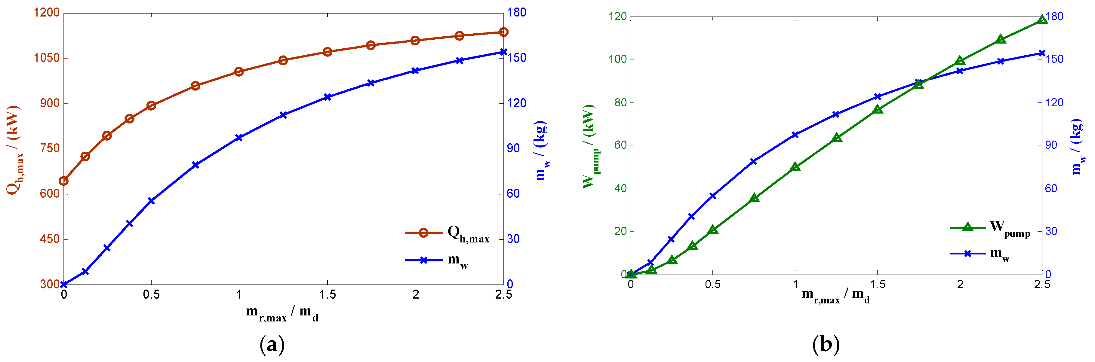
Figure 7.
Influence of Uwall on τthermal.
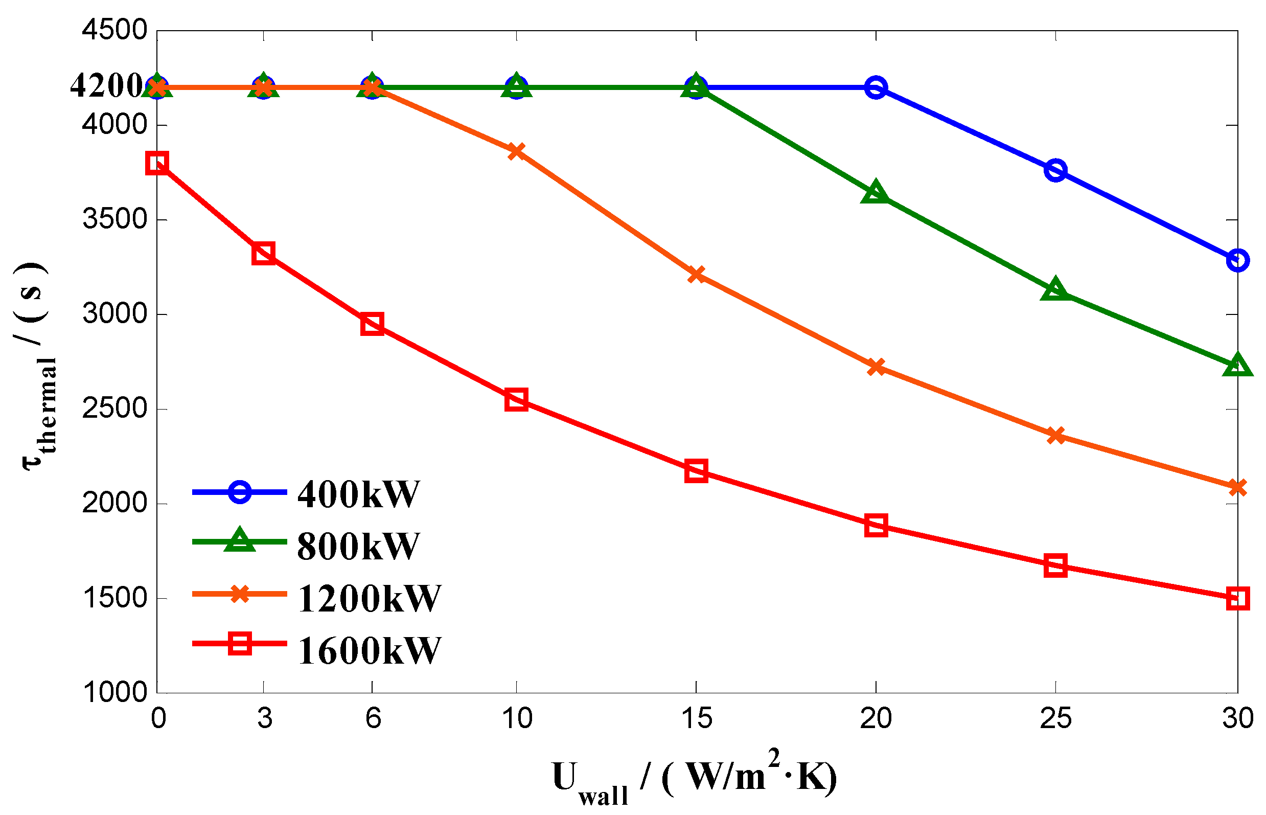
Figure 8.
Change trend of and .


Table 1.
Simulation conditions.
| Basical Parameters | |||
| Cruising Mach number | Ma | 4 | - |
| Flight altitude | H | 25 | km |
| Fuel tank remaining coefficient | εf | 40 | % |
| Thermal resistance of consumptive coolant-fuel Hex | 1/(UHExcAHExc) | 1/1500 | K/W |
| Fuel tank bottom area | A2 | 46.25 | m2 |
| Maximum area of tank side | A1 | 94.5 | m2 |
| Total heat transfer coefficient of wall | Uwall | 10 | W/(m2·K) |
| Initial fuel temperature | T0 | 293 | K |
| Fuel consumption rate | 4 | kg/s | |
| Maximum flow rate in circulation loop | 8 | kg/s | |
| Simulation time step | Δτ | 60 | s |
| Simulation Variables | |||
| Designed flight time | τthermal | (0, 70] | min |
| Initial carried fuel capacity | m0 | (0, 23520] | kg |
| Airborne thermal load | Qh | [400, 1600] | kW |
Table 2.
Simulation conditions.
| Basical Parameters | |||
| Cruising Mach number | Ma | 4 | |
| Flight altitude | H | 25 | km |
| Fuel tank remaining coefficient | εf | 40 | % |
| Thermal resistance of consumptive coolant-fuel Hex | 1/(UHExcAHExc) | 1/1500 | K/W |
| Fuel tank bottom area | A2 | 46.25 | m2 |
| Maximum area of tank side | A1 | 94.5 | m2 |
| Total heat transfer coefficient of wall | Uwall | 10 | W/(m2·K) |
| Initial fuel temperature | T0 | 293 | K |
| Fuel consumption rate | 4 | kg/s | |
| Simulation time step | Δτ | 1 | s |
| Designed flight time | τdesign | 4200 | s |
| Initial carried fuel capacity | m0 | 23,520 | kg |
| Simulation Variables | |||
| Airborne thermal load | Qh | [400, 1600] | kW |
| Maximum flow rate in circulation loop | [0, 16] | kg/s | |
Table 3.
Simulation conditions.
| Basical Parameters | |||
| Cruising Mach number | Ma | 4 | |
| Flight altitude | H | 25 | km |
| Fuel tank remaining coefficient | εf | 40 | % |
| Thermal resistance of consumptive coolant-fuel Hex | 1/(UHExcAHExc) | 1/1500 | K/W |
| Fuel tank bottom area | A2 | 46.25 | m2 |
| Maximum area of tank side | A1 | 94.5 | m2 |
| Initial fuel temperature | T0 | 293 | K |
| Fuel consumption rate | 4 | kg/s | |
| Simulation time step | Δτ | 1 | s |
| Designed flight time | τdesign | 4200 | s |
| Initial carried fuel capacity | m0 | 23,520 | kg |
| Maximum flow rate in circulation loop | 8 | kg/s | |
| Simulation Variables | |||
| Airborne thermal load | Qh | [400, 1600] | kW |
| Total heat transfer coefficient of wall | Uwall | [0, 30] | W/(m2·K) |
© 2018 by the authors. Licensee MDPI, Basel, Switzerland. This article is an open access article distributed under the terms and conditions of the Creative Commons Attribution (CC BY) license (http://creativecommons.org/licenses/by/4.0/).
Share and Cite
MDPI and ACS Style
Pang, L.; Li, S.; Liu, M.; A, R.; Li, A.; Meng, F. Influence of the Design Parameters of a Fuel Thermal Management System on Its Thermal Endurance. Energies 2018, 11, 1677. https://doi.org/10.3390/en11071677
AMA Style
Pang L, Li S, Liu M, A R, Li A, Meng F. Influence of the Design Parameters of a Fuel Thermal Management System on Its Thermal Endurance. Energies. 2018; 11(7):1677. https://doi.org/10.3390/en11071677
Chicago/Turabian StylePang, Liping, Shuxin Li, Meng Liu, Rong A, Aicheng Li, and Fanxin Meng. 2018. "Influence of the Design Parameters of a Fuel Thermal Management System on Its Thermal Endurance" Energies 11, no. 7: 1677. https://doi.org/10.3390/en11071677
Note that from the first issue of 2016, this journal uses article numbers instead of page numbers. See further details here.