Development of Honeycomb Methanation Catalyst and Its Application in Power to Gas Systems
by
 ,
,
Philipp Biegger
1, 
Florian Kirchbacher
2,
Ana Roza Medved
1,
Martin Miltner
2,
Markus Lehner
1,* and
Michael Harasek
2
1
Montanuniversitaet Leoben, Chair of Process Technology and Industrial Environmental Protection, Franz-Josef-Strasse 18, 8700 Leoben, Austria
2
Institute of Chemical, Environmental and Bioscience Engineering, Vienna University of Technology, Getreidemarkt 9/166, 1060 Vienna, Austria
*
Author to whom correspondence should be addressed.
Energies 2018, 11(7), 1679; https://doi.org/10.3390/en11071679
Submission received: 30 May 2018
/
Revised: 18 June 2018
/
Accepted: 20 June 2018
/
Published: 27 June 2018
(This article belongs to the Special Issue Power-to-Gas Energy Storage Technologies)
Abstract
:Fluctuating energy sources require enhanced energy storage demand, in order to ensure safe energy supply. Power to gas offers a promising pathway for energy storage in existing natural gas infrastructure, if valid regulations are met. To improve interaction between energy supply and storage, a flexible power to gas process is necessary. An innovative multibed methanation concept, based on ceramic honeycomb catalysts combined with polyimide membrane gas upgrading, is presented in this study. Cordierite monoliths are coated with -Al2O3 and catalytically active nickel, and used in a two-stage methanation process at different operation conditions (p = 6–14 bar, GHSV = 3000–6000 h−1). To fulfill the requirements of the Austrian natural gas network, the product gas must achieve a CH4 content of ≥96 vol %. Hence, CH4 rich gas from methanation is fed to the subsequent gas upgrading unit, to separate remaining H2 and CO2. In the present study, two different membrane modules were investigated. The results of methanation and gas separation clearly indicate the high potential of the presented process. At preferred operation conditions, target concentration of 96 vol % CH4 can be achieved.
1. Introduction
The global efforts to reduce greenhouse gas emissions and decarbonization of power supply cause major changes in all sectors of the energy economy. Since renewables are highly fluctuating, an increasing energy storage demand is predicted [1,2], which is necessary to ensure a secure supply. Generally, a shift from a fossil fuel based economy to an electric energy dominated system is expected. Nevertheless, fuel based networks like the natural gas grid offer enormous storage potential and are also capable of transporting huge amounts of energy. A link between electric and chemical energy could be a promising option to fulfill the requirements of the energy transition.
Power to gas technology can be used to convert electric power to chemical energy for storage. The core technique therein is water electrolysis, responsible for the energy conversion by using electrical power to split water into H2 and O2. In a medium- to long-term perspective, H2 could play a key role in energy supply as it provides beneficial characteristics: first of all, hydrogen is a carbon free fuel and can be used in stationary and mobile applications. Secondly, it can be stored in pressure tanks or underground gas storages in large-scale amounts. Generally, gas networks provide considerably more storage capacity compared to electric power grids. Lastly, the public acceptance for a clean fuel is expected to be quite high, which is also an essential property for future applications. On the downside, current energy infrastructure (electricity, mineral oil, natural gas) and customer structure (low demand, small number of customers) is not ready for a hydrogen economy.
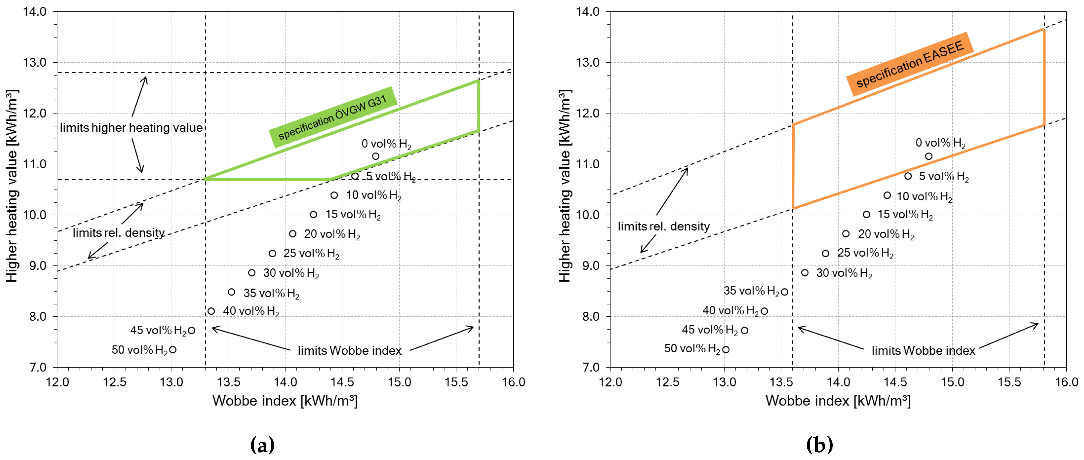
Unlike H2, natural gas is widely available with already fully developed infrastructure for transport, storage and utilization. Since H2 and natural gas are gaseous fuels, a blend of those two gases is conceivable. Even higher H2 contents are technically possible, as already demonstrated in town gas applications [3]. A mixture of natural gas and H2 could be the solution for the mentioned structural problems. Although natural gas qualities are regulated on national and international levels, the admixture of small amounts of H2 (≈5 vol %) to the natural gas is tolerated in central Europe. According to the Austrian regulations [4], up to 4 mol % of H2 is allowed, which is compliant with other key figures like heating value, relative gas density and Wobbe index. Higher H2 contents have a significant impact on these key figures and the gas blend would be out of specification. Figure 1 shows the effects of H2 on typical gas key figures, based on natural gas type Russia H (initial composition in Table 1).
To circumvent the present structural problems of H2, an additional process step, methanation, can be used, where H2 is combined with CO and/or CO2 to form CH4 and H2O. The underlying Sabatier reactions are given in Equations (1) and (2):
The methanation of CO (Equation (1)) and CO2 (Equation (2)) are linked via the reverse water–gas shift reaction in Equation (3):
The Sabatier process and the water–gas shift reaction are catalyzed by metals of IUPAC (International Union of Pure and Applied Chemistry) groups 8 to 10. Usually, nickel based catalysts are the preferred choice due to their high catalytic activity, high CH4 selectivity and comparably low costs [7]. Regarding process design, three basic concepts were developed:
- fixed bed methanation (bulk and honeycomb catalysts),
- fluidized bed methanation, and
- three phase methanation.
On a commercial scale, fixed bed processes are dominating [8,9] and are offered by different companies [10]. Besides power to gas applications, fixed bed methanation is a state-of-the-art technology for gas cleaning units e.g., in ammonia plants [9]. As seen in Equations (1) and (2), the reactions are highly exothermic, thus appropriate heat management of the reactors is very important. Various reactor concepts including product gas recycle as well as internal and external heat exchangers were developed [9,10].
The present study deals with the combination of catalytic methanation and membrane based gas upgrading in a proof of concept. Each process unit includes innovative approaches to fit the requirements of a fluctuating energy storage application. While methanation is using a ceramic honeycomb as a substrate for the nickel catalyst, gas upgrading is done with tailored polyimide membranes for high methane selectivities. On the one hand, the used setup should demonstrate the function of honeycomb methanation catalysts and the membrane gas upgrading by fulfillment of local natural gas quality regulations. On the other hand, impact of operation parameters like pressure level and space velocity on process control and product gas composition are determined.
High methane concentrations in the product gas are achieved by catalytic methanation only under stable process conditions. If methanation is going to be used for power to gas systems on a large scale, product quality needs to be ensured for changing process conditions, making additional gas upgrading necessary.
Besides steam, which is easily condensable, the main impurities remaining after methanation are H2 and CO2. For CO2 removal from CH4, various options are commercially available for biogas upgrading. Most commonly used are (according to [11]):
- water scrubbing (market share approx. 40%),
- physical absorption (market share approx. 6%),
- chemical absorption (market share approx. 25%),
- pressure swing adsorption (market share approx. 25%), and
- membranes (market share approx. 4%)
Water scrubbing is based on the comparatively low solubility of CH4 in water. It uses relatively large reactor volumes and needs high quantities of water, even if water is recycled. The process is normally operated in a range of 6–10 bar [12]. One advantage of the process is that it can deal with H2S impurities, as H2S is absorbed into water [12]. Regeneration is done in a second column by contacting with air. Negative is the potential introduction of N2 and O2 into the process chain during the desorption step [13]. To reduce costs, treated water can be used for the process instead of fresh water, but it aids microbial growth [12].
A similar option is physical absorption in polyethylene glycol and its derivates. They offer higher solubility for CO2 and need therefore smaller vessels than water scrubbing [14]. Regeneration is performed at elevated temperatures of 55–80 °C [13]. Opinions on whether H2S removal is necessary differ [12,14] but is generally done prior to physical absorption [12].
Chemical absorption offers a highly selective option for CO2 removal. In this case, alcanol amines like methyldiethanol amine (MDEA) are used as absorbents. While high selectivity leads to reduced CH4 losses, regeneration needs to be done at temperatures of 120–150 °C [13]. This decreases the process competitiveness compared to the alternatives, as parts of the product CH4 must be used for heat generation [15]. Other disadvantages are the need of desulfurization [12] and increased corrosion and chemical consumption, due to oxidative degeneration of amine solution [13].
Pressure swing adsorption is based on a combination of molecular size exclusion and adsorption affinity [12]. Commonly used adsorbents are zeolites, silica gels and carbon molecular sieves [13]. Set-up of the process is complex, demanding at least four columns operated in parallel for pressurization, adsorption at 6–10 bar, depressurization and desorption at ambient pressure [12]. However, advantageous are low power demand as well as low emissions [16]. Except for the necessity of prior H2S removal [14], no additional costs for water make-up or heat for regeneration occur [12].
The last option of commercially available upgrading techniques is membrane gas separation, based on differing permeability for components through membrane materials. Most common materials used for natural gas cleaning include polyimides and cellulose acetate membranes, as they offer good selectivity for CO2/CH4 [17]. Operating pressure is in the range of 5–30 bar to ensure sufficient CH4 enrichment. While membrane based gas upgrading offers low cost, high energy efficency, easy process as well as excellent reliability [16], it has been criticized for lower CH4 recoveries compared to the other options. This trade-off between product purity and recovery can be circumvented by a multistage layout [17]. An improvement of CH4 recovery from 80% for a one-stage process to 99.5% has been reported [13] but also leads to a higher specific energy demand [18].
Regarding achievable product purity, all processes are able to achieve concentrations higher than 96 vol % CH4 with CH4 losses of less than 2% [12] and are able to meet common gas grid standards. Costs are reported to be ranging from 0.15 €/m3 to 0.25 €/m3 depending on plant size, with costs favoring membranes and chemical absorption for smaller plants up to 1000 m3 and water scrubbing for larger capacities [13]. This is also supported by the number of realized plants [11].
Innovation
Originally, methanation processes were developed for syngas applications to produce SNG (Synthetic Natual Gas) from coal [9]. These plants are designed for long-term steady state operation with defined feed gas compositions. The requirements for a power to gas process differ quite considerably. Due to the fluctuating supply of H2, gas storage is often necessary, which can be avoided by load flexible operation as well as good start up and stand by behavior. Besides large scale plants, also smaller, decentralized power to gas units are possible. Depending on the carbon source, impurities like sulfur compounds must be expected. Therefore, tailored gas cleaning devices are also part of the system.
To improve load flexibility, stand-by and response characteristics, a new methanation concept based on washcoated honeycomb catalysts was developed. Monolithic honeycombs consist of ceramic or metallic blocks with channels of different shapes (square, triangular, hexagonal). They have been in use for decades and standard in automotive applications [19]. Often honeycombs are just a carrier structure for the catalytic material, which has to be applied via coating. Structured catalysts offer several advantages like low pressure drop, simplified scalability, homogeneous flow and low axial mixing [20,21]. Adverse effects are limited heat transport, hindered temperature control, smaller geometric surface compared to bulk catalysts and costly production [20,21].
Ceramic monoliths are used in heat recovery applications, due to their low thermal expansion, thermal conduction and high thermal shock resistance. These properties can also be advantageous in a methanation process. For nickel catalysts, it is necessary to achieve a minimum reaction temperature of 200 °C to avoid the formation of toxic [Ni(CO)4]. To reduce trace heating during stand-by, the heat of reaction can be stored by the honeycombs. Furthermore, a multi bed reactor concept with additional chambers in each stage should support heat storage and operation flexibility.
Multi bed reactors are commonly used in applications where thermodynamics or reaction kinetics require temperature restrictions. Therefore, the reactor is divided in two or more stages, which can be cooled directly or indirectly. Furthermore, gas recycles and fresh gas injections are possible. A well-known application of multi bed reactors is the Haber–Bosch process [22]. Compared to a series of single reactors, heat losses are lower, although much more complex.
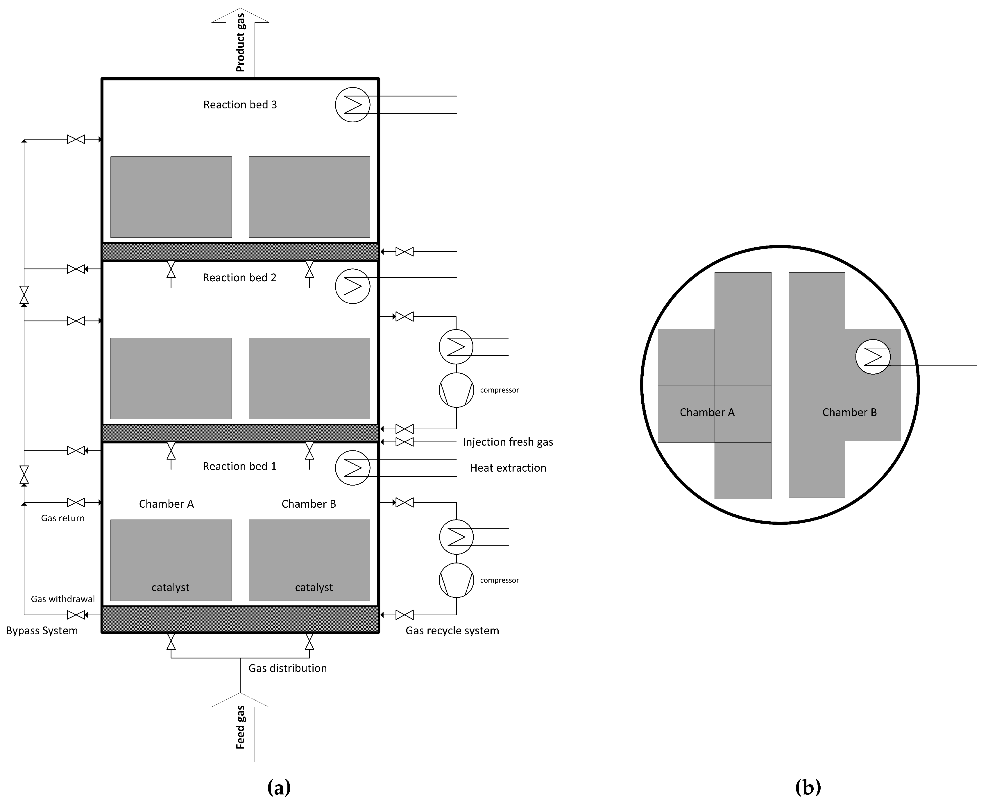
The proposed multi bed reactor process is designed with three beds and up to four chambers per stage. While the beds support a controlled heat build-up, the chambers are responsible for high load flexibility. At 100% load, all chambers are equally used, and each catalyst bed is operated at its design point. By locking individual chambers, the operating window is lowered, e.g., 50% load for 50% used chambers. Additionally, the catalysts themselves have an operating range. Consequently, very low capacities can be reached (one of four chambers with a catalyst operating at 50% results in 12.5% total load). For quick response of the reactor system, all chambers and beds must be kept on stand-by temperatures above 200 °C. Besides catalytic function, honeycomb is used as heat storage inside the vessel, since heat of reaction is stored in ceramic monoliths. This can also be achieved during operation at low capacities, by cyclical switching between chambers. A schematic illustration of the reactor concept can be seen in Figure 2.
This load flexibility in the methanation step demands an equally flexible gas upgrading system. The gas upgrading needs to have a fast response rate, being able to handle a large bandwidth of flow rates and also deal with varying gas compositions. Membrane systems in general are highly flexible regarding changing flow rates by adapting the available membrane area due to their modular design [24] and have virtually no response time. Changing composition of the main compounds H2, CO2, CH4 and H2O due to varying conditions in the methanation can be addressed by the use of polyimide hollow fiber membranes. Polyimide offers a high selectivity for both H2/CH4 and CO2/CH4 [25] as well as H2O/CH4. This is one of the main advantages compared to the other gas upgrading systems presented as it allows simultaneous removal of CO2 and H2, whereas water scrubbing, chemical absorption and adsorption can only remove CO2. Negative is the potentially large loss of CH4 to the off-gas. To circumvent this problem, the off-gas could be compressed and directly recycled to the methanation, while improving the overall conversion of CO2 and H2 by negating any losses of CO2 and H2 [17]. This is possible because the process is purely physical and neither H2 nor CH4 are chemically transformed. Furthermore, the process setup itself, consisting mainly of a compressor and membrane modules, is rather simple compared to a cyclical process like adsorption leading to relatively low costs. For the injection into the natural gas grid, it is also beneficial that the product stream is already at an elevated pressure level reducing compressor cost to meet injection pressure. A combination of catalytic methanation using a honeycomb structured catalyst and membrane based gas upgrading has yet not been demonstrated, but offers a very promising concept for a highly load flexible power to gas pathway.
2. Results
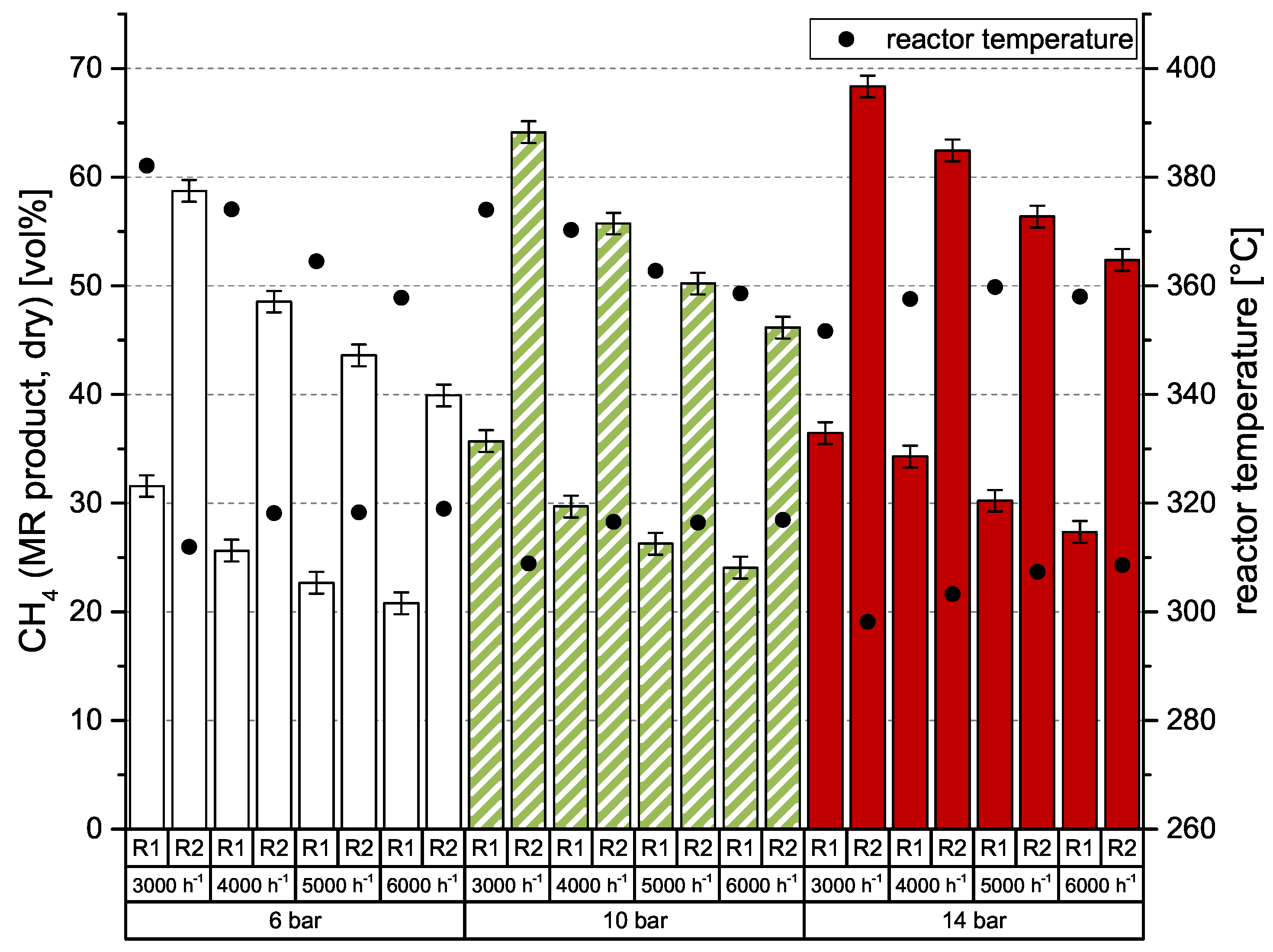
As known from previous investigations of catalytic methanation [26,27,28], there is a strong dependency of CO2 conversion on GHSV (gas hourly space velocity) and pressure level. For best results, high pressures and low space velocities are preferred. Of course, the number of reaction stages is also important. This behavior was also observed in the current experiments, which were conducted with an undiluted, stoichiometric mixture of H2:CO2 = 4.0. Results are shown in Figure 3. The left y-axis represents the dry CH4 content after a particular methanation reactor (MR). Additionally, the right y-axis shows the reactor temperature, which was measured directly below (gas entrance) the honeycomb catalyst. At 6 bar, the catalytic methanation achieves comparably poor results, but with a low space velocity of 3000 h−1 even 58.7 vol % CH4 is possible. It also can be seen that the CH4 content is nearly doubled in the second reactor stage. According to earlier experiments [26,27,28], conversion rates are decreasing with increasing space velocity. To improve conversion rate and consequently CH4 level of the product gas, the system pressure needs to be adjusted to higher values. The impact of 10 and 14 bar compared to 6 bar is also depicted in Figure 3. While 10 bar leads to an increase of approx. 5 vol % CH4, a system pressure of 14 bar allows for an improvement of ≥10 vol % CH4 after reactor 2 (R2). Due to the arrangement of the temperature sensors and the high heat losses of the vessel, the reactor temperature remains quite constant between 350 and 380 °C for R1 and 300–320 °C for R2.
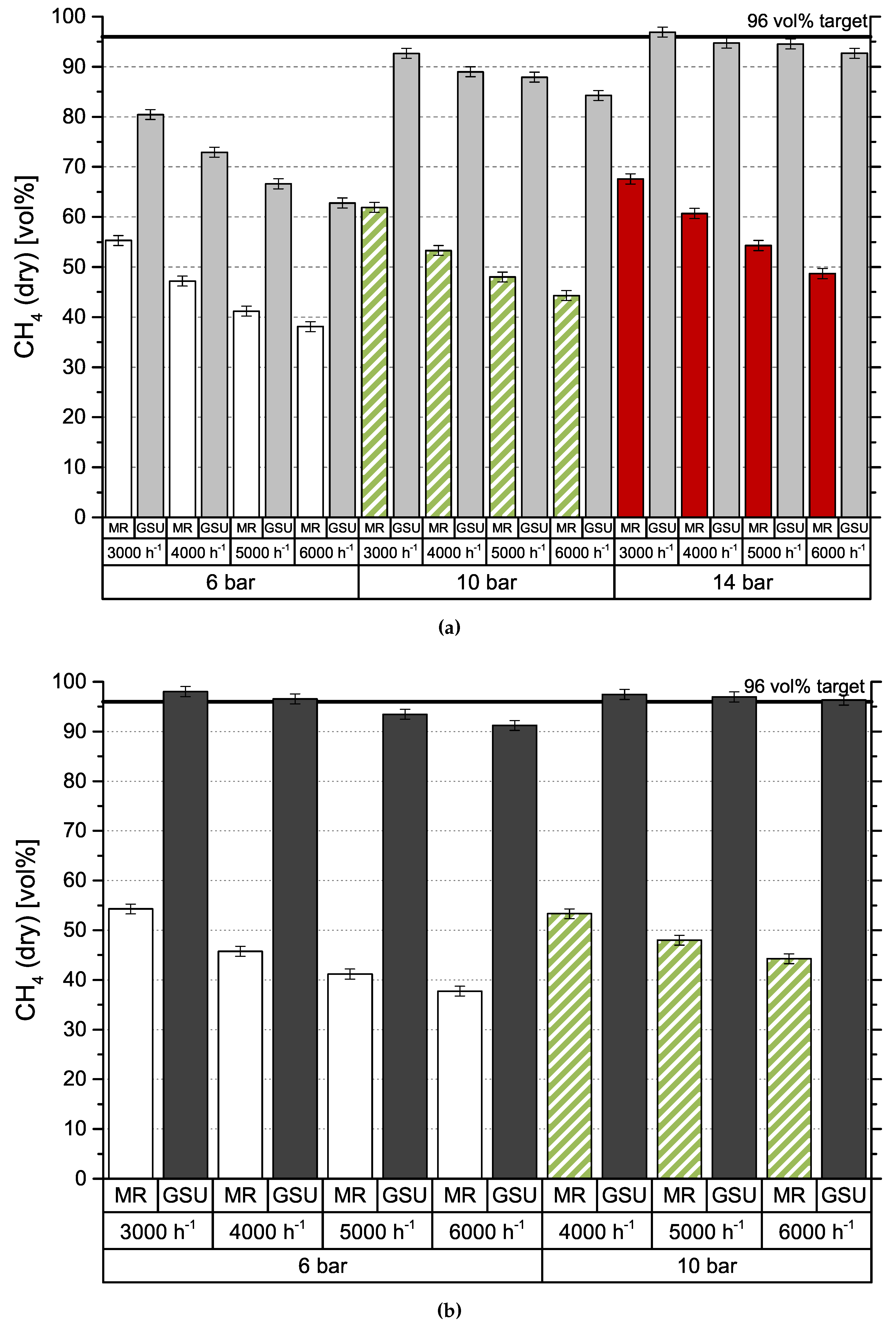
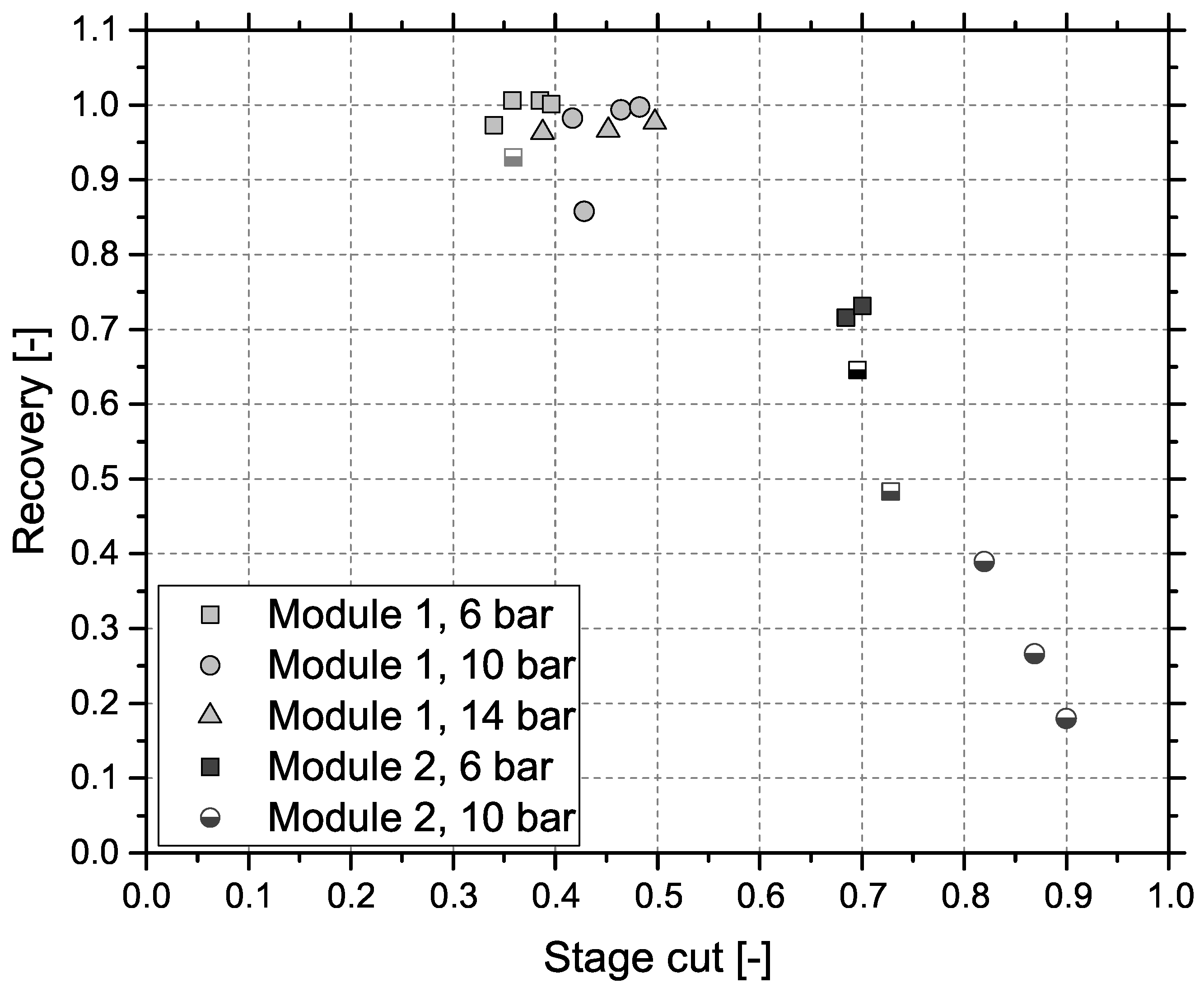
Figure 4 shows the results obtained by gas separation unit (GSU) in the combined process. The presented feed composition (MR) differs from results in Figure 3 (R2), which is caused by the experimental setup. Since both test plants are originally designed for stand-alone operation, they use separate gas analyzers. Furthermore, data cannot be collected simultaneously, due to the impact of gas sampling on downstream processes. Consequently, values are measured at different dates, process conditions deviate slightly and CH4 content is varying. Results for module 1 can be seen in Figure 4a. Most importantly, the targeted product gas quality of 96 vol % CH4—to comply with Austrian natural gas regulations—can be accomplished, but only for the lowest GHSV of 3000 h−1 and the highest pressure level of 14 bar. At 6 bar, CH4 concentration increases by around 25 vol % independent of GHSV. Elevated pressure levels show an improved increase in CH4 concentration from 30 vol % (GHSV = 3000 h−1) to 40 vol % (GHSV = 3000 h−1) at 10 bar and from 30 vol % (GHSV = 3000 h−1) to 45 vol % (GHSV = 3000 h−1) at 14 bar. Module 2, with results depicted in Figure 4b, shows a very different picture. For the same set of inlet concentrations from methanation, the targeted product specification is achieved at 6 bar at GHSVs 3000 h−1 and 4000 h−1 and for all experiments conducted at 10 bar. An experimental assesment of module 2 at 14 bar was not possible, due to the module’s high permeances compared to module 1. Figure 5 represents CH4 recovery (see Equation (4)) on the y-axis versus stage cut (see Equation (5)) on the x-axis. The semi-filled markers indicate experiments that fulfilled the target CH4 concentration:
All experiments for module 1 showed an extremely high CH4 recovery of at least 0.85 and therefore little CH4 losses to the off-gas with comparatively low stage cuts ranging from 0.3 to 0.5 indicating a low off-gas flow rate. While module 2 showed more promising results regarding product gas CH4 concentration, recovery is low dropping down as far as 0.19 with high stage cuts between 0.7 and 0.9.
3. Discussion
The honeycomb catalyst is in its early development stage, thus its full potential has not been used yet. Besides geometrical parameters like length, channel number and channel width, the coating process also needs further improvements. Basically, the honeycomb catalyst works stable, reliable and behaves like a commercial bulk catalyst. Compared with bulk catalyst Meth 134®, the commercial product shows higher catalytic activity, which consequently causes increased conversion rate and reactor temperature [29]. Nonetheless, the methanation results are promising and prospects for further development is good.
Basically, test plants often have to deal with issues caused by their size, since surface:volume ratios of vessels and pipes are much higher than in pilot scale, which is also occurring in the present case. Due to reactor design specifications (750 °C, 21 bar), vessels of the utilized test plant are very heavy with a single weight of 190 kg. Besides its poor handling, heat losses are high. Despite insulation and exothermic methanation reaction, vessels need to be heated during experiments. Furthermore, the structure of honeycomb catalysts does not allow temperature measurement inside channels, resulting in lower registered temperatures than expected peak reaction temperatures. These properties and placing of thermocouples are causing distorted temperature measurement and management. To overcome the aforementioned issues, new custom pressure vessels with drastically reduced weight (12.5 kg at comparable volume) were installed. First experiments prove the estimated improvement, since reactor temperatures are higher and heat losses are lower. Consequently, conversion rates are decreasing.
Results presented for the combined approach of methanation and membrane based upgrading proved to be very promising and the effects of different membrane modules are clearly apparent. Module 1 is able to achieve the necessary product gas quality only under the most favorable conditions, low GHSV combined with high pressure. Data (see Figure 4a) obtained at 6 bar show a constant improvement of 25 vol % CH4 due to the upgrading step. Results at 14 bar show a drop of 4 vol % CH4 due to GHSV after the GSU while the methanation step dropped considerably from 68 vol % CH4 to 49 vol % CH4. This indicates that the role of GHSV is secondary compared to the pressure for the gas upgrading step. Data from module 2 (see Figure 4b) show some important differences. Although selectivities are lower, product quality can be achieved at lower pressure levels and/or higher GHSVs due to the higher module permeances. The trade-off is a much higher stage cut—at least 0.7 instead of approx. 0.4—and reduced recovery—0.65 compared to approx. 0.95. Furthermore, it was not possible to operate module 2 at GHSV = 3000 h−1 and 10 bar as well as at 14 bar in general. The reason for this is that the stage cut for this operating conditions approached 1 and the necessary pressure could not be kept constant.
This leads to the following conclusions for the use in a power to gas concept. A load flexible honeycomb catalyst can be used in combination with a single-stage membrane GSU to produce SNG in compliance with common gas grid standards. A highly selective membrane module with a well designed membrane area would be able to achieve this at higher pressure levels and low GHSVs with a CH4 recovery above 90% but would fail outside this narrow operation window. Furthermore, stage cut would still be around 0.35, meaning that 35% of the total volume flow consisting mainly of CO2 and H2 would be lost to the off-gas. Installing additional membrane modules in parallel would allow for adapting this system to the process’s needs, but would also increase the capital costs. Using a membrane that offers higher transmembrane fluxes but has a lower selectivity means that less modules are needed for operation in comparable conditions and it appears to be more flexible regarding pressure and GHSV. However, this would also increase off-gas flowrate, decrease recovery and therefore lower overall efficiency. To prevent this, a recycle of the off-gas to the methanation reactor has to be included in this scenario. Implementation of a two-stage membrane setup is an additional opportunity for improvement, since it would enhance recovery rate and balance fluctuations in catalytic methanation.
4. Materials and Methods
4.1. Ceramic Honeycomb Catalyst
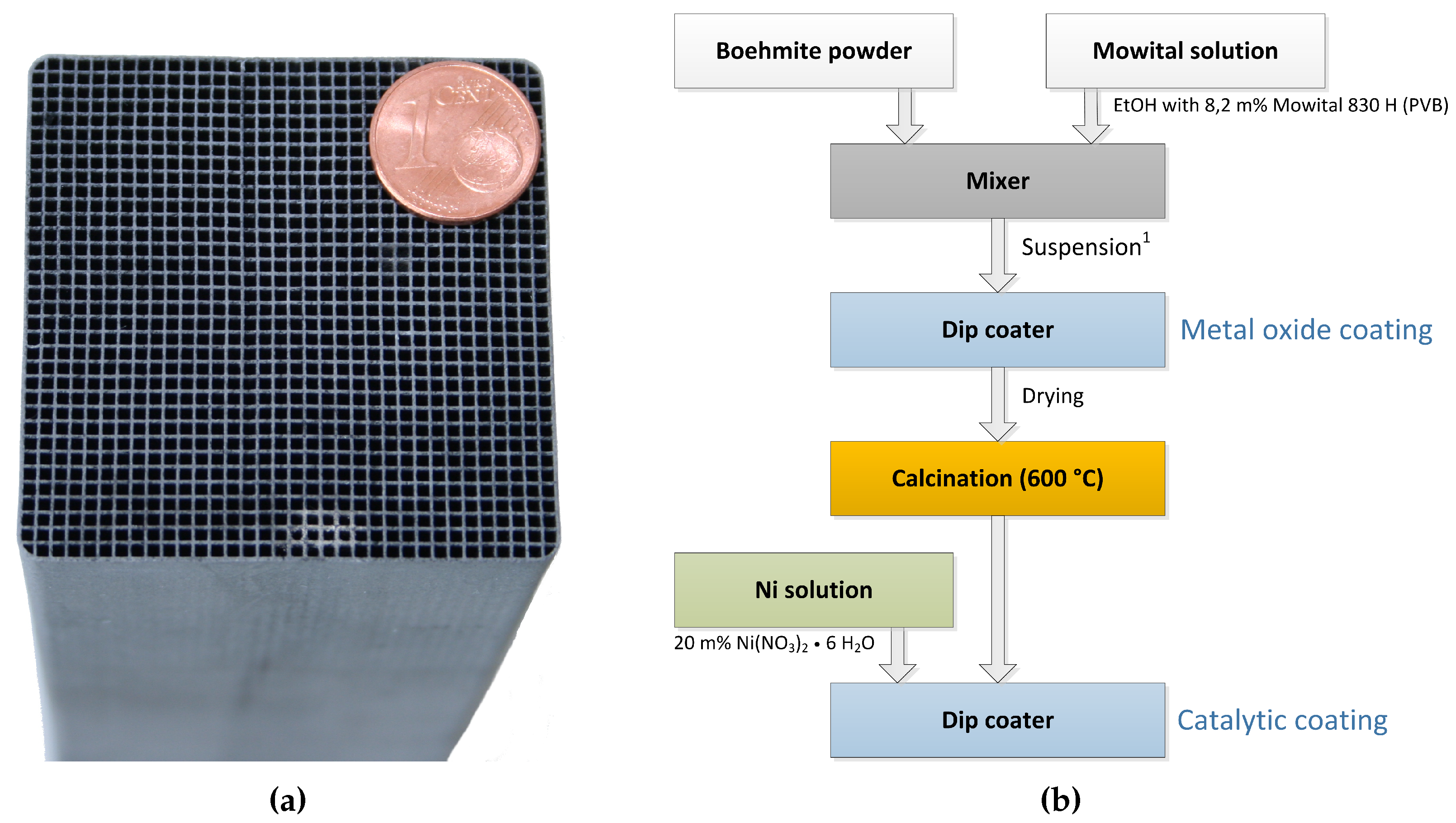
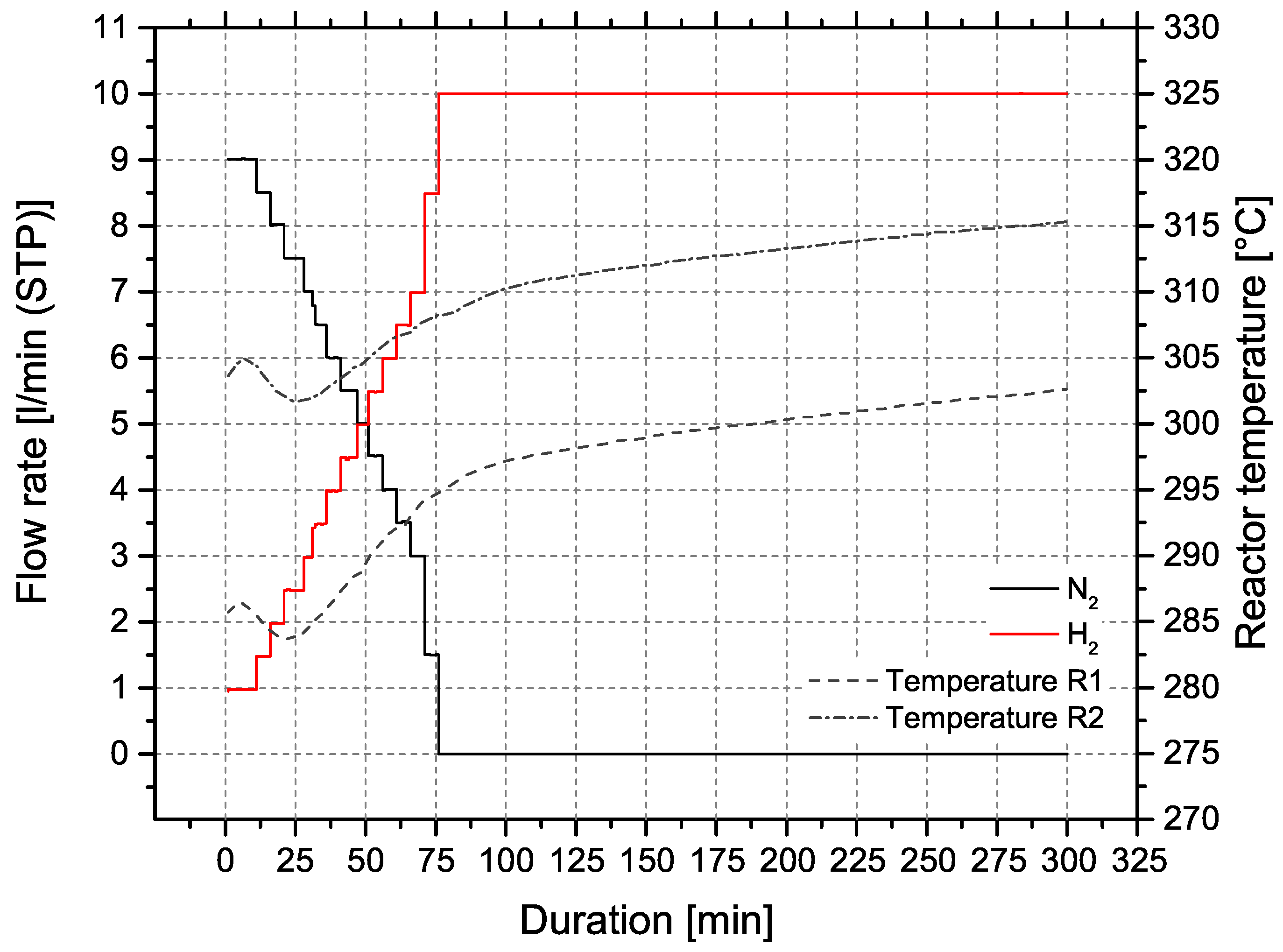
The ceramic honeycomb catalyts consist of cordierite Mg2Al3[AlSi5O18]. Compared to other substrate materials, ceramic honeycombs offer large pores and low specific surface areas of approx. 0.3 m2/g. To provide the needed surface area of >100 m2/g the carrier material is coated with inorganic oxides like -Al2O3 or 3% Y2O3-stabilized ZrO2 (t-ZrO2). In a subsequent dip coating step, the catalytic active material Ni is applied. Figure 6b illustrates the coating process for nickel/-Al2O3 catalysts on cordierite support (Figure 6a), developed by Fuchsbauer et al. [30]. In a first step, 38.4 g boehmite powder -AlO(OH) and 60.0 g binding agent (8.2 m% Mowital 830 H in ethanol) are mixed, followed by dip coating of the ceramic honeycomb. After drying and calcination at 600 °C, the catalytically active layer is applied by dip coating 20 m% Ni(NO3)2·6H2O. Finally, the coated monolith is dried to constant mass and is ready for activation in the reactor. The catalyst activation was conducted with a defined N2:H2 ratio and a temperature of 300 ± 15 °C. Figure 7 shows the activation process of both reactors at ambient pressure.
For the current experiments, a honeycomb with square channels was used (Figure 6a). Its dimensions were A × B × H = 50 mm × 50 mm × 142 mm with a cell density of 300 cpsi (channels per square inch). More details about catalyst geometry and coating can be found in Table 2. The two catalysts were applied during all experimental runs.
A common value to compare catalyst load is gas hourly space velocity, GHSV. It is calculated by the quotient of volumetric flow rate (STP) and catalyst volume (Equation (6)). The higher the space velocity, the higher the catalyst stress. Since the flow rate is considered at standard conditions, the influence of system pressure is not described by GHSV. During the experiments, space velocities in the range of 3000 h−1 to 6000 h−1 were used:
4.2. Lab Scaled Methanation Test Plant
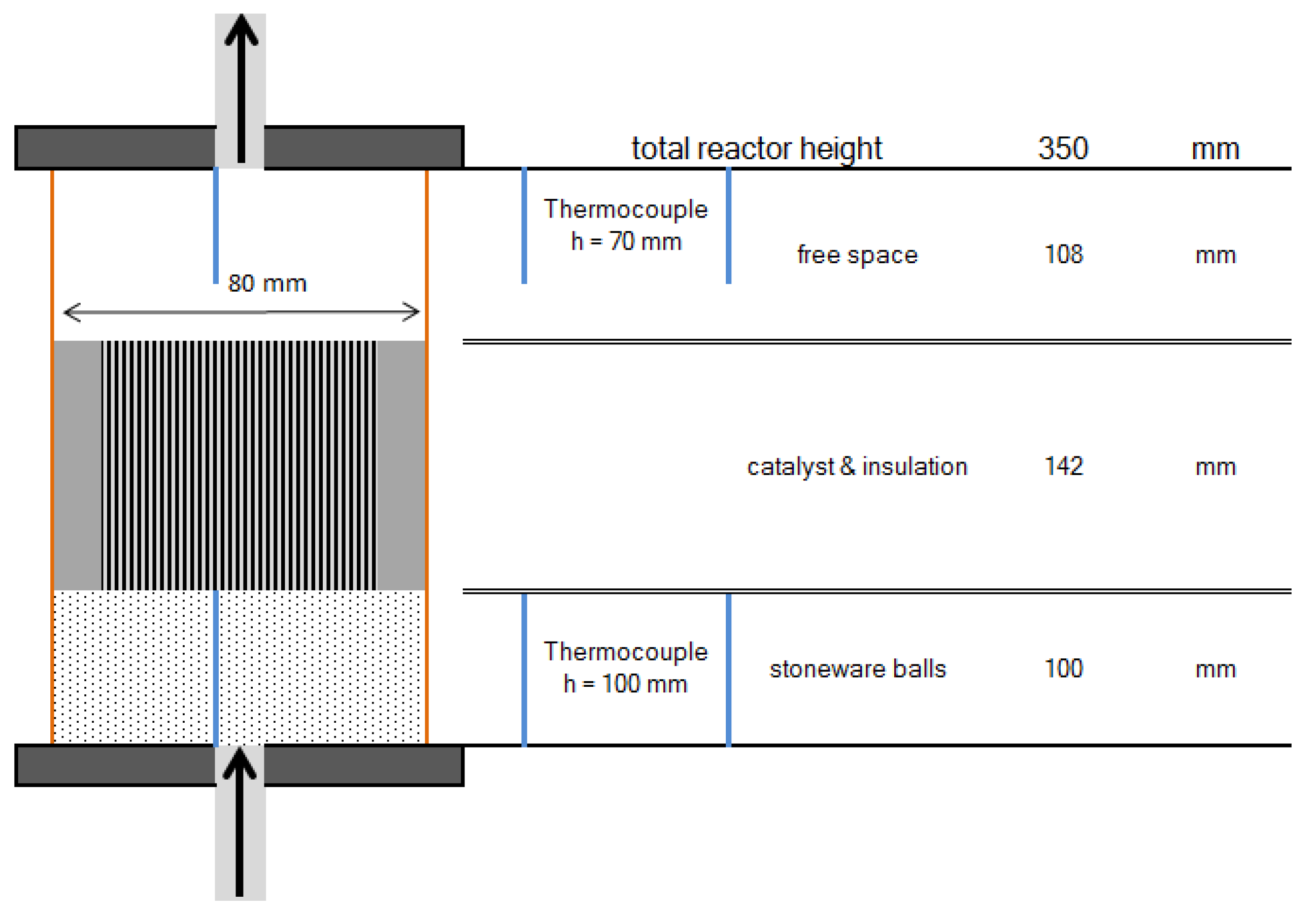
To investigate the behavior of the structured catalysts, a lab scaled test plant was used. Contrary to the planned multi bed reactor (see Figure 2), it consists of separate reactors. Due to the complexity of staged reactor systems, an implementation on a lab scale was dismissed. Similar to the proposed methanation process, the test plant includes up to three reactors, which can be operated separately or in series. Each reactor is filled with 100 mm of HiDur™ stoneware balls (RVTPE, Steinwiesen, Germany) 3/8”, in order to ensure an even flow through the catalyst, which is placed on top of the packed bed. Clearance between catalyst and reactor wall is filled with compacted insulation material (mineral wool). Furthermore, two type K thermocouples are installed inside the reactor to measure temperature directly below and above the honeycomb catalyst. A schematic illustration of reactor setup is depicted in Figure 8.
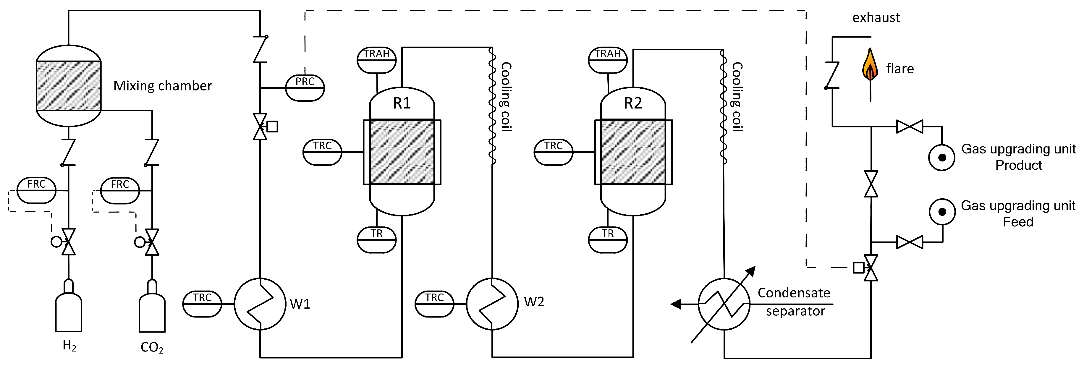
For the present experiments, only two reactors were used. The process is designed for pressures up to 20 bar and maximum feed gas flow rates of 3 m3/h (STP). A simplified flow chart is shown in Figure 9. Reaction gases H2 (Hydrogen 5.0, purity 99.999%, Linde Gas, Stadl-Paura, Austria) and CO2 (BIOGON® C, E290, purity 99.7%, Linde Gas, Stadl-Paura, Austria) are charged from gas bottles via mass flow controllers and blended in a mixing chamber. Contrary to real plants, separation of trace components like H2S or dust was not necessary. Next, the reaction gas is pre-heated in heat exchanger W1 to >200 °C and fed into the first reactor R1. To ensure a minimum reaction temperature of 250 °C, all reactors are equipped with electric trace heating systems. During operation, reactor temperatures are increasing due to the exothermicity of the reaction. Subsequently, the outlet gas of R1 is air cooled in a cooling coil to avoid temperature induced damage of valves and other equipment. The following reactor stage is similar to the first conversion step and consists of pre-heater W2, reactor R2 and a cooling coil. Finally, the produced gas is cooled and condensate is separated. A total number of four gas sampling points allows analysis of input and output gas composition of the particular reactor (infrared photometer URAS26 by ABB: CO, CO2, CH4; thermal conductivity analyzer CALDOS27 by ABB: H2, Vienna, Austria; calibrated). For the combination of methanation plant and gas upgrading unit a connection point is included. Since the gas is flammable, it has to be combusted in a lab flare before feeding it into the exhaust gas system.
4.3. Membrane Gas Upgrading
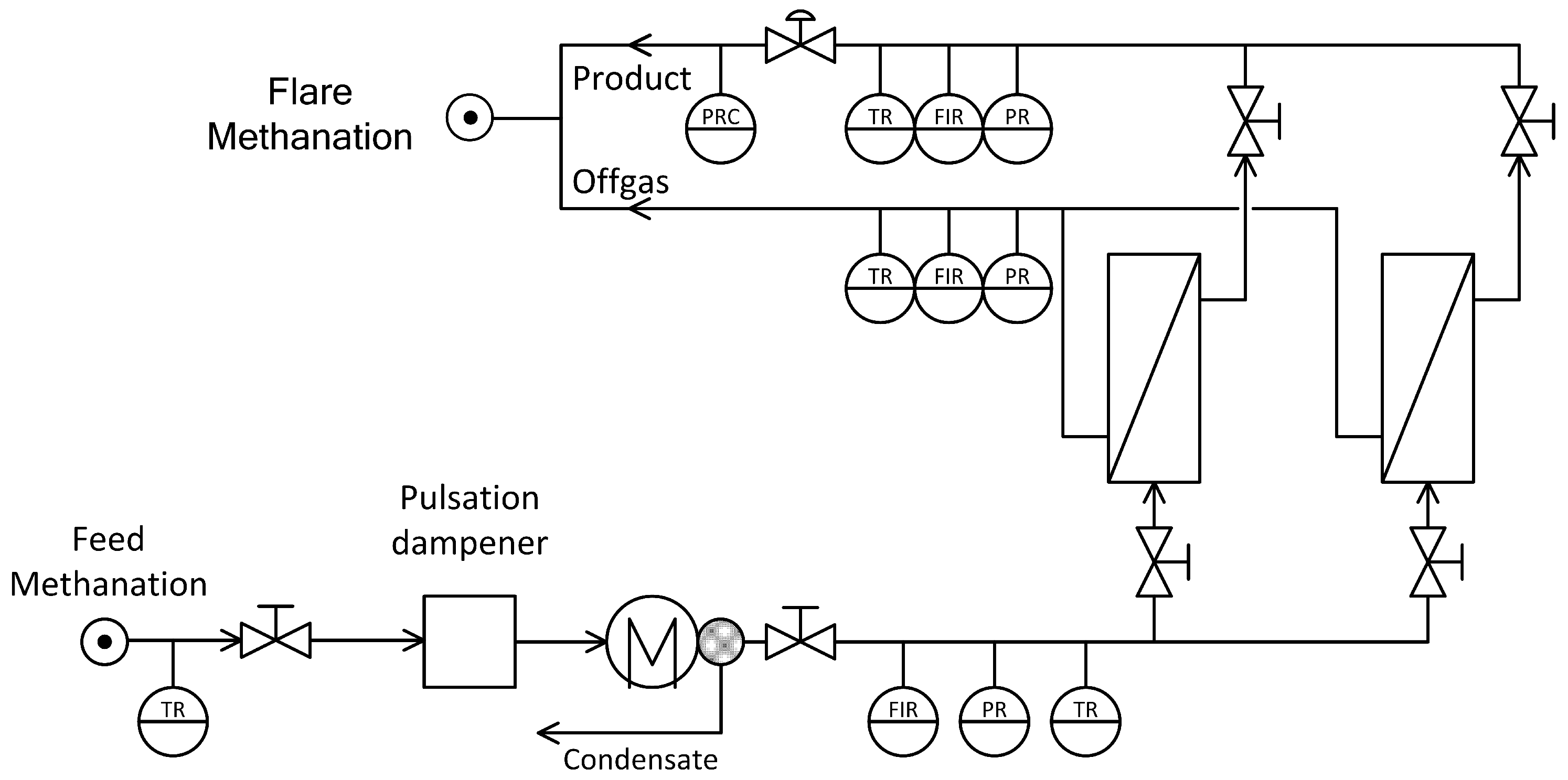
To assess the influence of the membrane based gas separation unit on the process, a lab-scaled demo plant was realized. The simplified flow sheet is depicted in Figure 10. The setup consists of a pulsation dampener, condenser, membrane unit and gas analysis. Gas from methanation enters and is fed into the pulsation dampener to prevent any damage to membranes or analytic equipment in case of unforeseen pressure changes. It is then dried at 4 °C to prevent condensation on the membrane surface. Two different polyimide membranes have been used to see the effects of module size and selectivity on product gas quality, CH4 recovery and stage cut. While both modules are polyimide based with similar outer dimensions, they vary in both permeance and selectivity. Ideal selectivities and relative pure gas permeances P for both modules are given in Table 3. The selectivity of was not determined for the applied modules, but literature indicates values in the range of 2.0 to 4.5 [31]. Hence, an efficient separation of CO and CH4 with polyimide membranes is not possible.
The setup allows for separate use of each module or parallel use if an increased membrane area is needed, while only the former has been applied in current study. For each stream-feed from methanation, final product gas and off-gas-pressure, temperature, flow rate as well as concentration of CH4, CO2, H2 and CO are measured. Detection of the gaseous compounds (Gas Analyser GMS810 by SICK, Wiener Neudorf, Austria; calibrated) is done via infrared spectroscopy (Type: MULTOR) and heat conductivity (Type: THERMOR). All gas streams were then recombined and combusted. Operation for the membrane part is limited by pressure (16 bar) and process flow rates of up to 6 m3/h (STP).
4.4. Combined Process
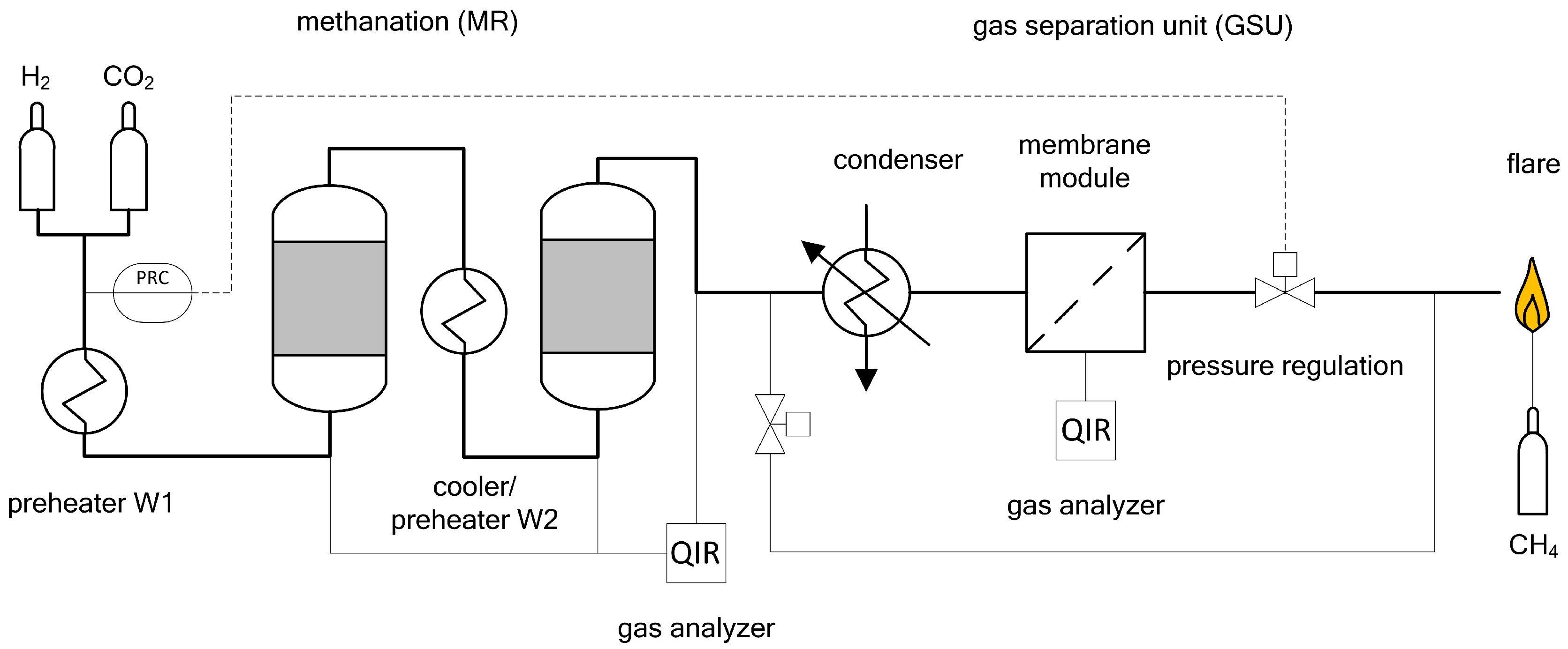
For the conducted experiments, both test plants were combined in series, and methanation followed by gas upgrading (Figure 11). To ensure comparable system pressures, a proportional valve at the end of the process was used to adjust and control pressure. Consequently, methanation and gas upgrading were operated at the same pressure level, as long as pressure losses are neglected. To avoid mixing effects during gas sampling, each process setting was kept between 60 (6 bar) and 120 min (14 bar). A similar setup was presented by the authors in [29], using commercial catalyst for methanation. The presented results are single run experiments, though half of the experiments were repeated to verify reproducibility. Due to the experimental setup, it is not possible to obtain consistent process conditions, since reactor temperature is influenced by duration of experiment, system pressure and catalytic activity. If measurements are repeated within short time periods during the actual experiments, the results are within measurement certainty. Hence, the monitored reproducibility is satisfying.
5. Conclusions
The presented concept, consisting of a methanation step, using newly developed honeycomb catalysts, and polyimide membrane gas upgrading, shows promising results for power to gas applications. Despite the early development stage of catalysts and lab scaled test plants a high quality SNG, in compliance with common natural gas network standards, can be produced. With further development of catalysts and optimized methanation operating conditions the conversion rate could be increased. Consequently, the decreased amount of H2 and CO2 is leading to an improved performance of the gas upgrading section. Regardless of methanation efficiency, membrane modules must be tailored to a fixed operating point or designed to handle varying conditions, either by parallelization or inclusion of a recycle loop, as results indicate high dependence between operating window and product gas quality.
6. Patents
Friedacher, A.; Biegger, P. Patenteinreichung: Anlage zur katalytischen Methanisierung, Aktenzeichen: A51029/2015, 01.12.2015. (translated: Friedacher, A.; Biegger, P. patent application: catalytic methanation process, reference number: A51029/2015, 01.12.2015.)
Author Contributions
P.B. and F.K. conceived and designed the experiments; P.B., F.K., A.R.M. and M.M. performed the experiments; All authors analyzed the data; P.B. and F.K. wrote the paper.
Funding
This research was funded by Austrian Research Promotion Agency FFG grant number 839172.
Acknowledgments
The experiments of this work were conducted as part of the research project: “Research Studio Austria: EE-Methan aus CO2—Entwicklung eines katalytischen Verfahrens zur Methanisierung von CO2 aus industriellen Quellen” (translated: Renewable Methane from CO2—Development of a catalytic methanation process of CO2 from industrial sources), funded by the Austrian Research Promotion Agency FFG. Besides the Montanuniversität Leoben and University of Technology Vienna, the Energieinstitut at Johannes Kepler University Linz and Profactor GmbH were involved, with the industrial partners Christof Industries GmbH, OMV AG, EVN AG and Repotec GmbH. The authors also would like to acknowledge the work of Christian Santner during his bachelor’s studies.
Conflicts of Interest
The authors declare no conflict of interest. The founding sponsors had no role in the design of the study, in the collection, analyses, or interpretation of data, in the writing of the manuscript, and in the decision to publish the results.
Abbreviations
The following abbreviations are used in this manuscript:
| A, B | Base dimensions honeycomb (mm) |
| cpsi | Channels per square inch |
| EASEE | European Association for the Streamlinig of Energy Echange |
| FIR | Flow Indicator Registration |
| FRC | Flow Registration Control |
| GHSV | Gas Hourly Space Velocity (h−1) |
| GSU | Gas Separation Unit |
| H | Height of honeycomb (mm) |
| HHV | Higher Heating Value (kWh/m3) |
| L | Cell spacing (mm) |
| MR | Methanation Reactor |
| n | Cell density (cpsi) |
| N | Total cell number (-) |
| ÖVGW | Österreichische Vereingiung für das Gas- und Wasserfach—Austrian Association for Gas and Water |
| p | Pressure |
| PR | Pressure Registration |
| PRC | Pressure Registration Control |
| R1–R2 | Reactor 1–2 |
| rel. | Relative |
| SNG | Synthetic Natural Gas, Substitute Natural Gas |
| t | Wall thickness (mm) |
| TR | Temperature Registration |
| TRAH | Temperature Registration Alarm High |
| TRC | Temperature Registration Control |
| IUPAC | International Union of Pure and Applied Chemistry |
| Catalyst volume (m3) | |
| Volumetric gas flow rate (m3/h) | |
| W1–W2 | Electric gas preheater 1–2 |
| Porosity (-) |
References
- Sterner, M.; Stadler, I. Energiespeicher—Bedarf, Technologien, Integration; Springer: Berlin/Heidelberg, Germany, 2014. [Google Scholar]
- Bajohr, S.; Götz, M.; Graf, F.; Ortloff, F. Speicherung von regenerativ erzeugter elektrischer Energie in der Erdgasinfrastruktur. gwf-Erdgas 2011, 152, 200–210. [Google Scholar]
- Farrenkopf, M. Koks: Die Geschichte Eines Wertstoffes; Schriften des Bergbau-Archivs; Selbstverl. des Deutschen Bergbau-Museums: Bochum, Germany, 2003; Volume 12. [Google Scholar]
- Österreichische Vereinigung für das Gas-und Wasserfach. Erdgas in Österreich—Gasbeschaffenheit Richtlinie G 31; Österreichische Vereinigung für das Gas-undWasserfach: Wien, Austria, 2001. [Google Scholar]
- Leicher, J.; Giese, A.; Burger, N. (Eds.) Gasqualitäten im veränderten Energiemarkt: Herausforderungen und Chancen für die Häusliche, Gewerbliche und Industrielle Anwendung; Edition gwf-Gas, Erdgas, DIV: München, Germany, 2014. [Google Scholar]
- EASEE-Gas. Common Business Practice. Available online: https://easee-gas.eu/what-are-the-cbps (accessed on 6 November 2008).
- Dace, E.; Rusanova, J.; Gusca, J.; Blumberga, D. Selecting a Catalyst for Methanation Process: Technical and Economic Performance Based TOPSIS Analysis. In Proceedings of the 27th International Conference on Efficiency, Cost, Optimization, Simulation and Environmental Impact of Energy Systems (ECOS 2014), Turku, Finland, 15–19 June 2014; Volume 1. [Google Scholar]
- Lehner, M. Power-to-Gas: Technology and Business Models; Springer Briefs in Energy; Springer: Cham, Switzerland; Heidelberg, Germany, 2014. [Google Scholar]
- Kopyscinski, J.; Schildhauer, T.J.; Biollaz, S.M.A. Production of synthetic natural gas (SNG) from coal and dry biomass—A technology review from 1950 to 2009. Fuel 2010, 89, 1763–1783. [Google Scholar] [CrossRef]
- Rönsch, S.; Schneider, J.; Matthischke, S.; Schlüter, M.; Götz, M.; Lefebvre, J.; Prabhakaran, P.; Bajohr, S. Review on methanation—From fundamentals to current projects. Fuel 2016, 166, 276–296. [Google Scholar] [CrossRef]
- Niesner, J.; Jecha, D.; Stehlík, P. Biogas upgrading technologies: State of art review in European region. Chem. Eng. Trans. 2013, 35, 517–522. [Google Scholar]
- Muñoz, R.; Meier, L.; Diaz, I.; Jeison, D. A review on the state-of-the-art of physical/chemical and biological technologies for biogas upgrading. Rev. Environ. Sci. Bio/Technol. 2015, 14, 727–759. [Google Scholar] [CrossRef] [Green Version]
- Miltner, M.; Makaruk, A.; Harasek, M. Review on available biogas upgrading technologies and innovations towards advanced solutions. J. Clean. Prod. 2017, 161, 1329–1337. [Google Scholar] [CrossRef]
- Sun, Q.; Li, H.; Yan, J.; Liu, L.; Yu, Z.; Yu, X. Selection of appropriate biogas upgrading technology-a review of biogas cleaning, upgrading and utilisation. Renew. Sustain. Energy Rev. 2015, 51, 521–532. [Google Scholar] [CrossRef]
- Collet, P.; Flottes, E.; Favre, A.; Raynal, L.; Pierre, H.; Capela, S.; Peregrina, C. Techno-economic and Life Cycle Assessment of methane production via biogas upgrading and power to gas technology. Appl. Energy 2017, 192, 282–295. [Google Scholar] [CrossRef]
- Andriani, D.; Wresta, A.; Atmaja, T.D.; Saepudin, A. A Review on Optimization Production and Upgrading Biogas Through CO2 Removal Using Various Techniques. Appl. Biochem. Biotechnol. 2014, 172, 1909–1928. [Google Scholar] [CrossRef] [PubMed]
- Scholz, M.; Melin, T.; Wessling, M. Transforming biogas into biomethane using membrane technology. Renew. Sustain. Energy Rev. 2013, 17, 199–212. [Google Scholar] [CrossRef]
- Miltner, M.; Makarukb, A.; Haraseka, M. Selected Methods of Advanced Biogas Upgrading. Chem. Eng. Trans. 2016, 52, 463–468. [Google Scholar]
- Weitkamp, J.; Gläser, R. Methodische Grundlagen: Katalyse. In Winnacker-Küchler: Chemische Technik; Dittmeyer, R., Keim, W., Kreysa, G., Oberholz, A., Eds.; Wiley-VCH Verlag GmbH & Co. KGaA: Weinheim, Germany, 2004; Volume 1. [Google Scholar]
- Manfe, M.M.; Kulkarni, K.S.; Kulkarni, A.D. Industrial Application of Monolith Catalysts/Reactors. Int. J. Adv. Eng. Res. Stud. 2011, 1, 1–3. [Google Scholar]
- Cybulski, A.; Moulijn, J.A. Structured Catalysts and Reactors. In Chemical Industries, 2nd ed.; Taylor & Francis: Boca Raton, FL, USA, 2006; Volume 110. [Google Scholar]
- Froment, G.F.; Bischoff, K.B.; de Wilde, J. Chemical Reactor Analysis and Design, 3rd ed.; Wiley: Hoboken, NJ, USA, 2011. [Google Scholar]
- Friedacher, A.; Biegger, P. Patenteinreichung: Anlage zur Katalytischen Methanisierung. Aktenzeichen: A51029/2015, 1 December 2015. [Google Scholar]
- Makaruk, A.; Miltner, M.; Harasek, M. Membrane biogas upgrading processes for the production of natural gas substitute. Sep. Purif. Technol. 2010, 74, 83–92. [Google Scholar] [CrossRef]
- Basu, S.; Khan, A.L.; Cano-Odena, A.; Liu, C.; Vankelecom, I.F.J. Membrane-based technologies for biogas separations. Chem. Soc. Rev. 2010, 39, 750–768. [Google Scholar] [CrossRef] [PubMed]
- Biegger, P.; Medved, A.R.; Lehner, M.; Ebner, H.M.; Friedacher, A. Methanisierung im Umfeld von dqPower to Gasdq. In Kurzfassungsband zum 14. Symposium Energieinnovation; Institut für Elektrizitätswirtschaft und Energieinnovation, TU Graz., Ed.; Verlag der Technischen Universität Graz: Graz, Austria, 2016; pp. 463–464. [Google Scholar]
- Biegger, P.; Medved, A.R.; Lehner, M. Vergleich der Trägermaterialien y-Al2O3 und t-ZrO2 in der katalytischen Methanisierung von CO2. In 12th Minisymposium Verfahrenstechnik; Hirn, U., Ed.; Verlag der Technischen Universität Graz: Graz, Austria, 2016; pp. 27–30. [Google Scholar]
- Biegger, P.; Medved, A.R.; Lehner, M. Lastflexible Methanisierung als Teil der Power-to-Gas Prozesskette. In Forum Econogy 2016; Energieinstitut an der Johannes Kepler Universität Linz: Linz, Austria, 2016. [Google Scholar]
- Kirchbacher, F.; Biegger, P.; Miltner, M.; Lehner, M.; Harasek, M. A new methanation and membrane based power-to-gas process for the direct integration of raw biogas—Feasability and comparison. Energy 2018, 146, 34–46. [Google Scholar] [CrossRef]
- Fuchsbauer, A.; Dittert, B.; Außerhuber, H.; Leichtfried, H. Endbericht des geförderten Projektes: EE-Methan aus CO2: Interner Forschungsbericht.
- Tanaka, K.; Kita, H.; Okano, M.; Okamoto, K.I. Permeability and permselectivity of gases in fluorinated and non-fluorinated polyimides. Polymer 1992, 33, 585–592. [Google Scholar] [CrossRef]
Figure 1.
Impact of H2 on natural gas (Russia H) with different regulatory limits; after [5]; (a) specification limits according to Austrian regulations ÖVGW G31 [4]; (b) specification limits according to European regulations EASEE [6].

Figure 2.
Simplified scheme of a multi bed reactor with three beds and two chambers [23]; (a) elevation; (b) floor plan.
Figure 2.
Simplified scheme of a multi bed reactor with three beds and two chambers [23]; (a) elevation; (b) floor plan.

Figure 3.
Two-stage methanation of H2:CO2 = 4.0 over GHSV (h−1) and system pressure; catalyst: ceramic honeycomb, Ni/-Al2O3, 50 × 50 × 142 mm, 300 cpsi; (MR: methanation reactor).
Figure 3.
Two-stage methanation of H2:CO2 = 4.0 over GHSV (h−1) and system pressure; catalyst: ceramic honeycomb, Ni/-Al2O3, 50 × 50 × 142 mm, 300 cpsi; (MR: methanation reactor).

Figure 4.
Concentration of CH4 in feed gas (MR) and product gas (GSU) for different modules; (a) Module 1; (b) Module 2.
Figure 4.
Concentration of CH4 in feed gas (MR) and product gas (GSU) for different modules; (a) Module 1; (b) Module 2.

Figure 5.
Recovery of CH4 vs. stage cut for both modules; successful experiments ≥96 vol % CH4 identified with semi-filled markers.
Figure 5.
Recovery of CH4 vs. stage cut for both modules; successful experiments ≥96 vol % CH4 identified with semi-filled markers.

Figure 6.
Example of honeycomb catalyst in lab scale and its coating process; (a) Honeycomb catalyst. A × B × H = 50 × 50 × 142 mm, cell density = 300 cpsi; (b) Coating process of ceramic honeycombs [30]; 1 Suspension: 60.0 g Mowital solution, 34.8 g Boehmite.
Figure 6.
Example of honeycomb catalyst in lab scale and its coating process; (a) Honeycomb catalyst. A × B × H = 50 × 50 × 142 mm, cell density = 300 cpsi; (b) Coating process of ceramic honeycombs [30]; 1 Suspension: 60.0 g Mowital solution, 34.8 g Boehmite.

Figure 7.
Activation process of honeycomb catalysts in reactors R1 and R2, p = 1–2 bar.

Figure 8.
Schematic diagram of reactor setup.

Figure 9.
Simplified flow sheet of the lab scaled methanation plant.

Figure 10.
Simplified flow sheet of the lab scaled membrane plant.

Figure 11.
Basic flowsheet of the combined process methanation and gas separation unit.


Table 1.
Initial composition and gas properties of natural gas type Russia H.
| Component/Property | Unit | Value |
|---|---|---|
| methane CH4 | vol % | 97.79 |
| ethane C2H6 | vol % | 0.88 |
| propane C3H8 | vol % | 0.29 |
| n-butane C4H10 | vol % | 0.10 |
| n-pentane C5H12 | vol % | 0.02 |
| n-hexane C6H14 | vol % | 0.01 |
| nitrogen N2 | vol % | 0.82 |
| carbon dioxide CO2 | vol % | 0.09 |
| hydrogen H2 | vol % | 0.00 |
| higher heating value HHV | kWh/m3 | 11.16 |
| Wobbe index | kWh/m3 | 14.79 |
| relative density | - | 0.57 |
Table 2.
Properties of the honeycomb catalyst.
| Property | Unit | Value |
|---|---|---|
| cell form | - | square |
| A, B | mm | 50 ± 1 |
| H | mm | 142 ± 1 |
| cell spacing L | mm | 1.47 ± 0.025 |
| wall thickness t | mm | 0.30 ± 0.05 |
| dm3 | 0.355 ± 0.018 | |
| cell density n | cpsi | 300 ± 5 |
| total cell number N | - | 1162 ± 65.9 |
| porosity | - | 0.63 ± 0.29 |
| -Al2O3 coating | g | 7.4 (R1), 7.7 (R2) |
| Ni(NO3)26H2O coating | g | 24.0 (R1), 19.2 (R2) |
Table 3.
Relative permeance and ideal selectivities for used membrane modules 1.
| Relative CH4 Permeance | |||
|---|---|---|---|
| Module 1 | 1 | 386.0 | 86.7 |
| Module 2 | 26.14 | 39.6 | 14.4 |
1 Due to legal restrictions the exact permeances and membrane areas can not be revealed.
© 2018 by the authors. Licensee MDPI, Basel, Switzerland. This article is an open access article distributed under the terms and conditions of the Creative Commons Attribution (CC BY) license (http://creativecommons.org/licenses/by/4.0/).
Share and Cite
MDPI and ACS Style
Biegger, P.; Kirchbacher, F.; Medved, A.R.; Miltner, M.; Lehner, M.; Harasek, M. Development of Honeycomb Methanation Catalyst and Its Application in Power to Gas Systems. Energies 2018, 11, 1679. https://doi.org/10.3390/en11071679
AMA Style
Biegger P, Kirchbacher F, Medved AR, Miltner M, Lehner M, Harasek M. Development of Honeycomb Methanation Catalyst and Its Application in Power to Gas Systems. Energies. 2018; 11(7):1679. https://doi.org/10.3390/en11071679
Chicago/Turabian StyleBiegger, Philipp, Florian Kirchbacher, Ana Roza Medved, Martin Miltner, Markus Lehner, and Michael Harasek. 2018. "Development of Honeycomb Methanation Catalyst and Its Application in Power to Gas Systems" Energies 11, no. 7: 1679. https://doi.org/10.3390/en11071679
Note that from the first issue of 2016, this journal uses article numbers instead of page numbers. See further details here.