Model-Based Current Sharing Approach for DCM Interleaved Flyback Micro-Inverter


1
School of Information Science and Engineering, Yuelu Road, Central South University, Changsha 410083, China
2
School of Automation Science and Electrical Engineering, Xueyuan Road, Beihang University, Beijing 100191, China
3
State Grid Hunan Electric Power Company Limited Research Institute, Changsha 410007, China
*
Authors to whom correspondence should be addressed.
Energies 2018, 11(7), 1685; https://doi.org/10.3390/en11071685
Submission received: 1 June 2018
/
Revised: 17 June 2018
/
Accepted: 21 June 2018
/
Published: 27 June 2018
(This article belongs to the Special Issue Advanced Control Techniques for Power Converters)
Abstract
:Current sharing control is a challenge for a discontinuous conduction mode (DCM) micro-inverter based on interleaved flyback topology. To solve this problem, this study proposes a novel and systemic model-based approach. Firstly, an accurate fourth-order model is presented for the interleaved flyback circuit, which takes the two flybacks’ parameter mismatch and coupling into account. Secondly, based on the presented model, a continuous time sliding mode current controller is proposed to tackle the output imbalance caused by parameter mismatch, coupling and disturbance. The proposed controller is derived from the Lyapunov function without switching conditions. Finally, the effectiveness of the proposed model and control method is validated by simulation tests using MATLAB/SIMULINK. Simulation results show that the proposed approach improves the current sharing for the interleaved flyback micro-inverter when compared to the conventional current sharing approach.
1. Introduction
In recent years, power generation technology has been a popular research topic in the photovoltaic (PV) and wind energy field [1,2,3]. The typical PV generation module, which is called the micro-inverter, makes it possible to realize the individual maximum power point tracking (MPPT) of each PV panel. While a large number of studies have been done on the topology and control strategy for the micro-inverters [4,5,6], the flyback topology has attracted significant interest due to its simple structure, low cost and high reliability. It not only enables individual operation of each module, but also reduces the power loss caused by the mismatch between modules [7,8,9]. Furthermore, the parallel and interleaved structure of the flyback can reduce the system loss, decrease current ripple, prevent the single point failure, and offer ‘plug and play’ feature to the system [10,11,12,13].
Flyback converters operating in discontinuous conduction mode (DCM) are widely used because their output current is easy to control [14]. Despite much research [14,15,16] having been conducted on the DCM converter with regard to conversion efficiency enhancement, harmonic reduction and compensation of output current phase-leg, the current sharing between dual-flyback converters has been ignored under the assumption that the design parameters of the two flyback converters are the same. However, such an assumption is not generally true in the industrial field, as the precise parameters may not be guaranteed under a cost-effective manufacturing procedure. Additionally, the two converters would not be operating under the exact same conditions in practice due to parameter variations caused by device ageing and other uncertainties. Together with the coupling between the two flyback converters, the parameter mismatch could cause the output current imbalance, which potentially overloads one of the converters. Consequently, the efficiency and reliability of the micro-converter system drops. In the worst case, the output current imbalance may cause the overloaded converter to suffer from thermal runaway [17,18]. Although there has been a great deal of research into dynamic performances such as conversion efficiency and output current ripple, current sharing has not been completely studied. To address the output imbalance issue, current sharing control strategies for the dual-flyback converters should be studied, the aim of which would be to build up an accurate model describing the dynamic characteristic of the converters and their couplings.
When converters such as buck, boost and flyback operate in DCM, there are two modeling methods, namely, the average small-signal [16,19,20,21] and the duty-ratio constraint method [22,23,24,25,26,27,28]. The average small-signal modeling method has mainly been employed to study system conversion efficiency [16,20] and harmonic distortion [19,21]. The average small-signal modeling method is over-simplified through ignoring the equivalent series resistances of the inductances in primary/secondary side of transformer, which could result in large differences and discrepancies at high frequencies due to the high-frequency pole. The duty-radio constraint method is a modified average-state-space method, in which the parasitic parameters of the converter can be taken into consideration. Consequently, the resulting models have good dynamic performance at low frequency and at high frequency [22]. Accordingly, the models based on the duty-ratio constraint method have been widely employed in application fields that call for high accuracy models, such as studying the relationship of the transfer function of the duty-cycle to the weighted-output-voltage of single-input multiple-output flyback converters [23], analyzing the influence of parasitic parameters on input current distortion with a boost power factor correction converter [24], and discussing power flow between two inputs of an interleaved-boost full-bridge three-port converter [25]. Considering that current sharing requires a precise model of flyback micro-inverter, the duty-ratio constraint method is a good candidate for modeling, but the modeling issue has not been covered in the existing literature.
The available methods of achieving current sharing can be categorized into two types, hardware-added type [29,30,31] and hardware-free type. The first type requires additional hardware, such as equivalent resonant capacitor and series bus capacitors, which would increase the system cost directly. The second type uses a current sharing control method, which includes the droop control method [32,33,34], distributed control method [35] and PI control [17,18]. The droop control and distributed control have been applied to power supply modules. The droop control method noted for being simple, inexpensive and efficient, since there is no communication connection among power supply modules [33]. The distributed control method uses the consensus algorithm, in which information such as current and voltage of the distributed modules is required [35]. The current sharing is achieved through feedback of output signals to the control duty cycle, which could cause a control delay compared to the method of controlling the primary side current directly [19]. Meanwhile, these methods are inapplicable to the dual flyback converters when the duty cycles of two flyback converters are unfixed. For the CCM interleaved flyback micro-inverter, the multiple PI controllers are developed in [17,18] to achieve the current sharing, but they could not track the sinusoidal reference current without static error [36] and may increase the total harmonic distortions (THDs) of system. Besides, there are several parameters require to design for PI controllers, which increase the design complexity. Therefore, the current sharing control for DCM flyback micro-inverter needs to be studied.
To solve the aforementioned issue, a model-based current sharing approach for the DCM Interleaved Flyback micro-inverter is proposed in this paper. On one hand, the accurate and novel full-fourth-order model is established in the DCM interleaved flyback micro-inverter, showing the imbalance of the system parameters and coupling of the two flyback converters. On the other hand, to solve the load imbalance caused by parameter imbalance and disturbance, a current controller based on sliding mode control (SMC) for dual-flyback converter is designed, which ensures equal sharing of the injected current, and improves the dynamic performance of the system. In the proposed SMC, the primary currents of the presented model are used as controlled variables to achieve current sharing. This ensures equal sharing of the injected current and improves the dynamic performance of the system. The remaining sections are organized as follows: the accurate fourth-order model operating in DCM is introduced and analyzed in Section 2. The SMC controller is designed in Section 3, and Section 4 presents the simulations in MATLAB/SIMULINK. Finally, Section 5 concludes the study.
2. Working Principle and Dynamic Modeling
2.1. Working Principle
The DCM interleaved flyback has been widely used in AC-PV modules, because its output current is easy to control and it can achieve high efficiency [16]. Figure 1 illustrates the circuit of the interleaved flyback micro-inverter, which is comprised of a PV module, an input capacitor Cpv, the Flyback 1 converter, the Flyback 2 converter, an unfolding H-bridge inverter (M1, M2, M3, M4) and an output CL filter. Vpv is the PV voltage. n is the transformer turns ratio. Lm1, Lm2 are the primary magnetizing inductances of the transformer, respectively. im1, im2 are the primary currents of the transformer, respectively. is1, is2 are the secondary currents of the transformer, respectively. Lf is the filter inductor. Cf is the filter capacitor. Rp1, Rp2 are the equivalent series resistances of the primary magnetizing inductance, respectively. Rs1, Rs2 are the equivalent series resistances of the secondary magnetizing inductance, respectively. Rf is the equivalent series resistance of the output filter inductor. D is main MOSFET duty cycle.
As shown in Figure 1, the circuit diagram is a double-stage topology. The preceding stage is made up of a PV module and two flyback converters. This stage is controlled to extract maximum power from the PV module and to provide a semi-sinusoidal output current. The post-stage circuit consists of an unfolding H-bridge circuit, which forms a current-unfolding circuit for injecting sinusoidal AC current into the grid. How to control switches Q1 and Q2 in the preceding stage is studied in this paper.
There are two circumstances (D > 0.5 or D < 0.5) for the PWM singles, which are used to control switches Q1 and Q2 during one switching cycle [14]; the PWM waveforms are shown in detail in Figure 2. Meanwhile, the corresponding equivalent circuits of steady-state operation are illustrated in Figure 3, and Table 1 identifies the operating phases for switches and diodes (Q1, Q2, Diode 1 and Diode 2) with respect to the equivalent circuits. When D < 0.5, the primary and secondary current waveforms of the interleaved flyback micro-inverter are shown in Figure 2b. The matching current flowing paths in one switching cycle for steady-state path (1) are: Interval 1 → Interval 2 → Interval 3 → Interval 4 → Interval 5 → Interval 3. When the next cycle arrives, the secondary inductor currents is1 and is2 are reduced to zero, and the steady-state path (2) of matching the current flow is Interval 1 → Interval 2 → Interval 3 → Interval 6 → Interval 4 → Interval 5 → Interval 3 → Interval 6. Additionally, when D > 0.5, there are six current flowing paths during one switching cycle, and the steady-state operation path is Interval 1 → Interval 2 → Interval 7 → Interval 4 → Interval 5 → Interval 7. The model operating in steady-state path (1) is established and explicitly described below.
2.2. Accurate Dynamic Model in DCM Operation
In order to facilitate modeling and analysis, the following assumptions are made in this paper:
- The DC side decoupling capacitor Cpv is large enough to neglect the current ripple across the Cpv;
- The equivalent series resistances (ESR) of the inductances in primary/secondary side of transformer and the output filter are considered. The transformer leakage inductance is ignored.
As shown in Figure 2b, one switching interval is divided into six subintervals. Accurately representing the dynamic of the converter circuit, a precise full-order averaged model [22,23,25] of the converter circuit is used.
where represents the average of x in one switching period. H denotes the number of steady-state subintervals in the DCM interleaved flyback (H = 6). Ak and Bk are presented as steady-state equations in k-interval. Equation (1) revises the conventional state-space average equation through matrix , which can accurately predict performance at high frequency (above one-tenth of the switching frequency), particularly in the phase response [22].
where doff_1 = d3 + d4, doff_2 = d6 + d1, don_1 = d1 + d2 and don_2 = d4 + d5. nL denotes the number of inductor currents of the transformer. don_1 and don_2 denote duty cycles of switches Q1 and Q2 when they are on, respectively. doff_1 and doff_2 represent the time intervals from turn-off of switches Q1 and Q2 to the decreasing to zero of the transformer inductor currents, respectively.
From Equations (1) and (2), the state-space averaged large signal model of the interleaved flyback micro-inverter is derived as
The correlations between doff_i(i = 1,2) and don_i(i = 1,2) are shown as follows
According to Equations (4) and (5), and linearizing Equation (3), the small signal model is derived as follows:
where , , and the parameters ADCM, BDCM and WDCM are derived in Appendix A.
2.3. Comparisons between the Accurate Dynamic Model and the Existing Model
To analyze the relationships between dual-flyback converters and output grid current of the accurate dynamic model and existing models, the output current to duty cycle transfer functions of these models are established. The analysis and comparisons between the accurate model and the existing models are shown as follows.
2.3.1. The Proposed Fourth-Order Model
Assume the difference between and is ignored, then the condition of is satisfied. From Equation (6), the output current to duty cycle transfer function of the proposed fourth-order model Gdt4 is shown as
when the two flyback converters’ parameters are identical, the fourth-order model Gdt4 is reduced to a third-order model Gdt3_1.
2.3.2. The Third-Order Model Based on Single-Phase Flyback Converter
For the sake of simplification, by assuming the two flyback converters identical and connected in parallel, some researchers have treated the dual-flyback micro-inverter as a single-phase flyback micro-inverter [23]. The third-order model Gdt3_2 based on a single-phase flyback converter is studied instead of Gdt3_1, which is expressed as
2.3.3. The Second-Order Model Based on Average Small Signal
The second-order model based on a voltage-controlled current source is studied in [16,19,37,38,39,40,41]. This model is applied to reduce current stress and THDs and improve system efficiency. The second-order model is expressed as
where the parameters a2 ~ a0, b3 ~ b0, c1 ~ c0, , j2 ~ j0, f2 ~ f0 and h2 ~ h0 are given in Appendix A.
Comparing Equations (9) and (10), the second-order model is further simplified. The equivalent parasitic resistances Rp1, Rp2, Rs1 and Rs2 of transformer magnetizing inductance are ignored. The model Gd2 can only accurately predict the low-frequency behavior of the converter, but the model Gdt3_2 can precisely predict the behavior of the converter at high and low frequencies [22], so the model Gdt3_2 has more accuracy. On the other hand, Gdt3_1 is much more accurate than Gdt3_2 since the coupling terms , f2, f1 and f0 between dual-flyback are considered. In addition, Gdt4 is better than Gdt3_1 since parameter mismatch is taken into account. Therefore, with all that analysis, the sequence of models’ accuracy is Gdt4 > Gdt3_1 > Gdt3_2 > Gd2.
On the other hand, in the second-order model Gd2 and in the third-order model Gdt3_2, the primary magnetizing inductance currents im1 and im2 are not used as state variables. Therefore, these two models cannot be used to control the primary current to achieve current sharing. The proposed model Gdt4 in this paper shows the parameter inconsistency and coupling between the two flybacks, which are the major sources of the current imbalance between the two flybacks. Meanwhile, the model takes im1 and im2 into account. Thus, it should be able to supply a solid basis to meet the current sharing requirement. Plus, a model-based current balance control strategy could be developed based on the proposed model.
3. Current Controller Using Sliding Mode Control
In this section, to solve the output imbalance between the two flybacks caused by coupling, parameter inconsistency and disturbance, a novel sliding mode control (SMC) current controller is designed, since the SMC would realize good dynamic response, strong robustness and good regulation performance [42,43,44,45]. In this paper, the SMC current sharing controller is constructed based on the presented accurate fourth-order mathematical model, and the target of current sharing is realized by controlling the primary currents of dual-flyback converters to regulate the duty cycles of switches Q1 and Q2. The flow chart for designing the sliding mode current sharing controller are shown in Figure 4.
According to Figure 4, the design steps of SMC are as follows:
Step 1: A stable sliding surface is selected. Equation (6) can be written in matrix form as
where x = [im1 im2]T, u = [don_1 don_2]T, r is the external disturbances of the input and output voltages. The parameters of matrix A, B and r are given in Appendix A.
e1 and e2 are defined as the current tracking errors of Flyback 1 and Flyback 2, respectively. Meanwhile, e is defined as the error vector, e = [e1 e2]T. The tracking error dynamics are
where, I1ref and I2ref are the primary currents references of the Flyback 1 and Flyback 2 converters, respectively, which are given in [16,19].
According to Equations (11) and (12), the current tracking errors dynamic can be written as:
where, the reference current Iref is denoted as [I1ref I2ref]T. Let current sharing error α between two circuits be presented as (e1 − e2). Then the error matrix [e1 e2 ]T would be calculated from individual tracking error by using the following transformation F:
where .
The overall objective of the controller is to minimize all the errors presented in Equation (14), namely the current tracking error and the current sharing error of the interleaved flyback circuit. Then a dimensional sliding surface S is defined as:
where λ = diag (λ1, λ2, λ3) is the sliding coefficient, it defines the convergence speed of the errors on the sliding surface.
Step 2: The disturbance observer is designed. To ensure the controller has good robustness and the system has zero steady-state error, the disturbance observer is designed by integrating the sliding surface. The disturbance observer is defined as
where ρ is the observer gain matrix, which is a tuning variable for the sliding mode controller. is coefficient matrix for limiting integral gain. Additionally, only when the transfer matrix satisfies the following conditions is the integration performed.
Step 3. A stable SMC control law is derived (Barbalat Lemma [46]).
The stable SMC control law is presented as
where the matrix K = diag(K1, K2, K3) is a positive definite feedback gain matrix. The stability of the system and errors asymptotically converge to the origin point, as proved in Appendix B.
Substituting Equation (16) into Equation (18), the synchronization sliding control law shown in Equation (18) is revised. The modified sliding control law is:
where, F−1 is the pseudo-inverse of F.
Equation (19) indicates the sliding mode control law u is made up of two items, () and . The first item presents as feed-forward, which can improve the tracking bandwidth and reject the measured disturbance, the parameters A and B of () can be obtained from system parameters. The second item can present as PI gain, so there are only two parameters kp,smc and ki,smc need to design. In other words, the proposed sliding mode current sharing controller converts the control problem of multiple PI controllers into a single PI controller, reducing complexity of design.
4. Simulation
To prove the validity and feasibility of the proposed model and controller, the dynamic performance is compared with the PI current control by MATLAB/Simulink (2016b, MathWorks, Natick, MA, USA). A 250 W digitally controlled DCM interleaved flyback micro-inverter prototype is designed, where each flyback circuit is 125 W, and the PV output voltage is 20 V–55 V. The system parameters of the interleaved flyback micro-inverter are shown in Table 2, where the inductances of the transformer secondary side are 216 uH, and P0 is the rated power of the interleaved flyback micro-inverter.
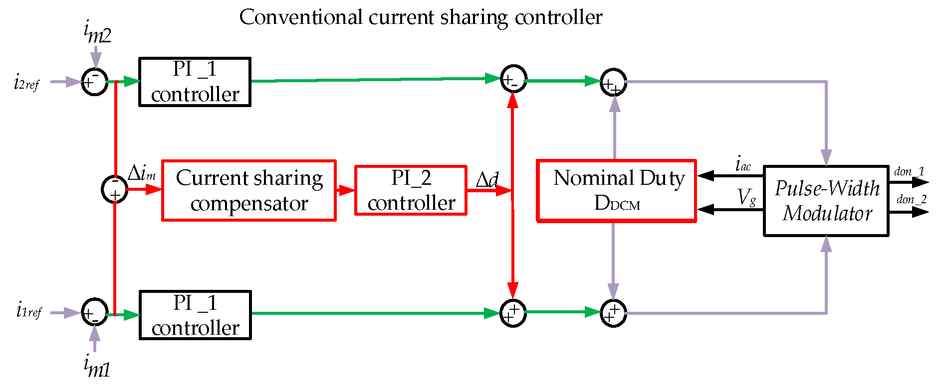
The control diagrams of SMC and PI current controller are illustrated in Figure 5 and Figure 6, respectively. Figure 5 demonstrates the proposed sliding mode current sharing control adopts an open-loop control. The current sharing is achieved through sensing and controlling the primary switch currents. In order to meet the consistency of the comparison conditions, the current open-loop control mode is adopted in the conventional PI current sharing controller; the PI control diagram is indicated in Figure 6. It shows the PI current sharing controller consists of 3 PI controllers, which increases the design complexity. The designed sliding mode control law u is presented as Equation (17), the parameters matrix A, B can be obtained from the system parameters. From Equation (19), the coefficients of kp,smc and ki,smc refer to and , respectively. In order to meet the condition of asymptotic convergence, the parameters of and are obtained from , = 0.08, = 0.08, and K = I, where I is the unit matrix.
In order to compare dynamic performances between the PI current sharing and the proposed sliding mode current sharing controller, the two cases are designed as follows. The output voltage Vrms is 220 V:
Case 1: The two converters, Flyback 1 and Flyback 2, have the same parameters in the flyback micro-inverter. The output power Pout is changed from 200 W (80% P0) to 125 W (50% P0) at 0.06 s.
Figure 7 shows the waveform of the output grid current iac and reference signal iac_ref of the interleaved flyback micro-inverter with the PI current sharing controller. There are large current ripples in simulation’s waveform. When the output power decreases to 50% P0, the PI controller regulates the output current to track the desired output current, which shows the ability to reject the disturbance, but oscillation still exists. Through the Fast Fourier Transformation (FFT) analysis, when 0.02 s ≤ t ≤ 0.06 s, the THDs of output current is 6.43%; when 0.06 s < t ≤ 0.1 s, the THDs of output current is 6.58%.
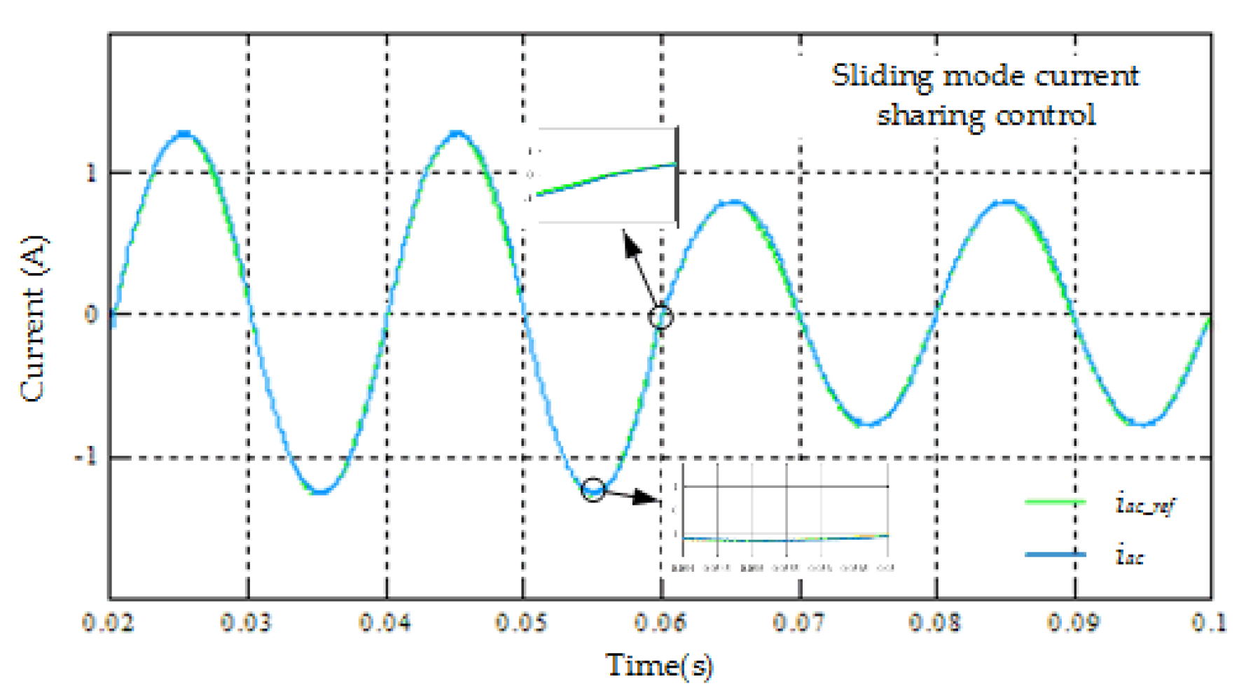
Figure 8 shows the waveforms of the output grid current iac of the interleaved flyback micro-inverter and reference signal iac_ref with the sliding mode current sharing controller. When the output power Pout changes from 80% P0 to 50% P0, the effective value of the output current iac is from 0.908 A to 0.565 A, where only a small transient current is observed in the current waveforms. Through the FFT analysis, when 0.02 s ≤ t ≤ 0.06 s, the output current THDs of the SMC controller is 2.97%; when 0.06 s < t ≤ 0.1 s, the output current THDs of the SMC controller is 2.45%.
The simulation results show that the proposed SMC controller has stronger robustness to solve the output imbalance caused by disturbance when the output power decreases. Moreover, compared with the PI controller, the output current iac of the proposed SMC controller has lower THDs.
Case 2: The two converters, Flyback 1 and Flyback 2, have different parameters in the flyback micro-inverter. The output power Pout is also changed from 200 W (80% P0) to 125 W (50% P0) at 0.06 s. The different parameters are given in Table 3.
Figure 9 describes the waveform of the output grid current iac of the interleaved flyback micro-inverter using the PI current sharing controller, which tracks the reference current Iref well. The output current ripple becomes large when the output current is biggest. As the output power reduces to 50% P0, the output current stays away from the balance point and then converges in short time. Through the FFT analysis, when 0.02 < t < 0.06, the output current THDs of the PI controller are 6.85%; when 0.06 ≤ t ≤ 0.1 s, the output current THDs of the PI controller are 6.87%.
Figure 10 shows the waveform of the output grid current iac of interleaved flyback micro-inverter using the proposed sliding mode current sharing controller. There is a small current transient when output power decreases to 125 W. Through the FFT analysis, when 0.02 < t < 0.06, the THD of output current is 3.44%; when 0.06 ≤ t ≤ 0.1 s, the THD of output current is 2.83%. The results of Figure 9 and Figure 10 confirm that SMC has better robustness than the PI controller when a parameter imbalance exists.
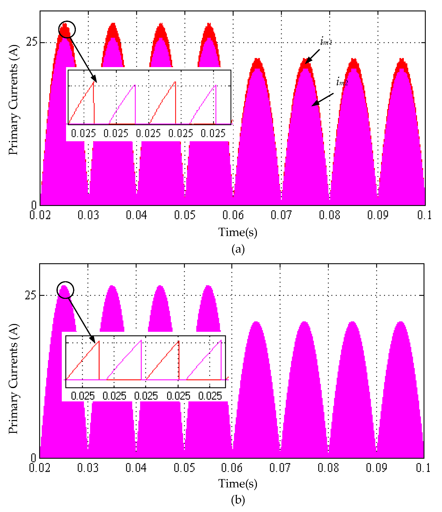
Figure 11a,b demonstrates the waveforms of primary currents im1 and im2 with the PI controller, and those with the sliding mode controller, respectively. It is very clear that the peak current difference between the two primary currents is about 0.318 A with the PI current sharing control, while that with the sliding mode controller is much less, and its value is approximate 0.05 A. From the results, it is found that the proposed controller achieved better current sharing in comparison to the PI controller, which would avoid one of the converters being overloaded, resulting in lower efficiency and reliability of the system, and even reducing the life of hardware. Figure 12 shows the current sharing errors after two current sharing controllers, and the results indicate that the current sharing errors with both controllers are almost negligible, but the THDs of the output current with the PI controller are bigger.
In summary, the simulation results show that the proposed SMC has good robustness to solve output imbalance caused by coupling, parameter inconsistency and disturbance. No matter whether the parameters are identical or not, compared with the PI current sharing controller, the proposed SMC tracks a sinusoidal reference effectively and achieves current sharing. Simultaneously, it has stronger anti-interference ability when the load power changes. In addition to that, there is a lower THD of iac when the proposed SMC is applied. The detailed simulation results are presented in Table 4.
5. Conclusions
This paper has proposed a current sharing control approach for the DCM interleaved flyback micro-inverter. To do this, an accurate fourth-order model has firstly been built up, which is used to analyze the output imbalance problem caused by coupling and mismatched parameters between two flyback converters, such as the equivalent series resistances and magnetizing inductances of the primary/secondary magnetizing inductance. The accuracy of the proposed model has been analyzed through comparing it to the third-order and second-order models, and the analysis results have shown that the proposed model is more accurate than the existing models.
Then, a sliding mode current sharing controller based on the full-fourth-order model has been developed, which solves the output imbalance caused by parameter imbalance and disturbance. The developed sliding mode controller comprises two parts: the feed-forward part, which can improve the tracking bandwidth and reject the measured disturbance, and the feedback part, which is in a form of PI. Thus, the proposed sliding mode controller can use the conventional PI blocks for current sharing. Since the parameters of the sliding control law can be designed by the proposed model and Lyapunov energy function, it is convenient to design compared to the PI current sharing controllers with four gains.
Finally, simulation studies were carried out in MATLAB/Simulink to validate the model accuracy, and the sliding mode current sharing controller. Results showed that the sliding mode controller tracks sinusoidal reference signals smoothly, and controls the current sharing between two flyback converters effectively when compared to the PI controllers.
Author Contributions
All the author contributed to this work. X.T. designed this study, analysis, implemented simulations, and wrote the first draft of the paper. M.D. and L.W. contributed the project administration and checked the overall logic of this work. D.S. contributed to providing important suggestions and writing-review. L.L. contributed to giving helpful suggestions for simulations and English grammar. M.Z. contributed to the discussion of this study.
Funding
This work was supported in part by National Natural Science Foundation of China (Grant NO.51677194).
Conflicts of Interest
The authors declare no conflict of interest.
Nomenclature
| Cpv | input capacitor | mF |
| Vpv | PV voltage | V |
| n | the transformer turns ratio | - |
| Lm1, Lm2 | the primary magnetizing inductances of the transformer | uH |
| im1, im2 | the primary currents of the transformer | A |
| is1, is2 | the secondary currents of the transformer | A |
| Lf | the filter inductor | uH |
| Cf | filter capacitor | uH |
| Rp1, Rp2 | ESRs of the primary magnetizing inductance | Ω |
| Rs1, Rs2 | ESRs of the secondary magnetizing inductance | Ω |
| Rf | ESR of the output filter inductor | Ω |
| iac | output current | A |
| iac_ref | the reference of iac | A |
| fs | switching frequency | kHZ |
| fg | frequency of gird | HZ |
| Vg | grid voltage | V |
| P0 | rated power | W |
| D | main MOSFET duty cycle | - |
| , | the average and small signal of x in one switching period | - |
| H | the number of steady-state subinterval | - |
| Ak and Bk | steady state equations in k-interval | - |
| di(i = 1, …, k) | k-interval duty cycle | - |
| revised matrix | - | |
| nL | the number of inductor | - |
| don_1, don_2 | duty cycles of switches Q1 and Q2 when they are on | - |
| doff_1, doff_2 | the time intervals from turn-off of switches Q1 and Q2 to the decreasing to zero of transformer inductor currents | - |
| ADCM, BDCM, WDCM | The coefficient matrixes of the proposed model | - |
| Gdt4, Gdt3_1, Gdt3_2, Gd2 | The transfer functions of the proposed fourth-order model, the reduced to third-order model, the third-order model based on single-phase flyback converter and second-order model | - |
| a2 ~ a0, b3 ~ b0, c1 ~ c0, , j2 ~ j0, f2 ~ f0, h2 ~ h0 | the coefficients of Gdt4, Gdt3_1, Gdt_2 and Gd2 | - |
| e1 e2 | tracking errors of Flyback1 and Flyabck2 | A |
| α | current sharing error | A |
| I1ref, I2ref | the primary current references of Flyback1 and Flyback2 converters | A |
| S | the sliding surface | - |
| λ | sliding coefficient | - |
| ρ | observer gain matrix | - |
| coefficient matrix for limiting integral gain | - | |
| K | positive definite feedback gain matrix | - |
| kp,smc, ki,smc | proportional and integral of sliding mode law | - |
Appendix A.
The parameters ADCM, BDCM and WDCM of Equation (6) are given
The coefficient parameters a2 ~ a0, b3 ~ b0 of Gdt4, c1 ~ c0, j2 ~ j0 and f2 ~ f0 of Gdt3_1, and h2 ~ h0 of Gd2 are given as.
- a2 ~ a0:
- b3 ~ b0:
- c1 ~ c0:
- j2 ~ j0:
- f2 ~ f0:
- h2 ~ h0:
The parameters of matrix A, B shown in Equation (11) are given as
Appendix B. Robustness of the Proposed SMC
Remark 1.
The Lyapunov energy function V satisfies the condition of being lower bounded, so the V is constructed as
It is assumed that the SMC controller for current sharing is stable in the interleaved flyback micro-inverter. V represents the total energy of the system, which depends on the sliding surface dynamics by the STS term, also depends on the adaptive disturbance error by the term.
Remark 2.
The derivative of the Lyapunov function must be negative semi-definite to generate a stable SMC control law. As a result, asymptotic stability of the overall system may be achieved.
It should be noted that the disturbance is regarded as a slowly varying quantity, so that the derivative of the actual disturbance is considered to be zero, = 0. Then, the derivative of the Lyapunov energy function is obtained from Equation (A31) and computed as:
According to Equations (15) and (16), Equation (A32) can be expressed as
In order to meet the requirement of , the matrix should be designed to satisfy the condition of < 0, which makes the disturbance observable. Next, to ensure the system asymptotically converges ( satisfies the condition of negative semi-definite). Then the derivative of the Lyapunov energy function is designed as follows:
Substituting Equation (16) into Equation (A34), the SMC control law u is obtained, which is given in Equation (18).
Remark 3.
The should satisfy the condition of being uniformly continuous in time, or should satisfy the condition of being bounded.
According to Equation (A34), the differential of is given as
In order to satisfy the boundary condition, the S and should be bounded.
Next, let Equations (13) and (15) be substituted into Equation (A34), then
From Equation (A36), it is shown that the sliding surface S and differential of S are bounded, since the term of is abounded. Therefore, it is proved that satisfies the condition of being bounded, since S and are bounded. So satisfies the condition of being uniformly continuous in time.
According to Barbalat’s lemma [46], when three remarks are satisfied, it ensures that all the errors can converge to the sliding surface. Finally, it is proved that the errors e1, e2 and α can converge to a zero point and the designed controller is stable.
References
- Chiacchio, F.; Famoso, F.; D’Urso, D.; Brusca, S.; Aizpurua, J.I.; Cedola, L. Dynamic performance evaluation of photovoltaic power plant by stochastic hybrid fault tree automaton model. Energies 2018, 11, 306. [Google Scholar] [CrossRef]
- Song, D.; Yang, J.; Fan, X.; Liu, Y.; Liu, A.; Chen, G.; Joo, Y. Maximum power extraction for wind turbines through a novel yaw control solution using predicted wind directions. Energy Convers. Manag. 2018, 157, 589–599. [Google Scholar] [CrossRef]
- Huang, L.; Qiu, D.; Xie, F.; Chen, Y.; Zhang, B. Modeling and stability analysis of a single-phase two-stage grid-connected Photovoltaic System. Energies 2017, 10, 2176. [Google Scholar] [CrossRef]
- Wang, Y.; Gan, C.; Ni, K.; Li, X.; Tang, H.; Yang, Y. A multifunctional isolated and non-isolated dual mode converter for renewable energy conversion applications. Energies 2017, 10, 1980. [Google Scholar] [CrossRef]
- Voglitsis, D.; Papanikolaou, N.; Kyritsis, A.C. Incorporation of Harmonic Injection in an Interleaved Flyback Inverter for the Implementation of an Active Anti-Islanding Technique. IEEE Trans. Power Electron. 2017, 32, 8526–8543. [Google Scholar] [CrossRef]
- Rezaei, M.A.; Kui-Jun, L.; Huang, A.Q. A high-efficiency flyback micro-inverter with a new adaptive snubber for photovoltaic applications. IEEE Trans. Power Electron. 2016, 31, 318–327. [Google Scholar] [CrossRef]
- Park, J.; Roh, Y.S.; Moon, Y.J.; Yoo, C. A CCM/DCM dual-mode synchronous rectification controller for a high-efficiency flyback converter. IEEE Trans. Power Electron. 2014, 29, 768–774. [Google Scholar] [CrossRef]
- Brockveld, S.L.; Waltrich, G. Boost-flyback converter with interleaved input current and output voltage series connection. IET Power Electron. 2018, 11, 1463–1471. [Google Scholar] [CrossRef]
- Cheng, H.L.; Chang, Y.N.; Chang, C.H.; Hsieh, S.Y.; Cheng, C.A. A novel high-power-factor AC/DC LED driver with dual Flyback converters. IEEE J. Emerg. Sel. Top. Power Electron. 2018. [Google Scholar] [CrossRef]
- Hasan, R.; Mekhilef, S.; Seyedmahmoudian, M.; Horan, B. Grid-connected isolated PV microinverters: A review. Renew. Sustain. Energy Rev. 2017, 67, 1065–1080. [Google Scholar] [CrossRef]
- Getachew, B.W.; Asegid, B.K. Autotransformer fed traction power supply system: analysis, modeling and simulation. Glob. Energy Interconnect. 2018, 1, 187–196. [Google Scholar]
- Sher, H.A.; Addoweesh, K.E.; Al Haddad, K. An efficient and cost-effective hybrid MPPT method for a photovoltaic flyback micro-inverter. IEEE Trans. Sustain. Energy 2017, 9, 1137–1141. [Google Scholar] [CrossRef]
- Edwin, F.F.; Xiao, W.; Khadkikar, V. Dynamic modeling and control of interleaved flyback module-integrated converter for PV power applications. IEEE Trans. Ind. Electron. 2014, 61, 1377–1388. [Google Scholar] [CrossRef]
- Gonzalez, L.G.; Vanegas, P.; Sempertegui, R.; Carranza, O. Peak control current in boundary conduction mode and discontinuous conduction mode for inverter with flyback topology. In Proceedings of the IEEE 2015 IEEE Workshop on Power Electronics and Power Quality Applications (PEPQA), Bogota, Colombia, 2–4 June 2015. [Google Scholar]
- Kim, Y.H.; Ji, Y.H.; Kim, J.G.; Jung, Y.C.; Won, C.Y. A new control strategy for improving weighted efficiency in photovoltaic AC module-type interleaved flyback inverters. IEEE Trans. Power Electron. 2013, 28, 2688–2699. [Google Scholar] [CrossRef]
- Zhiliang, Z.; Xiao, F.H.; Yan, F.L. An optimal control method for photovoltaic grid-tied-interleaved flyback microinverters to achieve high efficiency in wide load range. IEEE Trans. Power Electron. 2013, 28, 5074–5087. [Google Scholar]
- Kamil, M. Grid-Connected Solar Microinverter Reference Design Using a dsPIC Digital Signal Controller; Microchip Application Notes AN1338; Microchip Technology Inc.: Chandler, AZ, USA, 2010. [Google Scholar]
- Kamil, M. Grid-Connected Solar Microinverter Reference Design Using a dsPIC Digital Signal Controller; Microchip Application Notes AN1444; Microchip Technology Inc.: Chandler, AZ, USA, 2010. [Google Scholar]
- Gao, M.; Chen, M.; Zhang, C.; Qian, Z. Analysis and implementation of an improved flyback inverter for photovoltaic AC module applications. IEEE Trans. Power Electron. 2014, 29, 3428–3444. [Google Scholar] [CrossRef]
- Kim, J.W.; Jung, P.M.; Gun, W.M. Analysis and design of a single-switch forward-flyback two-channel LED driver with resonant-blocking capacitor. IEEE Trans. Power Electron. 2016, 31, 2314–2323. [Google Scholar] [CrossRef]
- Zengin, S.; Fırat, D.; Mutlu, B. Volt-second-based control method for discontinuous conduction mode flyback micro-inverters to improve total harmonic distortion. IET Power Electron. 2013, 6, 1600–1607. [Google Scholar] [CrossRef]
- Sun, J.; Mitchell, D.M.; Greuel, M.F.; Krein, P.T.; Bass, R.M. Averaged modeling of PWM converters operating in discontinuous conduction mode. IEEE Trans. Power Electron. 2001, 16, 482–492. [Google Scholar] [Green Version]
- Li, Q.; Yao, K.; Song, J.; Xu, H.; Han, Y. A series diode method of suppressing parasitic oscillation for boost PFC converter operated in discontinuous conduction mode. IEEE Trans. Power Electron. 2018, 33, 407–424. [Google Scholar] [CrossRef]
- Delavaripour, H.; Mirzaeian Dehkordi, B.; Adib, E.; Abootorabi Zarchi, H. Dynamic model development and control for multiple-output flyback converters in DCM and CCM. Int. J. Circ. Theory Appl. 2018, 46, 1228–1248. [Google Scholar] [CrossRef]
- Mira, M.C.; Zhang, Z.; Knott, A.; Andersen, M.A. Analysis, design, modeling, and control of an interleaved-boost full-bridge three-port converter for hybrid renewable energy systems. IEEE Trans. Power Electron. 2017, 32, 1138–1155. [Google Scholar] [CrossRef]
- Chen, M.; Gao, F.; Li, R.; Li, X. A dual-input central capacitor dc/dc converter for distributed photovoltaic architectures. IEEE Trans. Ind. Appl. 2017, 53, 305–318. [Google Scholar] [CrossRef]
- Agrawal, A.; Shrivastava, A.; Jana, K.C. Uniform model and analysis of PWM DC-DC converter for discontinuous conduction mode. IETE J. Res. 2017, 1–13. [Google Scholar] [CrossRef]
- Kim, H.; Lee, J.S.; Lai, J.S.; Kim, M. Iterative learning controller with multiple phase-lead compensation for dual-mode flyback inverter. IEEE Trans. Power Electron. 2017, 32, 6468–6480. [Google Scholar] [CrossRef]
- Wang, H.; Yang, C.; Yan, F.L. A passive-impedance-matching technology to achieve automatic current sharing for a multiphase resonant converter. IEEE Trans. Power Electron. 2017, 32, 9191–9209. [Google Scholar] [CrossRef]
- Wang, H.; Chen, Y.; Qiu, Y.; Fang, P.; Zhang, Y.; Wang, L.; Yang, Z.A. Common capacitor multiphase LLC converter with passive current sharing ability. IEEE Trans. Power Electron. 2018, 33, 370–387. [Google Scholar] [CrossRef]
- Shi, J.; Liu, T.; Cheng, J.; He, X. Automatic current sharing of an input-parallel output-parallel (IPOP)-connected DC–DC converter system with chain-connected rectifiers. IEEE Trans. Power Electron. 2015, 30, 2997–3016. [Google Scholar] [CrossRef]
- He, J.; Yun, W.L. Analysis, design, and implementation of virtual impedance for power electronics interfaced distributed generation. IEEE Trans. Ind. Appl. 2011, 47, 2525–2538. [Google Scholar] [CrossRef]
- Sun, Y.; Hou, X.; Yang, J.; Han, H.; Su, M.; Guerrero, J.M. New perspectives on droop control in AC microgrid. IEEE Trans. Ind. Electron. 2017, 64, 5741–5745. [Google Scholar] [CrossRef]
- Su, M.; Liu, Z.; Sun, Y.; Han, H.; Hou, X. Stability analysis and stabilization methods of DC microgrid with multiple parallel-connected DC-DC converters loaded by CPLs. IEEE Trans. Smart Grid 2018, 9, 132–142. [Google Scholar] [CrossRef]
- Liu, Z.; Su, M.; Sun, Y.; Han, H.; Hou, X.; Guerrero, J.M. Stability analysis of DC microgrids with constant power load under distributed control methods. Automatica 2018, 90, 62–72. [Google Scholar] [CrossRef]
- Ye, T.; Dai, N.; Lam, C.S.; Wong, M.C.; Guerrero, J.M. Analysis, Design, and Implementation of a Quasi-proportional-resonant controller for a multifunctional capacitive-coupling grid-connected inverter. IEEE Trans. Ind. Appl. 2016, 52, 4269–4280. [Google Scholar] [CrossRef]
- Davoudi, A.; Juri, J.; Tom, D.R. Numerical state-space average-value modeling of PWM DC-DC converters operating in DCM and CCM. IEEE Trans. Power Electron. 2006, 21, 1003–1012. [Google Scholar] [CrossRef]
- Sucu, M. Parametric Average Value Modeling of Flyback Converters in CCM and DCM Including Parasitics and Snubbers. Master’s Thesis, University of British Columbia, Vancouver, BC, Canada, 2011. [Google Scholar]
- Fonkwe, E.; James, K. Current distortion around grid zero-volt crossing and open-loop power factor in flyback AC module with a pseudo-DC link. In Proceedings of the 2015 IEEE International Conference on Smart Grid and Clean Energy Technologies (ICSGCE), Offenburg, Germany, 20–23 October 2015. [Google Scholar]
- Kyritsis, A.C.; Tatakis, E.C.; Papanikolaou, N.P. Papanikolaou. Optimum design of the current-source flyback inverter for decentralized grid-connected photovoltaic systems. IEEE Trans. Energy Convers. 2008, 23, 281–293. [Google Scholar] [CrossRef]
- Thang, T.V.; Thao, N.M.; Jang, J.H.; Park, J.H. Analysis and design of grid-connected photovoltaic systems with multiple-integrated converters and a pseudo-dc-link inverter. IEEE Trans. Ind. Electron. 2014, 61, 3377–3386. [Google Scholar] [CrossRef]
- Padmanaban, S.; Ozsoy, E.; Fedák, V.; Blaabjerg, F. Development of sliding mode controller for a modified boost ćuk converter configuration. Energies 2017, 10, 1513. [Google Scholar] [CrossRef]
- Huang, M.; Liu, Y.; Zhang, N.; Xiong, N.; Liu, A.; Zeng, Z.; Song, H. A services routing based caching scheme for cloud assisted CRNs. IEEE Access. 2018, 6, 15787–15805. [Google Scholar] [CrossRef]
- Sencer, B.; Mori, T.; Shamotoc, E. Design and application of a sliding mode controller for accurate motion synchronization of dual servo systems. Control Eng. Pract. 2013, 21, 1519–1530. [Google Scholar] [CrossRef]
- Song, D.; Yang, J.; Cai, Z.; Dong, M.; Joo, Y.H. Model predictive control with finite control set for variable-speed wind turbines. Energy 2017, 126, 564–572. [Google Scholar] [CrossRef]
- Slotine, J.J.E.; Weiping, L. Applied Nonlinear Control; Prentice Hall: Englewood Cliffs, NJ, USA, 1991; Volume 199. [Google Scholar]
Figure 1.
The interleaved flyback mirco-inverter topology.

Figure 2.
PWM and duty cycle for one switching period and the waveforms of im1, is1, im2, and is2 corresponding to switch Q1, Q2 and Duty cycle state.
Figure 2.
PWM and duty cycle for one switching period and the waveforms of im1, is1, im2, and is2 corresponding to switch Q1, Q2 and Duty cycle state.
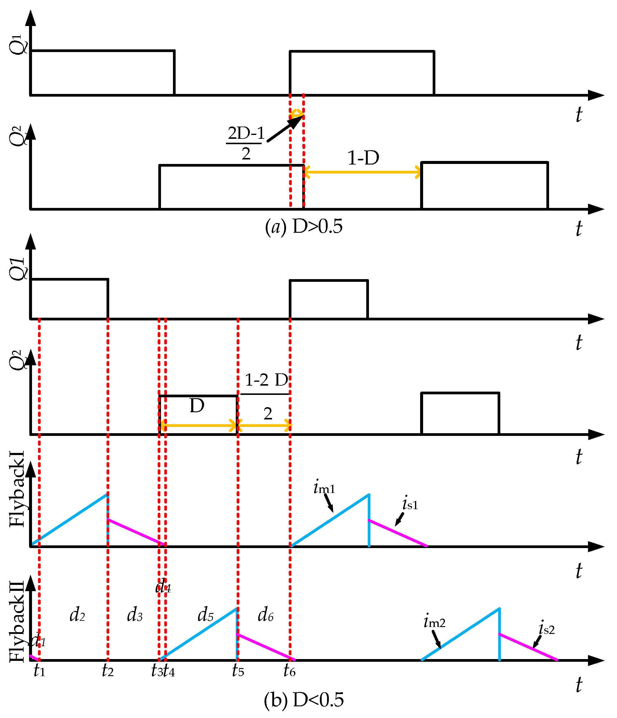
Figure 3.
Equivalent circuits for different intervals in steady-state operation.
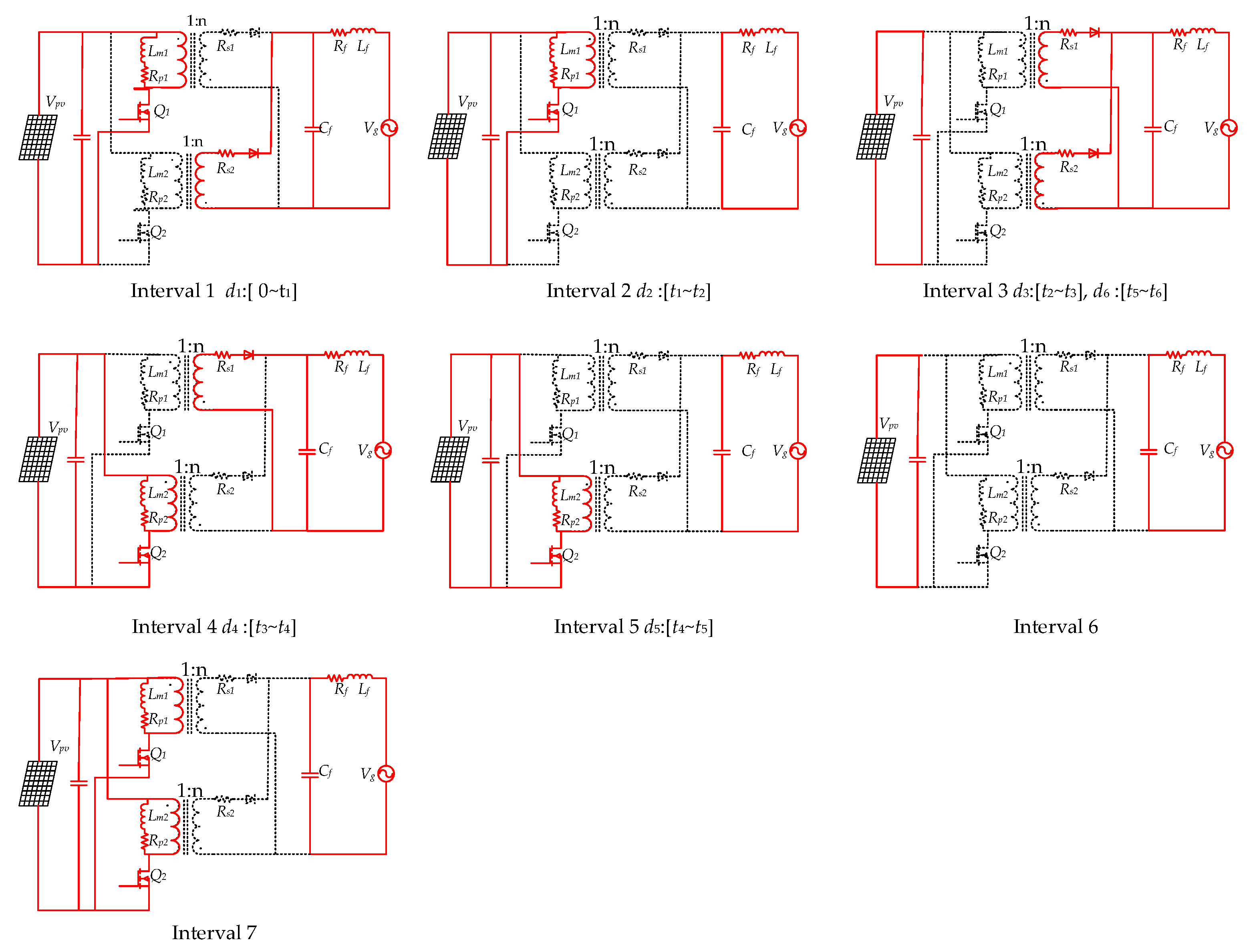
Figure 4.
Flow chart for designing sliding mode current sharing controller.
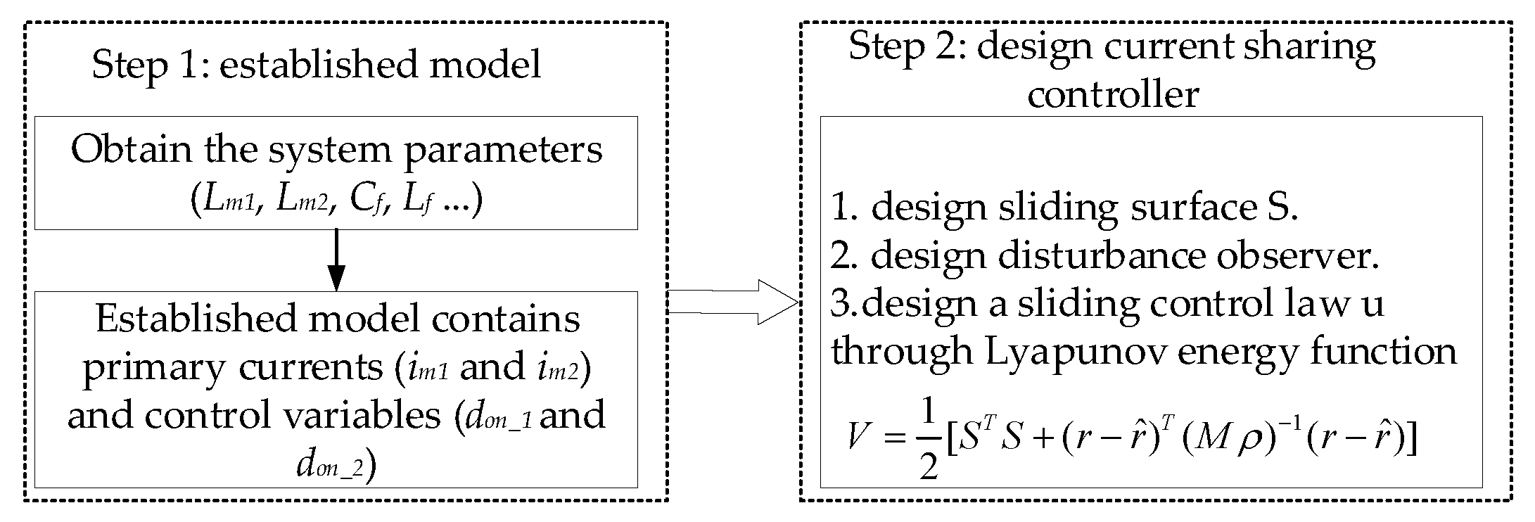
Figure 5.
The SMC control diagram of interleaved flyback micro-inverter in DCM.
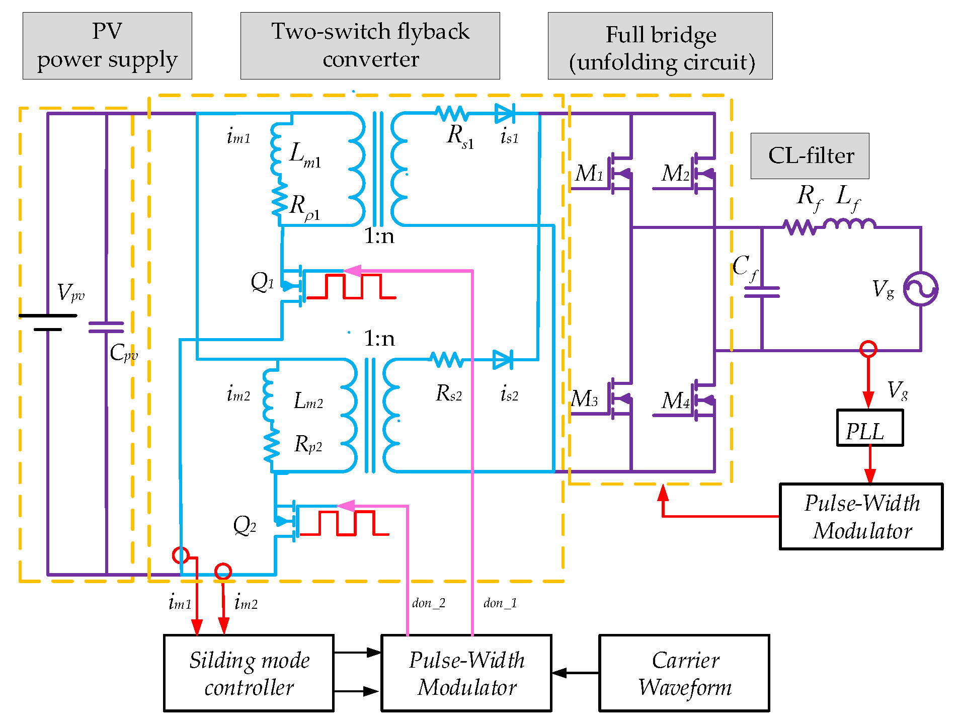
Figure 6.
The PI control diagram of interleaved flyback micro-inverter in DCM.

Figure 7.
Simulation results of case 1: output grid current response of the interleaved flyback micro-inverter controlled by a PI controller.
Figure 7.
Simulation results of case 1: output grid current response of the interleaved flyback micro-inverter controlled by a PI controller.
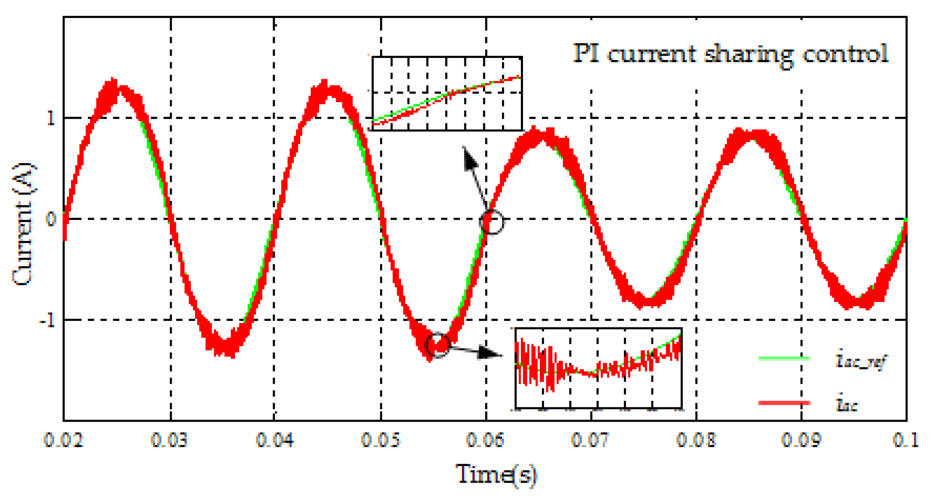
Figure 8.
Simulation results of case 1: output grid current response of the interleaved flyback micro-inverter controlled by a SMC controller.
Figure 8.
Simulation results of case 1: output grid current response of the interleaved flyback micro-inverter controlled by a SMC controller.

Figure 9.
Simulation results of Case 2: output gird current response of interleaved flyback micro-inverter by a PI controller.
Figure 9.
Simulation results of Case 2: output gird current response of interleaved flyback micro-inverter by a PI controller.
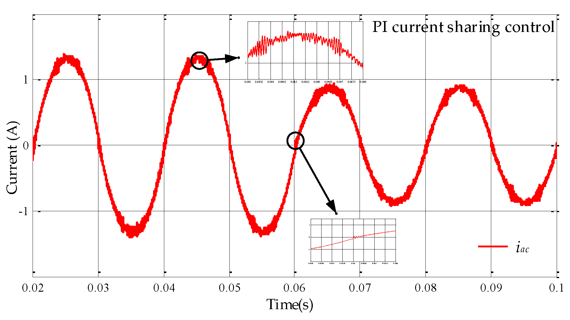
Figure 10.
Simulation results of Case 2: output gird current response of interleaved flyback micro-inverter by a SMC controller.
Figure 10.
Simulation results of Case 2: output gird current response of interleaved flyback micro-inverter by a SMC controller.
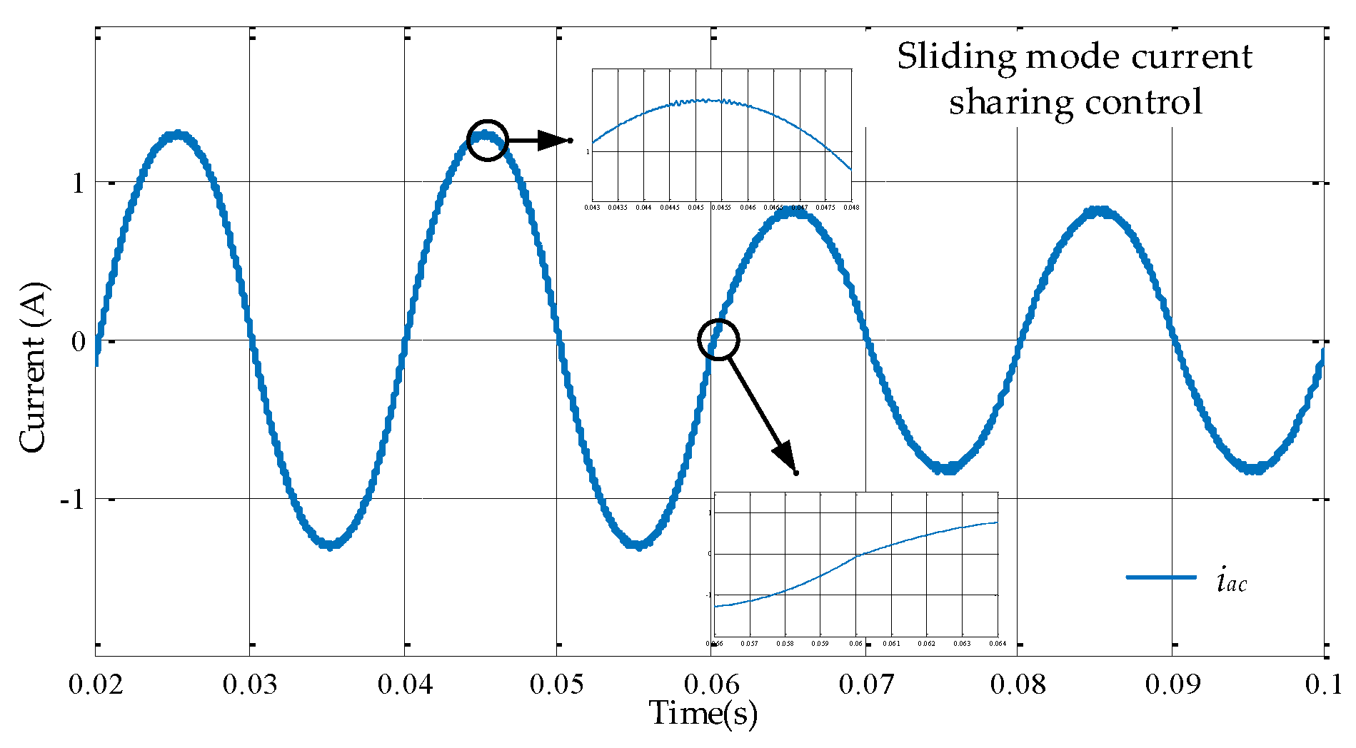
Figure 11.
Waveforms for primary currents by two current sharing controllers: (a) PI current sharing control; (b) sliding mode current sharing control.
Figure 11.
Waveforms for primary currents by two current sharing controllers: (a) PI current sharing control; (b) sliding mode current sharing control.

Figure 12.
The difference of the two primary currents after the two current sharing controllers: (a) PI current sharing control; (b) sliding mode current sharing control.
Figure 12.
The difference of the two primary currents after the two current sharing controllers: (a) PI current sharing control; (b) sliding mode current sharing control.


Table 1.
Circuit steady-state operations.
| Interval | Switch Q1 | Switch Q2 | Diode 1 | Diode 2 |
|---|---|---|---|---|
| 1 | ON | OFF | OFF | ON |
| 2 | ON | OFF | OFF | OFF |
| 3 | OFF | OFF | ON | ON |
| 4 | OFF | ON | ON | OFF |
| 5 | OFF | ON | OFF | OFF |
| 6 | OFF | OFF | OFF | OFF |
| 7 | ON | ON | OFF | OFF |
Table 2.
System parameters.
| Parameters | Value | Parameters | Value |
|---|---|---|---|
| CPV | 11 mF | Rp1, Rp2 | 0.15 Ω |
| Lm1, Lm2 | 6 μH | Rs1, Rs2 | 0.05 Ω |
| Cf | 0.68 μF | Rf | 0.29 Ω |
| Lf | 600 μH | Vg | 220 V |
| n | 6 | fg | 50 Hz |
| fs | 100 kHz | P0 | 250 W |
Table 3.
Different system parameters.
| Parameters | Value | Parameters | Value | Parameters | Value |
|---|---|---|---|---|---|
| Lm1 | 5.8 μH | Rp1 | 0.15 Ω | Rs1 | 0.051 Ω |
| Lm2 | 6.2 μH | Rp2 | 0.18 Ω | Rs2 | 0.085 Ω |
| Ls1 | 216 μH | Ls2 | 223 μH | - | - |
Table 4.
Simulink results.
| Controller | Pout | Case 1 | Case 2 | ||
|---|---|---|---|---|---|
| α | THDs | α | THDs | ||
| the proposed SMC | 200 W | 0.001 | 2.97% | 0.01 | 3.44% |
| PI controller | 200 W | 0.01 | 6.43% | 0.32 | 6.85% |
| the proposed SMC | 150 W | 0.001 | 2.45% | 0.05 | 2.83% |
| PI controller | 150 W | 0.005 | 6.58% | 0.318 | 6.87% |
© 2018 by the authors. Licensee MDPI, Basel, Switzerland. This article is an open access article distributed under the terms and conditions of the Creative Commons Attribution (CC BY) license (http://creativecommons.org/licenses/by/4.0/).
Share and Cite
MDPI and ACS Style
Dong, M.; Tian, X.; Li, L.; Song, D.; Wang, L.; Zhao, M. Model-Based Current Sharing Approach for DCM Interleaved Flyback Micro-Inverter. Energies 2018, 11, 1685. https://doi.org/10.3390/en11071685
AMA Style
Dong M, Tian X, Li L, Song D, Wang L, Zhao M. Model-Based Current Sharing Approach for DCM Interleaved Flyback Micro-Inverter. Energies. 2018; 11(7):1685. https://doi.org/10.3390/en11071685
Chicago/Turabian StyleDong, Mi, Xiaoyu Tian, Li Li, Dongran Song, Lina Wang, and Miao Zhao. 2018. "Model-Based Current Sharing Approach for DCM Interleaved Flyback Micro-Inverter" Energies 11, no. 7: 1685. https://doi.org/10.3390/en11071685
Note that from the first issue of 2016, this journal uses article numbers instead of page numbers. See further details here.