Optimization of Induction Motor Equivalent Circuit Parameter Estimation Based on Manufacturer’s Data

Abstract
:1. Introduction
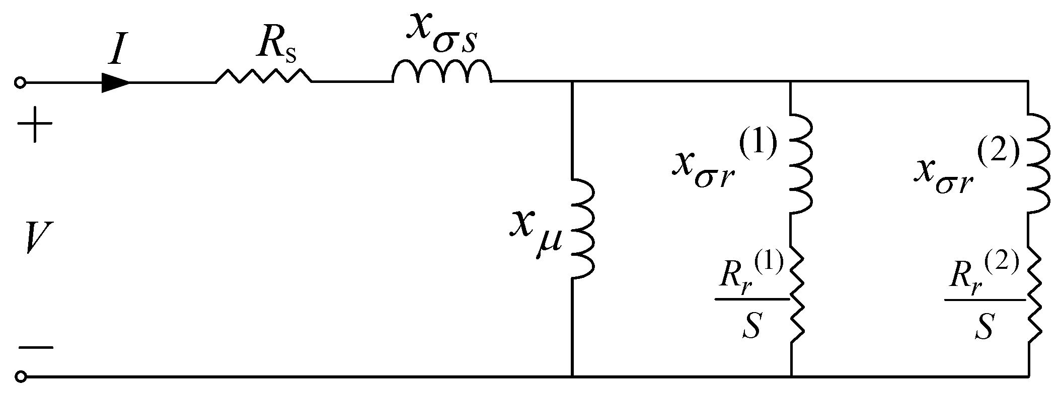
2. Engineering Method for Parameter Estimation
- The resistance () and leakage inductance () of the stator are estimated as:where is the rated slip of the machine and is the ratio of the starting current over the rated current. In [17], the authors calculated the leakage reactance of the stator as one third of the input reactance of the motor, while in [18], the authors stated that the leakage reactance of the stator can be estimated as half of the input reactance.
- Since the core loss is not represented in the model under investigation [17], the values of the given efficiency and power factor are corrected as follows:where η and are the motor efficiency and power factor at full load, respectively. In [18] and [19], the authors proposed a nine-parameter equivalent circuit that does not ignore the core loss in the machine. In that case, this correction step is not needed.
- The reactance of the magnetization branch () is calculated as follows:where the magnetization current () is calculated by:in (6) is the ratio of the pullout torque to the full load torque given in the manufacturer’s data sheet.
- The input resistance and reactance, at the rated slip () and the starting slip (S = 1), are estimated as follows:To increase the accuracy, the ratio of the starting torque to the full load torque () and the ratio of the starting current to the rated current () are corrected as:
- The conductance and susceptance of the rotor, at the rated slip () and the starting slip (S = 1), are determined as follows:
- The resistance and the leakage reactance of the first rotor-circuit branch are calculated as:
- The resistance and leakage reactance of the second rotor-circuit are calculated as:where the conductance () and susceptance () of the second rotor circuit, at starting slip (S = 1), are determined as follows:To validate the above summarized algorithm, the authors in [17] calculated the stator current and torque at different values of slip (rated, critical and starting) and compared them to those values given in the data sheet as follows:The critical slip () is calculated by:where the coefficients of and can be calculated as:Since there are two values for the critical slip calculated by (25), the extraneous value is excluded.
3. Proposed Optimization Procedure
| Algorithm 1: First Stage of Optimization. |
| Step 1: Import induction machine parameters from the manufacturer’s data sheet Step 2: Obtain the parameters of the equivalent circuit of the machine using the Engineering Method Step 3: Minimize the error functions f1, f2 and f3, and iterate until the optimization criterion is met Step 4: Obtain the optimized values for the independent variables C1, C2, C3 and C4 Step 5: Recalculate the parameters of the equivalent circuit using the optimized values of C1, C2, C3 and C4 |
| Algorithm 2: Second Stage of Optimization. |
| Step 1: Import induction machine parameters from the manufacturer’s data sheet Step 2: Obtain the parameters of the equivalent circuit and the results of the first stage of optimization Step 3: Keep C1, C2, C3 and C4 constants in the second stage of optimization Step 4: Minimize the functions f1, f2 and f3 with respect to the new variables: C5, C6, C7 and C8; and find their optimal values Step 5: Recalculate the parameters of the equivalent circuit using the values of C5, C6, C7 and C8 |
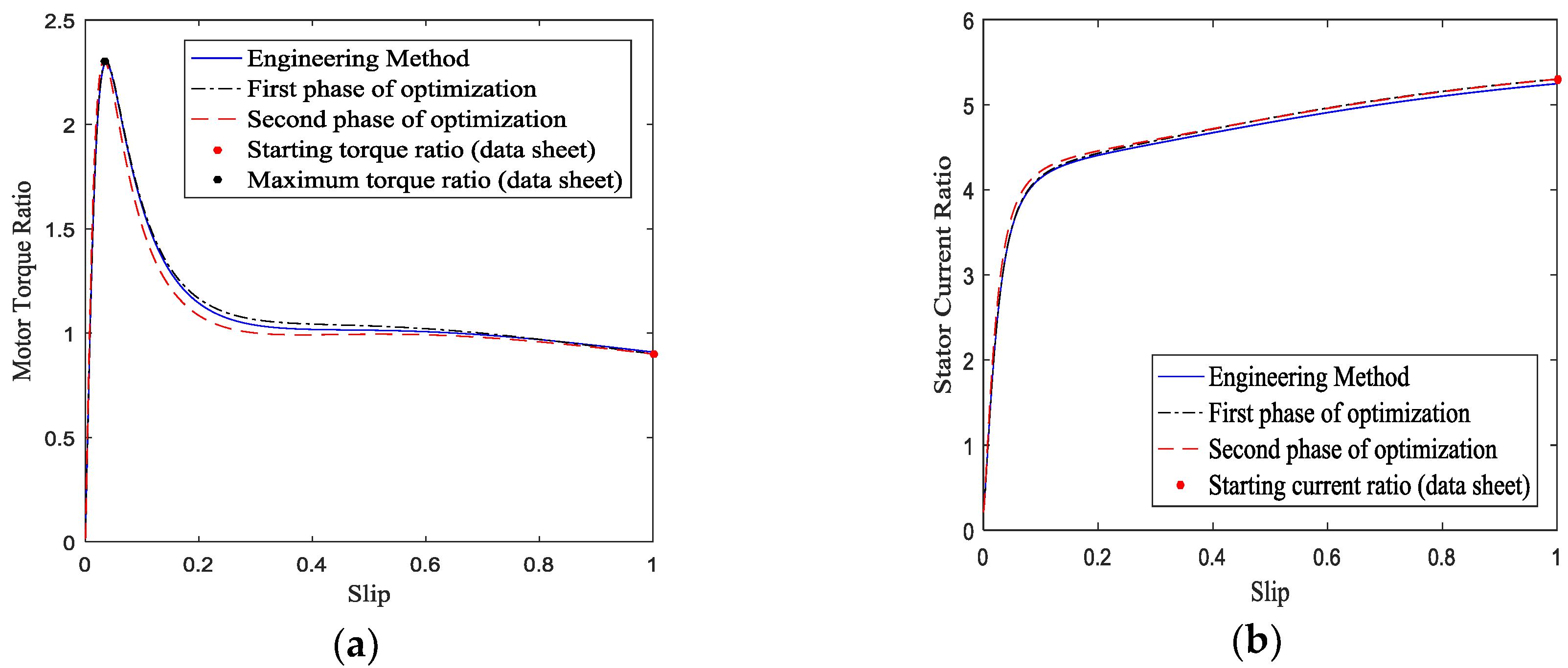
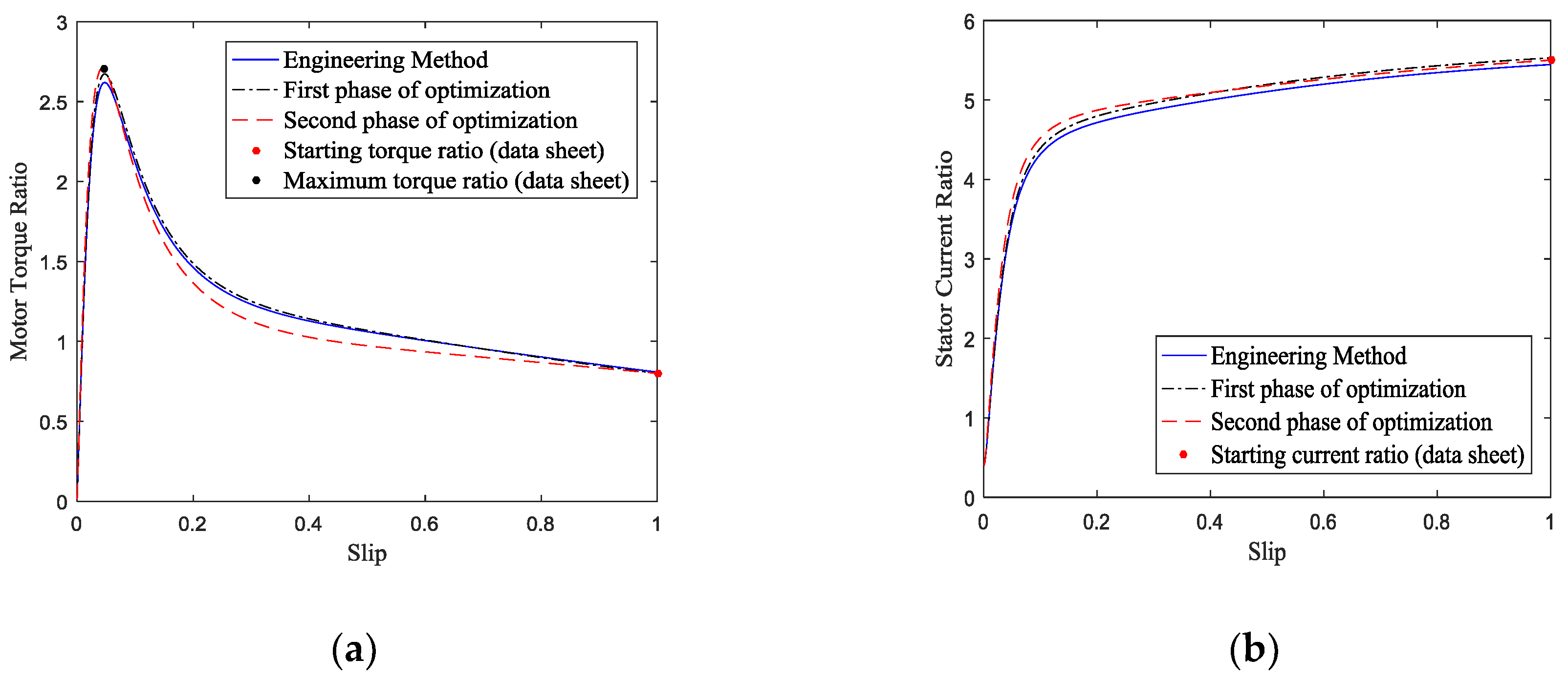
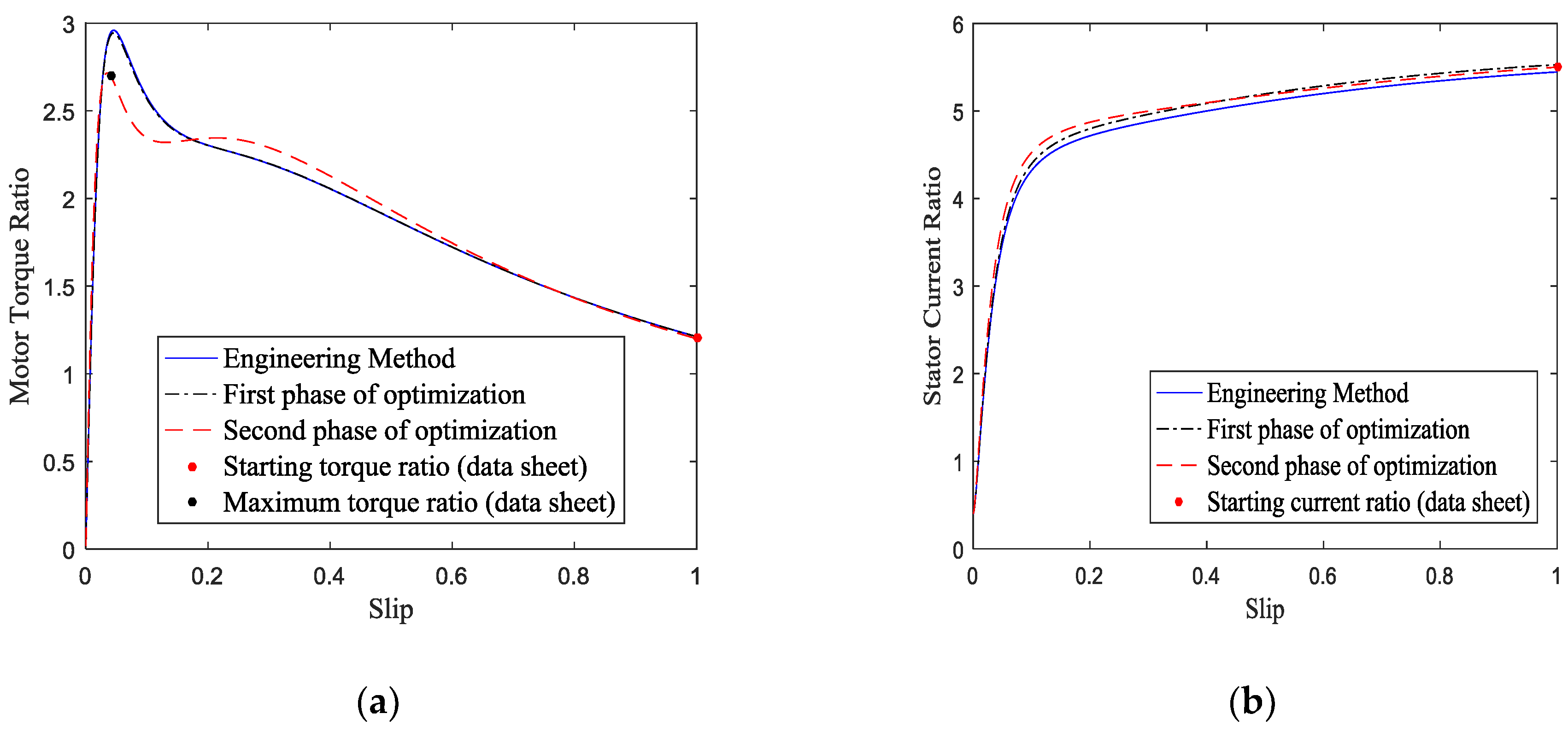
4. Results and Discussion
5. Conclusions
Author Contributions
Funding
Acknowledgments
Conflicts of Interest
Nomenclature
| Resistance of the stator, in per-unit (pu) | |
| Leakage inductance of the stator, pu | |
| Rated slip of the machine | |
| Ratio of the starting current over the rated current | |
| Motor efficiency at full load | |
| Power factor at full load | |
| Corrected value of efficiency | |
| Corrected value of power factor | |
| Reactance of the magnetization branch, pu | |
| Magnetization current, pu | |
| Ratio of the pullout torque to the full load torque | |
| Ratio of the starting torque to the full load torque | |
| Conductance of the rotor, at the rated slip (), pu | |
| Susceptance of the rotor, at the rated slip (), pu | |
| Resistance of the first rotor-circuit branch, pu | |
| Leakage reactance of the first rotor-circuit branch, pu | |
| Resistance of the second rotor-circuit, pu | |
| Leakage reactance of the second rotor-circuit, pu | |
| Conductance of the second rotor circuit, at starting slip (S = 1), pu | |
| Susceptance of the second rotor circuit, at starting slip (S = 1), pu | |
| Critical slip, slip at maximum torque for a given induction machine | |
| Corrected starting torque ratio | |
| Corrected starting current ratio | |
| Weight factors for the error functions, for the optimization process | |
| C1, C2, … C8 | Correction factors of the equivalent circuit parameters |
| Error functions between the calculated values and the real manufacturer values |
Appendix A

| No. | Motor Type | Output Power, kW | Rated Voltage, V | Rated Current, A | Rated Speed, rpm | Efficiency % |
|---|---|---|---|---|---|---|
| 1 | DAZO-1569-8/10 | 800 | 6000 | 94 | 991 | 92.5 |
| 2 | 1LA8 317-2AC | 315 | 415 | 504 | 2979 | 96.6 |
| 3 | 1LA8 315-6AB | 200 | 415 | 338 | 989 | 95.7 |
| 4 | 1PQ8 357-2PC | 500 | 415 | 797 | 2982 | 97.0 |
| 5 | 1PQ8 407-4PB | 675 | 690 | 654 | 1492 | 690 |
| 6 | 1LA8 455-8AD | 560 | 415 | 999 | 744 | 96.3 |
| 7 | 1LA8 458-4AD | 1125 | 690 | 1103 | 1492 | 97.0 |
| 8 | 1PQ8 453-6PD | 630 | 415 | 1080 | 992 | 96.6 |
| 9 | 1PQ8 458-8PD | 670 | 690 | 717 | 744 | 96.5 |
| 10 | 2A3M-2500/6000YXL4 | 2500 | 6000 | 260 | 2975 | 96.8 |
References
- Pustovetov, M.Yu. A mathematical model of the three-phase induction motor in three-phase stator reference frame describing electromagnetic and electromechanical processes. In Proceedings of the Dynamics of Systems, Mechanisms and Machines (Dynamics), Omsk, Russia, 11–13 November 2016; pp. 1–4. [Google Scholar]
- Al-Jufout, S. Modelling of the cage induction motor for symmetrical and asymmetrical modes of operation. Comput. Electr. Eng. 2003, 29, 851–860. [Google Scholar] [CrossRef]
- Asif, M.J.; Shahbaz, T.; Hassan, S.U.; Rizvi, S.T.H. Mathematical modelling of 3-phase induction motor to study the torque vs. speed characteristics using MATLAB Simulink. In Proceedings of the 19th International Multi-Topic Conference (INMIC), Islamabad, Pakistan, 5–6 December 2016; pp. 1–7. [Google Scholar]
- Al-Jufout, S.; Khandakji, K. Dynamic simulation of starting and chopper speed control of wound-rotor induction motor. Int. J. Simul. Syst. Sci. Technol. 2007, 8, 1–7. [Google Scholar]
- IEEE Standard Test Procedure for Polyphase Induction Motors and Generators, in IEEE Std. 112-2004 (Revision of IEEE Std 112-1996), pp.0_1-79, 2004.
- Lee, K.; Frank, S.; Sen, P.K.; Polese, L.G.; Alahmad, M.; Waters, C. Estimation of induction motor equivalent circuit parameters from nameplate data. In Proceedings of the 2012 North American Power Symposium (NAPS), Champaign, IL, USA, 9–11 September 2012; pp. 1–6. [Google Scholar]
- Natarajan, R.; Misra, V.K. Parameter estimation of induction motors using a spreadsheet program on a personal computer. Electr. Power Syst. Res. 1989, 16, 157–164. [Google Scholar] [CrossRef]
- Haque, M.H. Estimation of three-phase induction motor parameters. Electr. Power Syst. 1993, 26, 187–193. [Google Scholar] [CrossRef]
- Boglietti, A.; Cavagnino, A.; Lazzari, M. Computational algorithms for induction-motor equivalent circuit parameter determination—Part I: Resistances and leakage reactances. IEEE Trans. Ind. Electr. 2011, 58, 3723–3733. [Google Scholar] [CrossRef]
- Boglietti, A.; Cavagnino, A.; Lazzari, M. Computational algorithms for induction motor equivalent circuit parameter determination—Part II: Skin effect and magnetizing characteristics. IEEE Trans. Ind. Electr. 2011, 58, 3734–3740. [Google Scholar] [CrossRef]
- Guimarães, J.M.C.; Bernardes, J.V.; Hermeto, A.E.; Bortoni, E.D.C. Parameter determination of asynchronous machines from manufacturer data sheet. IEEE Trans. Energy Convers. 2014, 29, 689–697. [Google Scholar] [CrossRef]
- Haque, M.H. Determination of NEMA design induction motor parameters from manufacturer data. IEEE Trans. Energy Convers. 2008, 23, 997–1004. [Google Scholar] [CrossRef]
- Gastli, A. Identification of induction motor equivalent circuit parameters using the single-phase test. IEEE Trans. Energy Convers. 1999, 14, 51–56. [Google Scholar] [CrossRef]
- Boglietti, A.; Cavagnino, A.; Ferraris, L.; Lazzari, M. Skin effect experimental validations of induction motor squirrel cage parameters. In Proceedings of the 18th International Conference on Electrical Machines, Vilamoura, Portugal, 6–9 September 2008; pp. 1–4. [Google Scholar] [CrossRef]
- Lindenmeyer, D.; Dommel, H.W.; Moshref, A.; Kundur, P. An induction motor parameter estimation method. Electr. Power and Energy Syst. 2001, 23, 251–262. [Google Scholar] [CrossRef]
- Pedra, J.; Corcoles, F. Estimation of induction motor double-cage model parameters from manufacturer data. IEEE Trans. Energy Convers. 2004, 19, 310–317. [Google Scholar] [CrossRef]
- Sivokobylenko, V.F.; Kostenko, V. Electrical Motors Mathematical Modeling of the Power Station Auxiliaries. Donetsk Polytechnic Institute, 1979. [Google Scholar]
- Sivokobylenko, V.F.; Tkachenko, S.N.; Derkachev, S.V. Determining the parameters of equivalent circuits and characteristics of induction motors. Elektrichestvo 2014, 10, 38–44. [Google Scholar]
- Sivokobylenko, V.F. A hybrid equivalent circuit of asynchronous motors with a deep-slot or double-cage rotor. Elektrichestvo 2016, 4, 34–40. [Google Scholar]
- Neklepaev, B.N.; Kruchkov, I.P. Electrical Part of Electrical Stations and Substations, Kiev, Ukraine. Energy 1987. [Google Scholar]
- Reliability with Higher Efficiency; Large LV Motors Type 1LA8/1PQ8-(250 to 1250kW); Siemens, Thane, India, Technical Datasheet. August 2008. Available online: http://w3.siemens.co.in/drives/in/en/motor/ac-motor/Pages/N-compact-Series-Motors.aspx (accessed on 22 February 2017).


| No. | Motor Type | Source of Data | Error, % | |||||
|---|---|---|---|---|---|---|---|---|
| 1. | DAZO-1569-8/10 | Data sheet | 5.500 | 0.800 | 2.700 | 1.000 | 1.000 | 2.991 |
| Engineering Method | 5.445 | 0.808 | 2.619 | |||||
| 2. | 1LA8 317-2AC | Data sheet | 7.000 | 1.800 | 2.800 | 1.000 | 1.000 | 1.007 |
| Engineering Method | 6.930 | 1.818 | 2.828 | |||||
| 3. | 1LA8 315-6AB | Data sheet | 6.500 | 2.000 | 2.500 | 1.000 | 1.000 | 3.346 |
| Engineering Method | 6.435 | 2.020 | 2.584 | |||||
| 4. | 1PQ8 357-2PC | Data sheet | 6.500 | 1.800 | 2.600 | 1.000 | 1.000 | 0.703 |
| Engineering Method | 6.435 | 1.818 | 2.618 | |||||
| 5. | 1PQ8 407-4PB | Data sheet | 6.800 | 1.900 | 2.700 | 1.000 | 1.000 | 0.790 |
| Engineering Method | 6.732 | 1.919 | 2.721 | |||||
| 6. | 1LA8 455-8AD | Data sheet | 7.000 | 1.200 | 2.700 | 1.000 | 1.000 | 9.113 |
| Engineering Method | 6.930 | 1.212 | 2.946 | |||||
| 7. | 1LA8 458-4AD | Data sheet | 6.800 | 0.900 | 2.500 | 1.000 | 1.000 | 6.463 |
| Engineering Method | 6.732 | 0.909 | 2.662 | |||||
| 8. | 1PQ8 453-6PD | Data sheet | 6.500 | 1.200 | 2.500 | 1.000 | 1.000 | 5.779 |
| Engineering Method | 6.435 | 1.212 | 2.644 | |||||
| 9. | 1PQ8 458-8PD | Data sheet | 6.500 | 1.000 | 2.600 | 1.000 | 1.000 | 7.710 |
| Engineering Method | 6.435 | 1.010 | 2.800 | |||||
| 10. | 2A3M-2500/6000YXL4 | Data sheet | 5.300 | 0.900 | 2.300 | 1.000 | 1.000 | 0.274 |
| Engineering Method | 5.247 | 0.909 | 2.294 | |||||
| No. | Motor Type | Method | C1 | C2 | C3 | C4 | Error, % | ||
|---|---|---|---|---|---|---|---|---|---|
| 1. | DAZO-1569-8/10 | Engineering | 1.000 | 3.000 | 0.990 | 1.010 | 1.000 | 1.000 | 2.991 |
| 1st optimization stage | 0.900 | 2.002 | 1.005 | 1.000 | 0.510 | 0.030 | 1.020 | ||
| 2. | 1LA8 317-2AC | Engineering | 1.000 | 3.000 | 0.990 | 1.010 | 1.000 | 1.000 | 1.007 |
| 1st optimization stage | 1.100 | 2.995 | 0.998 | 1.000 | 0.240 | 0.020 | 0.800 | ||
| 3. | 1LA8 315-6AB | Engineering | 1.000 | 3.000 | 0.990 | 1.010 | 1.000 | 1.000 | 3.346 |
| 1st optimization stage | 1.100 | 2.999 | 0.990 | 1.001 | 0.990 | 0.130 | 2.760 | ||
| 4. | 1PQ8 357-2PC | Engineering | 1.000 | 3.000 | 0.990 | 1.010 | 1.000 | 1.000 | 0.703 |
| 1st optimization stage | 1.100 | 3.000 | 0.999 | 1.000 | 0.120 | 0.010 | 0.540 | ||
| 5. | 1PQ8 407-4PB | Engineering | 1.000 | 3.000 | 0.990 | 1.010 | 1.000 | 1.000 | 0.790 |
| 1st optimization stage | 1.099 | 2.993 | 0.999 | 1.000 | 0.130 | 0.010 | 0.640 | ||
| 6. | 1LA8 455-8AD | Engineering | 1.000 | 3.000 | 0.990 | 1.010 | 1.000 | 1.000 | 9.113 |
| 1st optimization stage | 1.100 | 3.000 | 0.990 | 1.010 | 1.000 | 0.990 | 8.560 | ||
| 7. | 1LA8 458-4AD | Engineering | 1.000 | 3.000 | 0.990 | 1.010 | 1.000 | 1.000 | 6.463 |
| 1st optimization stage | 1.100 | 3.000 | 0.990 | 1.006 | 1.000 | 0.570 | 6.170 | ||
| 8. | 1PQ8 453-6PD | Engineering | 1.000 | 3.000 | 0.990 | 1.010 | 1.000 | 1.000 | 5.779 |
| 1st optimization stage | 1.100 | 3.000 | 0.990 | 1.005 | 1.000 | 0.500 | 5.340 | ||
| 9. | 1PQ8 458-8PD | Engineering | 1.000 | 3.000 | 0.990 | 1.010 | 1.000 | 1.000 | 7.710 |
| 1st optimization stage | 1.100 | 3.000 | 1.009 | 0.990 | 1.000 | 0.900 | 7.200 | ||
| 10. | 2A3M-2500/6000YXL4 | Engineering | 1.000 | 3.000 | 0.990 | 1.010 | 1.000 | 1.000 | 0.274 |
| 1st optimization stage | 1.048 | 2.692 | 1.000 | 1.000 | 0.000 | 0.000 | 0.010 | ||
| No. | Motor Type | Method | C1 | C2 | C3 | C4 | C5 | C6 | C7 | C8 | Error, % | ||
|---|---|---|---|---|---|---|---|---|---|---|---|---|---|
| 1. | DAZO-1569-8/10 | Engineering | 1.000 | 3.000 | 0.990 | 1.010 | 1.000 | 1.000 | 1.000 | 1.000 | 1.000 | 1.000 | 2.991 |
| 2nd optimization stage | 0.900 | 2.002 | 1.005 | 1.000 | 0.895 | 0.946 | 1.055 | 1.014 | 0.000 | 0.000 | 0.000 | ||
| 2. | 1LA8 317-2AC | Engineering | 1.000 | 3.000 | 0.990 | 1.010 | 1.000 | 1.000 | 1.000 | 1.000 | 1.000 | 1.000 | 1.007 |
| 2nd optimization stage | 1.100 | 2.995 | 0.998 | 1.000 | 0.895 | 1.001 | 0.988 | 0.998 | 0.000 | 0.000 | 0.000 | ||
| 3. | 1LA8 315-6AB | Engineering | 1.000 | 3.000 | 0.990 | 1.010 | 1.000 | 1.000 | 1.000 | 1.000 | 1.000 | 1.000 | 3.346 |
| 2nd optimization stage | 1.100 | 2.999 | 0.990 | 1.001 | 0.884 | 1.033 | 0.959 | 0.990 | 0.000 | 0.000 | 0.000 | ||
| 4. | 1PQ8 357-2PC | Engineering | 1.000 | 3.000 | 0.990 | 1.010 | 1.000 | 1.000 | 1.000 | 1.000 | 1.000 | 1.000 | 0.703 |
| 2nd optimization stage | 1.100 | 3.000 | 0.999 | 1.000 | 0.899 | 0.998 | 0.995 | 1.000 | 0.000 | 0.000 | 0.000 | ||
| 5. | 1PQ8 407-4PB | Engineering | 1.000 | 3.000 | 0.990 | 1.010 | 1.000 | 1.000 | 1.000 | 1.000 | 1.000 | 1.000 | 0.790 |
| 2nd optimization stage | 1.099 | 2.993 | 0.999 | 1.000 | 0.899 | 0.999 | 0.994 | 1.000 | 0.000 | 0.000 | 0.000 | ||
| 6. | 1LA8 455-8AD | Engineering | 1.000 | 3.000 | 0.990 | 1.010 | 1.000 | 1.000 | 1.000 | 1.000 | 1.000 | 1.000 | 9.113 |
| 2nd optimization stage | 1.100 | 3.000 | 0.990 | 1.010 | 0.833 | 1.133 | 0.947 | 0.977 | 0.000 | 0.000 | 0.000 | ||
| 7. | 1LA8 458-4AD | Engineering | 1.000 | 3.000 | 0.990 | 1.010 | 1.000 | 1.000 | 1.000 | 1.000 | 1.000 | 1.000 | 6.463 |
| 2nd optimization stage | 1.100 | 3.000 | 0.990 | 1.006 | 0.868 | 1.090 | 0.946 | 0.973 | 0.000 | 0.000 | 0.000 | ||
| 8. | 1PQ8 453-6PD | Engineering | 1.000 | 3.000 | 0.990 | 1.010 | 1.000 | 1.000 | 1.000 | 1.000 | 1.000 | 1.000 | 5.779 |
| 2nd optimization stage | 1.100 | 3.000 | 0.990 | 1.005 | 0.864 | 1.076 | 0.948 | 0.976 | 0.000 | 0.000 | 0.000 | ||
| 9. | 1PQ8 458-8PD | Engineering | 1.000 | 3.000 | 0.990 | 1.010 | 1.000 | 1.000 | 1.000 | 1.000 | 1.000 | 1.000 | 7.710 |
| 2nd optimization stage | 1.100 | 3.000 | 1.009 | 0.990 | 0.842 | 1.112 | 0.943 | 0.974 | 0.000 | 0.000 | 0.000 | ||
| 10. | 2A3M-2500/6000YXL4 | Engineering | 1.000 | 3.000 | 0.990 | 1.010 | 1.000 | 1.000 | 1.000 | 1.000 | 1.000 | 1.000 | 0.274 |
| 2nd optimization stage | 1.048 | 2.692 | 1.000 | 1.000 | 0.894 | 0.987 | 1.000 | 1.000 | 0.000 | 0.000 | 0.000 | ||
| No. | Motor Type | Method | Error, % | |||||||||
|---|---|---|---|---|---|---|---|---|---|---|---|---|
| 1. | DAZO-1569-8/10 | Engineering method | 0.0093 | 0.061 | 2.429 | 0.0103 | 0.163 | 0.318 | 0.430 | 1.000 | 1.000 | 2.991 |
| 1st opt. stage | 0.0084 | 0.091 | 2.391 | 0.0100 | 0.128 | 0.187 | 0.238 | 0.510 | 0.030 | 1.020 | ||
| 2nd opt. stage | 0.0084 | 0.091 | 2.391 | 0.0090 | 0.121 | 0.245 | 0.249 | 0.000 | 0.000 | 0.000 | ||
| 2. | 1LA8 317-2AC | Engineering method | 0.0070 | 0.048 | 3.173 | 0.0074 | 0.155 | 0.169 | 0.154 | 1.000 | 1.000 | 1.007 |
| 1st opt. stage | 0.0077 | 0.048 | 3.186 | 0.0074 | 0.155 | 0.161 | 0.154 | 0.240 | 0.020 | 0.800 | ||
| 2nd opt. stage | 0.0077 | 0.048 | 3.186 | 0.0066 | 0.155 | 0.159 | 0.152 | 0.000 | 0.000 | 0.000 | ||
| 3. | 1LA8 315-6AB | Engineering method | 0.0110 | 0.051 | 2.671 | 0.0120 | 0.189 | 0.155 | 0.145 | 1.000 | 1.000 | 3.346 |
| 1st opt. stage | 0.0121 | 0.051 | 2.683 | 0.0119 | 0.189 | 0.152 | 0.145 | 0.990 | 0.130 | 2.760 | ||
| 2nd opt. stage | 0.0121 | 0.051 | 2.683 | 0.0106 | 0.195 | 0.139 | 0.141 | 0.000 | 0.000 | 0.000 | ||
| 4. | 1PQ8 357-2PC | Engineering method | 0.0060 | 0.051 | 3.363 | 0.0063 | 0.165 | 0.193 | 0.148 | 1.000 | 1.000 | 0.703 |
| 1st opt. stage | 0.0066 | 0.051 | 3.376 | 0.0063 | 0.165 | 0.183 | 0.149 | 0.120 | 0.010 | 0.540 | ||
| 2nd opt. stage | 0.0066 | 0.051 | 3.376 | 0.0057 | 0.165 | 0.183 | 0.148 | 0.000 | 0.000 | 0.000 | ||
| 5. | 1PQ8 407-4PB | Engineering method | 0.0053 | 0.049 | 3.056 | 0.0057 | 0.161 | 0.177 | 0.142 | 1.000 | 1.000 | 0.790 |
| 1st opt. stage | 0.0059 | 0.049 | 3.064 | 0.0057 | 0.162 | 0.169 | 0.143 | 0.130 | 0.010 | 0.640 | ||
| 2nd opt. stage | 0.0059 | 0.049 | 3.064 | 0.0051 | 0.161 | 0.168 | 0.142 | 0.000 | 0.000 | 0.000 | ||
| 6. | 1LA8 455-8AD | Engineering method | 0.0080 | 0.048 | 2.129 | 0.0093 | 0.187 | 0.083 | 0.193 | 1.000 | 1.000 | 9.113 |
| 1st opt. | 0.0088 | 0.048 | 2.134 | 0.0093 | 0.188 | 0.082 | 0.191 | 1.000 | 0.990 | 8.560 | ||
| 2nd opt. stage | 0.0088 | 0.048 | 2.134 | 0.0077 | 0.213 | 0.064 | 0.168 | 0.000 | 0.000 | 0.000 | ||
| 7. | 1LA8 458-4AD | Engineering method | 0.0053 | 0.049 | 3.012 | 0.0057 | 0.180 | 0.083 | 0.215 | 1.000 | 1.000 | 6.463 |
| 1st opt. stage | 0.0059 | 0.049 | 3.020 | 0.0057 | 0.181 | 0.083 | 0.214 | 1.000 | 0.570 | 6.170 | ||
| 2nd opt. stage | 0.0059 | 0.049 | 3.020 | 0.0050 | 0.197 | 0.066 | 0.191 | 0.000 | 0.000 | 0.000 | ||
| 8. | 1PQ8 453-6PD | Engineering method | 0.0080 | 0.051 | 2.477 | 0.0089 | 0.191 | 0.110 | 0.208 | 1.000 | 1.000 | 5.779 |
| 1st opt. stage | 0.0088 | 0.051 | 2.484 | 0.0089 | 0.191 | 0.109 | 0.207 | 1.000 | 0.500 | 5.340 | ||
| 2nd opt. stage | 0.0088 | 0.051 | 2.484 | 0.0077 | 0.206 | 0.091 | 0.189 | 0.000 | 0.000 | 0.000 | ||
| 9. | 1PQ8 458-8PD | Engineering method | 0.0080 | 0.051 | 2.168 | 0.0092 | 0.191 | 0.092 | 0.226 | 1.000 | 1.000 | 7.710 |
| 1st opt. stage | 0.0088 | 0.051 | 2.173 | 0.0092 | 0.191 | 0.091 | 0.225 | 1.000 | 0.900 | 7.200 | ||
| 2nd opt. stage | 0.0088 | 0.051 | 2.173 | 0.0077 | 0.213 | 0.071 | 0.197 | 0.000 | 0.000 | 0.000 | ||
| 10. | 2A3M-2500/6000YXL4 | Engineering method | 0.0083 | 0.063 | 4.557 | 0.0084 | 0.175 | 0.288 | 0.320 | 1.000 | 1.000 | 0.274 |
| 1st opt. stage | 0.0087 | 0.070 | 4.569 | 0.0084 | 0.168 | 0.244 | 0.282 | 0.000 | 0.000 | 0.010 | ||
| 2nd opt. stage | 0.0087 | 0.070 | 4.569 | 0.0075 | 0.165 | 0.257 | 0.280 | 0.000 | 0.000 | 0.000 | ||
© 2018 by the authors. Licensee MDPI, Basel, Switzerland. This article is an open access article distributed under the terms and conditions of the Creative Commons Attribution (CC BY) license (http://creativecommons.org/licenses/by/4.0/).
Share and Cite
Al-Jufout, S.A.; Al-rousan, W.H.; Wang, C. Optimization of Induction Motor Equivalent Circuit Parameter Estimation Based on Manufacturer’s Data. Energies 2018, 11, 1792. https://doi.org/10.3390/en11071792
Al-Jufout SA, Al-rousan WH, Wang C. Optimization of Induction Motor Equivalent Circuit Parameter Estimation Based on Manufacturer’s Data. Energies. 2018; 11(7):1792. https://doi.org/10.3390/en11071792
Chicago/Turabian StyleAl-Jufout, Saleh A., Wasseem H. Al-rousan, and Caisheng Wang. 2018. "Optimization of Induction Motor Equivalent Circuit Parameter Estimation Based on Manufacturer’s Data" Energies 11, no. 7: 1792. https://doi.org/10.3390/en11071792