Article

ZnS/SiO2 Passivation Layer for High-Performance of TiO2/CuInS2 Quantum Dot Sensitized Solar Cells

by
Hee-Je Kim
1,
Jin-Ho Bae
1,
Hyunwoong Seo
2,
Masaharu Shiratani
3 and
Chandu Venkata Veera Muralee Gopi
1,*
1
School of Electrical and Computer Engineering, Pusan National University, Geumjeong-gu, Busan 46241, Korea
2
Department of Energy Engineering, Inje University, 197 Inje-ro, Gimhae-si, Gyeongsangnamdo 50834, Korea
3
Department of Electronics, Kyushu University, 744 Motooka, Nishi-ku, Fukuoka 819-0395, Japan
*
Author to whom correspondence should be addressed.
Energies 2018, 11(8), 1931; https://doi.org/10.3390/en11081931
Submission received: 5 July 2018 / Revised: 13 July 2018 / Accepted: 20 July 2018 / Published: 24 July 2018
(This article belongs to the Section I: Energy Fundamentals and Conversion)

Abstract

:
Suppressing the charge recombination at the interface of photoanode/electrolyte is the crucial way to improve the quantum dot sensitized solar cells (QDSSCs) performance. In this scenario, ZnS/SiO2 blocking layer was deposited on TiO2/CuInS2 QDs to inhibit the charge recombination at photoanode/electrolyte interface. As a result, the TiO2/CuInS2/ZnS/SiO2 based QDSSCs delivers a power conversion efficiency (η) value of 4.63%, which is much higher than the TiO2/CuInS2 (2.15%) and TiO2/CuInS2/ZnS (3.23%) based QDSSCs. Impedance spectroscopy and open circuit voltage decay analyses indicate that ZnS/SiO2 passivation layer on TiO2/CuInS2 suppress the charge recombination at the interface of photoanode/electrolyte and enhance the electron lifetime.

Graphical Abstract

1. Introduction

Semiconductor quantum dots (QDs) based on II-VI group such as CdSe [1], CdTe [2], CdS [3], PbS [4], PbSe [5], and etc. have been extensively studied for QD sensitized solar cell (QDSSC) and photocatalysis applications, due to tunable band gap, hot electron injection, higher absorption coefficients, and multiple excition generation (MEG) [6,7]. However, highly toxic Cd or Pb-containing QDs based solar cells show the excellent photostability and high power conversion efficiencies (PCEs). However, high toxicity of Cd or Pb still limit the commercial applications in consideration of environmental and health concerns. Therefore, the development of “green” QDs without carcinogenic heavy metal element is crucial for the practical utilizations of QDSSCs.
Less-toxic I−III−VI2 group QDs, specifically CuInS2 (CIS) QD has been attracted as “green” QDs due to high absorption coefficient (∼105 cm−1) and optimal band gap energy (1.0–1.5 eV), both of which make it a promising candidate as a sensitizer in QDSSCs [8,9,10]. There are two common approaches have been demonstrated for assembling CuInS2 QDs onto TiO2 electrodes: by direct adsorption or bifunctional-linker-assisted adsorption and by successive ionic layer adsorption [11,12]. Owing to its facile and reproducible preparation, the SILAR process gained much attention for depositing QDs onto TiO2 surface with high QD loading and well controllable in size of QDs [13,14].
Chang et al. developed the TiO2/Cu2S/CuInS2/ZnS photoanode using the SILAR process and achieved a PCE of 2.52% [15]. Zhou et al. prepared QDSSCs based on CuInS2 and introduction of In2S3 buffer layer suing SILAR process, which presented as high as ~1.06% PCEs [16]. Meng et al. developed a CuInS2 QDs on reduced graphene oxide sheets using facile one-pot solvothermal approach and delivered a PCE of 1.5% [17]. Han et al. fabricated PbS/CuInS2/TiO2 using SILAR process and obtained a PCE of 4.11% [18]. However, the lower performance of QDSSC is due to severe charge recombination process at the TiO2/QD/electrolyte interface. To reduce the charge recombination in QDSSCs, thin wide band gap inorganic barrier layer was deposited over TiO2 electrode, which acts as an energy barrier hindering electrons from recombining. Until now, ZnS is a promising passivation layer for suppressing the interfacial recombination in QDSSCs [19]. The ZnS over layer is introduced by the facile SILAR process, which covers the TiO2 layer and the surface of QDs toward the electrolyte. Therefore, the deposition of ZnS layer is useful technique to improve the solar cells performance due to the passivation of the QD surface states, yielding in suppression of the recombination processes [20].
Herein, ZnS/SiO2 double barrier coating was sequentially deposited on CuInS2 QD to suppress the recombination in QDSSCs. TiO2/CuInS2/ZnS/SiO2 structure favors the improvement of photovoltaic properties of the QDSSCs. The QDSSC based on the CuInS2 QD sensitizer and ZnS/SiO2 double layer exhibits a PCE of 4.63% (with short circuit current density (JSC) = 12.83 mA cm−2, an open circuit voltage (VOC) = 0.603 V, fill factor (FF) = 0.598) under AM 1.5 G one full sun illumination, which is much higher than the CuInS2/ZnS (PCE = 3.23%) and CuInS2 (PCE = 2.15%).

2. Results and Discussion

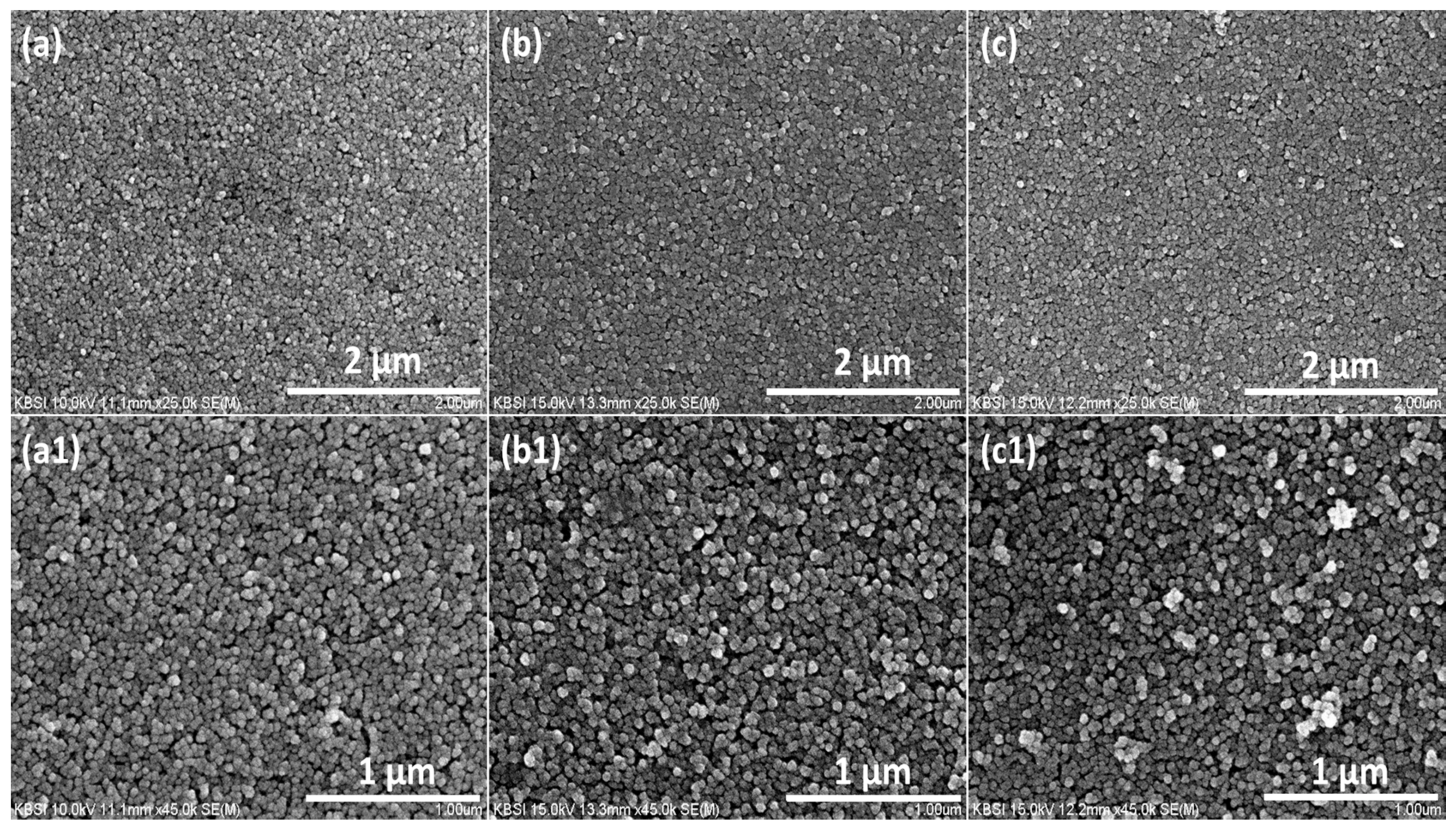
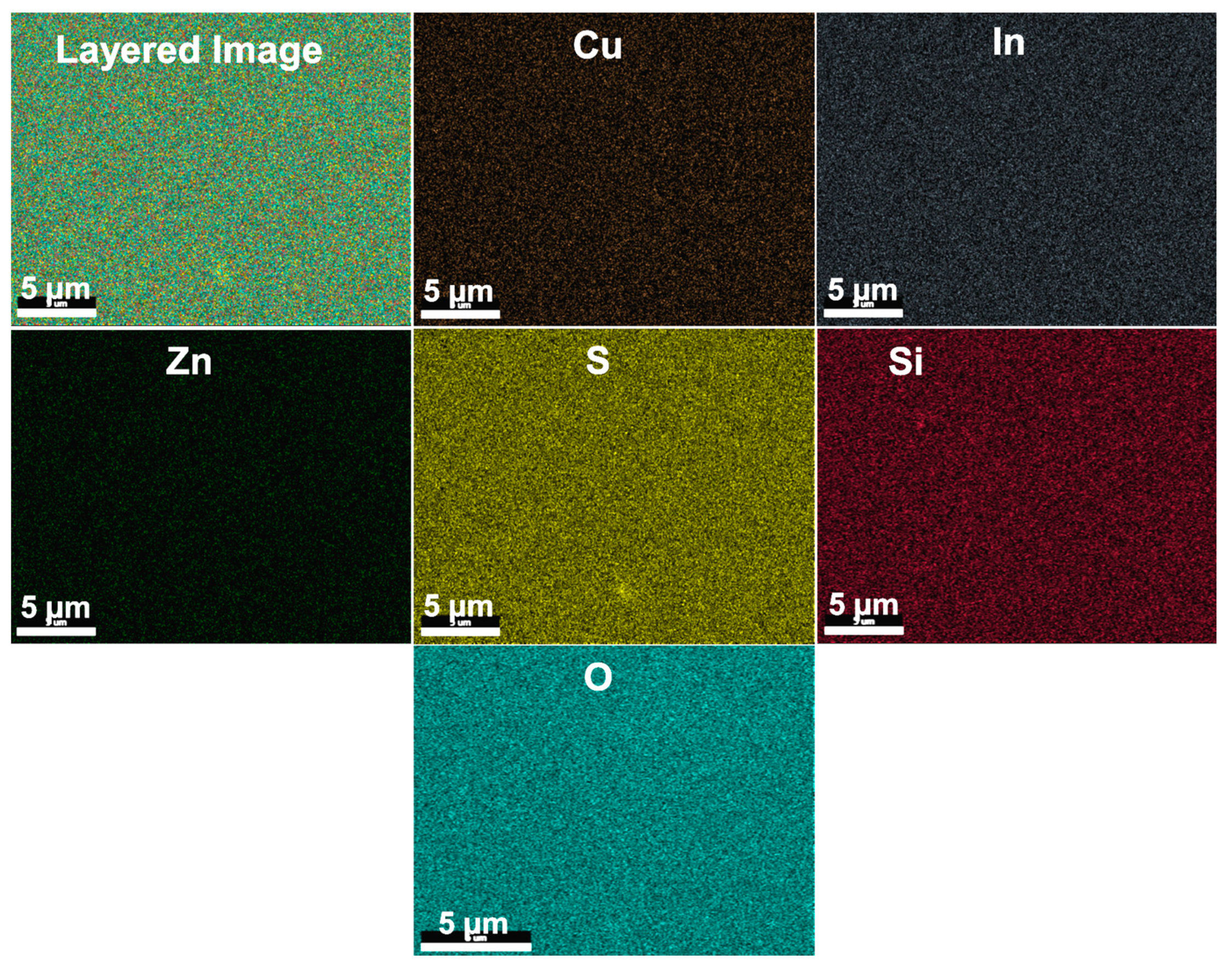
2.1. Morphological Characterization

Figure 1(a,a1,b,b1,c,c1) show the scanning electron microscopy (SEM) images of the CuInS2, CuInS2/ZnS, and CuInS2/ZnS/SiO2 layers on the surface of TiO2. The bare CuInS2 film in Figure 1a,a1 exhibit uniformly distributed nanoparticles on the TiO2 surface. All the samples exhibit the almost similar surface morphology and there is a slight increase in the particle size of with the deposition of ZnS and ZnS/SiO2 layers; however, the specific change in size of particles is difficult to examine and was inconclusive. Therefore, elemental mapping from SEM analysis and X-ray photoelectron spectroscopy (XPS) measurements were conducted to identify the ZnS and ZnS/SiO2 coatings on the surface of TiO2. Moreover, the compositional distributions of a TiO2/CuInS2/ZnS/SiO2 sample are further demonstrated by elemental mapping behavior, in which the homogeneous distribution and coexistence of Cu, In, Zn, S, Si and O elements are clearly observed in TiO2/CuInS2/ZnS/SiO2 sample (Figure 2). Such elemental mapping results unambiguously indicate that the CuInS2, ZnS and SiO2 were deposited successfully on the TiO2 surface.
The composition of the CuInS2/ZnS/SiO2 sample was investigated by XPS, as depicted in Figure 3. The XPS survey spectra in Figure 3a depict peaks for Ti2p, O1s, C1s, Cu2p, In3d, Zn2p, S2p, and Si2p, respectively. The binding energy of Cu 2p3/2 and Cu 2p1/2 were observed at 932.9 and 952.7 eV, respectively (Figure 3b), with no evident shake-up satellite signals in this Cu2p spectrum. The two major peaks of In are observed at 445.4 eV and 452.9 eV for In 3d5/2 and In 3d3/2, respectively (Figure 3c). Figure 3d depicts the binding energies for Zn 2p3/2 and Zn 2p1/2 of the prepared sample of CuInS2/ZnS/SiO2 at 1023.2 eV and 1046.2 eV respectively. The S 2p spectrum was yielded peaks of S 2p3/2 and S 2p1/2 at 162.0 eV and 163.0 eV binding energies, respectively (Figure 3e). In the Si 2p spectrum (Figure 3f), the main peak observed at 103.2 eV has been ascribed to Si in the oxidized form (SiO2) and the other shoulder peak can be assigned to the presence of crystalline Si (elemental Si).

2.2. Electrochemical Characterization

The J-V curves of the QDSSCs based on various photoanodes were obtained under AM 1.5 illumination (100 mW cm−2) are displayed in Figure 4 and the corresponding photovoltaic parameters are tabulated in Table 1. When only CuInS2 are deposited on TiO2 film, the QDSSC exhibits a JSC of 7.87 mA cm−2, VOC of 0.509 V, FF of 0.537, resulting a low PCE of 2.15%. However, when ZnS and ZnS/SiO2 passivation layers were deposited, all the photovoltaic parameters were greatly improved; the QDSSCs with a ZnS/SiO2 layer exhibit the good performance, with JSC, VOC, and FF reaching 12.83 mA cm−2, 0.603 V, and 0.598, respectively and the highest PCE of 4.63%, which is much higher than the PCE of 3.23% with a ZnS passivation layer. It is observed that the ZnO/SiO2 layer exhibiting higher performance than the bare and ZnS layers in QDSSCs, which is due to suppression of recombination losses in QDSSCs and increases the charge collection efficiency.
Electrochemical impedance spectroscopy (EIS) characterizations were conducted to identify the charge recombination processes in devices under forward bias (VOC) and dark condition. Figure 5 depicts the EIS spectra of various photoelectrodes and the Nyquist plots were fitted using Z-view software with the equivalent circuit provided in the inset of Figure 5. The corresponding fitting results are shown in Table 1. The Nyquist plot consists of two semicircles and the first semicircle represents the resistance (RCE) at the CE/electrolyte interface. The second semicircle denotes the charge transfer resistance (Rct) at the interface of the TiO2/QDs/electrolyte. At higher frequency, the intercept on the real axis corresponds to the series resistance (Rs) of FTO substrate and the resistance of FTO/TiO2 [21,22]. It is noticed that there are no apparent differences observed in the RS and RCE due to the same CE and electrolyte used in these experiments. However, there is a noticeable difference in Rct; the Rct value for the CuInS2/ZnS/SiO2 based QDSSCs is 55.02 Ω, while Rct value for the CuInS2/ZnS and CuInS2 based QDSSCs are only 30.65 Ω and 23.95 Ω, respectively. The charge recombination resistance at the TiO2/QDs/electrolyte interface is mainly observed by Rct. The higher Rct value represents the suppressed recombination of the electrons and holes, and enhances the electron transfer process at the interface of TiO2/QDs/electrolyte. Therefore, it is confirmed that the deposition of ZnS/SiO2 layer on the CuInS2 QDs favors the efficient electron transfer from CuinS2 to TiO2 photoanodes with suppression of the interfacial charge recombination processes, which is more effectively than that of the ZnS passivation layer.
Furthermore, Open circuit voltage decay (OCVD) measurements were carried out to study the charge recombination process in QDSSCs and the results. OCVD analysis of QDSSCs was performed during relaxation form an illuminated quasiequilibrium state to the darkness. Figure 6 depicts the OCVD plots of the QDSSCs based on CuInS2, CuInS2/ZnS and CuInS2/ZnS/SiO2 photoanodes. Apparently, the CuInS2/ZnS/SiO2 cell delivered considerably longer decay times than the CuInS2 and CuInS2/ZnS cells, indicating a suppression of charge recombination process. Moreover, the VOC decay and electron life time are directly related according to following equation [23]:
τ e = ( k B T e ) ( d V OC d t ) 1
where kB is the Boltzmann constant, T is the absolute temperature, and e is the electronic charge. It can be noticed that the τe of all the devices increases with decreasing VOC. Among the QDSSCs investigated, the CuInS2/ZnS/SiO2 delivers longer τe than the CuInS2/ZnS and CuInS2 devices, implying suppressed recombination and efficient electron transfer at the TiO2/QDs/electrolyte, which is consistent with EIS analysis. Therefore, the slower VOC decay and longer τe of the CuInS2/ZnS/SiO2 device efficiently suppressed the electron recombination from TiO2 and QDs to electrolyte and higher charge collection efficiency contribute to the increased photovoltaic performance.
Several paths for charge recombination occur at the TiO2/QDs/electrolyte interface, which suppress the performance of QDSSCs. The deposition of ZnS/SiO2 layer on the surface of TiO2/CuInS2 can effectively suppress the charge recombination process at the photoanode/electrolyte interface (Figure 7) and enhance the QDSSCs performance.

3. Materials and Methods

3.1. Preparation of TiO2 Electrodes

TiO2 paste (20 nm, Ti-Nanoxide HT/TP, Solaronix) was doctor bladed on fluorine-doped tin oxide (FTO, 1.3 × 1.6 cm2) substrate and heated at 450 °C for 30 min. The film thickness was about 7.5 µm with an active area of 0.25 cm2 [24].

3.2. Deposition of CuInS2 QDs on TiO2 Electrodes

CuInS2 QDs was deposited on the TiO2 substrate using the SILAR process. TiO2 electrodes were immersed into the three different solutions: one of 0.05 M of Cu(NO3)2 for 2 min, another of 0.05 M of In(NO3)3 for 2 min, and a final one of 0.1 M of Na2S for 5 min. Following each immersion, the samples were rinsed with deionized (DI) water for 1 min to remove the excess precursors. This procedure comprises one CuInS2 SILAR cycle and was repeated six times.

3.3. Deposition of ZnS, ZnS/SiO2 Passivation Layers on TiO2/CuInS2 Electrodes

The ZnS passivation layer was deposited on TiO2/CuInS2 electrodes by a SILAR process. Typically, TiO2/CuInS2 electrodes were successively immersed into aqueous solutions containing 0.1 M of Zn(NO3)2 and 0.1 M Na2S for 1 min, respectively. This process was repeated for three times and the electrode is named as CuInS2/ZnS. Furthermore, SiO2 coating was deposited by dipping the CuInS2/ZnS electrodes in ethanol solution containing 0.01 M tetraethylorthosilicate and 0.1 M NH4OH for 1 h. The as-fabricated electrode is termed as CuInS2/ZnS/SiO2.

3.4. QDSSC Fabrication

CuS CE on FTO substrate was fabricated according to the literature [25]. The photoanode and CuS CEs were combined using sealant (SX 1170-60, Solaronix) and the space between the electrodes was filled with polysulfide electrolyte (1 M Na2S, 2 M S, and 0.2 M KCl in methanol and water at a ratio of 7:3).

3.5. Characterizations

The morphology of the samples were evaluated by SEM (S-2400, Hitachi). XPS measurement was investigated using VG Scientific ESCALAB 250. The J-V measurements were examined under AM 1.5 sunglight (100 mW cm−2) using an ABET Technologies (USA) solar simulator. EIS was investigated using a BioLogic SP-150 work station under one sun illumination over the frequency of 100 mHz–500 kHz.

4. Conclusions

Introduction of ZnS/SiO2 passivation layer on TiO2/CuInS2 QDs has been demonstrated to be an effective and promising approach to significantly suppress the charge recombination at the interface of photoanode/electrolyte and enhance the power conversion efficiency. Interestingly, an overall η of 4.63% was obtained for the TiO2/CuInS2/ZnS/SiO2 device, which is 43% enhancement over the η = 3.23% for the TiO2/CuInS2/ZnS and more than 115% increment over the η = 2.15% for the TiO2/CuInS2 device. Overall, ZnS/SiO2 passivation layer is an effective approach to enhance the overall power conversion efficiency of QDSSCs.

Author Contributions

H.J.K. and J.H.B performed device performance measurements. H.S. and M.S. helped in the analysis of the data. C.V.V.M.G. designed this research idea and writing the manuscript.

Funding

This research was supported by Basic Science Research Program through the National Research Foundation of Korea (NRF) funded by the Ministry of Education, ICT and Future planning (NRF-2016K2A9A2A08003717).

Conflicts of Interest

The authors declare no conflict of interest.

References

  1. Lee, H.J.; Wang, M.; Chen, P.; Gamelin, D.R.; Zakeeruddin, S.M.; Grätzel, M.; Nazeeruddin, M.K. Efficient CdSe Quantum Dot-Sensitized Solar Cells Prepared by an Improved Successive Ionic Layer Adsorption and Reaction Process. Nano Lett. 2009, 9, 4221–4227. [Google Scholar] [CrossRef] [PubMed]
  2. Shen, X.; Jia, J.; Lin, Y.; Zhou, X. Enhanced performance of CdTe quantum dot sensitized solar cell via anion exchanges. J. Power Sources 2015, 277, 215–221. [Google Scholar] [CrossRef]
  3. Gopi, C.V.V.M.; Haritha, M.V.; Kim, S.K.; Kim, H.J. A strategy to improve the energy conversion efficiency and stability of quantum dot-sensitized solar cells using manganese-doped cadmium sulfide quantum dots. Dalton Trans. 2015, 44, 630–638. [Google Scholar] [CrossRef] [PubMed]
  4. González-Pedro, V.; Sima, C.; Marzari, G.; Boix, P.P.; Giménez, S.; Shen, Q.; Dittrich, T.; Seró, I.M. High performance PbS Quantum Dot Sensitized Solar Cells exceeding 4% efficiency: the role of metal precursors in the electron injection and charge separation. Phys. Chem. Chem. Phys. 2013, 15, 13835–13843. [Google Scholar] [CrossRef] [PubMed] [Green Version]
  5. Zhang, J.; Gao, J.; Church, C.P.; Miller, E.M.; Luther, J.M.; Klimov, V.I.; Beard, M.C. PbSe Quantum Dot Solar Cells with More than 6% Efficiency Fabricated in Ambient Atmosphere. Nano Lett. 2014, 14, 6010–6015. [Google Scholar] [CrossRef] [PubMed]
  6. Kamat, P.V. Quantum Dot Solar Cells. Semiconductor Nanocrystals as Light Harvesters. J. Phys. Chem. C 2008, 112, 18737–18753. [Google Scholar] [CrossRef]
  7. Kongkanand, A.; Tvrdy, K.; Takechi, K.; Kuno, M.; Kamat, P.V. Quantum Dot Solar Cells. Tuning Photoresponse through Size and Shape Control of CdSe−TiO2 Architecture. J. Am. Chem. Soc. 2008, 130, 4007–4015. [Google Scholar] [CrossRef] [PubMed]
  8. Booth, M.; Brown, A.P.; Evans, S.D.; Critchley, K. Determining the Concentration of CuInS2 Quantum Dots from the Size-Dependent Molar Extinction Coefficient. Chem. Mater. 2012, 24, 2064–2070. [Google Scholar] [CrossRef]
  9. Leach, A.D.P.; Macdonald, J.E. Optoelectronic Properties of CuInS2 Nanocrystals and Their Origin. J. Phys. Chem. Lett. 2016, 7, 572–583. [Google Scholar] [CrossRef] [PubMed]
  10. Li, T.L.; Lee, Y.L.; Teng, H. CuInS2 quantum dots coated with CdS as high-performance sensitizers for TiO2 electrodes in photoelectrochemical cells. J. Mater. Chem. 2011, 21, 5089–5098. [Google Scholar] [CrossRef]
  11. Bang, J.H.; Kamat, P.V. Quantum Dot Sensitized Solar Cells. A Tale of Two Semiconductor Nanocrystals: CdSe and CdTe. ACS Nano 2009, 3, 1467–1476. [Google Scholar] [CrossRef] [PubMed]
  12. Xu, X.; Wan, Q.; Luan, C.; Mei, F.; Zhao, Q.; An, P.; Liang, Z.; Xu, G.; Zapien, J.A. Fabrication of CuInS2-Sensitized Solar Cells via an Improved SILAR Process and Its Interface Electron Recombination. ACS Appl. Mater. Interfaces 2013, 5, 10605–10613. [Google Scholar] [CrossRef] [PubMed]
  13. Kontos, A.G.; Likodimos, V.; Vassalou, E.; Kapogianni, I.; Raptis, Y.S.; Raptis, C.; Falaras, P. Nanostructured titania films sensitized by quantum dot chalcogenides. Nanoscale Res. Lett. 2011, 6, 266–271. [Google Scholar] [CrossRef] [PubMed]
  14. Lee, H.J.; Bang, J.; Park, J.; Kim, S.; Park, S.M. Multilayered semiconductor (CdS/CdSe/ZnS)-sensitized TiO2 mesoporous solar cells: All prepared by successive ionic layer adsorption and reaction processes. Chem. Mater. 2010, 22, 5636–5643. [Google Scholar] [CrossRef]
  15. Chang, J.Y.; Su, L.F.; Li, C.H.; Chang, C.C.; Lin, J.M. Efficient “green” quantum dot-sensitized solar cells based on Cu2S–CuInS2–ZnSe architecture. Chem. Commun. 2012, 48, 4848–4850. [Google Scholar] [CrossRef] [PubMed]
  16. Zhou, Z.; Yuan, S.; Fan, J.; Hou, Z.; Zhou, W.; Du, Z.; Wu, S. CuInS2 quantum dot-sensitized TiO2 nanorod array photoelectrodes: Synthesis and performance optimization. Nanoscale Res. Lett. 2012, 7, 652–659. [Google Scholar] [CrossRef] [PubMed]
  17. Meng, W.; Zhou, X.; Qiu, Z.; Liu, C.; Chen, J.; Yue, W.; Wang, M.; Bi, H. Reduced graphene oxide-supported aggregates of CuInS2 quantum dots as an effective hybrid electron acceptor for polymer-based solar cells. Carbon 2016, 96, 532–540. [Google Scholar] [CrossRef]
  18. Han, M.; Jia, J.; Yu, L.; Yi, G. Fabrication and photoelectrochemical characteristics of CuInS2 and PbS quantum dot co-sensitized TiO2 nanorod photoelectrodes. RSC Adv. 2015, 5, 51493–51500. [Google Scholar] [CrossRef]
  19. Diguna, L.J.; Qing, S.; Kobayashi, J.; Toyoda, T. High efficiency of CdSe quantum-dot-sensitized TiO2 inverse opal solar cells. Appl. Phys. Lett. 2007, 91, 023116–023118. [Google Scholar] [CrossRef]
  20. De la Fuente, M.S.; Sánchez, R.S.; González-Pedro, V.; Boix, P.P.; Mhaisalkar, S.G.; Rincón, M.E.; Bisquert, J.; Mora-Seró, I. Effect of Organic and Inorganic Passivation in Quantum-Dot-Sensitized Solar Cells. J. Phys. Chem. Lett. 2013, 4, 1519–1525. [Google Scholar] [CrossRef] [PubMed] [Green Version]
  21. Gopi, C.V.V.M.; Haritha, M.V.; Kim, S.K.; Kim, H.J. Improved photovoltaic performance and stability of quantum dot sensitized solar cells using Mn–ZnSe shell structure with enhanced light absorption and recombination control. Nanoscale 2015, 7, 12552–12563. [Google Scholar] [CrossRef] [PubMed]
  22. Kim, H.J.; Kim, S.W.; Gopi, C.V.V.M.; Kim, S.K.; Rao, S.S.; Jeong, M.S. Improved performance of quantum dot-sensitized solar cells adopting a highly efficient cobalt sulfide/nickel sulfide composite thin film counter electrode. J. Power Sources 2014, 268, 163–170. [Google Scholar] [CrossRef]
  23. Liu, Z.; Miyauchi, M.; Uemura, Y.; Cui, Y.; Hara, K.; Zhao, Z.; Sunahara, K.; Furube, A. Enhancing the performance of quantum dots sensitized solar cell by SiO2 surface coating. Appl. Phys. Lett. 2010, 96. [Google Scholar] [CrossRef]
  24. Kim, H.J.; Kim, D.J.; Rao, S.S.; Savariraj, A.D.; Kyoung, K.S.; Son, M.K.; Gopi, C.V.V.M.; Prabakar, K. Highly efficient solution processed nanorice structured NiS counterelectrode for quantum dot sensitized solar cell. Electrochim. Acta 2014, 127, 427–432. [Google Scholar] [CrossRef]
  25. Kim, H.J.; Sik, L.M.; Gopi, C.V.V.M.; Haritha, M.V.; Rao, S.S.; Kim, S.K. Cost-effective and morphology controllable PVP based highly efficient CuS counter electrodes for high-efficiency quantum dot-sensitized solar cells. Dalton Trans. 2015, 44, 11340–11351. [Google Scholar] [CrossRef] [PubMed]
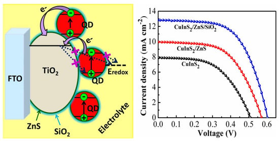
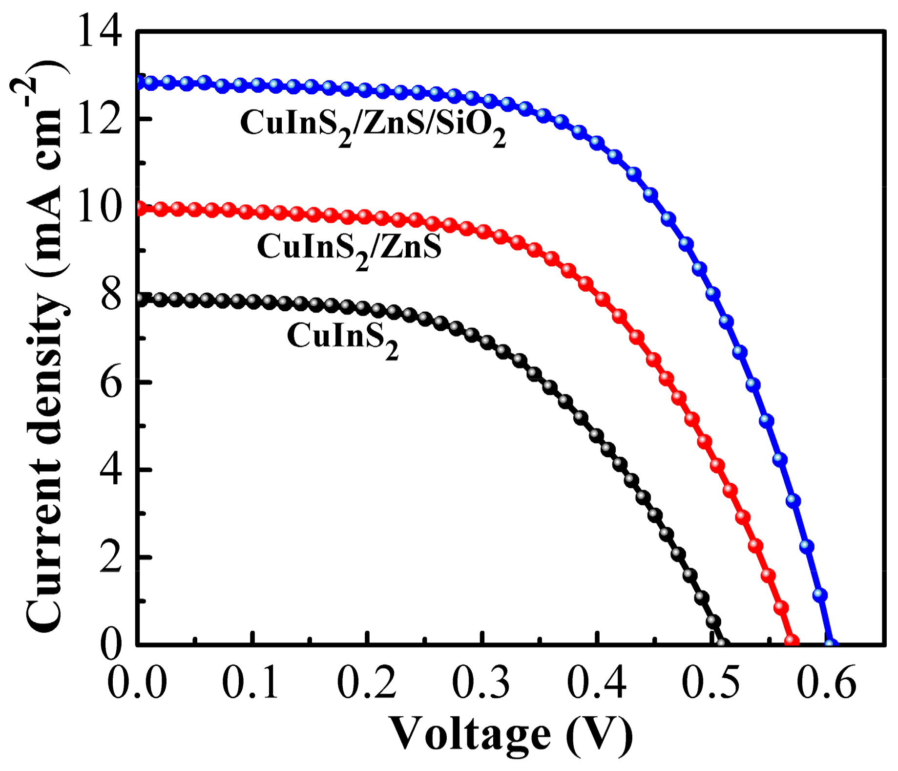
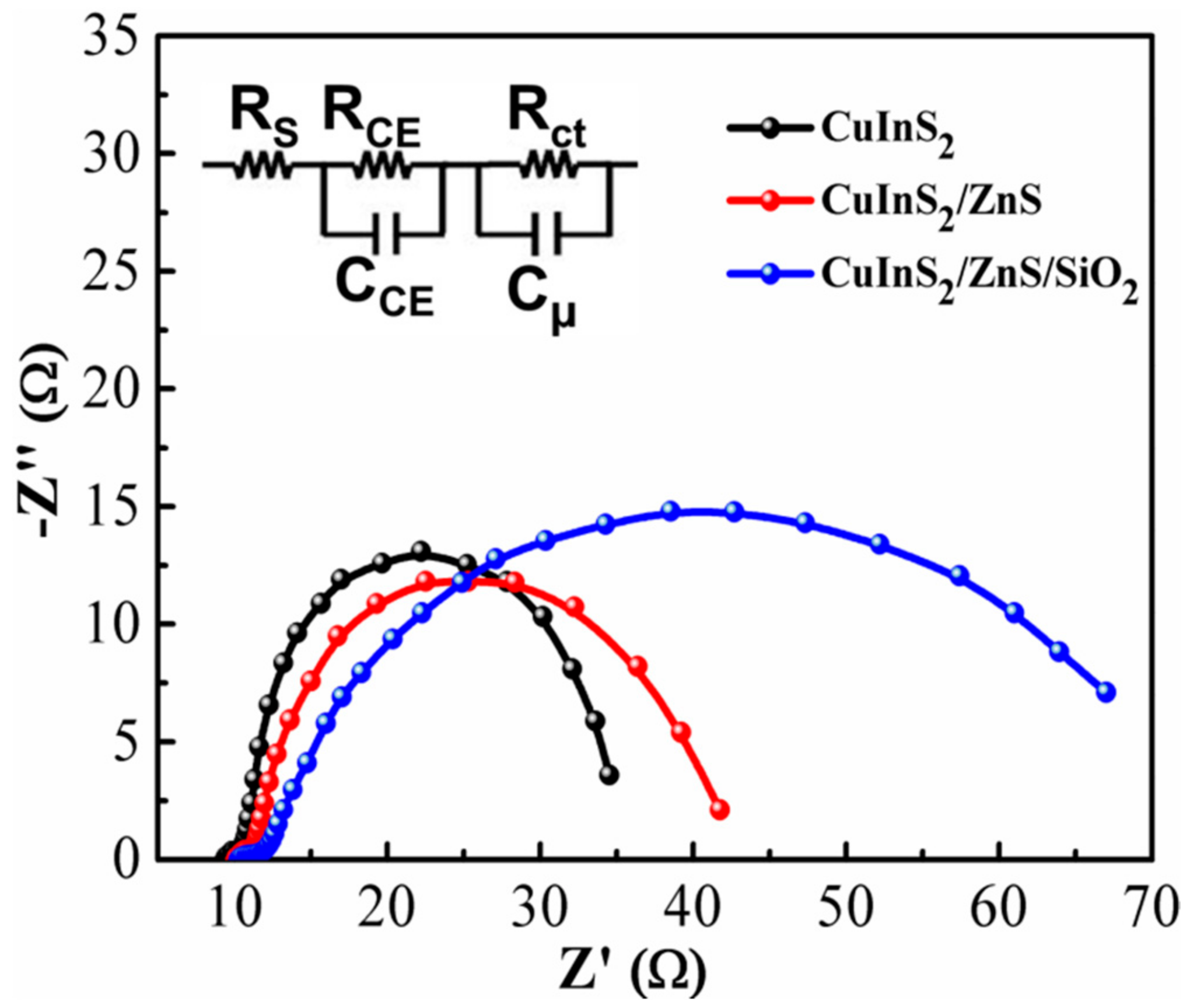
Figure 1. SEM images of the (a,a1) CuInS2, (b,b1) CuInS2/ZnS, and (c,c1) CuInS2/ZnS/SiO2 layers on the surface of TiO2.
Energies 11 01931 g001
Figure 2. Elemental mapping images of the Cu, In, Zn, S, Si and O for the TiO2/CuInS2/ZnS/SiO2 samples.
Energies 11 01931 g002
Figure 3. (a) XPS survey of TiO2/CuInS2/ZnS/SiO2 film. Core-level XPS spectrum of (b) Cu 2p, (c) In 3d, (d) Zn 2p, (e) S 2p, and (d) Si 2p elements.
Energies 11 01931 g003
Figure 4. Current density−voltage (J−V) curves of CuInS2, CuInS2/ZnS and CuInS2/ZnS/SiO2 based QDSSCs.
Energies 11 01931 g004
Figure 5. EIS curves of QDSSCs based CuInS2 and CuInS2/ZnS and CuInS2/ZnS/SiO2 cells in the form of Nyquist-plots and the inset shows the equivalent circuit used to fit the impedance spectra.
Energies 11 01931 g005
Figure 6. OCVD curves of QDSSCs based CuInS2 and CuInS2/ZnS and CuInS2/ZnS/SiO2 cells.
Energies 11 01931 g006
Figure 7. Possible charge transfer behavior in the TiO2/CuInS2/ZnS/SiO2 QDSSCs.
Energies 11 01931 g007
Table 1. Photovoltaic properties and EIS results of QDSSCs fabricated various sensitized conditions.
CellVoc (V)Jsc (mA cm−2)FFη%RS (Ω)RCE (Ω)Rct (Ω)
CuInS20.5097.870.5372.159.340.8430.65
CuInS2/ZnS0.5699.950.5713.2310.031.0323.95
CuInS2/ZnS/SiO20.60312.830.5984.6310.241.1655.02

