Enhancing the Robustness of the Wireless Power Transfer System to Uncertain Parameter Variations Using an Interval-Based Uncertain Optimization Method

Abstract
:1. Introduction
2. Modeling and Analysis of the WPT System with Uncertainty
2.1. Uncertain Parameters in the WPT System
2.2. Modeling of the WPT System
2.2.1. Transmitter Coil and Receiver Coil
2.2.2. Tuning and Impedance Matching Circuits
2.2.3. Overall WPT System
2.3. Analysis of the Uncertain Parameters
3. Interval-Based Uncertain Optimization Method for the WPT System
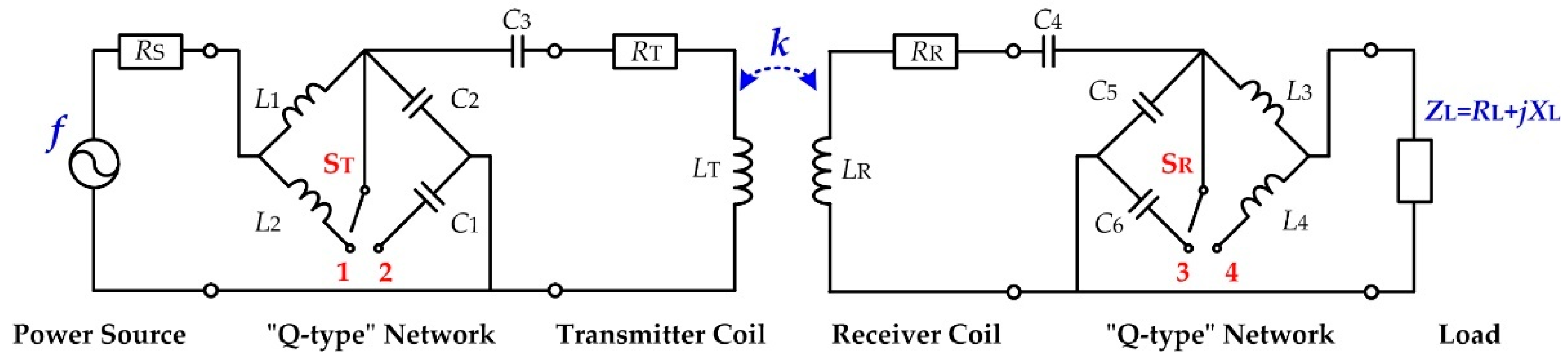
3.1. A Modified WPT System Structure
3.2. Interval-Based Uncertain Optimization Model
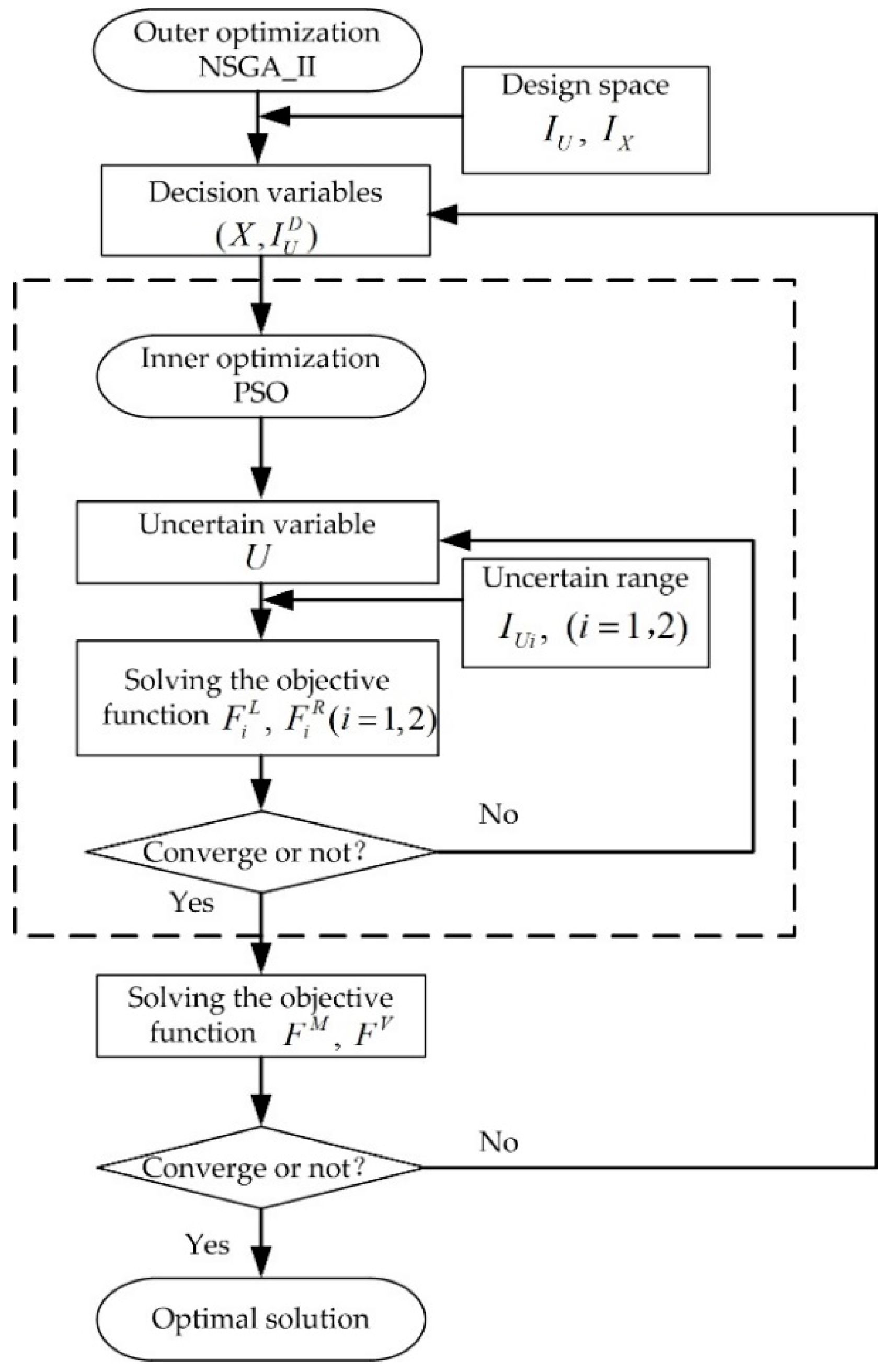
3.3. Bi-Level Nested Optimization Algorithm
3.4. Optimization Results
3.4.1. Pareto Fronts
3.4.2. Tradeoff Solutions
4. Experimental Verifications
4.1. Hardware Implementations
4.1.1. Modified WPT System
4.1.2. SS Compensated WPT System
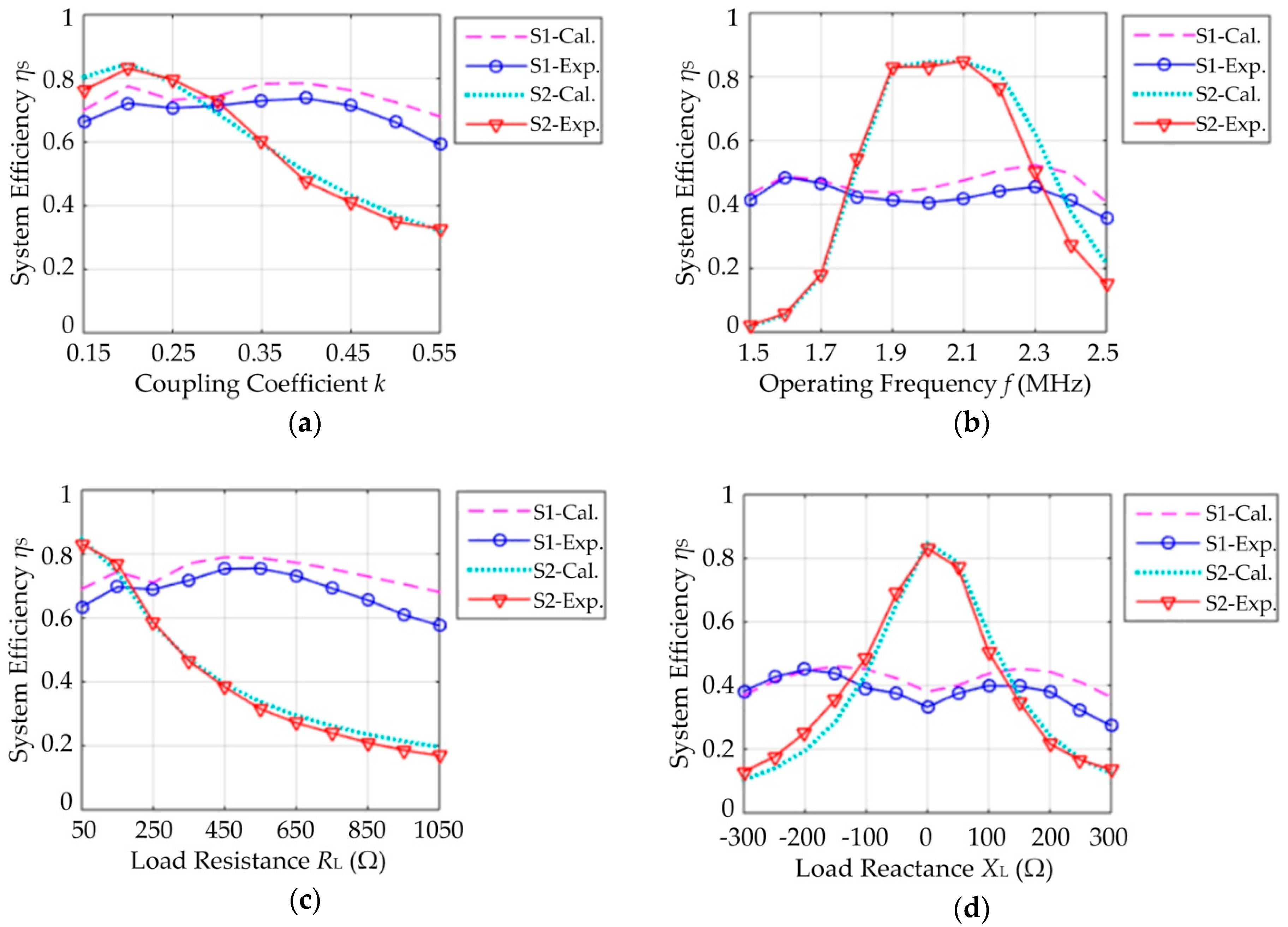
4.2. Experimental Results
5. Conclusions
- A modified WPT system structure is proposed in this paper. Two Q-type impedance matching networks are inserted in the transmitter circuit and the receiver circuit, respectively. By doing so, the modified WPT system can operate at two different modes. To address uncertain parameter variations, the modified WPT system can switch from one operating mode to the other mode, which is efficient and easy to implement.
- An interval-based uncertain optimization method is proposed to enhance the robustness of the modified WPT system. A double-objective uncertain optimization model for the modified WPT system is built, and a bi-level nested optimization algorithm is proposed to find robust solutions. Through this method, the modified WPT system can achieve good robustness performance when the coupling coefficient, the operating frequency, the load resistance or the load reactance varies over a wide range.
- Compared with active control methods, the proposed method in this paper only uses passive compensation networks (Q-type impedance matching networks). Therefore, the structure and control difficulty of the WPT system can be reduced. The size of the Q-type networks can be made small, which contributes to the miniaturization of the overall system. The proposed method is more suitable for some applications where high robustness performance, medium system efficiency, and a small system size are required.
Author Contributions
Funding
Conflicts of Interest
References
- Hwang, I.; Jang, Y.J.; Ko, Y.D.; Lee, M.S. System optimization for dynamic wireless charging electric vehicles operating in a multiple-route environment. IEEE Trans. Intell. Transp. Syst. 2017, 99, 1–18. [Google Scholar] [CrossRef]
- Assawaworrarit, S.; Yu, X.; Fan, S. Robust wireless power transfer using a nonlinear parity-time-symmetric circuit. Nature 2017, 546, 387–390. [Google Scholar] [CrossRef] [PubMed]
- Patil, D.; Mcdonough, M.; Miller, J.; Fahimi, B.; Balsara, P.T. Wireless power transfer for vehicular applications: Overview and challenges. IEEE Trans. Transp. Electrification 2018, 4, 3–37. [Google Scholar] [CrossRef]
- Diekhans, T.; De Doncker, R.W. A dual-side controlled inductive power transfer system optimized for large coupling factor variations and partial load. IEEE Trans. Power Electron. 2015, 30, 6320–6328. [Google Scholar] [CrossRef]
- Hwang, K.; Cho, J.; Kim, D.; Park, J.; Kwon, J.H.; Kwak, S.I.; Park, H.H.; Ahn, S. An autonomous coil alignment system for the dynamic wireless charging of electric vehicles to minimize lateral misalignment. Energies 2017, 10, 315. [Google Scholar] [CrossRef]
- Orekan, T.; Zhang, P.; Shih, C. Analysis, design, and maximum power-efficiency tracking for undersea wireless power transfer. IEEE J. Emerg. Sel. Top. Power Electron. 2018, 6, 843–854. [Google Scholar] [CrossRef]
- Huang, S.; Li, Z.; Lu, K. Transfer efficiency analysis of wireless power transfer system under frequency drift. J. Appl. Phys. 2015, 117, 17E706. [Google Scholar] [CrossRef]
- Chabalko, M.; Besnoff, J.; Laifenfeld, M.; Ricketts, D.S. Resonantly coupled wireless power transfer for non-stationary loads with application in automotive environments. IEEE Trans. Ind. Electron. 2017, 64, 91–103. [Google Scholar] [CrossRef]
- Fu, M.; Yin, H.; Zhu, X.; Ma, C. Analysis and tracking of optimal load in wireless power transfer systems. IEEE Trans. Power Electron. 2015, 30, 3952–3963. [Google Scholar] [CrossRef]
- Mercier, P.P.; Chandrakasan, A.P. Rapid wireless capacitor charging using a multi-tapped inductively coupled secondary coil. IEEE Trans. Circuits Syst. 2013, 60, 2263–2272. [Google Scholar] [CrossRef]
- Xiao, C.; Liu, Y.; Cheng, D.; Wei, K. New insight of maximum transferred power by matching capacitance of a wireless power transfer system. Energies 2017, 10, 688. [Google Scholar] [CrossRef]
- Heebl, J.D.; Thomas, E.M.; Penno, R.P.; Grbic, A. Comprehensive analysis and measurement of frequency-tuned and impedance-tuned wireless non-radiative power-transfer systems. IEEE Antennas Propag. Mag. 2014, 56, 44–60. [Google Scholar] [CrossRef]
- Kim, N.Y.; Kim, K.Y.; Choi, J.; Kim, C.W. Adaptive frequency with power-level tracking system for efficient magnetic resonance wireless power transfer. Electron. Lett. 2012, 48, 452–454. [Google Scholar] [CrossRef]
- Huang, S.; Li, Z.; Lu, K. Frequency splitting suppression method for four-coil wireless power transfer system. IET Power Electron. 2016, 9, 2859–2864. [Google Scholar] [CrossRef]
- Beh, T.C.; Kato, M.; Imura, T.; Oh, S.; Hori, Y. Automated impedance matching system for robust wireless power transfer via magnetic resonance coupling. IEEE Trans. Ind. Electron. 2013, 60, 3689–3698. [Google Scholar] [CrossRef]
- Luo, Y.; Yang, Y.; Chen, Z. Self-tuning wireless power transmission scheme based on on-line scattering parameters measurement and two-side power matching. Sci. Rep. 2014, 4, 4332. [Google Scholar] [CrossRef] [PubMed]
- Zou, Y.; Dai, X.; Li, W.; Sun, Y. Robust design optimisation for inductive power transfer systems from topology collection based on an evolutionary multi-objective algorithm. IET Power Electron. 2015, 8, 1767–1776. [Google Scholar] [CrossRef]
- Ahn, D.; Kim, S.; Moon, J.; Cho, I.K. Wireless power transfer with automatic feedback control of load resistance transformation. IEEE Trans. Power Electron. 2016, 31, 7876–7886. [Google Scholar] [CrossRef]
- Li, Y.; Duan, Q.; Zou, Y. High robustness control for robotic wireless power transfer systems with multiple uncertain parameters using a virtual buck converter. Energies 2017, 10, 517. [Google Scholar] [CrossRef]
- Rentschler, M.; Bhattacharya, I. Decoupled control of wireless power transfer: Eliminating the interdependence of load resistance and coupling to achieve a simple control framework with fast response times. Int. J. Electr. Power Energy Syst. 2018, 99, 156–163. [Google Scholar] [CrossRef]
- Su, Y.G.; Zhang, H.Y.; Wang, Z.H.; Hu, A.P.; Chen, L.; Sun, Y. Steady-state load identification method of inductive power transfer system based on switching capacitors. IEEE Trans. Power Electron. 2015, 30, 6349–6355. [Google Scholar] [CrossRef]
- Dai, X.; Li, X.; Li, Y.; Deng, P.; Tang, C. A maximum power transfer tracking method for WPT systems with coupling coefficient identification considering two-value problem. Energies 2017, 10, 1665. [Google Scholar] [CrossRef]
- Dai, X.; Li, X.; Li, Y.; Hu, A.P. Maximum efficiency tracking for wireless power transfer systems with dynamic coupling coefficient estimation. IEEE Trans. Power Electron. 2018, 33, 5005–5015. [Google Scholar] [CrossRef]
- Lim, Y.; Tang, H.; Lim, S.; Park, J. An adaptive impedance-matching network based on a novel capacitor matrix for wireless power transfer. IEEE Trans. Power Electron. 2014, 29, 4403–4413. [Google Scholar] [CrossRef]
- Li, S.; Li, W.; Deng, J.; Nguyen, T.D.; Mi, C.C. A double-sided LCC compensation network and its tuning method for wireless power transfer. IEEE Trans. Veh. Technol. 2015, 64, 2261–2273. [Google Scholar] [CrossRef]
- Hui, S.Y.R.; Zhong, W.; Lee, C.K. A critical review of recent progress in mid-range wireless power transfer. IEEE Trans. Power Electron. 2014, 29, 4500–4511. [Google Scholar] [CrossRef]
- Luo, Y.; Yang, Y.; Chen, S.; Wen, X. A frequency-tracking and impedance-matching combined system for robust wireless power transfer. Int. J. Antenn. Propag. 2017, 2017, 1–13. [Google Scholar] [CrossRef]
- Ye, W.; Chen, L.; Liu, F.; Chen, X.; Wang, X. Analysis and optimization of 3-coil magnetically coupled resonant wireless power transfer system for stable power transmission. In Proceedings of the IEEE Energy Conversion Congress and Exposition (ECCE), Cincinnati, OH, USA, 1–5 October 2017; pp. 2584–2589. [Google Scholar]
- Feng, H.; Cai, T.; Duan, S.; Zhang, X.; Hu, H.; Niu, J. A Dual-side-detuned series–series compensated resonant converter for wide charging region in a wireless power transfer system. IEEE Trans. Ind. Electron. 2018, 65, 2177–2188. [Google Scholar] [CrossRef]
- Zhang, W.; Wong, S.C.; Chi, K.T.; Chen, Q. Design for efficiency optimization and voltage controllability of series–series compensated inductive power transfer systems. IEEE Trans. Power Electron. 2014, 29, 191–200. [Google Scholar] [CrossRef]
- Yang, Y.; Zhong, W.; Kiratipongvoot, S.; Tan, S.C.; Hui, S.Y.R. Dynamic improvement of series–series compensated wireless power transfer systems using discrete sliding mode control. IEEE Trans. Power Electron. 2018, 33, 6351–6360. [Google Scholar] [CrossRef]
- Liu, S.; Liu, M.; Yang, S.; Ma, C.; Zhu, X. A novel design methodology for high-efficiency current-mode and voltage-mode class-E power amplifiers in wireless power transfer systems. IEEE Trans. Power Electron. 2017, 32, 4514–4523. [Google Scholar] [CrossRef]
- Shi, Y. Particle swarm optimization: Developments, applications and resources. In evolutionary computation. In Proceedings of the 2001 Congress on Evolutionary Computation, Seoul, Korea, 27–30 May 2001; pp. 81–86. [Google Scholar]
- Deb, K.; Pratap, A.; Agarwal, S.; Meyarivan, T.A.M.T. A fast and elitist multiobjective genetic algorithm: NSGA-II. IEEE Trans. Evol. Comput. 2002, 6, 182–197. [Google Scholar] [CrossRef] [Green Version]
- Pereyra, V.; Saunders, M.; Castillo, J. Equispaced Pareto front construction for constrained bi-objective optimization. Math. Comput. Model. 2013, 57, 2122–2131. [Google Scholar] [CrossRef]
- Cai, Z.; Wang, Y. A multiobjective optimization-based evolutionary algorithm for constrained optimization. IEEE Trans. Evol. Comput. 2006, 10, 658–675. [Google Scholar] [CrossRef]


| Type | Topology | Transmission Parameters |
|---|---|---|
| Series |  | |
| Parallel | 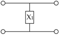 | |
| Combination | 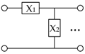 |
| Certain Parameter | Value |
|---|---|
| Source resistance | 50 Ω |
| Coil resistances | 1 Ω |
| Coil inductances | 30 μH |
| Series Capacitors | 211 pF |
| Uncertain Parameter | Variation Range |
| Coupling coefficient | |
| Operating frequency | |
| Load resistance | |
| Load reactance |
| Switch States | Transmission Parameters of the Q-type Network at Transmitter-Side | Transmission Parameters of the Q-type Network at Receiver-Side |
|---|---|---|
| Mode 1: | ||
| Mode 2: |
| Certain Parameter | Value |
|---|---|
| Source resistance | |
| Coil resistances | |
| Coil inductances | |
| Uncertain Parameter | Variation Interval |
| Coupling coefficient | |
| Operating frequency | |
| Load resistance | |
| Load reactance |
| Item | Uncertain Variables | ||||
|---|---|---|---|---|---|
| Varies in [0.15, 0.55] | Varies in [1.5, 2.5] MHz | Varies in [50, 1050] Ω | Varies in [−300, 300] Ω | ||
| Tradeoff solutions | 0.25 | 1.8 | 250 | 0 | |
| 23.4 | 5.9 | 5.6 | 7.3 | ||
| 500.0 | 87.5 | 177.4 | 481.5 | ||
| 16.5 | 5.0 | 17.5 | 31.8 | ||
| 473.3 | 245.4 | 98.0 | 435.1 | ||
| 50.1 | 173.6 | 52.8 | 508.1 | ||
| 576.7 | 770.2 | 740.0 | 130.1 | ||
| 936.2 | 367.7 | 422.2 | 219.6 | ||
| 1079.8 | 442.6 | 471.1 | 666.4 | ||
| 491.7 | 988.7 | 850.0 | 625.5 | ||
| 230.4 | 60.4 | 285.6 | 70.3 | ||
| Objective functions | 0.735 | 0.463 | 0.727 | 0.412 | |
| 0.002 | 0.002 | 0.002 | 0.002 | ||
© 2018 by the authors. Licensee MDPI, Basel, Switzerland. This article is an open access article distributed under the terms and conditions of the Creative Commons Attribution (CC BY) license (http://creativecommons.org/licenses/by/4.0/).
Share and Cite
Luo, Y.; Yang, Y.; Wen, X.; Cheng, M. Enhancing the Robustness of the Wireless Power Transfer System to Uncertain Parameter Variations Using an Interval-Based Uncertain Optimization Method. Energies 2018, 11, 2032. https://doi.org/10.3390/en11082032
Luo Y, Yang Y, Wen X, Cheng M. Enhancing the Robustness of the Wireless Power Transfer System to Uncertain Parameter Variations Using an Interval-Based Uncertain Optimization Method. Energies. 2018; 11(8):2032. https://doi.org/10.3390/en11082032
Chicago/Turabian StyleLuo, Yanting, Yongmin Yang, Xisen Wen, and Ming Cheng. 2018. "Enhancing the Robustness of the Wireless Power Transfer System to Uncertain Parameter Variations Using an Interval-Based Uncertain Optimization Method" Energies 11, no. 8: 2032. https://doi.org/10.3390/en11082032