Improvement of the Response Speed for Switched Reluctance Generation System Based on Modified PT Control


1
Jiangsu Province Laboratory of Mining Electric and Automation, China University of Mining and Technology, Xuzhou 221116, China
2
Department of Electrical engineering & Electronic, University of Liverpool, Liverpool L69 3BX, UK
*
Author to whom correspondence should be addressed.
Energies 2018, 11(8), 2049; https://doi.org/10.3390/en11082049
Submission received: 1 July 2018
/
Revised: 19 July 2018
/
Accepted: 19 July 2018
/
Published: 7 August 2018
(This article belongs to the Special Issue Control and Nonlinear Dynamics on Energy Conversion Systems)
Abstract
:The Switched Reluctance Generator (SRG) is suitable for wind power generation due to its good reliability and robustness. However, The SRG system adopting the conventional control algorithm with Pulse Width Modulation (PWM) method has a drawback, low response speed. The pulse train (PT) control has been widely used in dc/dc power converters operating in the discontinuous conduction mode due to its advantages of simple implementation and fast response. In this paper, for the first time, the PT control method is modified and adopted for controlling the output voltage of SRG system in order to achieve fast response. The capacitor current on the output side is sampled and combined with the output voltage to select the pulse trains and the low frequency oscillation cased by PT can be suppressed by tuning the feedback coefficient of the capacitor current. Also, good performance can be guaranteed with a wide range of voltage regulations, fast response, and no overshoot. The experimental platform of an 8/6 SRG system is built, and the experimental results show that the PT control can be used for SRG system with good practicability.
1. Introduction
With the rapid development of the economy energy shortages have become an inevitable problem. As a clean and abundant energy source, wind energy has been widely used. Wind power has the good features of wide distribution, large reserves, cleanness, security, etc. Therefore, wind power generation has attracted general attention from countries all over the world. Following this trend, there is a rapid development in wind power generation technologies and the wind power industry [1,2,3].
Switched reluctance generators (SRG) have advantages such as simple structure, high fault-tolerant ability, high operating efficiency, and hard mechanical properties, which make them widely used in aerospace, mining, textile, papermaking, and other industries [4,5,6]. The rotor of the SRG has no winding, no brush, and no permanent magnet so that the manufacturing cost is low and no copper loss is encountered. Since the SRG power generation system can be operated synchronously with a wind turbine, it is not restricted by stability issues when the frequency is low. Therefore, even if the wind speed is low, it can also ensure that the system runs with a high efficiency of power generation through reasonable design and control. At the same time, the application of current direct drives has become the developing trend of wind power generation systems, the advantages of SRG are attracting more and more attention than those of other generators. In particular, the magnetic and electric circuits are independent of each other, and hence when a fault occurs in a phase, the system can still function by isolating the faulty phase. Therefore, it has high operational reliability and fault tolerance [7].
The traditional PID control strategy is the classical method of power generation control for switched reluctance generators (SRGs) [8]. However, under PID control, the output overshoot of SRG could be large under the speed regulation, and the transient response could be quite slow due to the error compensation network [9]. In addition, PID controller parameters are normally preset and fixed, so the control performance will deteriorate when the working conditions are changed. It has been pointed out that the Fuzzy control strategy is suitable for SRG systems [10]. The fuzzy control theory refers to a bionic controller based on fuzzy knowledge and rule inference [11]. According to certain rules of inference, it can achieve the control goal in a simple way [12]. However, the independent use of a fuzzy controller may lead to an unavoidable overshoot and larger steady-state error. The sliding-mode variable structure control could also be a competitor for the control of SRGs. As compared with other control strategies, sliding-mode variable structure control has the invariance of perturbation and external disturbances to the system, making it more widely used in cases with high requirements of reliability and robustness [13]. However, the phenomenon of inherent buffeting and the inevitable steady-state error result in poor steady-state performance.
The large fluctuation of electricity loads and the regular capacitor charging and discharging processes lead to high difficulty of control for the irregular excitation current. In addition, an output voltage fluctuation can occur, and the original characteristics of power generation are affected. Besides, more harmonic contents could be injected into the grid by the grid-connected inverter. Until now, there has been some research progress of reducing the output voltage ripple and enhancing the voltage stability of SRG power systems. Aiming at reducing the output voltage ripple of SRG, a capacitor filter, as designed in a previous paper [14], is used to effectively reduce the voltage harmonics, but the parameters of the filter are difficult to determine. The switched reluctance generation system can achieve better control of the output voltage by introducing the double-closed-loop PID control with variable parameters [15]. However, the controller only considers the output voltage and phase current as the control targets, and hence ignores the impacts of other states of the system, which compromises the dynamic performance of SRG [16]. In a previous paper [17], a sliding mode controller of variable structure based on a genetic algorithm was designed to eliminate the voltage ripple caused by factors such as speed and load which change during the operation. However, the introduced genetic algorithm optimization module makes the system complicated.
Recently, pulse train (PT) control has been proposed for switching dc–dc converters [18,19] operated in the discontinuous conduction mode (DCM). The PT control method can adjust the system output voltage by using two or more sets of combination of control pulses. Without the requirement of an error amplifier and corresponding compensation network, the PT controller has excellent control performance of a fast response and simple circuit structure [20,21,22]. PT control methods are also attempted to be used in converters operated under the continuous conduction mode (CCM). In a previous paper [23], a buck converter operated in CCM is carried out with PT control for the first time, the research results point out that when the equivalent series resistance (ESR) of output capacitance is small, the circuit gives the phenomenon of low frequency oscillation. Though increasing the output capacitance ESR can suppress the low frequency oscillation of the converter, the ripple of output voltage is increased. To broaden the application scope of PT control, a peak capacitance current pulse train (PCC-PT) control method is described [24]. For the application of PCC-PT in converters, both excellent steady-state and transient response characteristics are revealed.
As a new contribution, a modified CC-PT control method is put forward based on the analysis of the conventional pulse train (PT) control, which is then applied in an SRG power generator system for the first time. The proposed CC-PT controlled method could adjust the output voltage by combining two or more groups of preset control pulses without the need of the error compensation network, which has the advantage of quick response compared with the PWM method.
2. SRG Power Generation System
2.1. Principle of SRG
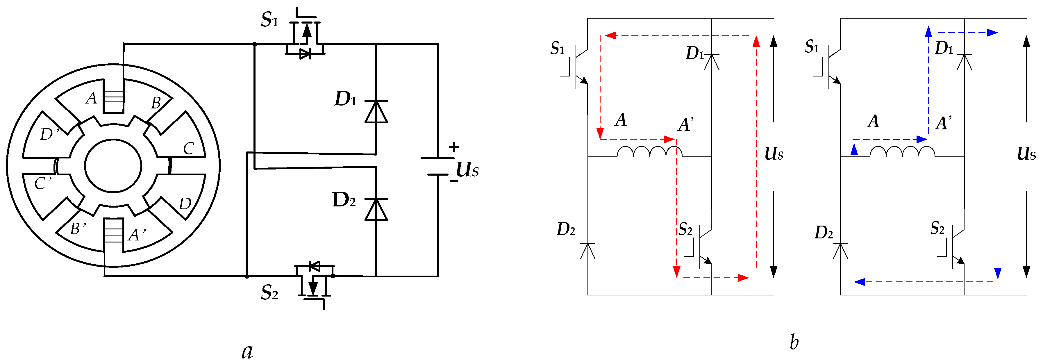
The SRG is a doubly salient varied reluctant motor, and the salient poles of stators and rotors are superposed by the common silicon steel sheet [25]. Figure 1a shows the structure of a SRG, of which phase A is taken as an example to illustrate the principle of its power generation. The SRG rotates clockwise to the position as shown in Figure 1a under the external force (wind power), and the switches S1, S2 are closed, then excite phase A and form the circuit S1→A→A’→S2. Figure 1b shows the excitation and freewheeling phases: First, the winding of phase A absorbs electrical energy from the source. Then, S1 and S2 are switched off and the winding of phase A is subjected to freewheeling through the freewheeling diodes, thus feeding back the energy stored by the winding to the DC power supply.
Because both the excitation and armature windings of the SRG are stator windings, the process of excitation and power generation must be controlled periodically. Its excitation process is controllable, while the generation process is not controllable, so the power generation is commonly controlled by adjusting the excitation current.
2.2. Control Methods of SRG
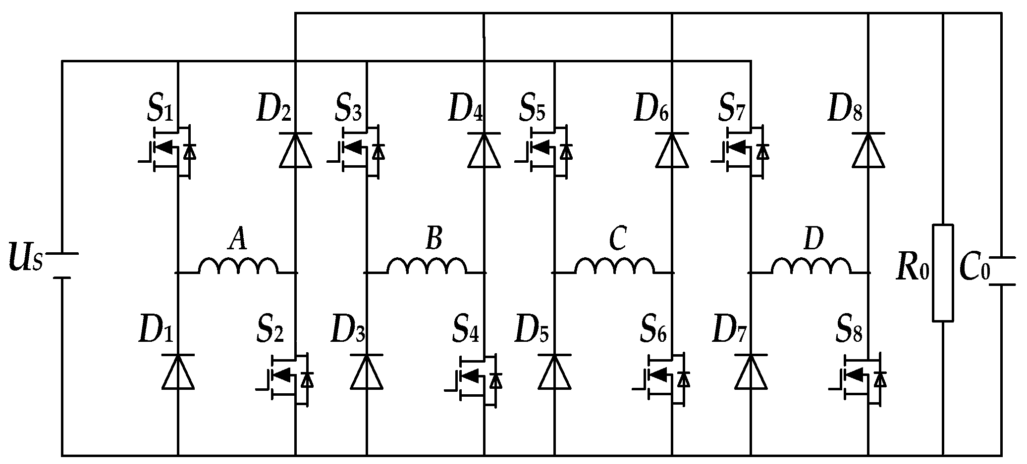
A SRG power generation system has two main excitation modes, which includes self-excitation and separate excitation. This paper chooses the separate excitation mode shown in Figure 2, which can separate the power generated by the winding from the excitation power completely and ensure high stability [26].
The control methods have been proposed for regulating the output power of SRG, such as angle position control (APC), current chopping control (CCC), and pulse width modulation (PWM).
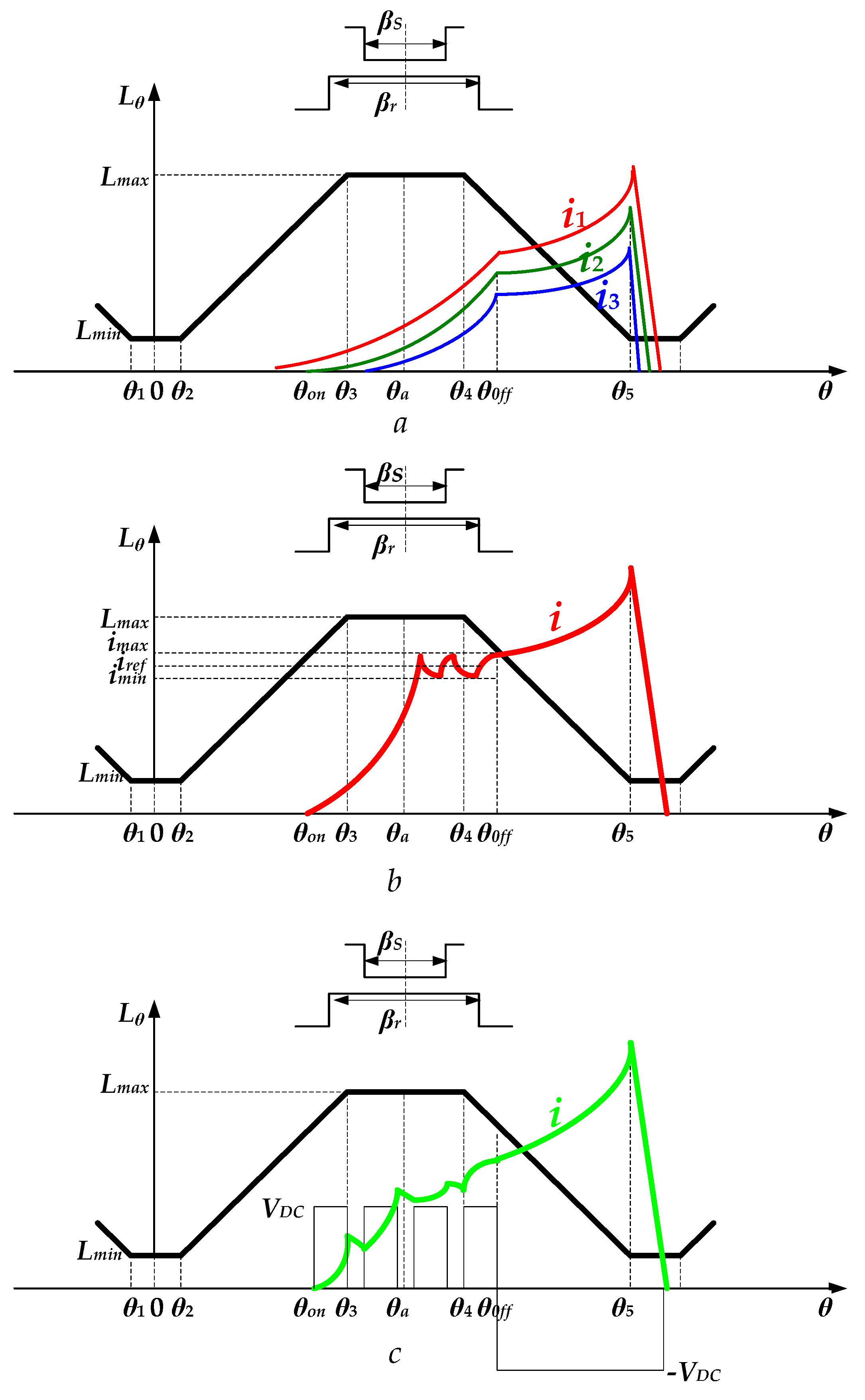
The APC control mode regulates the current waveforms by changing the turn-on angle (θon) and turn off angle (θoff). The output current can be changed by tuning the turn-on angle (θon) and turn off angle (θoff), as shown in Figure 3a. It can be seen that, higher conduction angles could lead to a larger output current. APC control can also be divided into the modes of changing θon, θoff and both θon and θoff together [27].
CCC is a method that directly chops the phase currents during the specific position of each phase. In CCC, the current i is compared with the chopper current (ichop). When the rotor position angle is between θon and θoff, where θon < θ < θoff, if I ≤ ichop, the switches are turned on, then the current i rises and gradually reaches the chopper; or else, the switches are turned off and the current i declines, as shown in Figure 3b. As compared with the APC control, where the current is not controllable, CCC directly controls the phase current and can get more accurate control performance [28].
The PWM control applies the PWM modulation signals on the main switches and adjusts the excitation voltage by changing the duty cycle to realize the control of excitation current. The PWM control of SRG can also be divided into two methods: one uses the PWM cut double tubes, and the other uses the PWM cut single tube. These two methods adjust the size of the excitation current and ultimately realize the control of output voltage. The waveforms of phase current by using PWM control is shown in Figure 3.
2.3. Analysis of Output Voltage Ripple of SRG
At the stage of building up the voltage field in the self-excited mode of SRG, the excited voltage source US provides an initial excitation voltage to the system. The self-excited mode generator system has heavy weight and high efficiency. However, when the loads fluctuate seriously and the capacitor charges or discharges, control difficulty of the irregular excitation current is encountered. The irregular excitation will finally result in the output voltage ripple, having an impact on the power generation performance and causing certain damage to the SRG’s body that shortens the lifetime of SRG.
The voltage balancing equation of the kth phase winding is given by
The phase inductance Lk(ik, θ) is a function of the phase current ik and the rotor position angle θ. Therefore, (1) can be converted to;
where Uk is kth phase output voltage, Lk is the phase inductance, ω is the generator angular speed, Rk is the resistance of the phase winding, and ik is the phase current.
In the nonlinear model, the voltage at generator windings in excitation and power generation are given by;
It is supposed that the load in the power generation state is R, and the voltage on capacitor is Uc. In the process of excitation, the capacitor supplies power to both the winding excitation and the load, which is expressed by the following equation;
During the freewheeling process, the capacitor is charged by the winding and the capacitor supplies power to the load, which is expressed as;
with iz is the armature current.
From (3), the capacitance voltage Uc can be obtained, then the variation of the capacitance voltage ΔU = ΔUc can be derived. Afterwards, the variation of the output voltage in the nonlinear model can be expressed by;
where ω is the angular velocity of SRG, Uc is the capacitor voltage, R is the load resistance, and Q is the energy storage during the excitation phase, τ = RC.
From (6), it can be seen that the parameters that affect the output voltage ripple include the capacitor voltage Uc, rpm of SRG n, load R, and capacitance C.
3. Capacitance Current Pulse Train Control
3.1. The Principle of Pulse Train Control
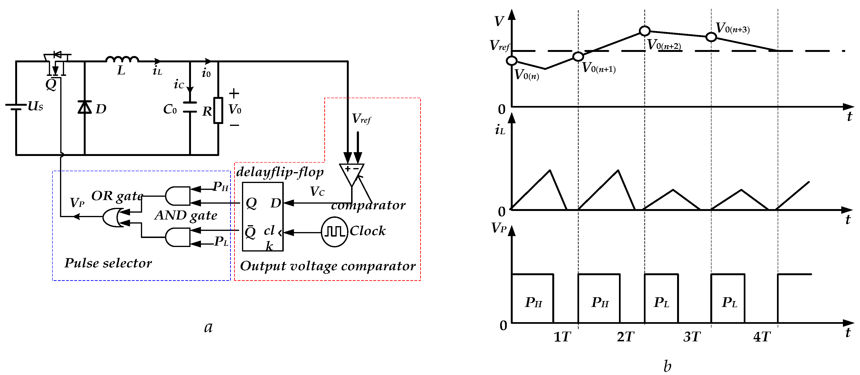
The pulse train (PT) controlled method is put forward based on the linear control theory of the pulse width modulation (PWM) method [29]. The PT controlled method can adjust the output voltage by using two or more sets of a combination of preset control pulses, which has the advantages of simple circuit structure, no compensation network, and fast response. There is a wide application of the PT controlled method in systems with a switching power supply that need high performance [30,31]. Figure 4a shows the schematic diagram of the PT controlled buck converter.
A PT controller consists of a voltage comparator, clock signal, flip-flop delay, and logic gate circuit. The control circuit is simple and easy to implement [32]. The main work process is as follows. In the case that the nth clock trigger signal comes, the comparator transfers the comparison V0 of the output voltage value and the reference value Vref to delay the flip-flop. When V0(n) < Vref, the Q of delay flip-flop outputs 1, outputs 0, and the pulse control chooses PH as the effective control signal, which causes the converter to absorb more energy from the input US, forcing the output voltage to rise; similarly, when the (n + 2)th clock trigger signal comes, the sampling of the output voltage value is V0(n + 2). Because V0(n + 2) > Vref, the Q of delay flip-flop outputs 0, outputs 1, and the pulse control chooses PL as the effective control signal, where the converter absorbs less energy from the input US, forcing the output voltage to decline. The waveforms of the output voltage, inductance current, and control pulse are as shown in Figure 4b.
3.2. The Principle of Capacitor Current Train Pulse
As the full flow of current ripple flows into the output filter capacitance, the phase position of the inductance current ripple can be reflected through the capacitive current. By sampling the capacitive current of converter load side and adding the capacitive current to the output voltage as the condition of pulse choice, one can adjust the hysteresis of output voltage and realize the suppression of low frequency oscillation behavior [33,34].
The accurate circuit model of SRG does not calculate the electromagnetic torque, therefore the model is worthless. Here, the linear model of SRG is applied, since it excludes the influence of magnetic saturation, and the inductance of phase winding is irrelevant to the current. Therefore, the output voltage ripple can be decreased by controlling CC-PT.
In a duty cycle, the inductance of phase is a function of rotor angle. The corresponding phase inductance of SRG in the linear model is expressed as:
where δ = (Lmax−Lmin)/βS, βS is the arc angle of the stator.
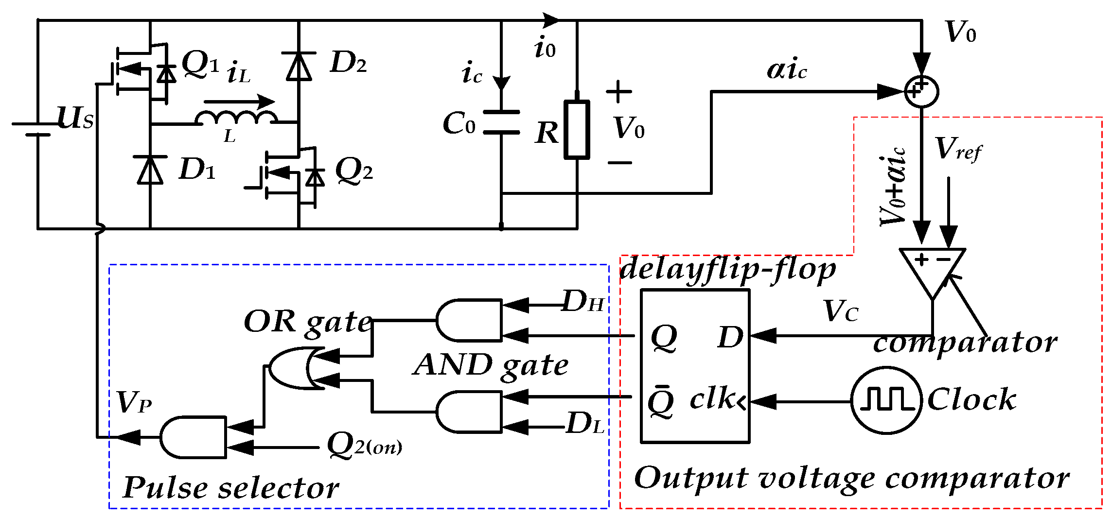
Under the control of CC-PT, the structure of the phase of a SRG power generation system is shown in Figure 5.
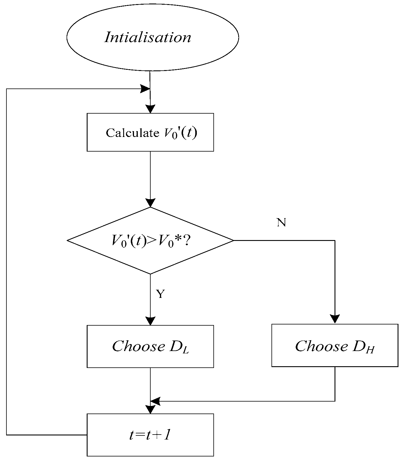
The difference between the CC-PT controlled method and the traditional PT controlled method is in the matter of the sampling information. When the clock signal comes, the sampling circuit samples the output voltage V0 and the capacitor current ic of the circuit, and the sampling results are compared with the reference voltage Vref. When V0 + αic ≤ Vref, the pulse control chooses DH as the effective control signal, which causes the winding of phase A to absorb more energy from the input US, forcing the output voltage to rise; when V0 + αic > Vref, the pulse control chooses DL as the effective control signal, where the converter absorbs less energy from the input US, forcing the output voltage to decline. The selection of pulse control is expressed as:
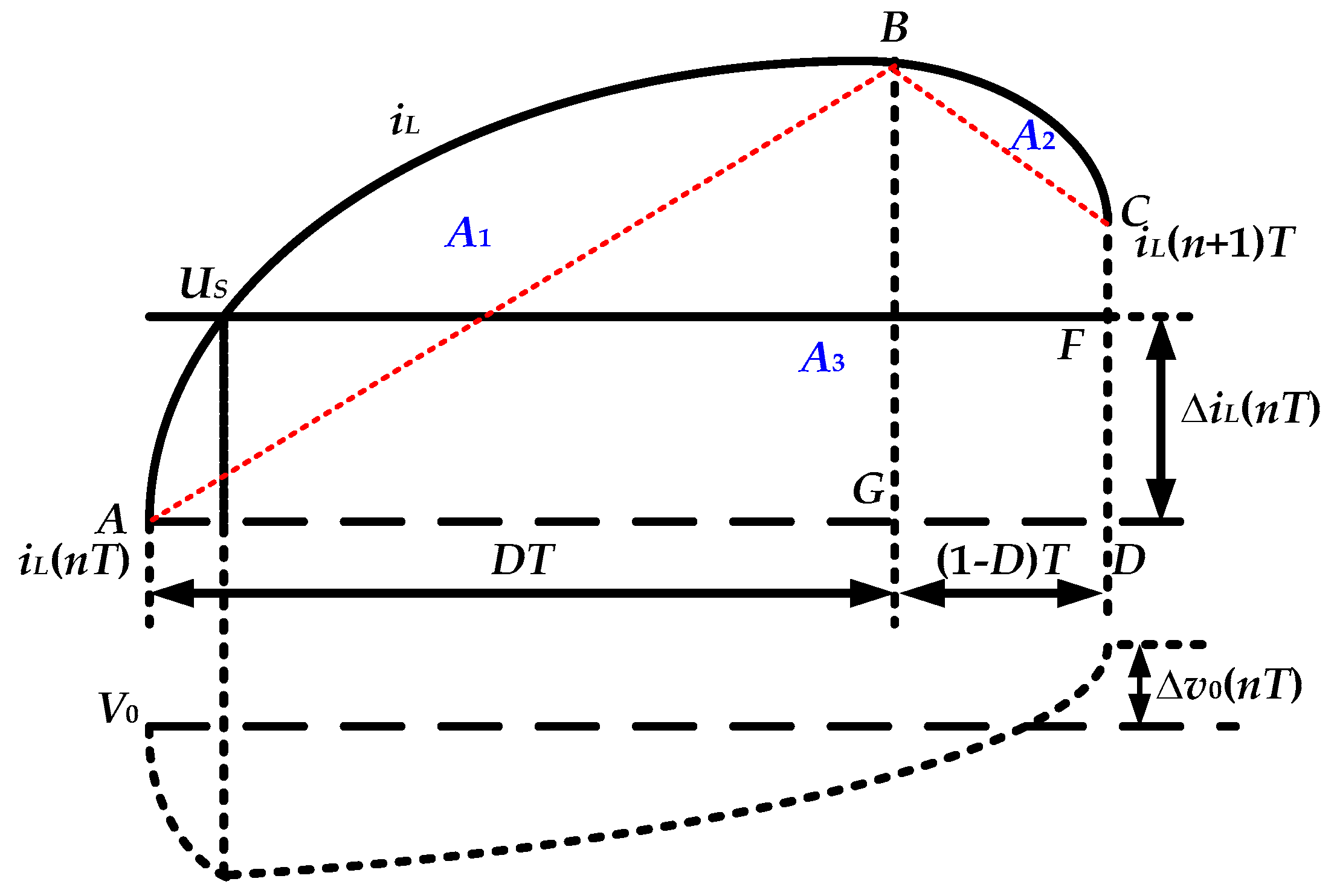
In the circuit shown in Figure 6, the conduction of switches is controlled by cutting the single pipe. Figure 6 shows the waveforms of winding current and output voltage when switch Q2 is conducted (θ2 ≤ θ < θ5). When switch Q2 is conducted, the inductance of winding changes with θ, and the winding current is nonlinearly increased; when switch Q2 is turned off, the winding current is nonlinearly declined. When Q1 is on and θ2 ≤ θ < θ4, the winding of phase A absorbs energy and is excited by US. When θ4 ≤ θ < θ5, the winding of phase A converts the mechanical energy of the rotor to magnetic energy. When Q1 and Q2 are off, the magnetic energy stored in the magnetic field is released from phase A. Thus, the conversion between mechanical energy and electrical energy is completed in the form of magnetic energy.
The winding current iL(θ) satisfies the relationship with the current of the load i0, which is given by;
where Uc is the instantaneous value of the output filter capacitor voltage.
The change of the output voltage (capacitance voltage) in a switching cycle can be determined by:
According to Figure 6, the value of the integral item in the right-hand side of (10) equals the difference between the area of trapezium ABCD and that of the rectangle ADFE. The area of rectangle ADFE is given as:
The area of trapezium ABCD equals the sum of the areas of A1, A2, and A3. The area of A3 can be regarded as L, which equals the constant value L0. The area of trapezium ABCD is expressed as
From (10) to (12), the change in the output voltage can be derived as
with Z2 = , Z1 = .
Since , from (13), the change in the output voltage can be approximately expressed as
The PT controlled method adjusts the output voltage through adjusting the current of winding indirectly. When the output voltage is larger than the reference voltage, the PT controller chooses DH as the control signal, and the output voltage may vary. Similarly, when the output voltage is lower than the reference voltage, the PT controller selects DL as the control signal, and the output voltage may vary as well. The phenomenon of voltage hysteresis leads to the occurrence of low frequency fluctuations in PT control. It can be seen from (14) that the change of output voltage in a switching cycle is mainly determined by ic(nT). The output voltage increases when ic(nT) > 0, otherwise the output voltage declines.
The above analysis shows that the phenomenon of low frequency fluctuations is caused by not adjusting the output voltage in a timely fashion. If the output voltage rises when the system chooses DH, or it declines when the system chooses DL, the low frequency fluctuations can be suppressed. As the full flow of the current ripple of the winding flows into the output filter capacitance, the phase position of the inductance current ripple can be reflected in the capacitive current. In addition, as can be seen from (14), the value of output filter capacitance only affects the output voltage.
From (14), it can be seen that;
where iL(n) is the inductance current at the beginning of the nth switching cycle.
From (15) and the working principle of PT controlled method, the synchronous switching mapping equation of the output voltage and inductance current under the control of CC-PT is shown as:
where:
According to (16), when the system parameters are determined, the combination of high and low pulse signals in a pulse cycle is determined as well. The inductance currents of windings and the output voltage change as the feedback coefficient of the capacitor and the value of load resistance change in each switching cycle, which results in the change of the combination of high and low pulses in the pulse cycle. The Lyapunov exponent function of the CC-PT control system is obtained as:
λ is always less than 0, which indicates that the CC-PT controlled system is in the steady working state when the capacitance current regulation coefficient α and load resistance R change. The output voltage of the system is oscillating at the base level and is measured by defining the standard deviation, which is expressed as:
4. Optimization of Power Generation Efficiency of SRG
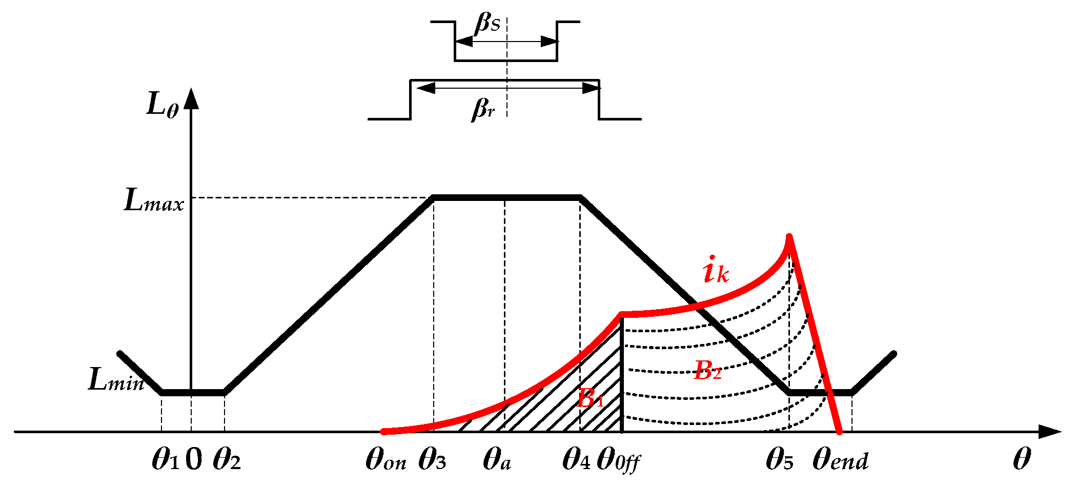
As shown in Figure 7, the ratio of the total instantaneous current value during the phase of electric power generation and excitation is calculated to measure the efficiency of power generation, which is named as ɛ, and it is obtained by;
where ik is the current of phase k.
Therefore, ɛ can be obtained simply by calculating the integration of the phase generation current and the excitation current. In practical applications, θon, θoff, and θend are needed, and the total instantaneous current value during the phase of electric power generation and excitation is calculated, which can be used to determine the efficiency of power generation.
5. Experiment Model and Verification
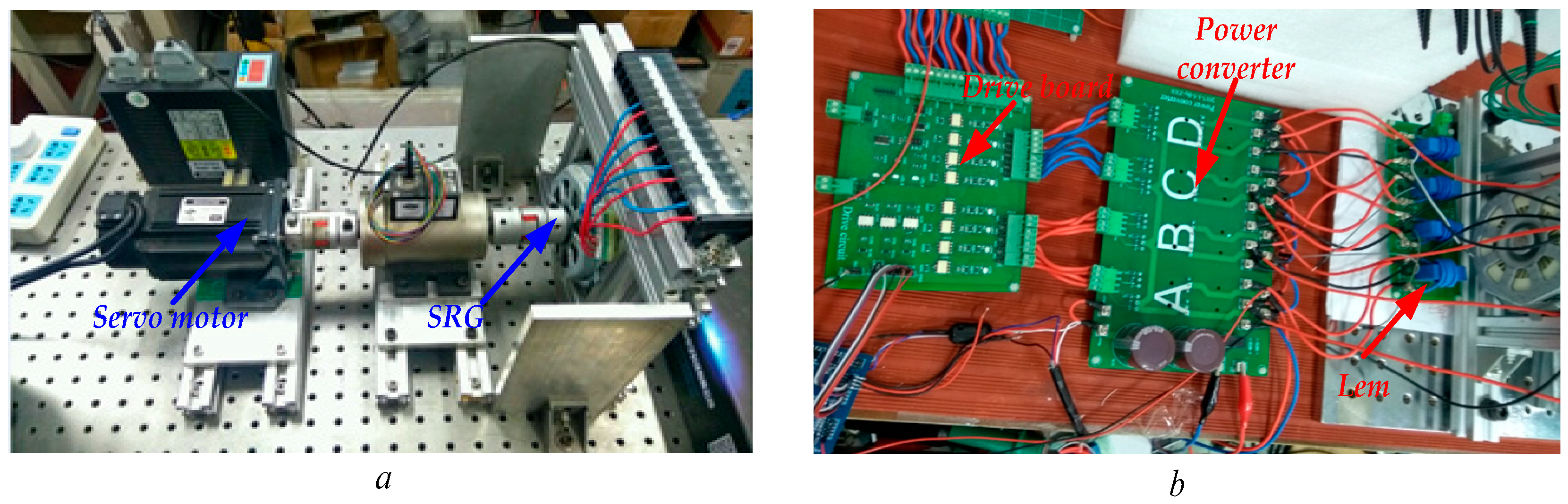
In order to verify the validity of theoretical analysis, this paper has constructed a platform of 8/6 SRG power generation shown in Figure 8a,b which is based on the analysis of SRG and CC-PT control.
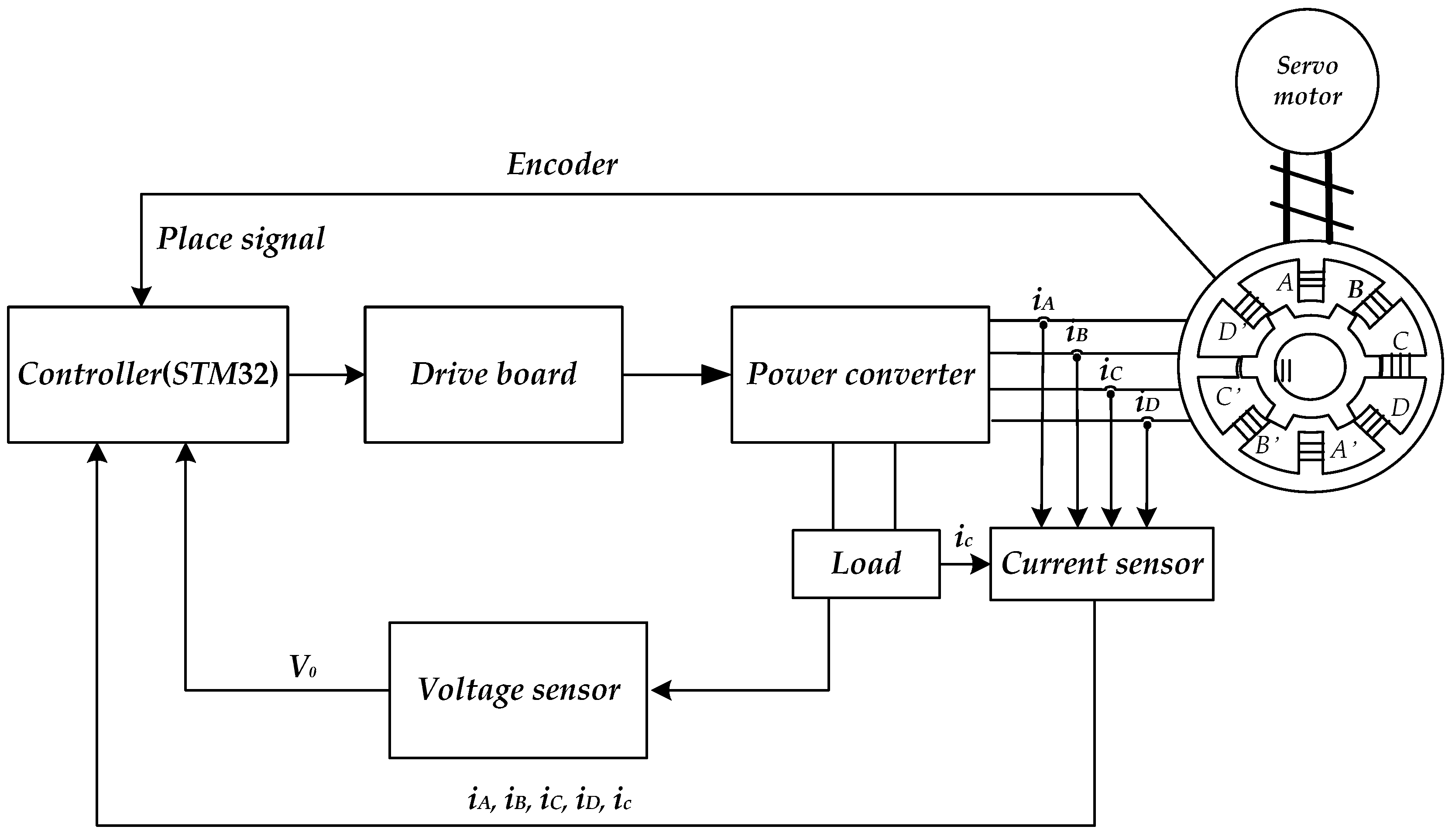
Figure 9 shows the control scheme of the 8/6 SRG system. It consists of a SRG, a servo motor, a drive board, controller (STM32), and so on. The main parts of the circuit are the encoder and sensors, which detect the location of the rotors, the values of current iA, iB, iC, iD, V0, and ic, where ic is the current though the filter capacitor.
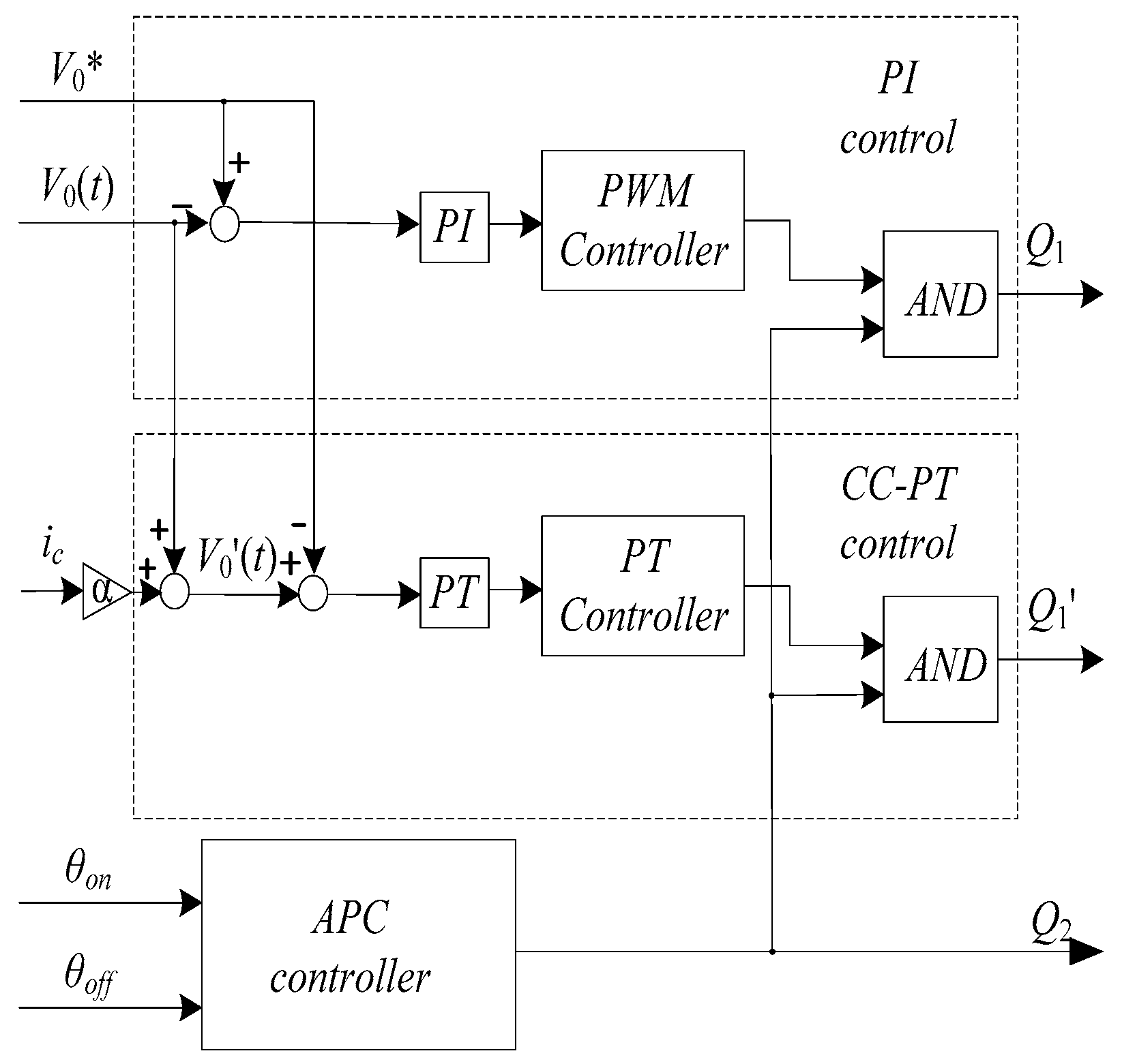
The detail control of PI and CC-PT are shown in Figure 10. It can be easily seen when Q2 is open, which is controlled by the APC controller, and determined by the value of ɛ (the efficiency of power generation). The PI control uses the difference of V0* and V0(t) to form a voltage loop and the PT control leads ic into the control. By limiting the overshoot of ic, the ripple of UC0 is reduced. Figure 11 shows the working principle flowchart of the STM32 controller.
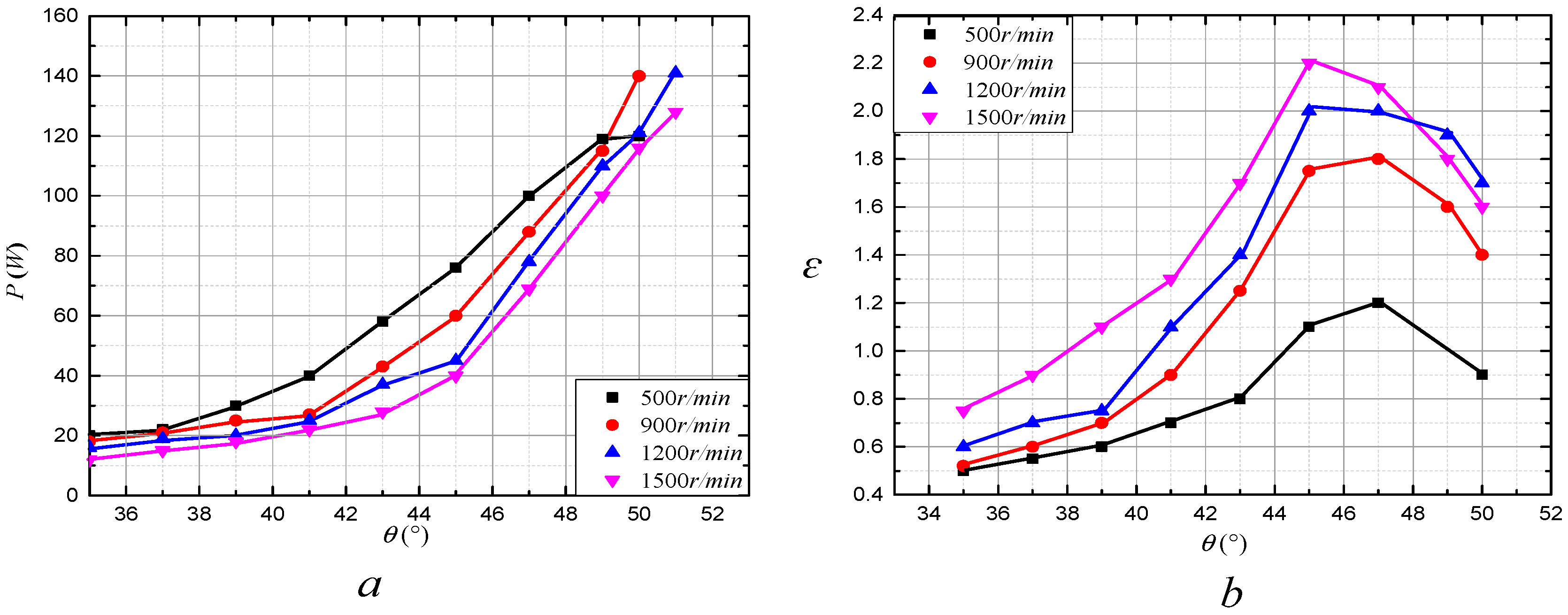
Figure 12a shows the trend of generation power at different speeds and different θoff when θon = 20°. From Figure 12a, it can be seen that at a certain speed, the generation power of SRG gradually increases with the increase of θoff.
Figure 12b shows the trend of ɛ with the change of θoff and speed. It can be seen that ɛ increases as θoff increases at different speeds. However, when θoff reaches a certain value, the value of ɛ decreases, according to which, the optimal θoff can be determined, as well as the optimal net generation power. The optimal θoff at different speeds with the condition of constant θon are shown in Table 1. In the same way, the optimal θon can be obtained at different speeds with the condition of constant θoff, which is also shown in Table 1.
From (18), the feedback coefficient of capacitor α with i ranging from 0 to 1, and the value of the load resistance R with i ranging from 0 to 10, are combined as parameters. With the change of feedback coefficient, the output voltage error approximation is small when the feedback coefficient is larger than 0.2, and the low frequency oscillation can be suppressed by the CC-PT controlled method. In this paper, the PI parameters of traditional PWM control is determined by the critical ratio method (P = 0.5, I = 0.032). In order to compare the ripple of the output voltage with that under PI control, a small capacitor is used in the experiment, the capacitance of which is 680 uF.
In summary, the parameters used in the experiment are shown in Table 2.
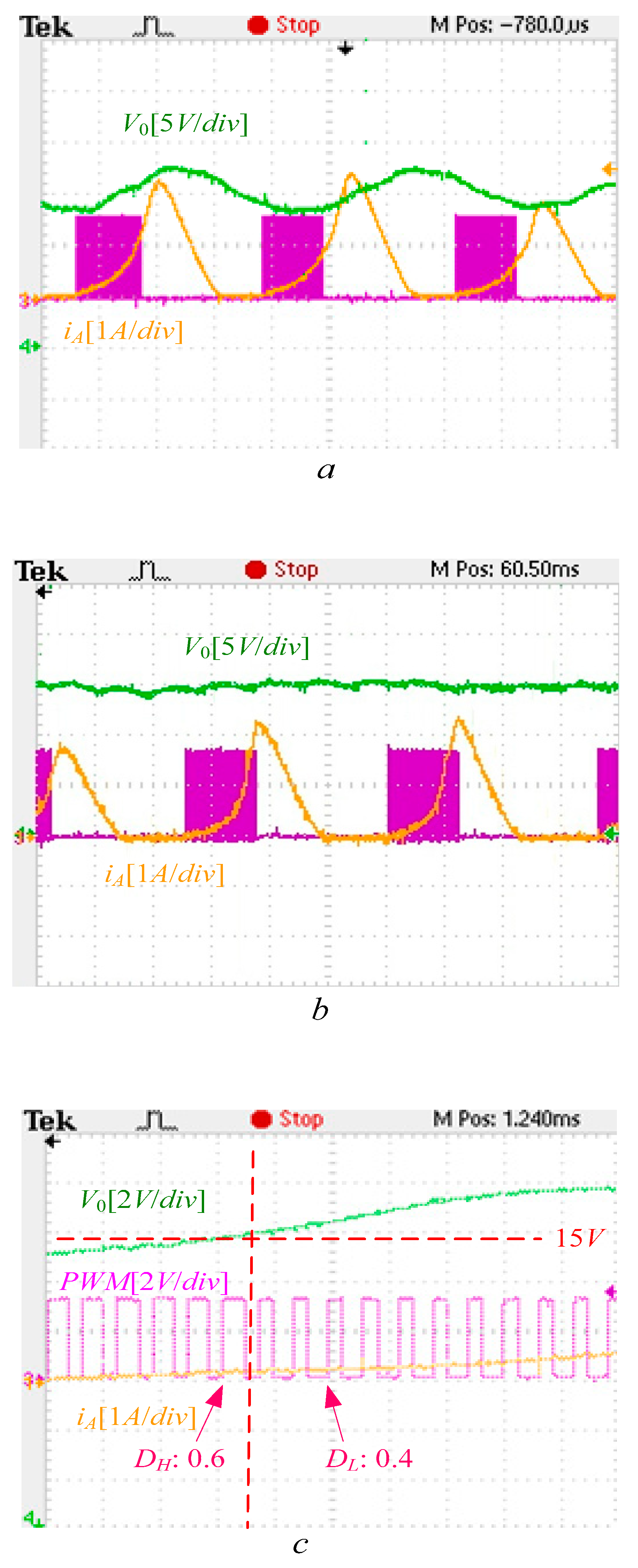
When the desired output voltage V0 = 15 V and the load R = 8 Ω, the experiment waveforms of V0 under PWM control are shown in Figure 13a. It can be seen from Figure 13a, when the SRG runs at a stable state with a constant speed n = 1200 r/min, the ripple of V0 is large, which is up to 5 V.
The parameters of the SRG power generator system under the PT controlled method are: DH = 0.6, DL = 0.4, and f = 6 kHz. Figure 13b shows the experiment waveforms of V0 under the PT controlled method. The ripple of V0 is smaller than that obtained by applying the PI controlled method, but the ripple is still up to 2 V.
Figure 13c shows the details of the PT controlled method. It can be seen that when V0 is smaller than the target value of 15 V, the controller chooses the PWM scheme with DH = 0.6, and the output voltage increases. On the other hand, when the value of V0 is larger than 15 V, the controller chooses the PWM scheme with DL = 0.4 to decrease the output voltage value.
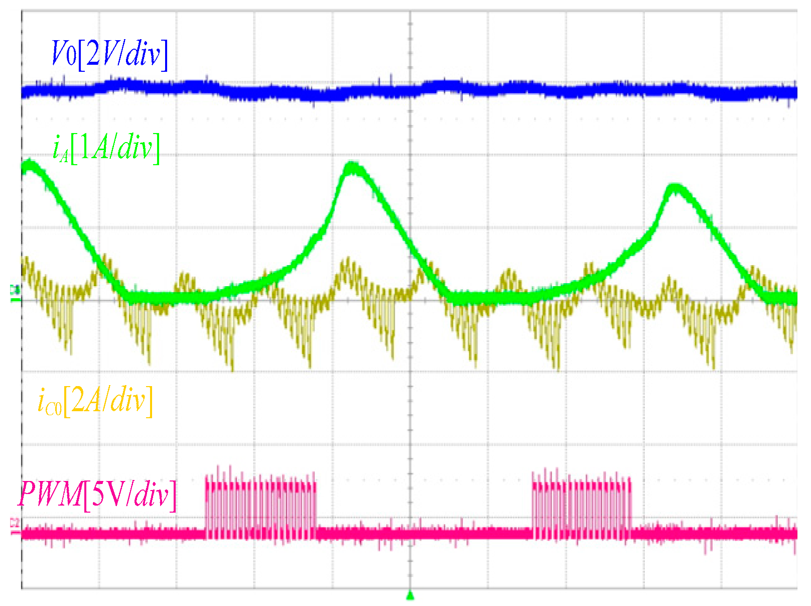
Figure 14 shows the experiment waveforms of V0 under the CC-PT controlled method. The coefficient of ratio α is 1. From (14), the ripple of output voltage Δv0(nT) can be calculated. The largest Δv0(nT) is about ±0.49 V. It can be seen from Figure 14 that the ripple of V0 is the smallest among these three controlled methods. The value of the output voltage ripple is about 1 V, which is consistent with the calculation results of (14).
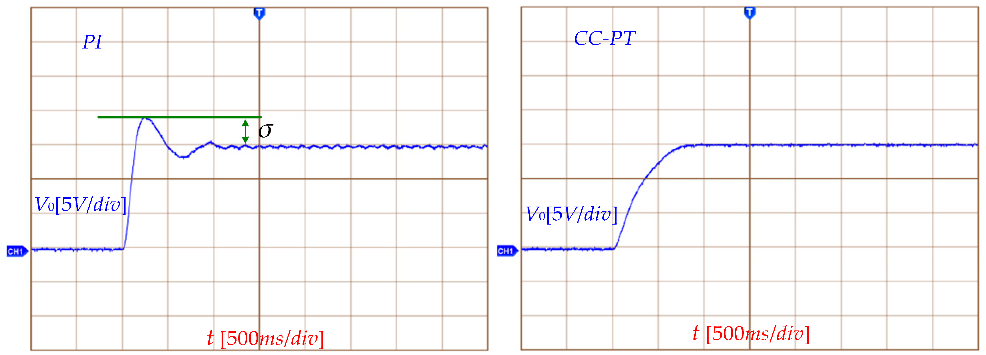
In order to investigate the response of the SRG system starting process, a larger filter capacitance is used in the experiment and the value of it is 0.27 F. Figure 15 shows the starting processes under the control of PI and CC-PT.
It can be easily seen that the output voltage derived by applying the PI controlled method takes about 1.4 s to achieve a stable state. However, the output voltage obtained by using the CC-PT controlled method only takes about 0.7 s to achieve a stable state. Therefore, the system under the CC-PT controlled method responds more quickly than that under the PI controlled method. Meanwhile, from Figure 15, it also can be seen that V0 has a bigger overshoot under the control of PI control, but there is nearly no overshoot of V0 under the control of the CC-PT control. The ripple of V0 derived by the CC-PT controlled method is smaller than that obtained by the PI controlled method.
6. Conclusions
Based on the traditional PT control, a CC-PT controlled method is proposed in this paper to improve the performance of an SRG power system. Through experiment verification, as compared with the traditional SRG power generation system under PWM control, the CC-PT controlled SRG has the following advantages:
- (a)
- The CC-PT controlled method can adjust the output voltage by using two or more sets of combinations of preset control pulses, which has the advantages of simple circuit structure and no compensation network.
- (b)
- The SRG power generation system under the CC-PT controlled method can realize a fast response during start-up. By reasonably configuring the value of DH, the output voltage overshoot can be eliminated.
- (c)
- The start-up phase current is reduced, which makes the system more secure and cost saving. The output voltage ripple is smaller than 5% of the rated value.
Author Contributions
X.Z. and D.Y. suggested the method of CC-PT control used in SRG generation system; M.C. and R.X. analyzed the data. M.C. and X.Z. wrote the paper. K.N. reviewed and edited.
Funding
This research received no external funding.
Acknowledgments
The authors acknowledge the financial support from the Key Laboratory of Control of Power Transmission and Conversion (SJTUM), Ministry of Education (2016AC06).
Conflicts of Interest
The authors declare no conflicts of interest.
References
- Zhao, Z.Y.; Hu, J.; Zuo, J. Performance of wind power industry development in China: A diamondmodel study. Renew. Energy 2009, 34, 2883–2891. [Google Scholar] [CrossRef]
- Liu, Y.; Ren, L.; Li, Y.; Zhao, X.G. The industrial performance of wind power industry in China. Renew. Sustain. Energy Rev. 2015, 43, 644–655. [Google Scholar] [CrossRef]
- Zhao, S.; Nair, N.K.C. Assessment of wind farm models from a transmission system operator perspective using field measurements. IET Renew. Power Gener. 2011, 5, 455–464. [Google Scholar] [CrossRef]
- Cheng, H.; Chen, H.; Wang, Q.; Xu, S.; Yang, S. Design and control of switched reluctance motor drive for electric vehicles. In Proceedings of the 2016 14th International Conference on Control, Automation, Robotics and Vision (ICARCV), Phuket, Thailand, 13–15 November 2016; pp. 1–6. [Google Scholar]
- Dang, J.; Harley, R.G. Sensorless control scheme for ultra high speed switched reluctance machine. In Proceedings of the 2013 IEEE Energy Conversion Congress and Exposition, Denver, CO, USA, 15–19 September 2013; pp. 3830–3836. [Google Scholar]
- Shen, L.; Wu, J.; Yang, S.; Huang, X. Fast flux linkage measurement for switched reluctance motors excluding rotor clamping devices and position sensors. IEEE Trans. Instrum. Meas. 2012, 62, 185–191. [Google Scholar] [CrossRef]
- Chen, H.; Gu, J.J. Switched reluctance motor drive with external rotor for fan in air conditioner. IEEE/ASME Trans. Mechatron. 2013, 18, 1448–1458. [Google Scholar] [CrossRef]
- Song, S.; Zhang, M.; Ge, L. A new fast method for obtaining flux-linkage characteristics of SRM. IEEE Trans. Ind. Electron. 2015, 62, 4105–4117. [Google Scholar] [CrossRef]
- Morimoto, S.; Nakayama, H.; Sanada, M.; Takeda, Y. Sensorless output maximization control for variable-speed wind generation system using ipmsg. IEEE Trans. Ind. Appl. 2015, 41, 60–67. [Google Scholar] [CrossRef]
- Liu, J.; Qiao, F.; Liu, M.; Wu, C. Neural fuzzy control to minimise torque ripple of SRM. Int. J. Model. Identif. Control 2010, 10, 132–137. [Google Scholar] [CrossRef]
- Muyeen, S.M.; Al-Durra, A.; Hasanien, H.M. Application of an adaptive neuro-fuzzy controller for speed control of switched reluctance generator driven by variable speed wind turbine. In Proceedings of the 2015 Modern Electric Power Systems (MEPS), Wroclaw, Poland, 6–9 July 2015; pp. 1–6. [Google Scholar]
- Oliveira, E.S.L.; Aguiar, M.L.; Silva, I.N.D. Strategy to control the terminal voltage of a SRG based on the excitation voltage. IEEE Lat. Am. Trans. 2015, 13, 975–981. [Google Scholar] [CrossRef]
- Liu, Y.Z.; Zhou, Z.; Song, J.L.; Fan, B.J. Based on sliding mode variable structure of studying control for status switching of switched reluctance starter/generator. In Proceedings of the 2015 Chinese Automation Congress, Wuhan, China, 27–29 November 2015; pp. 934–939. [Google Scholar]
- Le-Huy, H.; Chakir, M. Optimizing the performance of a switched reluctance generator by simulation. In Proceedings of the XIX International Conference on Electrical Machines—ICEM 2010, Rome, Italy, 6–8 September 2010; pp. 1–6. [Google Scholar]
- Chang, Y.C.; Liaw, C.M. On the design of power circuit and control scheme for switched reluctance generator. IEEE Trans. Power Electron. 2008, 23, 445–454. [Google Scholar] [CrossRef]
- Liptak, M.; Hrabovcova, V.; Rafajdus, P. Equivalent circuit of switched reluctance generator based on dc series generator. J. Electr. Eng. 2008, 59, 23–28. [Google Scholar]
- Liu, Y.Z.; Zheng, Z.; Sheng, Z.J.; Fan, B.J.; Song, J.L. Study of control strategy for status switching of switched reluctance starter/generator. Electr. Mach. Control 2015. [Google Scholar]
- Ferdowsi, M.; Emadi, A. Pulse regulation control technique for integrated high-quality rectifier-regulators. IEEE Trans. Ind. Electr. 2005, 52, 116–124. [Google Scholar] [CrossRef]
- Ferdowsi, M.; Emadi, A.; Telefus, M.; Davis, C. Pulse regulation control technique for flyback converter. IEEE Trans. Power Electr. 2004, 20, 798–805. [Google Scholar] [CrossRef]
- Khaligh, A.; Rahimi, A.M.; Emadi, A. Modified pulse-adjustment technique to control dc/dc converters driving variable constant-power loads. IEEE Trans. Ind. Electr. 2008, 55, 1133–1146. [Google Scholar] [CrossRef]
- Luo, F.; Ma, D. An integrated switching DC–DC converter with dual-mode pulse-train/pwm control. IEEE Trans. Circuits Syst. II Express Briefs 2015, 56, 152–156. [Google Scholar]
- Wang, J.; Xu, J.; Zhou, G.; Bao, B. Pulse-train-controlled CCM buck converter with small ESR output-capacitor. IEEE Trans. Ind. Electr. 2013, 60, 5875–5881. [Google Scholar] [CrossRef]
- Xu, J.-P.; Mu, Q.-B.; Wang, J.-P.; Qin, M. Output voltage ripple of pulse train controlled DCM buck converter. Electr. Mach. Control 2010, 14, 1–6. [Google Scholar]
- Sha, J.; Xu, D.; Chen, Y.; Xu, J.; Williams, B.W. A peak-capacitor-current pulse-train-controlled buck converter with fast transient response and a wide load range. IEEE Trans. Ind. Electr. 2016, 63, 1528–1538. [Google Scholar] [CrossRef]
- Songyan, K.; Li, K.; Fengping, H.; Zhao, S. Position sensorless technology of switched reluctance motor considering mutual inductances. Trans. China Electrotech. Soc. 2017, 11, 1085–1094. [Google Scholar]
- Gameiro, N.S.; Cardoso, A.J.M. A new method for power converter fault diagnosis in SRM drives. IEEE Trans. Ind. Appl. 2012, 48, 653–662. [Google Scholar] [CrossRef]
- Cai, J.; Deng, Z. A position sensorless control of switched reluctance motors based on phase inductance slope. J. Power Electr. 2013, 13, 264–274. [Google Scholar] [CrossRef]
- Zhang, Z.; Zhaoyu, P.; Feng, G. Research on new control model for switched reluctance motor. In Proceedings of the International Conference on Computer Application and System Modeling, Taiyuan, China, 22–24 October 2010; pp. 198–202. [Google Scholar]
- Sha, J.; Xu, J.; Zhong, S.; Liu, S. Control pulse combination-based analysis of pulse train controlled DCM switching DC–DC converters. IEEE Trans. Ind. Electr. 2015, 62, 246–255. [Google Scholar] [CrossRef]
- Ferdowsi, M.; Emadi, A.; Telefus, M.; Shteynberg, A. Suitability of pulse train control technique for bifred converter. IEEE Trans. Aerosp. Electr. Syst. 2015, 41, 181–189. [Google Scholar] [CrossRef]
- Kapat, S. Analysis and synthesis of reconfigurable digital pulse train control in a DCM buck converter. In Proceedings of the IECON 2014—40th Annual Conference of the IEEE Industrial Electronics Society, Dallas, TX, USA, 29 October–1 November 2014; pp. 1254–1260. [Google Scholar]
- Kapat, S. Voltage-mode digital pulse train control for light load DC-DC converters with spread spectrum. In Proceedings of the 2015 IEEE Applied Power Electronics Conference and Exposition (APEC), Charlotte, NC, USA, 15–19 March 2015; pp. 966–971. [Google Scholar]
- Yang, P.; Bao, B.-C.; Sha, J.; Xu, J.-P. Dynamical mechanism of ramp compensation for switching converter. Acta Phys. Sin. 2013, 62, 709–712. [Google Scholar]
- Sha, J.; Bao, B.-C.; Xu, J.-P.; Gao, Y. Dynamical modeling and border collision bifurcation in pulse train controlled discontinuous conduction mode buck converter. Acta Phys. Sin. 2012, 61, 855–865. [Google Scholar]
Figure 1.
Principles of SRG. (a) Profile of 8/6 SRG; (b) two phases of SRG.

Figure 2.
The main circuit structure diagram of separate excitation.

Figure 3.
The waveforms of the phase current using three control methods. (a) APC control method; (b) CCC control method; (c) PWM control method.
Figure 3.
The waveforms of the phase current using three control methods. (a) APC control method; (b) CCC control method; (c) PWM control method.

Figure 4.
The principle of PT and CC-PT control. (a)VM-PT controlled Buck converter schematic; (b) schematic of working principle.
Figure 4.
The principle of PT and CC-PT control. (a)VM-PT controlled Buck converter schematic; (b) schematic of working principle.

Figure 5.
The structure of SRG power system under the control of CC-PT.

Figure 6.
The waveforms of winding current and output voltage during a switching cycle.

Figure 7.
The schematic diagram of ɛ.

Figure 8.
The photograph of the experimental platform of SRG power generation. (a) Experiment platform of SRG; (b) control circuits and the power converter.
Figure 8.
The photograph of the experimental platform of SRG power generation. (a) Experiment platform of SRG; (b) control circuits and the power converter.

Figure 9.
The control scheme of the 8/6 SRG system.

Figure 10.
SRG controller.

Figure 11.
Flowchart of the STM32 controller.

Figure 12.
Optimize the θoff. (a) The trend of generation power; (b) the trend of ɛ.

Figure 13.
The experiment waveforms of SRG. (a) Experiment waveforms of output voltage V0 under PWM control; (b) experiment waveforms of output voltage V0 under PT control; (c) the details of experiment waveforms under PT control.
Figure 13.
The experiment waveforms of SRG. (a) Experiment waveforms of output voltage V0 under PWM control; (b) experiment waveforms of output voltage V0 under PT control; (c) the details of experiment waveforms under PT control.

Figure 14.
The experiment waveforms of output voltage under CC-PT control.

Figure 15.
The starting process under the control of PI and CC-PT.


Table 1.
The optimal θon and θoff.
| n, r/min | θon, deg | θoff, deg |
|---|---|---|
| 500 | 25 | 47 |
| 900 | 23 | 47 |
| 1200 | 25 | 45 |
| 1500 | 25 | 45 |
Table 2.
Parameters of experiment model.
| Parameters | Value | Parameters | Value |
|---|---|---|---|
| m | 4 | R, Ω | 8 |
| Ns | 8 | C, uF | 680 |
| Nr | 6 | P | 0.5 |
| Us, V | 80 | I | 0.032 |
| n,r/min | 1200 | DH | 0.6 |
| θon, deg | 25 | DL | 0.4 |
| θoff, deg | 45 | f, Hz | 6000 |
© 2018 by the authors. Licensee MDPI, Basel, Switzerland. This article is an open access article distributed under the terms and conditions of the Creative Commons Attribution (CC BY) license (http://creativecommons.org/licenses/by/4.0/).
Share and Cite
MDPI and ACS Style
Zan, X.; Cui, M.; Yu, D.; Xu, R.; Ni, K. Improvement of the Response Speed for Switched Reluctance Generation System Based on Modified PT Control. Energies 2018, 11, 2049. https://doi.org/10.3390/en11082049
AMA Style
Zan X, Cui M, Yu D, Xu R, Ni K. Improvement of the Response Speed for Switched Reluctance Generation System Based on Modified PT Control. Energies. 2018; 11(8):2049. https://doi.org/10.3390/en11082049
Chicago/Turabian StyleZan, Xiaoshu, Mingliang Cui, Dongsheng Yu, Ruidong Xu, and Kai Ni. 2018. "Improvement of the Response Speed for Switched Reluctance Generation System Based on Modified PT Control" Energies 11, no. 8: 2049. https://doi.org/10.3390/en11082049
Note that from the first issue of 2016, this journal uses article numbers instead of page numbers. See further details here.