Article

SDC-Infiltrated Microporous Silver Membrane with Superior Resistance to Thermal Agglomeration for Cathode-Supported Solid Oxide Fuel Cells

1
School of Mechanical & Aerospace Engineering, Nanyang Technological University, 50 Nanyang Avenue, Singapore 639798, Singapore
2
College of Chemistry and Environmental Engineering, Shenzhen University, Nanhai Ave 3688, Shenzhen 518060, China
3
Singapore Institute of Manufacturing Technology, 73 Nanyang Drive, Singapore 637662, Singapore
4
School of Mechanical Engineering, Chung-Ang University, 84 Heukseok-ro, Heukseok-dong, Dongjak-gu, Seoul 06974, Korea
*
Authors to whom correspondence should be addressed.
Energies 2018, 11(9), 2181; https://doi.org/10.3390/en11092181
Submission received: 15 July 2018 / Revised: 2 August 2018 / Accepted: 18 August 2018 / Published: 21 August 2018
(This article belongs to the Section F: Electrical Engineering)

Abstract

:
This work presents a microporous silver cathode membrane reinforced with infiltration of samarium-doped ceria (SDC). The ion-conducting SDC effectively confines the surface of a porous silver membrane to maintain microporous structure and prevents the electrode agglomeration. SDC precursor solution is fired together with silver membrane at 700 °C for 2 h and formed as a nanocrystalline SDC on the silver pore surface. The SDC-infiltrated microporous silver membrane shows superior resistance to agglomeration without noticeable change in microstructures even at 900 °C for 12 h, which makes it promising for the application of solid oxide fuel cells as a cathode support.

1. Introduction

The use of catalytically active metals can likely be an alternative to oxide electrodes in solid oxide fuel cells (SOFCs) operating at low temperatures (<500 °C). Nanoporous platinum-based thin films have been frequently used as electrodes for its superior catalytic activity at low temperatures [1,2,3], but the cost ineffectiveness is an obvious drawback. In this regard, silver can be a good candidate as a metallic cathode for low temperature SOFCs due to its high electrical conductivity, oxygen diffusivity, catalytic activity for oxygen reduction reaction (ORR), and much lower price than platinum. However, the extremely poor thermal stability of silver makes it challenging to maintain its overall porous structure at elevated temperatures [4,5,6]. The thermal agglomeration of porous silver results in loss of triple phase boundary (TPB) density and gas diffusion limitation, consequently making a degradation of overall fuel cell performance.
One effective method to maintain porous structure is coating a thin layer of ion-conducting oxide over the metal surface using vacuum-based deposition processes [7,8,9,10,11,12]. The thin oxide layer acts as a physical confinement to hinder the thermally-driven agglomeration. Another method to stabilize the morphology of porous cathode is solution infiltration, which is preferred because of the flexibility of materials selection and cost-effective process [13,14,15]. The infiltrated oxides were reported not only to increase the TPB density, but also to promote oxygen surface adsorption process, which can improve the ORR.
A high-performance SOFC operating at temperature below 500 °C was still relying on the micro-SOFCs with a nanoscale thin film electrolyte [16,17,18,19,20]. As the thin film electrolyte is always deposited at a high temperature by atomic layer deposition (ALD) or pulsed laser deposition (PLD) [21,22,23,24], thermally-induced residual stress is inevitably generated, and results in membrane fracture during fabrication or fuel cell operation [16,25,26]. In our previous study, a new architecture of silicon-based micro-SOFCs with circular membrane reinforced with a tapered thin edge support was developed to further reduce the residual stress [20]. However, nanoscale thin and freestanding electrolyte membrane was still very fragile, leading to a low membrane survival rate, especially for the large-scale membranes. Therefore, developing an alternative substrate or structure is worthwhile for high-performance SOFCs.
In this work, we demonstrated that a SDC-infiltrated microporous silver membrane can be used as an efficient cathode support which is sustainable at a high temperature up to 900 °C without significant thermal agglomeration. SDC was selected for its high ionic conductivity, catalytic activity, and low phase formation temperature. The infiltrated SDC solution was formed as a thin layer of scattered nanoparticles on the porous silver surface, acting as physical confinement to hinder agglomeration of silver. In addition, SDC-infiltrated silver cathode-supported SOFC was also demonstrated by applying a 300 nm-thick yttria-stabilized zirconia (YSZ) electrolyte and a nanoporous platinum anode to verify its functionality.

2. Experimental

2.1. Preparation of SDC Precursor Solution and SDC Infiltration Process

Commercial silver filter membrane with nominal filterability to be 0.2 µm of particle size (SKC Asia HSE Sampling Technologies Pte Ltd., Singapore) was used for the study. The thickness of the silver membrane was 60 µm, and the filter diameter was 13 mm. The SDC precursor solution was prepared by dissolving stoichiometric amounts (molar ratio of 4:1 for Sm3+:Ce3+) of samarium (III) nitrate hexahydrate (Sm(NO3)3·6H2O, Alfa Aesar, 99.9%) and cerium (III) nitrate hexahydrate (Ce(NO3)3·6H2O, Sigma Aldrich, 99%) into deionized water with stirring. Triton X-100 (Bio-Rad Laboratories Pte Ltd., Singapore) was added to the nitrate solution as a surfactant. The porous silver membrane was first immersed into the solution for 5 min, and then dried at room temperature. One step of infiltration process was performed in fabricating SDC-infiltrated Ag membrane. The dried SDC-infiltrated Ag membrane was baked at 110 °C for 1 h, followed by firing at 700 °C for 2 h to decompose the nitrate and form crystalline SDC.
The crystallinity of the SDC fired at 110 °C and fired at 700 °C were identified by X-ray diffractometer (XRD, PANalytical Empyrean) with Cu Kα radiation source in the 2θ range from 20° to 80°. The morphologies were characterized by field emission scanning electron microscopy (FESEM, JSM-7600F, JEOL, Tokyo, Japan) using 10 kV as operating voltage. The energy dispersive X-ray spectroscopy (EDS, JEOL 7600F with energy-dispersive X-ray spectroscopic detectors) was utilized for characterizing the composition and element distribution of SDC-infiltrated silver membrane.

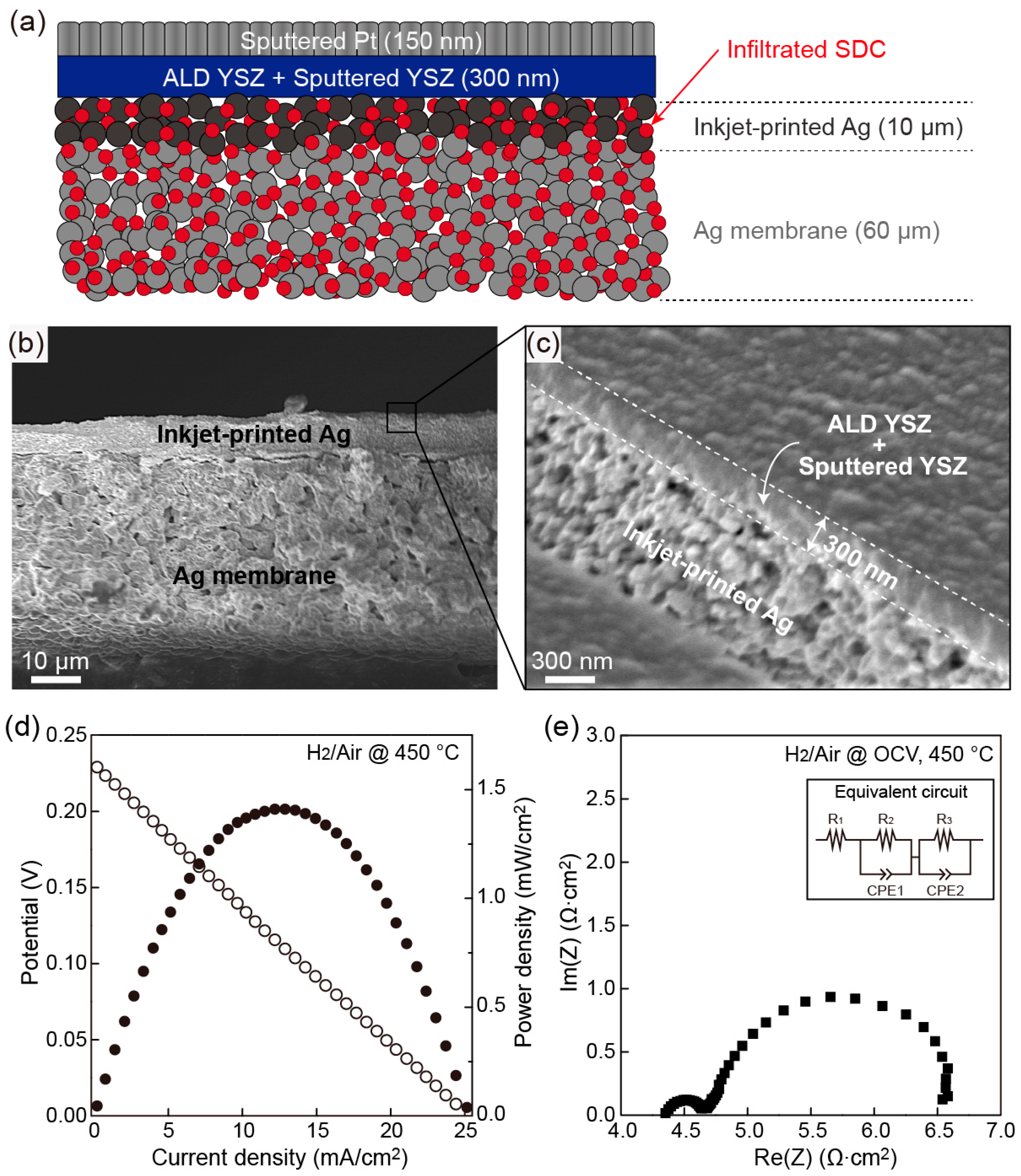
2.2. Fabrication of SDC-Infiltrated Silver Cathode-Supported Cell

A 10 µm-thick silver nanoparticle thin film was first deposited on the silver membrane by inkjet-printing, followed by SDC infiltration process. Inkjet-printed silver nanoparticles were covered on the top of the silver membrane to narrow down the open pores for YSZ electrolyte deposition. A 100 nm-thick and 200 nm-thick YSZ thin film were subsequently deposited on the top of the inkjet-printed silver thin film by atomic layer deposition and sputtering, respectively. The sputtered platinum was then deposited on the YSZ electrolyte as an anode.

2.3. Electrochemical Characterization

SDC-infiltrated silver cathode-supported cell was characterized under fuel cell operation condition with dry hydrogen as fuel and ambient air as oxidant at 450 °C. The polarization curves and polarization resistances (Rp) were measured using a potentiostat (Solartron 1470E, Solartron Analytical, USA) with a frequency analyzer (Solartron 1255B, Solartron Analytical, USA).

3. Result and Discussion

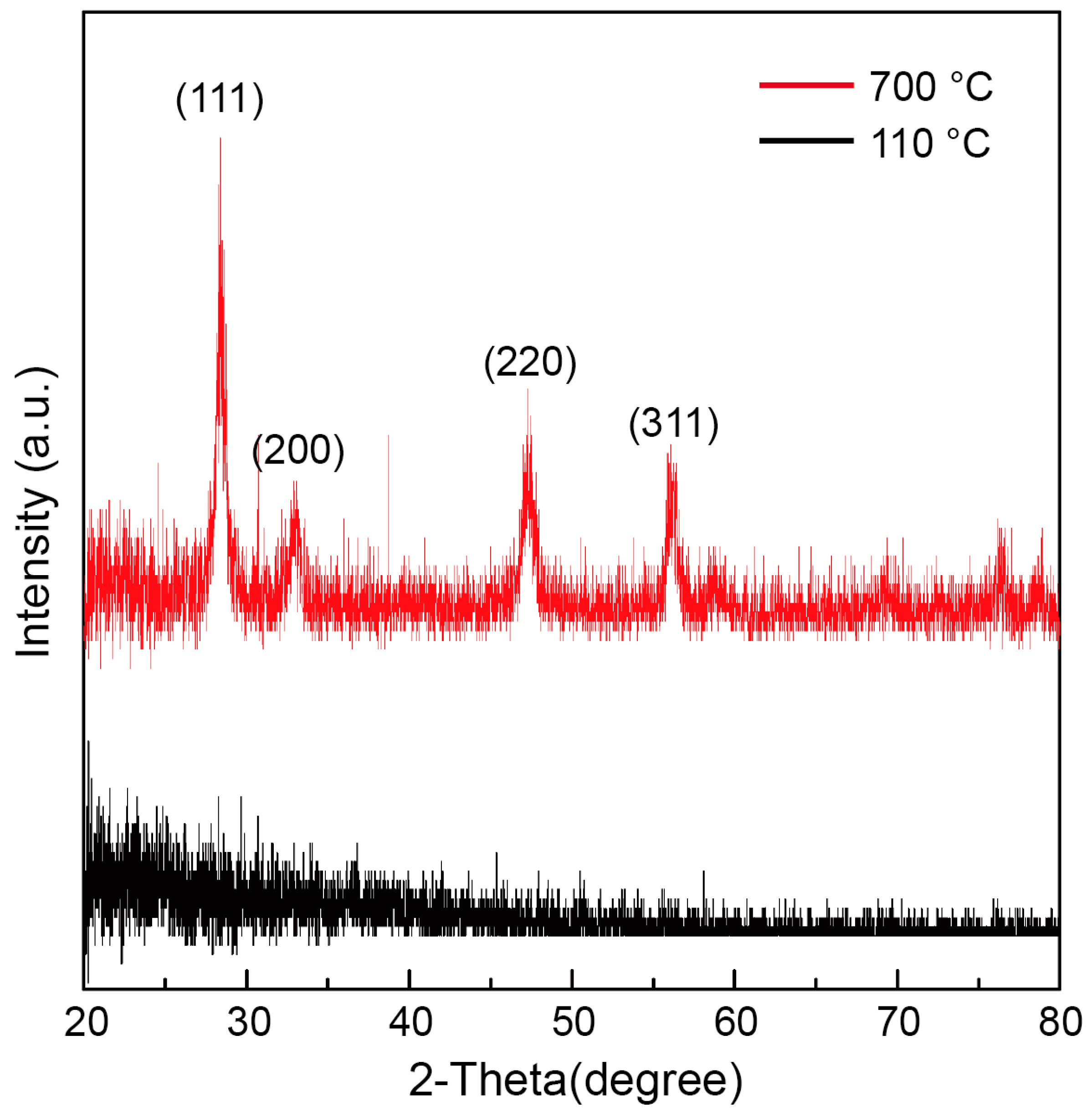
3.1. Crystallinity of SDC Precursor Solution

The crystal structures of SDC precursor solution were examined using XRD, as shown in Figure 1. The samples were prepared on the (100) Si wafer followed by baking at 110 °C and firing at 700 °C. The cubic fluorite structure with (111) preferred orientation consists of SDC phases appeared at fired temperature of 700 °C for 2 h (JCPDS #75-0158), while an amorphous phase was observed when the SDC solution was only baked at 110 °C. In addition, the average crystallite size of the fired SDC was around 15 nm, which was determined by Scherrer equation from XRD data. XRD results showing that the SDC solution fired at 700 °C is cubic nanocrystalline structure, which was reported to have high ionic conductivity [27].

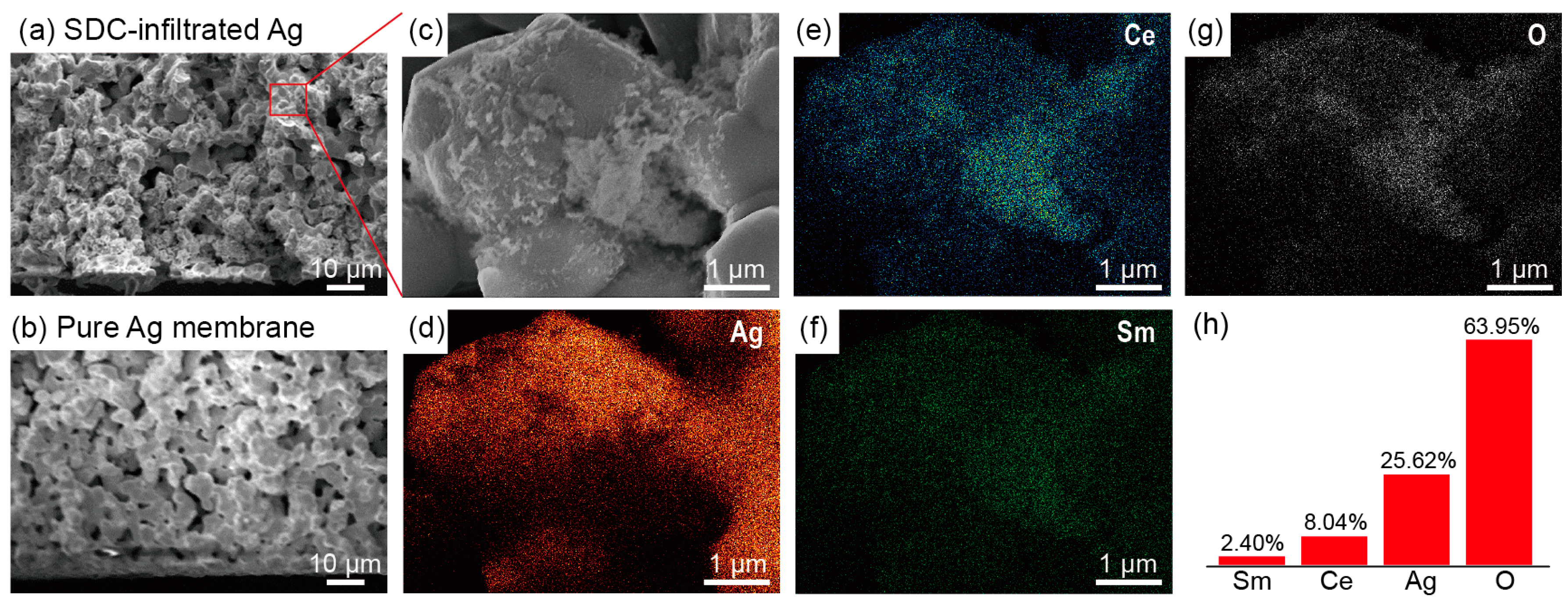
3.2. Morphology and Element Distribution of SDC-Infiltrated Silver Membrane

Figure 2a shows the cross-sectional FESEM images of SDC-infiltrated silver membrane fired at 700 °C. The micro-pores were well-maintained at 700 °C, and showed similar microstructures to that of the pure silver membrane (Figure 2b). The discretely distributed SDC was coated on the silver surface to form a physical confinement to prevent agglomeration at high temperature (Figure 2c). The EDS mapping results shown in Figure 2d–h further confirmed the distribution of SDC on the silver surface. Even though some big SDC clusters were formed, the infiltrated SDC still discretely distributed over the entire silver surface. In addition, the atomic ratio of Ce to Sm was close to 4, which were consistent with the ratio of synthesized SDC precursor solution.

3.3. Thermo-Morphological Stability of SDC-Infiltrated Silver Membrane

The thermo-morphological stability of SDC-infiltrated silver membrane fired at 700 °C was verified under extremely high temperature and long term heating. The surface morphology changes after heating at 700, 800, and 900 °C for 12 h were shown in Figure 3. Serious agglomeration of the pure silver membrane was observed after heating at temperature above 700 °C. The micro-pores were tended to be collapsed and became a dense film at 900 °C. On the other hand, the SDC-infiltrated silver membrane greatly retained its microporous structure even heated at temperature of 900 °C, which is very close to the melting temperature of silver (961 °C). Therefore, the infiltrated SDC formed a physical confinement to prevent the microporous structure from thermally-driven agglomeration. This result justified the superior effectiveness of SDC infiltration in maintaining the micro-pores of silver.

3.4. Electrochemical Characterization of SDC-Infiltrated Silver Cathode-Supported Cell

The schematic of the SDC-infiltrated silver cathode-supported cell is shown in Figure 4a, and the cross-sectional FESEM images of the SDC-infiltrated silver cathode-supported cell are shown in Figure 4b,c. The silver nanoparticles thin film was fully covered on the top of silver membrane surface and a 300 nm-thick YSZ electrolyte layer was deposited on the silver nanoparticles thin film as an electrolyte. Figure 4d shows the polarization curve of SDC-infiltrated silver cathode-supported cell. The open circuit voltage (OCV) obtained from the cell was only 0.23 V, which was much smaller than a typical SOFCs (~1 V), and the peak power density only reached to 1.4 mW/cm2. The low OCV was possibly due to the current leakage through the pinhole of YSZ electrolyte or the silver ion migration through YSZ during fuel cell operation. Silver is highly mobile at elevated temperature, and therefore, easily diffuses into electrolyte through the pinholes. Moreover, silver ion also tends to migrate toward to the platinum anode when applying an electric field, making an electrical conduction bridge between silver cathode and platinum anode. To overcome the silver migration into the electrolyte, thicker electrolyte or a blocking layer can be considered.
Recently, a high-performance SOFC using thicker SDC electrolyte with thickness of 11.8 μm was reported and the peak power density of around 1.1 W/cm2 with the ohmic resistance of 9.05 Ω cm2 was achieved at 500 °C [28]. In this work, the electrolyte thickness is only 300 nm; it is therefore challenging to have such a dense and pinhole-free thin layer on a porous silver membrane. In addition, the ohmic and polarization resistance of the SDC-infiltrated silver cathode-supported cell using 300 nm-thick YSZ electrolyte are 4.4 and 2.1 Ω·cm2, respectively (Figure 4e). These high resistance values may also come from the current leakage under fuel cell operation. Therefore, by increasing the thickness of electrolyte to micrometer-scale to avoid the current leakage and silver migration, comparable performance to the typical micro-SOFCs can be achieved.

4. Conclusions

We demonstrated a feasibility of SDC-infiltrated silver as a cathode support with superior thermo-morphological stability at high temperature. The morphology of SDC-infiltrated silver membrane was well maintained without thermal agglomeration even after heating at 900 °C for 12 h, while the initial morphology of pure silver membrane was significantly agglomerated at heating temperature above 700 °C. Cubic nanocrystalline SDC with a correct composition was coated on a porous silver membrane and discretely distributed to maintain the porous structure from thermally-driven agglomeration. The SDC-infiltrated silver cathode-supported cell with 300 nm-thick YSZ electrolyte showed only OCV of 0.23 V and low power density of 1.5 mW/cm2 at 450 °C. However, the cell performance can be possibly further improved by using a thicker electrolyte layer.

Author Contributions

T.-H.L. conducted experiments and data analysis for the current research. J.D.B. gave his effort to analyze the results and improve figures and context. L.F. and F.E.W. have provided helpful comments for data analysis. As co-corresponding authors, P.-C.S. and S.H.L. have provided useful suggestions and comments to improve the quality of the current manuscript.

Acknowledgments

This research was supported by the Chung-Ang University research grant in 2016. Also, this research was supported by the Korea Institute for Advancement of Technology (KIAT) grant funded by the Korea Government—Ministry of Trade Industry and Energy (MOTIE), (No. N0001075).

Conflicts of Interest

The authors declare no conflict of interest.

References

  1. Su, P.C.; Chao, C.C.; Shim, J.H.; Fasching, R.; Prinz, F.B. Solid oxide fuel cell with corrugated thin film electrolyte. Nano Lett. 2008, 8, 2289–2292. [Google Scholar] [CrossRef] [PubMed]
  2. Kang, S.; Su, P.C.; Park, Y.I.; Saito, Y.; Prinz, F.B. Thin-Film Solid Oxide Fuel Cells on Porous Nickel Substrates with Multistage Nanohole Array. J. Electrochem. Soc. 2006, 153, A554. [Google Scholar] [CrossRef]
  3. Rey-Mermet, S.; Muralt, P. Solid oxide fuel cell membranes supported by nickel grid anode. Solid State Ion. 2008, 179, 1497–1500. [Google Scholar] [CrossRef]
  4. Moon, Y.J.; Kang, H.; Kang, K.; Moon, S.J.; Hwang, J.Y. Effect of Thickness on Surface Morphology of Silver Nanoparticle Layer During Furnace Sintering. J. Electron. Mater. 2015, 44, 1192–1199. [Google Scholar] [CrossRef]
  5. Simrick, N.J.; Kilner, J.A.; Atkinson, A. Thermal stability of silver thin films on zirconia substrates. Thin Solid Films 2012, 520, 2855–2867. [Google Scholar] [CrossRef]
  6. West, M.; Manthiram, A. Synthesis of 3-dimensional silver networks and their application in solid oxide fuel cells. Int. J. Hydrogen Energy 2015, 40, 4234–4240. [Google Scholar] [CrossRef]
  7. Lee, Y.H.; Cho, G.Y.; Chang, I.; Ji, S.; Kim, Y.B.; Cha, S.W. Platinum-based nanocomposite electrodes for low-temperature solid oxide fuel cells with extended lifetime. J. Power Sources 2016, 307, 289–296. [Google Scholar] [CrossRef]
  8. Choi, H.J.; Kim, M.; Neoh, K.C.; Jang, D.Y.; Kim, H.J.; Shin, J.M.; Kim, G.T.; Shim, J.H. High-Performance Silver Cathode Surface Treated with Scandia-Stabilized Zirconia Nanoparticles for Intermediate Temperature Solid Oxide Fuel Cells. Adv. Energy Mater. 2017, 7. [Google Scholar] [CrossRef]
  9. Li, Y.K.; Choi, H.J.; Kim, H.K.; Chean, N.K.; Kim, M.; Koo, J.; Jeong, H.J.; Jang, D.Y.; Shim, J.H. Nanoporous silver cathodes surface-treated by atomic layer deposition of Y:ZrO2 for high-performance low-temperature solid oxide fuel cells. J. Power Sources 2015, 295, 175–181. [Google Scholar] [CrossRef]
  10. Neoh, K.C.; Han, G.D.; Kim, M.; Kim, J.W.; Choi, H.J.; Park, S.W.; Shim, J.H. Nanoporous silver cathode surface treated by atomic layer deposition of CeOx for low-temperature solid oxide fuel cells. Nanotechnology 2016, 27. [Google Scholar] [CrossRef] [PubMed]
  11. Chang, I.; Ji, S.; Park, J.; Lee, M.H.; Cha, S.W. Ultrathin YSZ Coating on Pt Cathode for High Thermal Stability and Enhanced Oxygen Reduction Reaction Activity. Adv. Energy Mater. 2015, 5. [Google Scholar] [CrossRef]
  12. Liu, K.-Y.; Fan, L.; Yu, C.-C.; Su, P.-C. Thermal stability and performance enhancement of nano-porous platinum cathode in solid oxide fuel cells by nanoscale ZrO2 capping. Electrochem. Commun. 2015, 56, 65–69. [Google Scholar] [CrossRef]
  13. Jiang, S.P. Nanoscale and nano-structured electrodes of solid oxide fuel cells by infiltration: Advances and challenges. Int. J. Hydrogen Energy 2012, 37, 449–470. [Google Scholar] [CrossRef]
  14. Jiang, Z.Y.; Xia, C.R.; Chen, F.L. Nano-structured composite cathodes for intermediate-temperature solid oxide fuel cells via an infiltration/impregnation technique. Electrochim. Acta 2010, 55, 3595–3605. [Google Scholar] [CrossRef]
  15. Ding, D.; Li, X.X.; Lai, S.Y.; Gerdes, K.; Liu, M.L. Enhancing SOFC cathode performance by surface modification through infiltration. Energy Environ. Sci. 2014, 7, 552–575. [Google Scholar] [CrossRef]
  16. Huang, H.; Nakamura, M.; Su, P.C.; Fasching, R.; Saito, Y.; Prinz, F.B. High-performance ultrathin solid oxide fuel cells for low-temperature operation. J. Electrochem. Soc. 2007, 154, B20–B24. [Google Scholar] [CrossRef]
  17. Beckel, D.; Bieberle-Hutter, A.; Harvey, A.; Infortuna, A.; Muecke, U.P.; Prestat, M.; Rupp, J.L.M.; Gauckler, L.J. Thin films for micro solid oxide fuel cells. J. Power Sources 2007, 173, 325–345. [Google Scholar] [CrossRef]
  18. Takagi, Y.; Lai, B.-K.; Kerman, K.; Ramanathan, S. Low temperature thin film solid oxide fuel cells with nanoporous ruthenium anodes for direct methane operation. Energy Environ. Sci. 2011, 4, 3473–3478. [Google Scholar] [CrossRef]
  19. Garbayo, I.; Pla, D.; Morata, A.; Fonseca, L.; Sabate, N.; Tarancon, A. Full ceramic micro solid oxide fuel cells: Towards more reliable MEMS power generators operating at high temperatures. Energy Environ. Sci. 2014, 7, 3617–3629. [Google Scholar] [CrossRef]
  20. Baek, J.D.; Yoon, Y.-J.; Lee, W.; Su, P.-C. A circular membrane for nano thin film micro solid oxide fuel cells with enhanced mechanical stability. Energy Environ. Sci. 2015, 8, 3374–3380. [Google Scholar] [CrossRef]
  21. Bernay, C.; Ringuede, A.; Colomban, P.; Lincot, D.; Cassir, M. Yttria-doped zirconia thin films deposited by atomic layer deposition ALD: A structural, morphological and electrical characterisation. J. Phys. Chem. Solids 2003, 64, 1761–1770. [Google Scholar] [CrossRef]
  22. Shim, J.H.; Chao, C.C.; Huang, H.; Prinz, F.B. Atomic layer deposition of yttria-stabilized zirconia for solid oxide fuel cells. Chem. Mater. 2007, 19, 3850–3854. [Google Scholar] [CrossRef]
  23. Heiroth, S.; Lippert, T.; Wokaun, A.; Döbeli, M.; Rupp, J.L.M.; Scherrer, B.; Gauckler, L.J. Yttria-stabilized zirconia thin films by pulsed laser deposition: Microstructural and compositional control. J. Eur. Ceram. Soc. 2010, 30, 489–495. [Google Scholar] [CrossRef]
  24. Pergolesi, D.; Fabbri, E.; D’Epifanio, A.; Di Bartolomeo, E.; Tebano, A.; Sanna, S.; Licoccia, S.; Balestrino, G.; Traversa, E. High proton conduction in grain-boundary-free yttrium-doped barium zirconate films grown by pulsed laser deposition. Nat. Mater. 2010, 9, 846–852. [Google Scholar] [CrossRef] [PubMed] [Green Version]
  25. Kerman, K.; Lai, B.K.; Ramanathan, S. Free standing oxide alloy electrolytes for low temperature thin film solid oxide fuel cells. J. Power Sources 2012, 202, 120–125. [Google Scholar] [CrossRef]
  26. Kerman, K.; Lai, B.K.; Ramanathan, S. Pt/Y0.16Zr0.84O1.92/Pt thin film solid oxide fuel cells: Electrode microstructure and stability considerations. J. Power Sources 2011, 196, 2608–2614. [Google Scholar] [CrossRef]
  27. Tschope, A.; Birringer, R. Grain size dependence of electrical conductivity in polycrystalline cerium oxide. J. Electroceram. 2001, 7, 169–177. [Google Scholar] [CrossRef]
  28. Zhu, Y.; Zhou, W.; Ran, R.; Chen, Y.; Shao, Z.; Liu, M. Promotion of Oxygen Reduction by Exsolved Silver Nanoparticles on a Perovskite Scaffold for Low-Temperature Solid Oxide Fuel Cells. Nano Lett. 2016, 16, 512–518. [Google Scholar] [CrossRef] [PubMed]
Figure 1. XRD patterns of SDC precursor solution on Si baked at 110 °C and fired at 700 °C.
Energies 11 02181 g001
Figure 2. Cross-sectional FESEM images of (a) SDC-infiltrated Ag membrane fired at 700 °C and (b) pure Ag membrane. (cg) EDS mappings of SDC-infiltrated silver membrane. (h) Atomic ratio of SDC-infiltrated Ag membrane.
Energies 11 02181 g002
Figure 3. FESEM images of pure silver and SDC-infiltrated silver membranes at different heating temperature for 12 h. (a) Pure silver membrane without heating and heated at (b) 700 °C, (c) 800 °C, and (d) 900 °C. (e) SDC-infiltrated silver membrane without heating and heated at (f) 700 °C, (g) 800 °C, and (h) 900 °C.
Energies 11 02181 g003
Figure 4. (a) Schematic of SDC-infiltrated Ag cathode-supported SOFC. (b) Cross-sectional FESEM image of SDC-infiltrated Ag cathode. (c) Cross-sectional FESEM image near YSZ electrolyte layer. (d) Polarization curve and (e) Nyquist plot (acquired at open circuit voltage) of SDC-infiltrated Ag cathode-supported cell measured at 450 °C. Inset: equivalent circuit model for EIS fitting.
Energies 11 02181 g004

