Direct Phase Angle and Voltage Amplitude Model Predictive Control of a Power Converter for Microgrid Applications


1
Department of Electrical Engineering, Incheon National University, Songdo-dong, 119 Academy-ro, Yeonsu-gu, Incheon 22012, Korea
2
Research Institute for Northeast Asian Super Grid, Incheon National University, 119 Academy-ro, Yeonsu-gu, Incheon 22012, Korea
3
Department of Electric Power Systems, Hanoi University of Science and Technology, Hanoi 112400, Vietnam
*
Author to whom correspondence should be addressed.
Energies 2018, 11(9), 2254; https://doi.org/10.3390/en11092254
Submission received: 1 August 2018
/
Revised: 17 August 2018
/
Accepted: 24 August 2018
/
Published: 27 August 2018
(This article belongs to the Special Issue Control in Power Electronics)
Abstract
:Several control strategies of the finite control set model predictive controls (FCS-MPC) have been proposed for power converters, such as predictive current control (PCC), direct predictive power control (DPPC), and predictive voltage control (PVC). However, for microgrid (MG) applications, the control strategy of the FCS-MPC for a power converter might be changed according to the operation mode of the MG system, which results in a transient response in the system voltage or current during the mode transition. This study proposes a new control strategy of FCS-MPC for use in both islanded and grid-connected operation modes of an MG system. Considering the characteristic of a synchronous generator, a direct phase angle and voltage amplitude model predictive control (PAC) of a power converter is proposed in this study for MG applications. In the islanded mode, the system frequency is directly controlled through the phase angle of the output voltage. In the grid-connected mode, a proportional-integral (PI) regulator is used to compensate for the phase angle and voltage amplitude of the power converter for constant power control. The phase angle of the system voltage can be easily adjusted for the synchronization process of an MG system. A comparison study on the proposed PAC method and existing predictive methods is carried out to show the effectiveness of the proposed method. The feasibility of the proposed PAC strategy is evaluated in a simulation-based system by using the MATLAB/Simulink environment.
1. Introduction
In recent years, the penetration of distributed generations (DGs), such as renewable energy resources (RESs) and energy storage systems (ESSs), in a microgrid (MG) system has increased rapidly [1]. Unlike conventional generations, such as gas or diesel generators, RESs and ESSs interconnect with an MG system by using power converters that can offer the benefit of higher controllability than conventional generations [2,3]. Since an MG system can operate in either islanded or grid-connected mode, power converters of such DGs should be designed appropriately to operate an MG system in both operation modes.
Generally, there are three types of power converters for MG systems, namely grid-forming, grid-feeding, and grid-supporting converters [4]. Grid-forming converters form the voltage amplitude and frequency of an MG system and are used in the islanded operation mode. They also can be used in a hybrid alternating current (AC)/direct current (DC) MG system to link the AC and DC subgrids to each other [5,6,7]. This type of converter is usually applied for ESSs which can perform bidirectional power exchange [8,9]. Grid-feeding converters are designed to regulate the real and reactive powers exchanged with the grid. This type of converter is able to operate in the islanded operation mode only if the MG system has a generator or a grid-forming converter. Grid-feeding converters are usually used for RESs, such as wind and solar generations [10,11]. Finally, grid-supporting converters can be designed to compensate for the system frequency and voltage amplitude. Grid-supporting converters can be used in both islanded mode and grid-connected mode [12].
A hierarchical control structure that consists of primary, secondary, and tertiary control layers is generally used for an MG system. The lower-level layer receives the supervisory control from the higher-level layer. The tertiary level, which provides long-term set points based on the DG status, market signals, and other requirements, is the highest and the slowest control level. The tertiary control level is designed to optimize the dispatch of DGs and MGs [13] and dynamic operation of a hybrid power system [14]. The secondary control level is designed for ensuring power quality [15], the protection of a microgrid system [16,17,18], and improving transient stability [19]. Finally, the primary control level is the fastest level, which ensures the reference tracking performance of voltage and frequency.
For the primary control, various control techniques have been applied for these power converters, such as proportional-integral (PI) [20,21,22,23,24,25], fuzzy-logic control [26,27], and finite control set model predictive control (FCS-MPC) [28,29,30]. Although the PI technique is a popular and practical solution for power converters, it suffers several limitations due to the complex design process of the cascade control loops [31]. The FCS-MPC technique with the advantages of the easy inclusion of nonlinearities and its fast dynamic response can be considered an attractive alternative to overcome the limitations [32].
The principle of FCS-MPC is based on a finite number of switching states of the power converter for solving an optimization problem. The discrete converter model is used to predict the future behavior of the power converter. The optimal switching state, which is expected to minimize a predefined cost function, is selected. By designing a suitable cost function, the FCS-MPC allows for controlling the current, voltage, power, and other variables [33,34]. This feature of the FCS-MPC technique can provide control flexibility for an MG application. Predictive current control (PCC), which was proposed in [35,36], can be used for a grid-feeding converter in grid-connected mode. It also can be used in islanded mode if the MG system has a grid-forming converter. The cost function of PCC is represented as an absolute value of the error between the predicted and reference currents. With the PCC technique, an additional outer control loop, such as maximum power point tracking and droop control, can be integrated to support the MG system [35]. Direct predictive power control (DPPC) with an absolute-based cost function of powers has been proposed to directly regulate the output power of a converter. By modifying the cost function, DPPC for fault-tolerant operation of a power converter under unbalanced grid voltage has been proposed in [37]. Similar to the PCC technique, DPPC is suitable for MG systems in which there is a generator or power converter that forms the system voltage and frequency. Predictive voltage control (PVC) for power converters with an output inductor-capacitor (LC) filter, which has been proposed in [38,39], can be used for grid-forming converters in the islanded mode. The PVC technique of power converters forms the system frequency and voltage by one predictive voltage control loop. The cost function of the PVC can be absolute- or square-based voltage. An additional droop power control loop can be integrated with the PVC to achieve power sharing between multiple DGs [40]. Although previous studies have proposed the application of different FCS-MPC techniques in MG systems, they only consider the single operation mode of an MG system. The control strategy of the power converter should be designed to be operated in both MG operation modes.
Several studies have presented the application of the FCS-MPC in both operation modes of MG systems. Coordinated predictive control of a wind and battery MG system has been proposed in [41], in which only PCC is used for the inner current control in both operation modes. Additional PI regulators are used in the outer control loops, which might increase the complexity of the wind and battery control system. By combining the DPPC and PVC techniques, reference [42] has proposed FCS-MPC-based MG control for both operation modes. In the grid-connected mode, the DPPC technique is used as the primary controller for regulation of the output power and the PVC technique is used to control the system frequency and voltage in the islanded mode. Hence, the power converter changes its control strategy according to the operation mode of the MG system. Since there is a significant difference between the cost function of DPPC/PCC and PVC, a large transient voltage and current might occur in the MG system.
To overcome these problems, this study proposes a new FCS-MPC that has a similar cost function in both operation modes. Taking the characteristic of the synchronous generator in which the phase angle and voltage amplitude are directly regulated, this study proposes a direct phase angle and voltage amplitude model predictive control (PAC) of the power converter for use in both islanded and grid-connected modes. The phase angle of the output voltage is responsible for the system frequency and voltage. As a result, the proposed PAC directly regulates the system frequency and voltage in the islanded mode. In the grid-connected mode, the proposed PAC can regulate power by using a PI regulator to compensate for the phase angle and voltage amplitude. For the transition mode of an MG system from the islanded mode to the grid-connected mode, the synchronization function can be easily added in the cost function of the PAC due to the ability of direct phase angle control. To show the effectiveness of the proposed PAC method, a comparison study with the existing predictive methods is considered in this study. In the conventional predictive methods, predictive voltage control is used in islanded operation while direct predictive power control is used in the grid-connected mode.
This study is organized as follows. Section 2 introduces the operation mode of an MG system and the power converter for the MG application. Section 3 summarizes the conventional approach to predictive voltage control of the power converter. Section 4 presents the proposed PAC for an MG application. Simulation results are shown in Section 5 and the main conclusions are summarized in Section 6.
2. Operation Mode of a Microgrid System
The typical configuration of an MG system is shown in Figure 1. It comprises multiple DGs and ESSs that are interfaced to the MG distribution line by the power converters. Proper coordination control of DGs and ESSs allows the MG system to provide a broad scope of ancillary services in the grid-connected mode and improves the reliability of the power supply. A static transfer switch (STS) is used to connect/disconnect the MG system to/from the utility grid.
In the islanded operation mode of the MG system with no synchronous generator, at least one grid-forming converter is required to form the system frequency and voltage. The other grid-feeding converters can be designed to follow the grid-forming converter. In the grid-connected mode, because the MG frequency and voltage are formed by the utility grid, all converters can be grid-feeding converters to supply or absorb power to/from the MG and the utility grid as well. Since the MG system can operate in both grid-connected and islanded modes, the functionality of the power converter might be changed according to the operation modes. In addition, a synchronization scheme is essential for a smooth transition from the islanded mode to the grid-connected mode. Although the synchronization scheme can be integrated into the conventional PVC technique, the complexity of the converter control system might be increased. However, with the proposed direct phase angle and voltage amplitude MPC, the synchronization scheme can be added easily in the cost function to achieve a smooth transition mode for the MG system.
3. Predictive Voltage Control
The proposed PAC of a power converter with an output LC filter is presented in this study. The concept of a direct phase angle and voltage amplitude MPC is based on the conventional PVC technique that was presented in [42]. To easily understand the proposed PAC technique, this section summarizes the discrete converter model and the conventional PVC for a power converter with an output LC filter in the MG system.
3.1. Converter Model
The two-level, three-phase converter with an output LC filter shown in Figure 2 is considered in this study. To avoid short-circuiting the DC source, the two switches in each converter phase are operated in a complementary mode. The switching states of the power switches can be expressed by the switching signals Sa, Sb, and Sc as follows.
Therefore, the combination of three switching signals provides eight possibilities of switching states and consequently eight voltage vectors can be obtained according to Equation (4). Figure 3 shows the eight voltage vectors (vi) obtained from the combination of switching states.
where Vdc is the DC-link voltage.
The mathematical equations of the converter system can be represented as a state-space system as in Equation (5).
where Lf is the filter inductance; Cf is the filter capacitance; if is the filter current; io is the output current; and vc is the output voltage.
3.2. Conventional Predictive Voltage Control
The discrete time model of the converter system is used to predict future behavior of the converter according to the possibilities of the voltage vectors as shown in Equation (7).
where
The predicted output capacitor voltage, which is represented in the αβ orthogonal reference frame (vcα(k + 1) and vcβ(k + 1)), can be found by using Equations (7) and (8).
Figure 4 shows the block diagram of the PVC for the converter with the output LC filter. By optimizing the cost function Equation (9), the optimal switching state that minimizes the error between the reference and predicted voltage vectors is obtained.
where and are the real and imaginary components of the voltage reference vector, respectively.
4. Proposed PAC and Its Application in the MG System
Considering the stand-alone operation mode of the MG system, the main functionality of the power converter is to control the system frequency and voltage. Conventional PVC indirectly controls the system frequency and voltage through the αβ frame of the output filter voltage, in which the system frequency is represented by the phase angle of the output filter voltage as shown in Figure 4. Unlike conventional PVC, the proposed PAC in this study directly maintains the system frequency and voltage by predicting the phase angle and the voltage amplitude of the predicted output voltage vectors.
4.1. Proposed PAC Strategy
The principle of phase angle prediction is shown in Figure 5. Based on the real and imaginary components of the predicted output voltage vectors, the phase angle is calculated by using the inverse cosine function as in Equation (10). The eight possibilities of the predicted output voltage vectors () provide eight possibilities of the phase angle.
where are the real and imaginary components, respectively, of the predicted output voltage vectors .
The predicted amplitude of the output voltage vector is given in Equation (11).
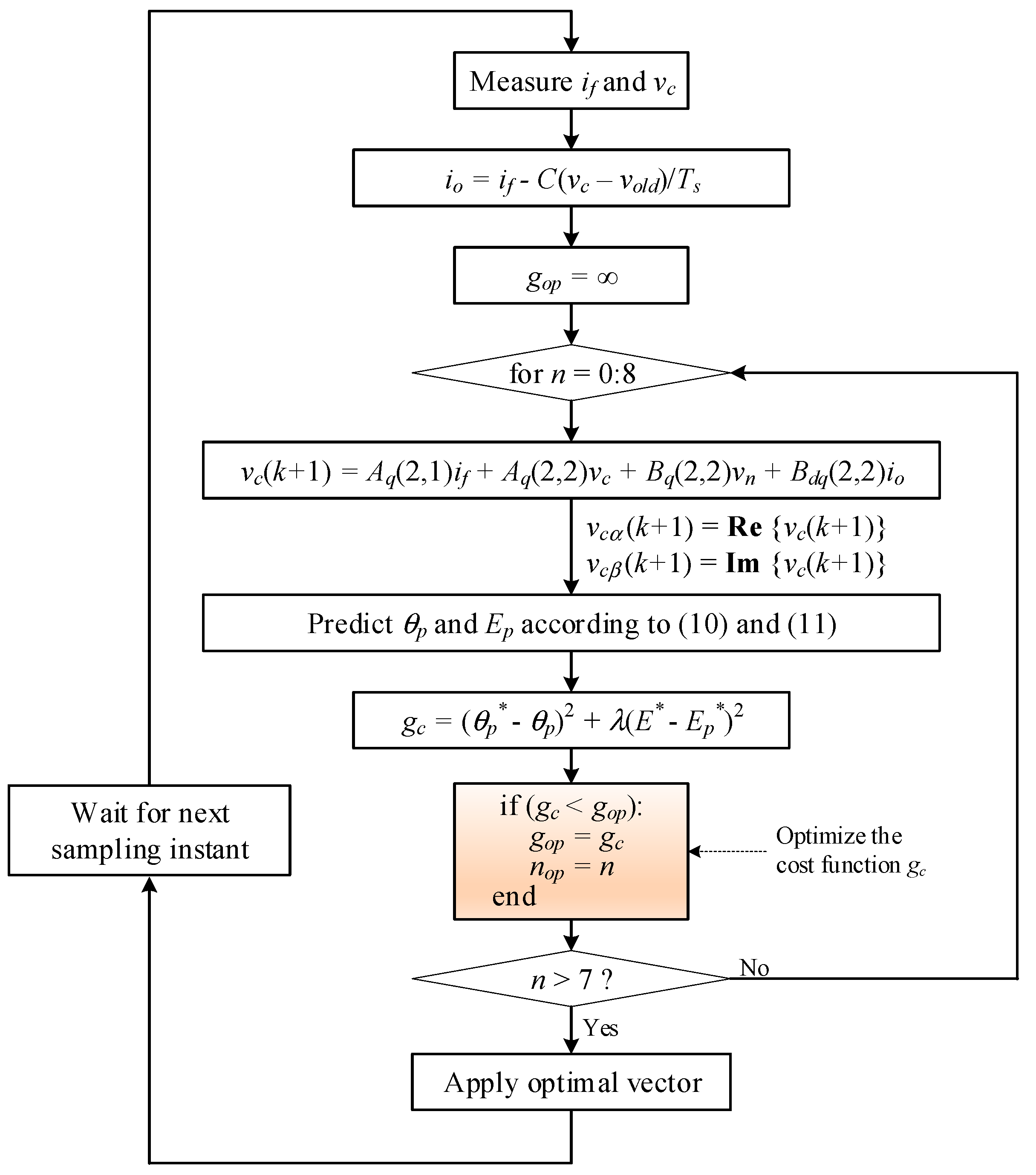
Once the phase angle and voltage amplitude are predicted, the optimal switching state that minimizes the error between the predicted and reference variables can be found by using the cost function gc in Equation (12).
where is the reference phase angle that corresponds to the reference frequency, E* is the reference voltage amplitude, and λ is the weighting factor. Since the phase angle and voltage amplitude should be controlled simultaneously with equal importance, the weighting factor λ is chosen as 1/Ebase in which Ebase is the base voltage of the MG system.
The flowchart of the proposed PAC algorithm is shown in Figure 6. The switching state that is expected to minimize the cost function Equation (12) is applied to the converter system.
4.2. Proposed PAC for an MG Application
Since the phase angle of the output voltage is directly controlled, the cost function of the PAC can be modified to operate the converter system in both the islanded and grid-connected modes. The flowchart of the proposed PAC algorithm for different operation modes of the MG system is shown in Figure 7.
In the islanded mode, the PAC for the grid-forming converter presented in Figure 6 is used to form the system frequency and voltage. The cost function gc can be used to find the optimal switching state. However, the cost function gc causes a steady-state error of the system voltage because the system performance between samples is not considered [33]. To solve the problem, the integral action is used in the cost function to reduce the steady-state error of voltage as given in Equation (13).
where is the measured voltage amplitude. The weighting factor λ is the same as in Equation (12).
When the operation mode of the MG system changes from the islanded to the grid-connected mode, the synchronization process is active. The phase angle of the grid voltage is calculated according to (10); then, it is compared with the phase angle of the MG system. The error between the two phase angles is estimated subsequently. If the error is in the allowable range, the STS is closed to connect the MG system to the grid. The process of synchronization is shown in Figure 7, in which the cost function is used to minimize the phase angle error of the grid voltage and MG voltage whereas the cost function is used to control constantly the power of the converter in the grid-connected mode. The cost functions and are given as follows.
where the is used to reduce the difference between the phase angle of the grid and the converter for the synchronization process.
where Δθ and ΔE are the compensated phase angle and voltage amplitude for power control, respectively.
When the MG system connects to the utility grid, the measured grid phase angle is used for the phase angle reference of the PAC. By compensating for the phase angle and voltage amplitude, the real and reactive powers can be controlled. The real and reactive power transfer (P and Q) from the converter to the MG bus is given in (16) and (17).
where Vc and V are the voltage amplitudes of the converter and bus voltage, respectively; R and X are the distribution line resistance and inductance, respectively; and δ is the different phase angle of the converter and bus voltages.
Since the impedance of the distribution line is mainly resistive (R >> X), the real power transfer mainly depends on the voltage amplitude while the reactive power transfer mainly depends on the phase angle. Based on this observation, the compensated phase angle and voltage amplitude for the power control in the grid-connected mode are given in Equations (18) and (19). The overall control diagram of the converter is shown in Figure 8.
where P* and Q* are the reference real and reactive powers, respectively; Pm and Qm are the measured real and reactive powers; and kp and ki are the parameters of the proportional-integral controller, respectively.
5. Simulation Results
A simple MG system shown in Figure 8 is considered to evaluate the performance of the proposed PAC, which consists of a converter-based distributed generation and a local load. The MG system connects to the utility grid by an STS. The system parameters are adopted from [40] as shown in Table 1.
5.1. Islanded Operation Mode
In the islanded operation mode, the functionality of the converter is the grid-forming converter that forms the system frequency and voltage. The performance of the proposed PAC in the islanded mode is shown in Figure 9, Figure 10 and Figure 11.
The real and reactive power supplied to the load from the converter is shown in Figure 9. The converter starts on the no load condition and the load connects to the MG system at 0.2 s. Additional load connects to the MG system at 1 s and disconnects at 1.5 s. It can be observed that the converter stably supplies power for the load change in the islanded operation mode.
The output voltage and current of the converter in the case of load change are shown in Figure 10 and Figure 11. The reference voltage amplitude is set to about 180 V and the system reference frequency is 60 Hz. It is shown that the output voltage and current are sinusoidal.
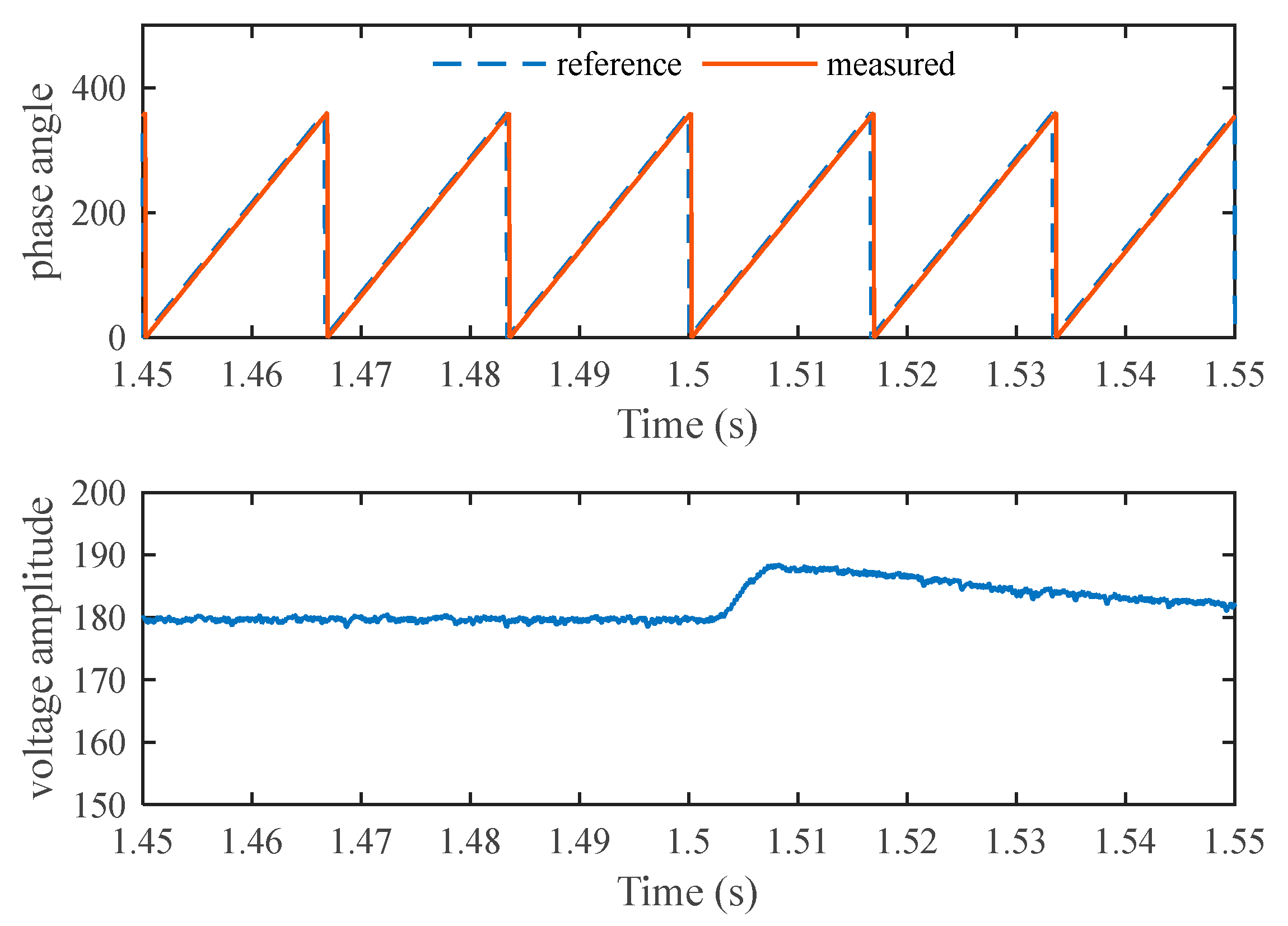
The behavior of the proposed PAC is shown in Figure 12 and Figure 13, in which the phase angle and voltage amplitude are shown. It is shown that the measured phase angle of the output voltage follows the reference phase angle closely. The transient exists in the voltage amplitude when the load is changed whereas it does not in the phase angle of the output voltage. Owing to the integral action in the cost function, there is no steady-state error in the output voltage amplitude. The output voltage changes rapidly after changing load; consequently, it gradually recovers to the reference value.
5.2. Synchronization Mode
The synchronization process is active when the converter receives the synchronization signal. The phase angle of the MG voltage is adjusted to be similar to the phase angle of the grid voltage. The performance of the proposed PAC in the grid synchronization mode is shown in Figure 14, Figure 15 and Figure 16.
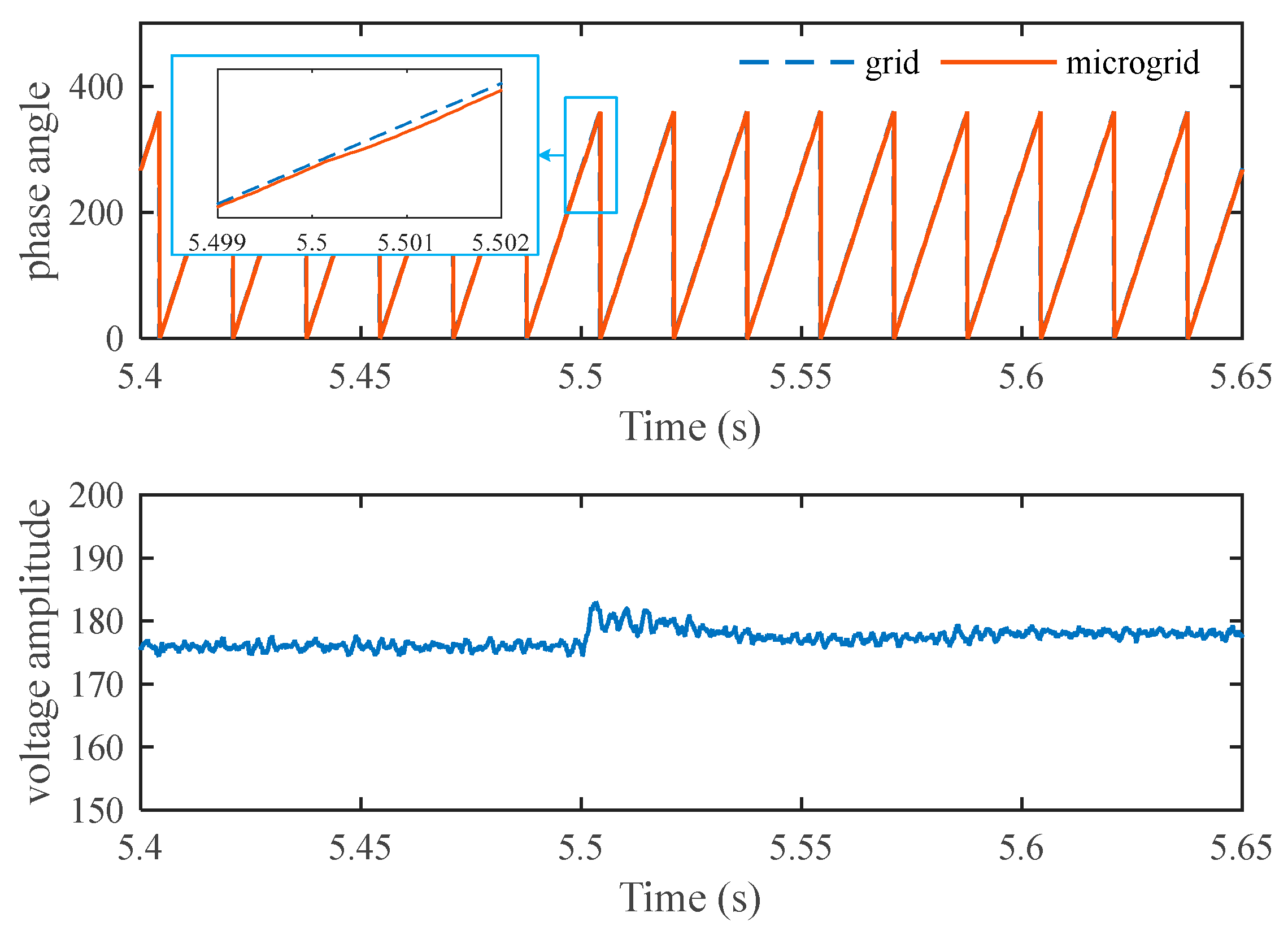
The converter receives the synchronization signal at 2 s and starts to adjust the phase angle of the output filter voltage. The MG voltage and grid voltage in one phase are shown in Figure 14. The phase angle of the MG voltage and the grid voltage is shown in Figure 15. It is shown that the PAC gradually changes the phase angle of the MG voltage to reduce the phase angle error between the MG voltage and the grid voltage. When the phase angle error is in the allowable range for synchronization, the closing signal is sent to the STS and the MG system connects to the grid at around 2.18 s. Once the MG system connects to the grid, the measured phase angle of the grid voltage is used as the reference for the converter. It is observed that the measured phase angle of the converter is tracked closely to the phase angle of the grid voltage after connecting to the grid and there is no transience in the phase angle in this operation mode.
The three-phase current and voltage of the converter during the transition mode from the islanded to the grid-connected mode are shown in Figure 16. It can be seen that a seamless transition is achieved with the proposed PAC. There is no transience in either the voltage or the current of the converter when the MG system connects to the grid. Under the steady-state condition, the voltage and current amplitudes are varied slightly because the functionality of the converter is changed to the grid-feeding converter. The real and reactive power of the converter during the transition mode is shown in Figure 17. When the MG system completely connects to the grid, the converter constantly supplies power in the amount of 5 kW and 0 kVAr.
5.3. Grid-Connected Operation Mode
When the STS is closed, the MG system is operated in the grid-connected operation mode where the converter plays the role of suppling constant power. The reference phase angle for the PAC is changed to the measured phase angle of the grid. Owing to the relationship of the real and reactive power with the phase angle and voltage amplitude, the PI regulator is used to control the power output by compensating for the phase angle and voltage amplitude.
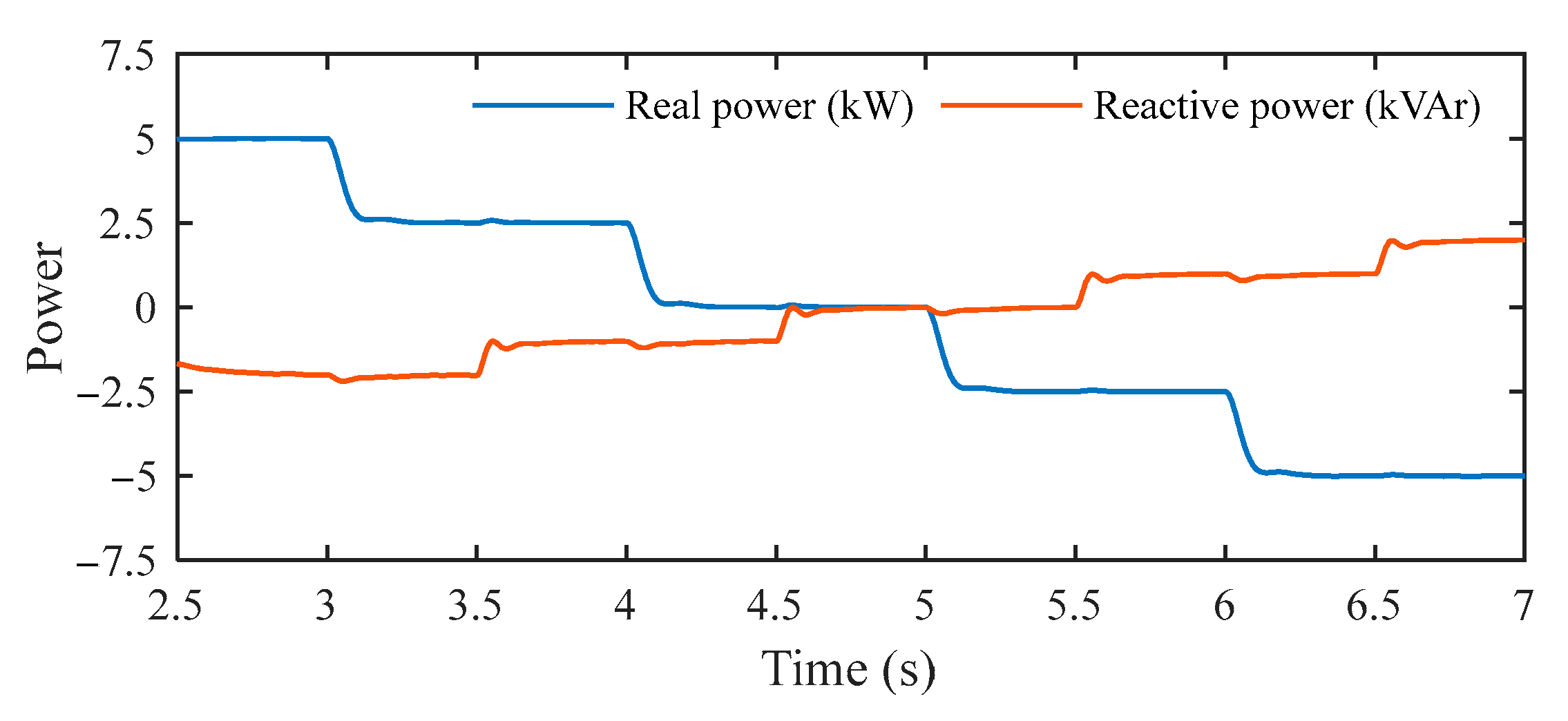
The control performance of PAC for power regulation in the grid-connected mode is shown in Figure 18. Several step changes of real and reactive power are carried out to test the control performance of the proposed PAC. At 4 s, the real power reference is set to −5 kW. It is shown that although the coupling of real and reactive power exists, the output power of the converter is well-controlled.
The phase angle and amplitude of output voltage of the converter when the real power is changed from +2.5 kW to 0 kW and the reactive power is changed from 0 kVAr to 1 kVAr are shown in Figure 19 and Figure 20, respectively. Negative real and reactive powers represent the charging of the ESSs in the MG system. Owing to the PI regulator of the power control loop, the voltage amplitude is changed to control the real power output of the converter and the phase angle is adjusted to control the reactive power output. Since the power converter constantly supplies or absorbs power, additional power is supplied from the utility grid as shown in Figure 21.
5.4. Comparison Study
In order to show the effectiveness of the proposed PAC method, a comparison study on the proposed method and the existing predictive control methods is carried out in this section. In the islanded operation mode, the proposed method is compared to the conventional predictive voltage control method presented in [42], whereas in the grid-connected mode, the proposed PAC is compared to the direct predictive power control method presented in [32].
With conventional predictive control, the controller of the converter changes according to the operation mode of the MG system. The predictive voltage control is used for islanded operation while predictive current or direct predictive power control is used for grid-connected operation. Figure 22 shows the waveforms of the output voltage and current with conventional predictive control when the operation mode is changed from islanded mode to grid-connected mode. Compared to Figure 16 where the proposed method is used, the waveforms of the output voltage and current in the case of the proposed method are better than the case of the conventional method. The change of inverter controller from predictive voltage control to direct predictive power control causes transience in the voltage and current as shown in Figure 22. In addition, the output power of the converter with conventional predictive control in the grid-connected mode is shown in Figure 23. The real and reactive power references are the same as that of the proposed PAC method (Figure 18). Although the real power is controlled well, there is steady-state error in the reactive power control. Since conventional direct predictive power control neglects the reactive power from the filter capacitor, the reactive power control is not correct. The direct predictive power control should be improved for the converter with an output LC filter.
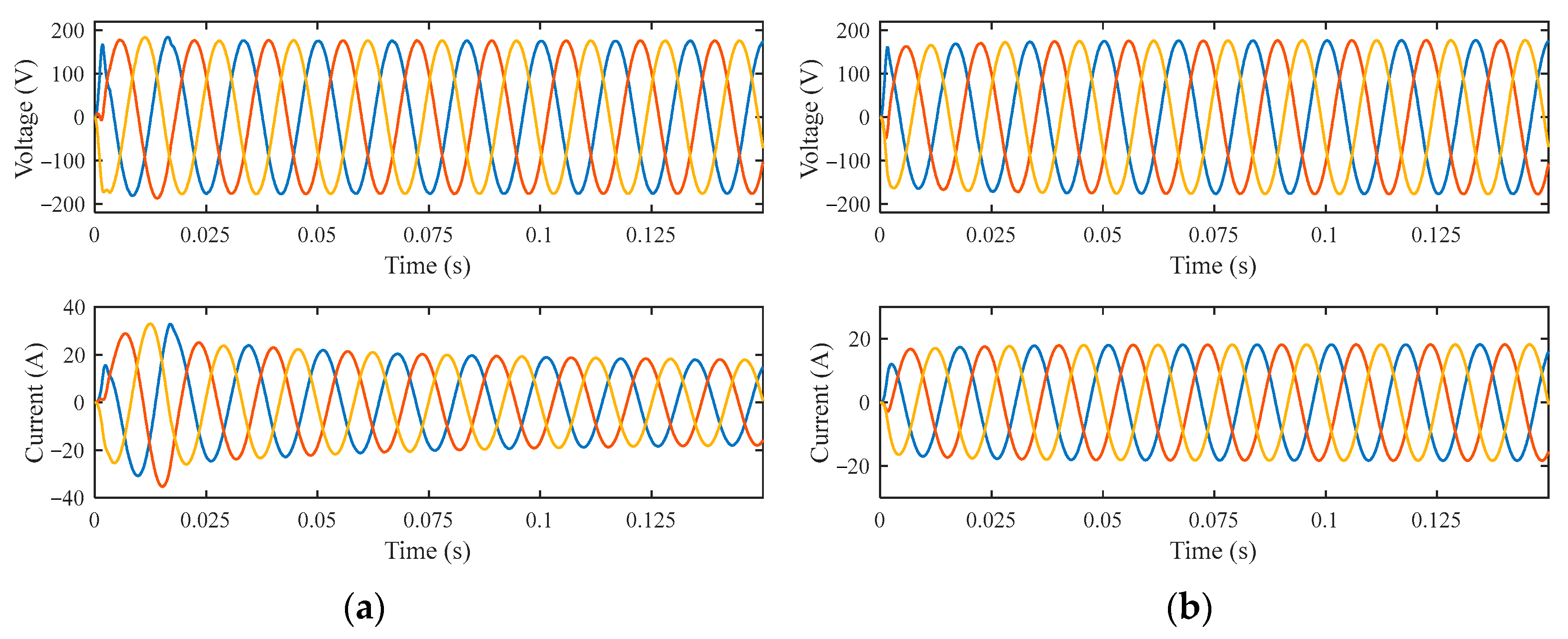
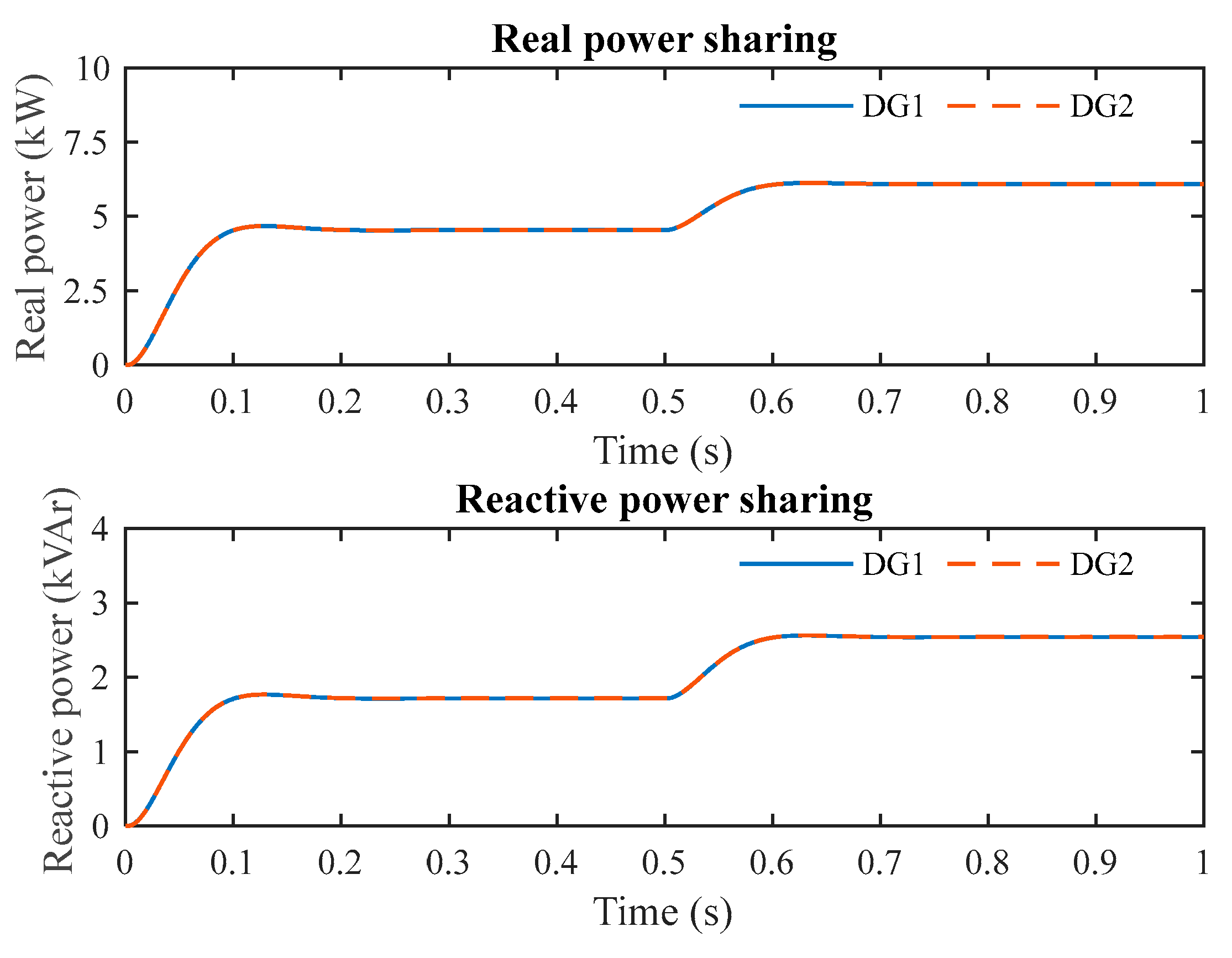
In the islanded operation mode, it is important to maintain accurate power sharing among multiple converters. An MG system with two converters is tested to show the effectiveness of the proposed method. Two converters with the same power rating are connected in parallel through a distribution line and supply to a common load. Figure 24 and Figure 25 show the real and reactive power sharing in the cases of conventional predictive voltage control and the proposed predictive method, respectively. In the case of conventional predictive control, initially, the real and reactive power are unequally shared and there is an overshoot of the real and reactive power of DG2. By comparison, the proposed predictive control method shows superior performance to the conventional method as shown in Figure 25. The real and reactive power are shared accurately and there is no significant overshoot in output power. The current and voltage waveforms of the two converters with the conventional and proposed predictive methods are shown in Figure 26 and Figure 27. It can be observed that the proposed predictive control method performs better than the conventional method.
6. Conclusions
This study proposed a new PAC for a power converter for use in both islanded and grid-connected operation modes, which directly regulates the phase angle and voltage amplitude of the output voltage. With the proposed PAC, the converter behavior was similar to the conventional synchronous generator in which the system frequency and voltage were controlled through the phase angle and the amplitude of output voltage. Additionally, the synchronization process could be easier due to the direct regulation of the phase angle. In both islanded and grid-connected operation modes, the main cost function did not change significantly, which results in a seamless transition between the MG’s operation modes. A comparison study on the proposed PAC method and existing predictive methods, namely predictive voltage control and direct predictive power control, was presented to show the effectiveness of the proposed method. It was observed that the proposed method could reduce the transience in the current when the operation mode is changed, maintain accurate real and reactive power sharing in islanded mode, and control the reactive power correctly in the grid-connected mode. With the ability of direct phase angle regulation, flexible constraints of system frequency could be considered in the cost function of the proposed PAC to improve the control performance of the MG system. In addition, the proposed PAC for power converters could be adopted easily for the virtual synchronous generator technique that mimics the transient characteristic of the synchronous generator, which is considered to be our future work.
Author Contributions
Theoretical analysis, modeling, and manuscript preparation, T.-T.N.; Simulation, H.-J.Y.; Verified the analytical methods, H.-M.K.; Manuscript revision, H.N.-D.
Funding
This research received no external funding.
Acknowledgments
This work was supported by the Incheon National University Research Grant in 2016.
Conflicts of Interest
The authors declare no conflict of interest.
Nomenclature
| Indices and Sets | |
| i | Index of voltage vector from 0 to 7 |
| k | Index of prediction step |
| Parameters | |
| Vdc | DC source voltage |
| Lf | Filter inductance |
| Cf | Filter capacitance |
| R | Line resistance |
| L | Line inductance |
| Variables | |
| Sx | Switching signals of converter |
| vi | Possible voltage vector |
| if | Filter current |
| io | Output current |
| vc | Output voltage |
| Ebase | Base voltage of the MG system |
| E* | Magnitude of voltage reference |
| θ* | Angle reference |
| Ep | Predicted amplitude of voltage |
| θp | Predicted angle |
| Em | Measured voltage amplitude |
| θcomp | Angle compensation for synchronization |
| ΔE | Compensated voltage amplitude for power control |
| Δθ | Compensated phase angle for power control |
| ξθ | Error of phase angle for synchronization |
| ξE | Error of voltage amplitude for synchronization |
| Vc | Voltage amplitude of the converter |
| V | Bus votlage |
| δ | Different phase angle of converter and bus votlge |
| kp | Proportional gain of the PI controller |
| ki | Integral gain of the PI controller |
| P* | Real power reference |
| Q* | Reactive power reference |
| Pm | Measured real power |
| Qm | Measured reactive power |
| λ | Weighting factor |
| Functions | |
| gc | Cost function of predictive phase angle and voltage amplitude control |
| g1 | Cost function for reducing steady-state error of voltage in islanded mode |
| g2 | Cost function for synchronization |
| g3 | Cost function for power control in grid-connected mode |
References
- Hamilton, J.; Negnevitsky, M.; Wang, X. Economics of Renewable Energy Integration and Energy Storage via Low Load Diesel Application. Energies 2018, 11, 1080. [Google Scholar] [CrossRef]
- Serban, E.; Serban, H. A Control Strategy for a Distributed Power Generation Microgrid Application with Voltage- and Current-Controlled Source Converter. IEEE Trans. Power Electron. 2010, 25, 2981–2992. [Google Scholar] [CrossRef]
- Xiao, H.; Luo, A.; Shuai, Z.; Jin, G.; Huang, Y. An Improved Control Method for Multiple Bidirectional Power Converters in Hybrid AC/DC Microgrid. IEEE Trans. Smart Grid 2016, 7, 340–347. [Google Scholar] [CrossRef]
- Rocabert, J.; Luna, A.; Blaabjerg, F.; Rodríguez, P. Control of Power Converters in AC Microgrids. IEEE Trans. Power Electron. 2012, 27, 4734–4749. [Google Scholar] [CrossRef]
- Wang, P.; Goel, L.; Liu, X.; Choo, F.H. Harmonizing AC and DC: A Hybrid AC/DC Future Grid Solution. IEEE Power Energy Mag. 2013, 11, 76–83. [Google Scholar] [CrossRef]
- Hosseinzadeh, M.; Salmasi, F.R. Power Management of an Isolated Hybrid AC/DC Micro-Grid with Fuzzy Control of Battery Banks. IET Renew. Power Gener. 2015, 9, 484–493. [Google Scholar] [CrossRef]
- Deng, W.; Pei, W.; Li, L. Active Stabilization Control of Multi-Terminal AC/DC Hybrid System Based on Flexible Low-Voltage DC Power Distribution. Energies 2018, 11, 502. [Google Scholar] [CrossRef]
- De Matos, J.G.; E Silva, F.S.F.; Ribeiro, L.A.d.S. Power Control in AC Isolated Microgrids With Renewable Energy Sources and Energy Storage Systems. IEEE Trans. Ind. Electron. 2015, 62, 3490–3498. [Google Scholar]
- Nguyen, C.-K.; Nguyen, T.-T.; Yoo, H.-J.; Kim, H.-M. Improving Transient Response of Power Converter in a Stand-Alone Microgrid Using Virtual Synchronous Generator. Energies 2018, 11, 27. [Google Scholar] [CrossRef]
- Loh, P.C.; Li, D.; Chai, Y.K.; Blaabjerg, F. Autonomous Control of Interlinking Converter with Energy Storage in Hybrid AC–DC Microgrid. IEEE Trans. Ind. Appl. 2013, 49, 1374–1382. [Google Scholar] [CrossRef]
- Kant, K.; Jain, C.; Singh, B. A Hybrid Diesel-Wind PV-Based Energy Generation System with Brushless Generators. IEEE Trans. Ind. Inform. 2017, 13, 1714–1722. [Google Scholar] [CrossRef]
- Vasquez, J.C.; Guerrero, J.M.; Luna, A.; Rodriguez, P.; Teodorescu, R. Adaptive Droop Control Applied to Voltage-Source Inverters Operating in Grid-Connected and Islanded Modes. IEEE Trans. Ind. Electron. 2009, 56, 4088–4096. [Google Scholar] [CrossRef]
- Bui, V.-H.; Hussain, A.; Kim, H.-M. Optimal Operation of Microgrids Considering Auto-Configuration Function Using Multiagent System. Energies 2017, 10, 1484. [Google Scholar] [CrossRef]
- Ou, T.C.; Hong, C.M. Dynamic operation and control of microgrid hybrid power systems. Energy 2014, 66, 314–323. [Google Scholar] [CrossRef]
- Shafiee, Q.; Guerrero, J.M.; Vasquez, J.C. Distributed Secondary Control for Islanded Microgrids—A Novel Approach. IEEE Trans. Power Electron. 2014, 29, 1018–1031. [Google Scholar] [CrossRef] [Green Version]
- Ou, T.C. A novel unsymmetrical faults analysis for microgrid distribution systems. Int. J. Electr. Power. Energy Syst. 2012, 43, 1017–1024. [Google Scholar] [CrossRef]
- Ou, T.C. Ground fault current analysis with a direct building algorithm for microgrid distribution. Int. J. Electr. Power. Energy Syst. 2013, 53, 867–875. [Google Scholar] [CrossRef]
- Jin, L.; Kumar, R.; Elia, N. Model Predictive Control-Based Real-Time Power System Protection Schemes. IEEE Trans. Power Sys. 2010, 25, 988–998. [Google Scholar] [CrossRef] [Green Version]
- Ou, T.C.; Lu, K.H.; Huang, C.J. Improvement of transient stability in a hybrid power multi-system using a designed NIDC (Novel Intelligent Damping Controller). Energies 2017, 10, 488. [Google Scholar] [CrossRef]
- Yoo, H.-J.; Nguyen, T.-T.; Kim, H.-M. Multi-Frequency Control in a Stand-Alone Multi-Microgrid System Using a Back-To-Back Converter. Energies 2017, 10, 822. [Google Scholar] [CrossRef]
- Xia, Y.; Peng, Y.; Yang, P.; Yu, M.; Wei, W. Distributed Coordination Control for Multiple Bidirectional Power Converters in a Hybrid AC/DC Microgrid. IEEE Trans. Power Electron. 2017, 32, 4949–4959. [Google Scholar] [CrossRef]
- Hosseinzadeh, M.; Salmasi, F.R. Fault-Tolerant Supervisory Controller for a Hybrid AC/DC Micro-Grid. IEEE Trans. Smart Grid 2018, 9, 2809–2823. [Google Scholar] [CrossRef]
- Hosseinzadeh, M.; Salmasi, F.R. Robust Optimal Power Management System for a Hybrid AC/DC Micro-Grid. IEEE Trans. Sustain. Energy 2015, 6, 675–687. [Google Scholar] [CrossRef]
- Schonbergerschonberger, J.; Duke, R.; Round, S.D. DC-Bus Signaling: A Distributed Control Strategy for a Hybrid Renewable Nanogrid. IEEE Trans. Ind. Electron. 2006, 53, 1453–1460. [Google Scholar] [CrossRef] [Green Version]
- Malik, S.M.; Ai, X.; Sun, Y.; Zhengqi, C.; Shupeng, Z. Voltage and frequency control strategies of hybrid AC/DC microgrid: A review. IET Gener. Transm. Distrib. 2017, 11, 303–313. [Google Scholar] [CrossRef]
- Kim, J.-Y.; Kim, H.-M.; Kim, S.-K.; Jeon, J.-H.; Choi, H.-K. Designing an Energy Storage System Fuzzy PID Controller for Microgrid Islanded Operation. Energies 2011, 4, 1443–1460. [Google Scholar] [CrossRef] [Green Version]
- Baghaee, H.R.; Mirsalim, M.; Gharehpetian, G.B. Performance Improvement of Multi-DER Microgrid for Small- and Large-Signal Disturbances and Nonlinear Loads: Novel Complementary Control Loop and Fuzzy Controller in a Hierarchical Droop-Based Control Scheme. IEEE Syst. J 2018. Accepted for publication. [Google Scholar] [CrossRef]
- Nguyen, T.T.; Yoo, H.J.; Kim, H.M. Applying Model Predictive Control to SMES System in Microgrids for Eddy Current Losses Reduction. IEEE Trans. Appl. Supercond. 2016, 26, 1–5. [Google Scholar] [CrossRef]
- Nguyen, T.-T.; Yoo, H.-J.; Kim, H.-M. Application of Model Predictive Control to BESS for Microgrid Control. Energies 2015, 8, 8798–8813. [Google Scholar] [CrossRef] [Green Version]
- Wang, Y.; Chen, Z.; Wang, X.; Tian, Y.; Tan, Y.; Yang, C. An Estimator-Based Distributed Voltage-Predictive Control Strategy for AC Islanded Microgrids. IEEE Trans. Power Electron. 2015, 30, 3934–3951. [Google Scholar] [CrossRef]
- Dragičević, T. Model Predictive Control of Power Converters for Robust and Fast Operation of AC Microgrids. IEEE Trans. Power Electron. 2018. Accepted for publication. [Google Scholar] [CrossRef]
- Rodriguez, J.; Cortes, P. Predictive Control of Power Converters and Electrical Drives, 1st ed.; Wiley-IEEE Press: Chichester, UK, 2012. [Google Scholar]
- Stellato, B.; Geyer, T.; Goulart, P.J. High-Speed Finite Control Set Model Predictive Control for Power Electronics. IEEE Trans. Power Electron. 2017, 32, 4007–4020. [Google Scholar] [CrossRef] [Green Version]
- Panten, N.; Hoffmann, N.; Fuchs, F.W. Finite Control Set Model Predictive Current Control for Grid-Connected Voltage-Source Converters with LCL Filters: A Study Based on Different State Feedbacks. IEEE Trans. Power Electron. 2016, 31, 5189–5200. [Google Scholar] [CrossRef]
- Shadmand, M.B.; Balog, R.S.; Abu-Rub, H. Model Predictive Control of PV Sources in a Smart DC Distribution System: Maximum Power Point Tracking and Droop Control. IEEE Trans. Energy Convers. 2014, 29, 913–921. [Google Scholar] [CrossRef]
- Rohten, J.A.; Espinoza, J.R.; Muñoz, J.A.; Pérez, M.A.; Melin, P.E.; Silva, J.J.; Espinosa, E.E.; Rivera, M.E. Model Predictive Control for Power Converters in a Distorted Three-Phase Power Supply. IEEE Trans. Ind. Electron. 2016, 63, 5838–5848. [Google Scholar] [CrossRef]
- Jin, N.; Hu, S.; Gan, C.; Ling, Z. Finite States Model Predictive Control for Fault Tolerant Operation of Three-Phase Bidirectional AC/DC Converter Under Unbalanced Grid Voltages. IEEE Trans. Ind. Electron. 2018. Accepted for publication. [Google Scholar] [CrossRef]
- Tavakoli, A.; Negnevitsky, M.; Muttaqi, K.M. A Decentralized Model Predictive Control for Operation of Multiple Distributed Generators in an Islanded Mode. IEEE Trans. Ind. Appl. 2017, 53, 1466–1475. [Google Scholar] [CrossRef]
- Lou, G.; Gu, W.; Xu, Y.; Cheng, M.; Liu, W. Distributed MPC-Based Secondary Voltage Control Scheme for Autonomous Droop-Controlled Microgrids. IEEE Trans. Sustain. Energy 2017, 8, 792–804. [Google Scholar] [CrossRef]
- Han, J.; Solanki, S.K.; Solanki, J. Coordinated Predictive Control of a Wind/Battery Microgrid System. IEEE Trans. Emerg. Sel. Top. Power Electron. 2013, 1, 296–305. [Google Scholar] [CrossRef]
- Babqi, A.J.; Etemadi, A.H. MPC-based microgrid control with supplementary fault current limitation and smooth transition mechanisms. IET Gener. Transm. Distrib. 2017, 11, 2164–2172. [Google Scholar] [CrossRef]
- Cortes, P.; Ortiz, G.; Yuz, J.I.; Rodriguez, J.; Vazquez, S.; Franquelo, L.G. Model Predictive Control of an Inverter with Output LC Filter for UPS Applications. IEEE Trans. Ind. Electron. 2009, 56, 1875–1883. [Google Scholar] [CrossRef]
Figure 1.
Inverter-based distributed generations in a microgrid. STS, static transfer switch.
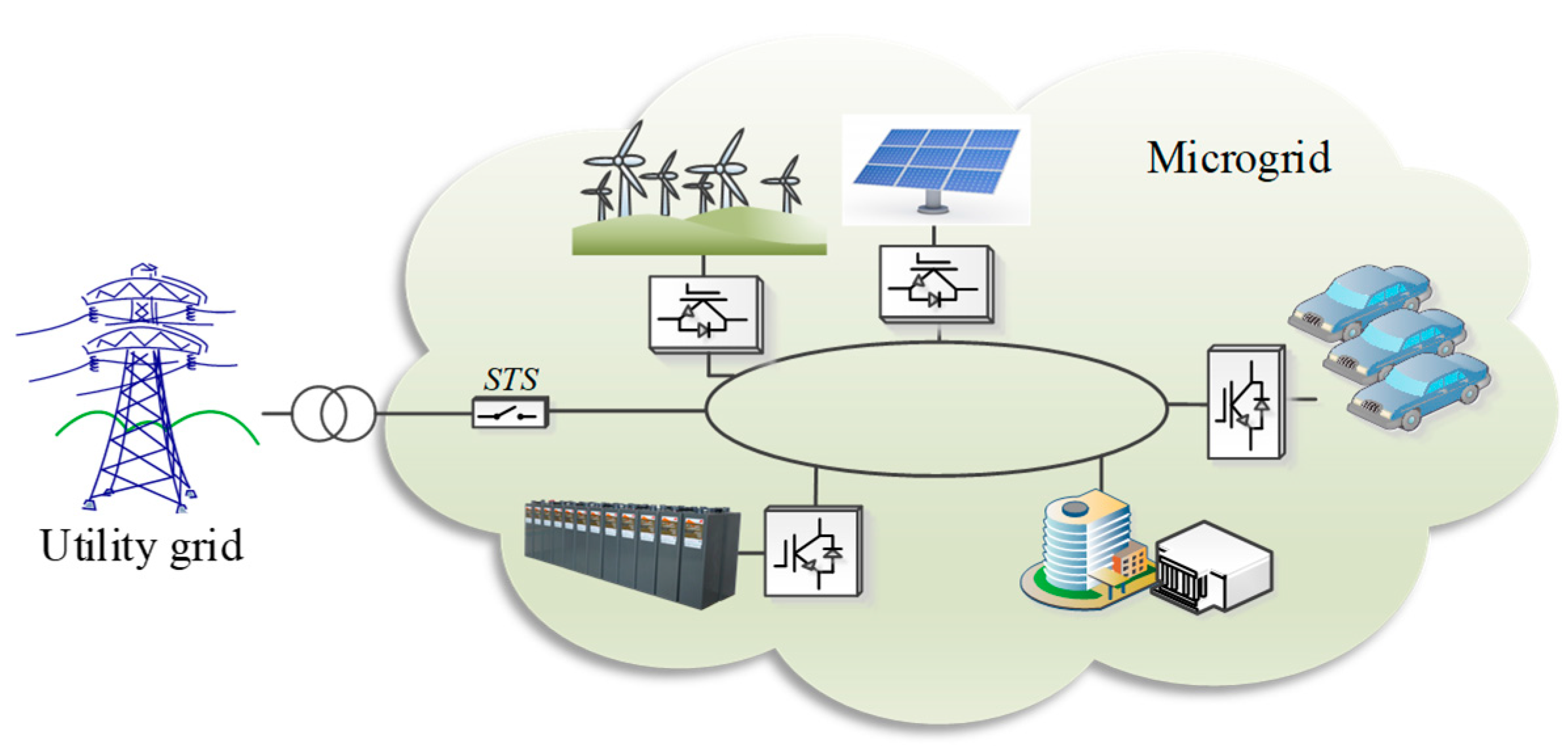
Figure 2.
Three-phase converter with output LC filter. AC, alternating current.
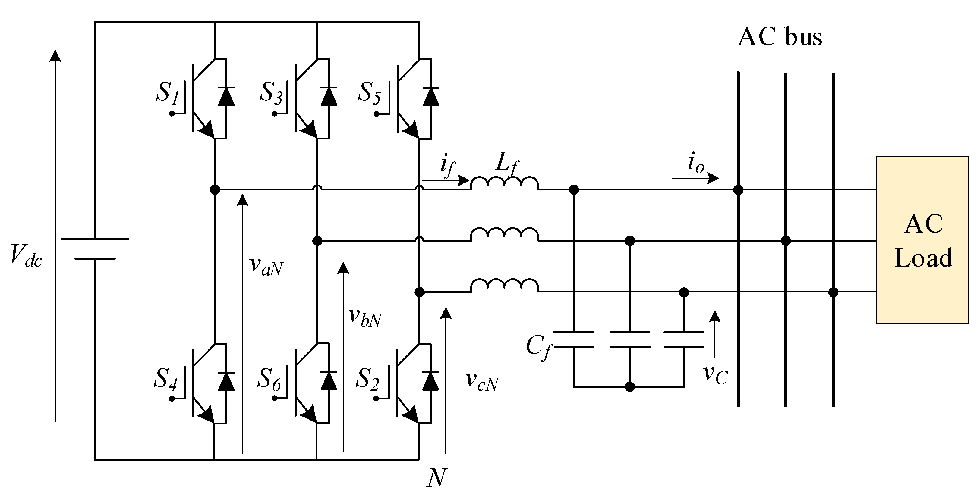
Figure 3.
Possibilities of voltage vectors in the converter.
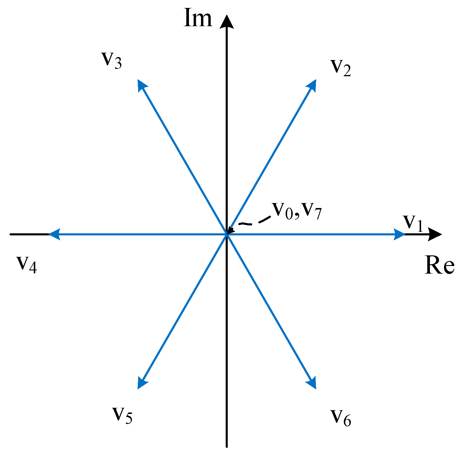
Figure 4.
Block diagram of predictive voltage control (PVC) for the grid-forming converter.
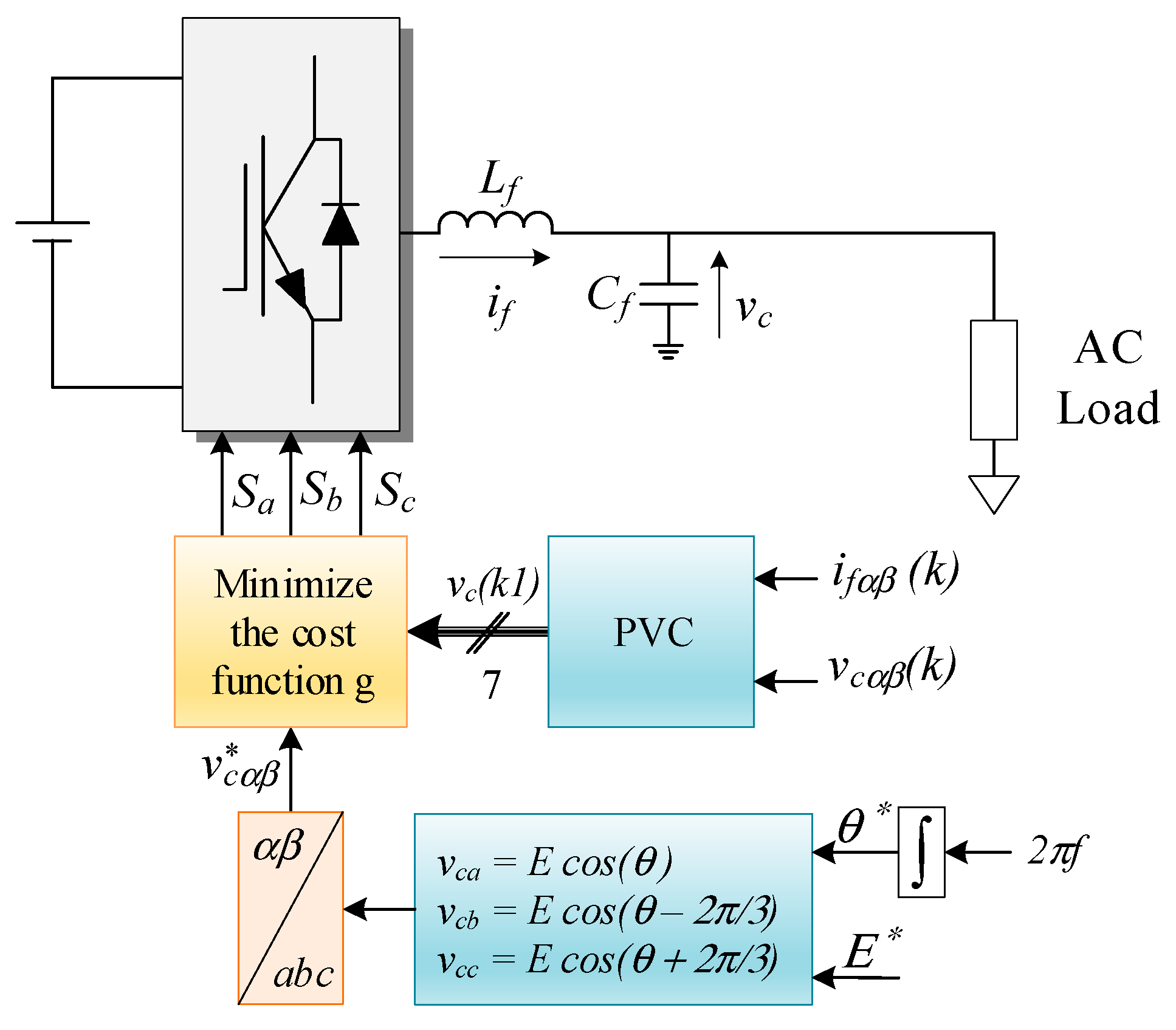
Figure 5.
Predictive phase angle and amplitude of voltage vectors.
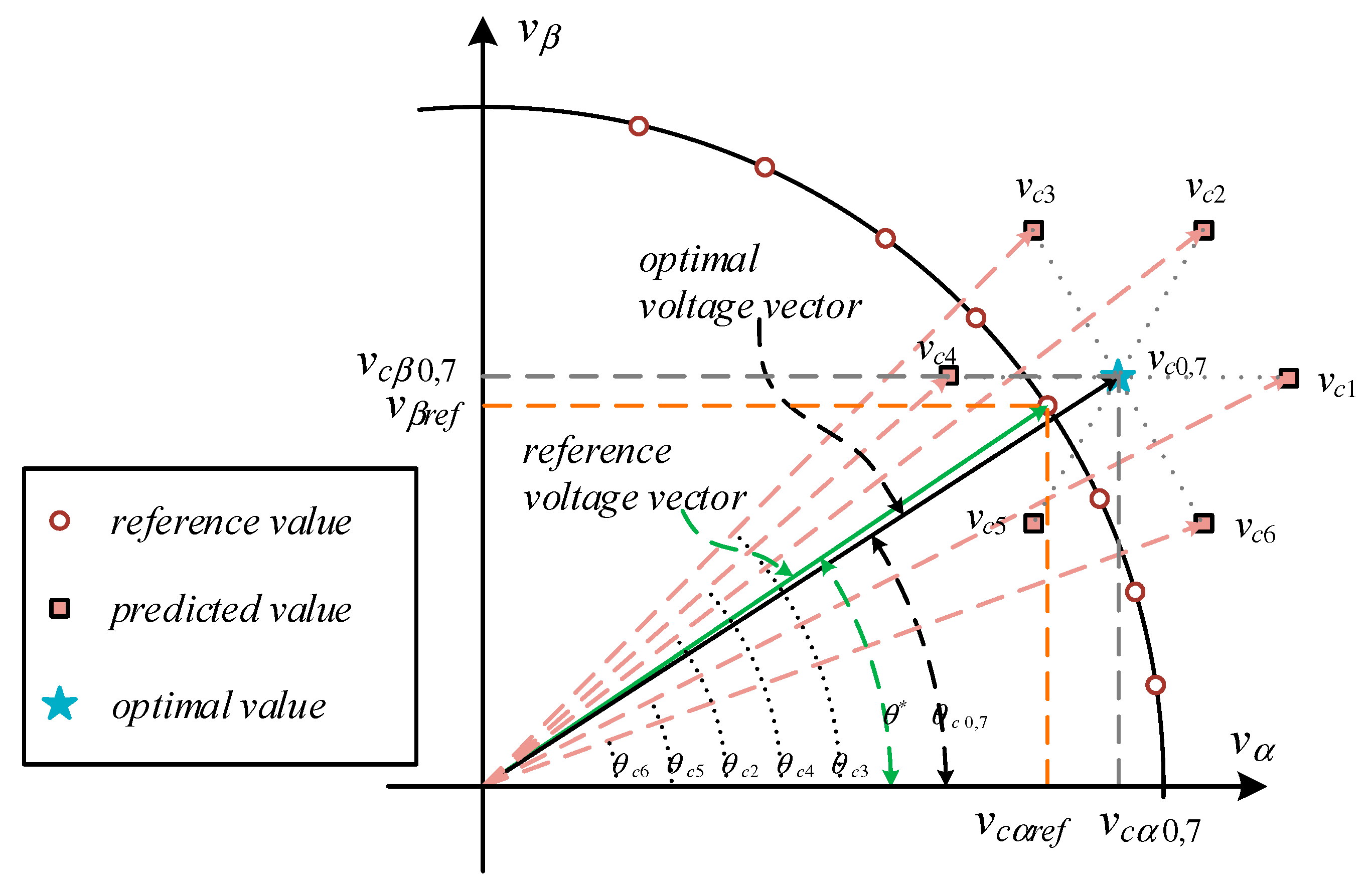
Figure 6.
Flowchart of the direct phase angle and voltage amplitude model predictive control (PAC) algorithm for the grid-forming converter.
Figure 6.
Flowchart of the direct phase angle and voltage amplitude model predictive control (PAC) algorithm for the grid-forming converter.

Figure 7.
Flowchart of the PAC algorithm for different operation modes of the microgrid (MG) system.
Figure 7.
Flowchart of the PAC algorithm for different operation modes of the microgrid (MG) system.
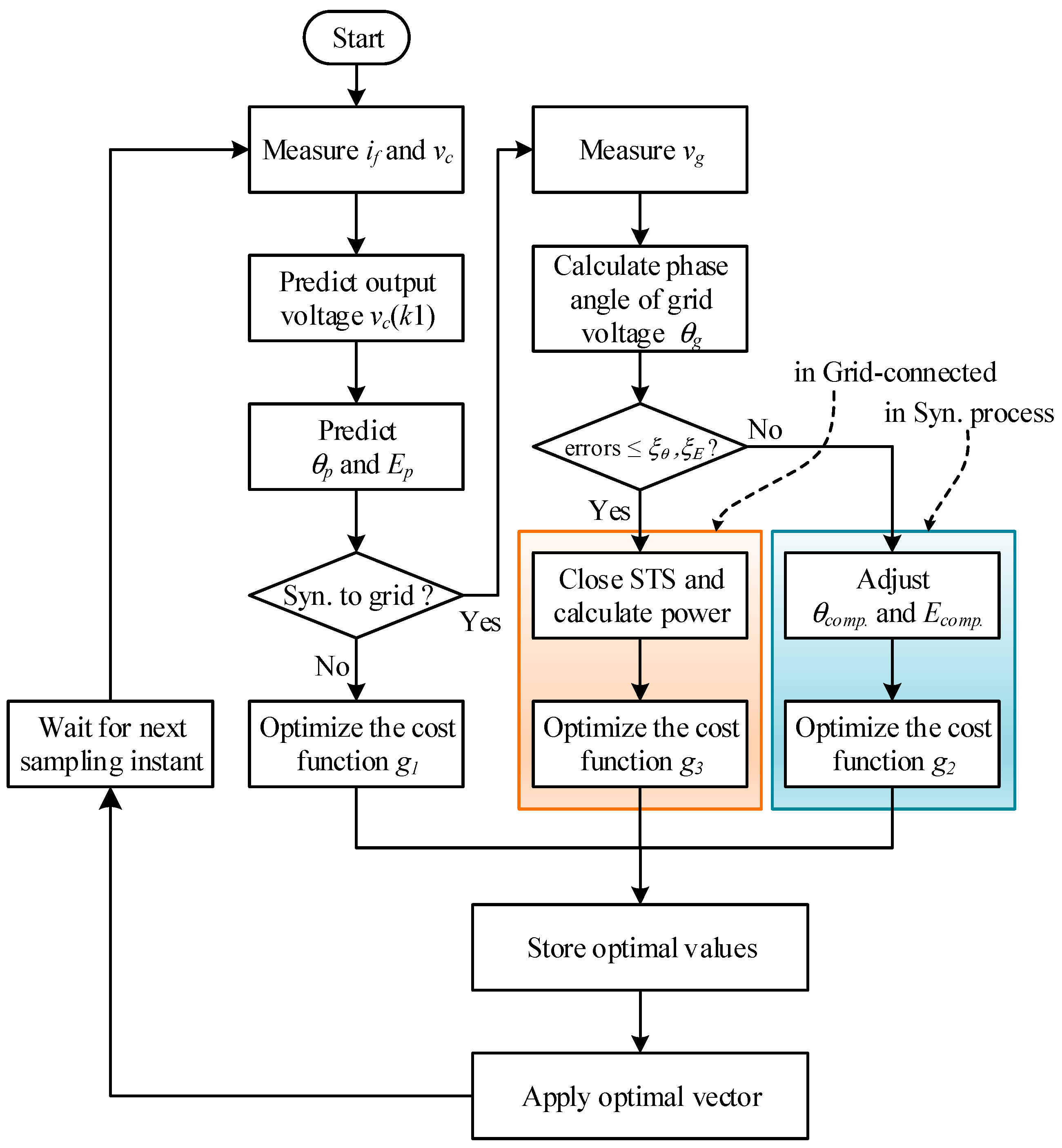
Figure 8.
Block diagram of the PAC for the MG application.
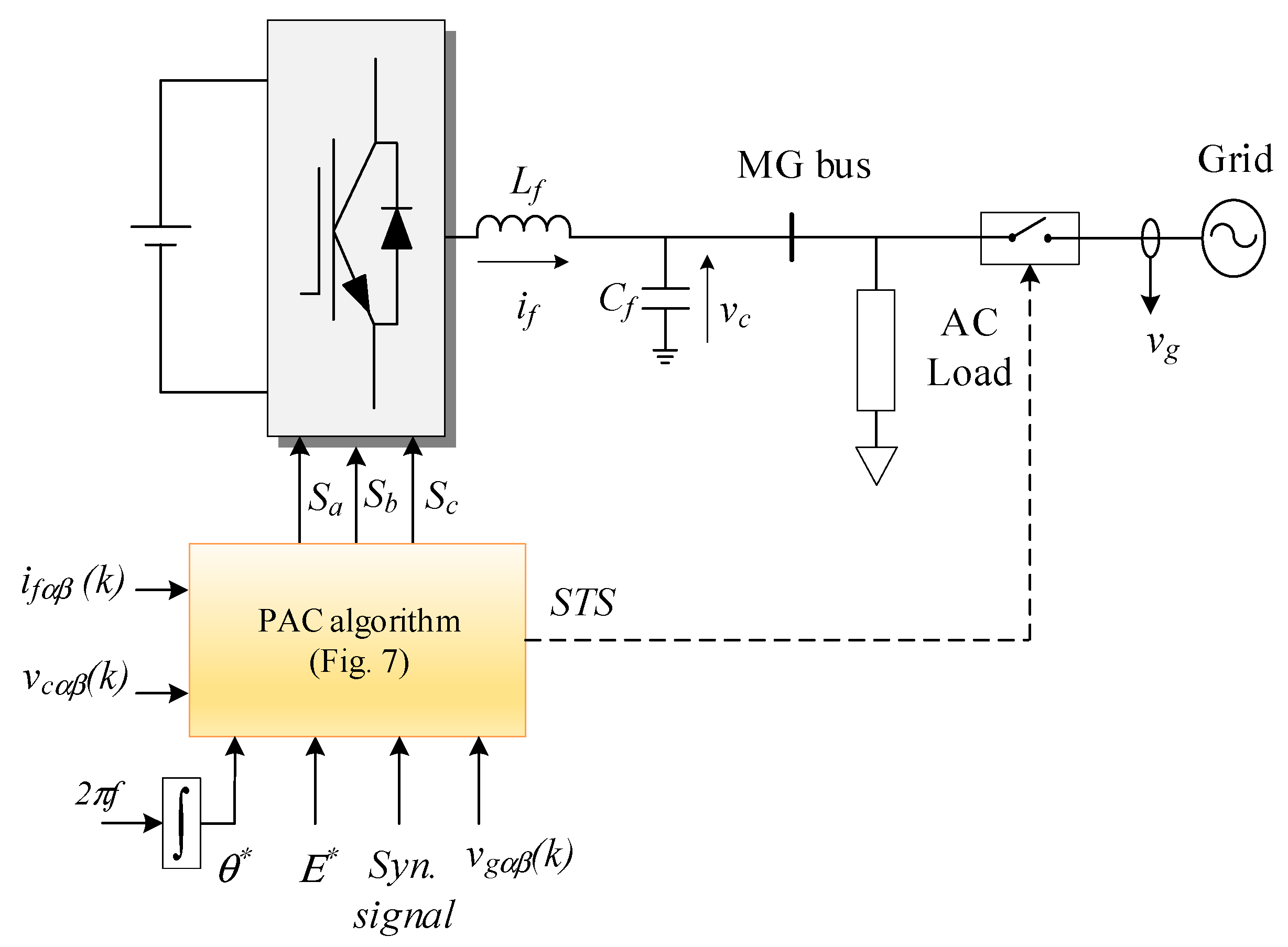
Figure 9.
Power supply from the converter for load step from no load.
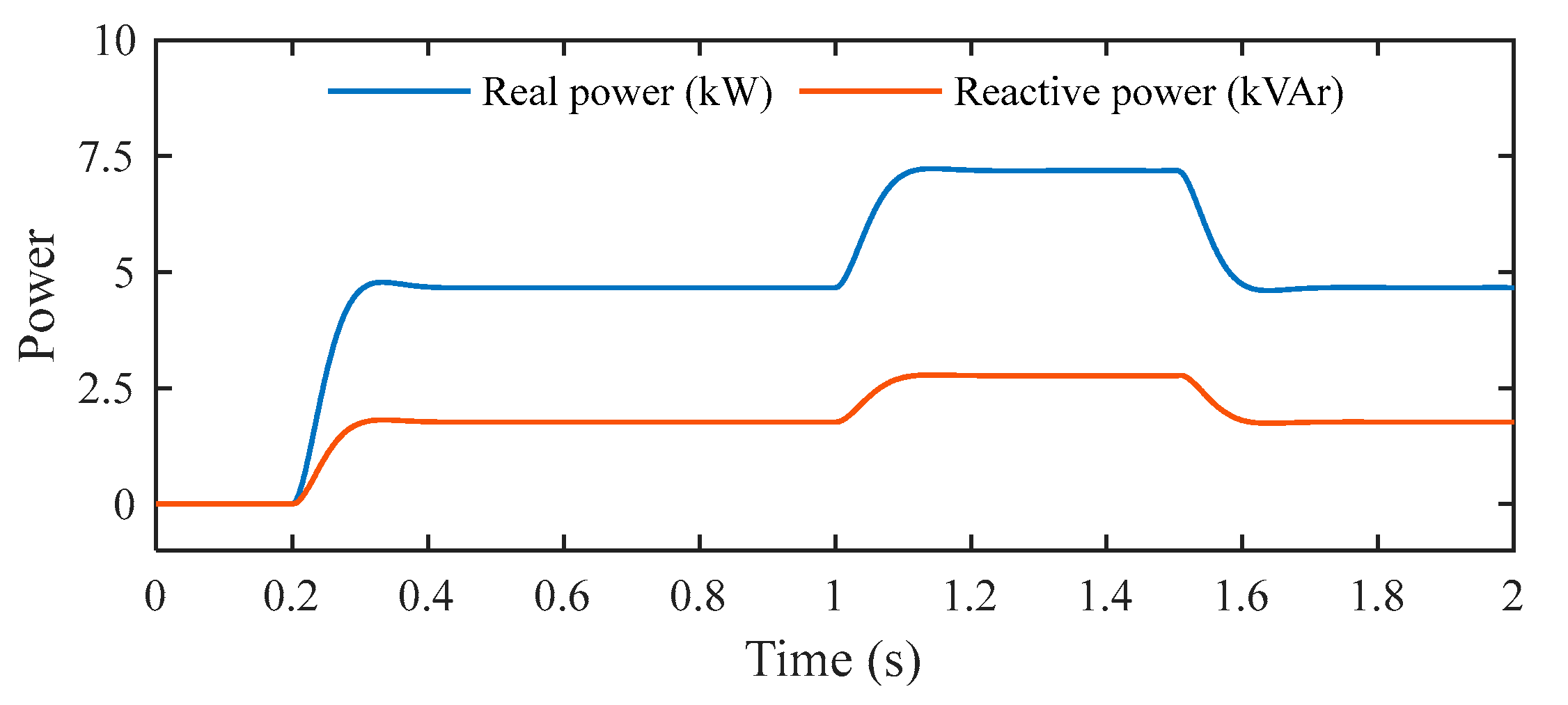
Figure 10.
Output voltage and output current for load step from no load.
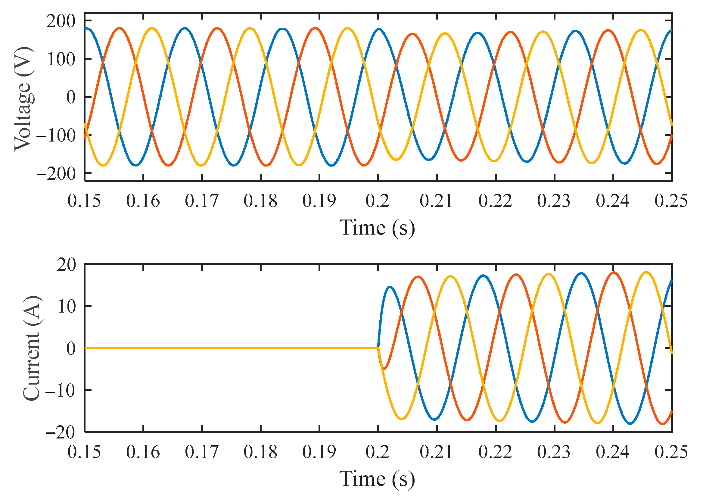
Figure 11.
Output voltage and output current for load reduction.

Figure 12.
Phase angle and voltage amplitude when the load is changed from a no load condition.

Figure 13.
Phase angle and voltage amplitude when a load is disconnected.

Figure 14.
MG and grid voltage in one phase.
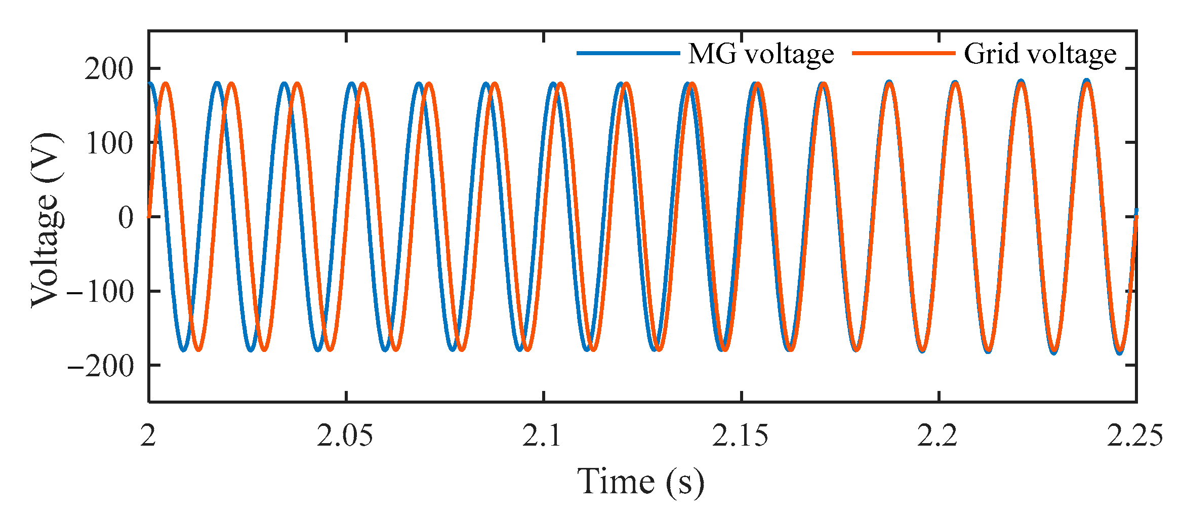
Figure 15.
Phase angle and voltage amplitude during transition mode.
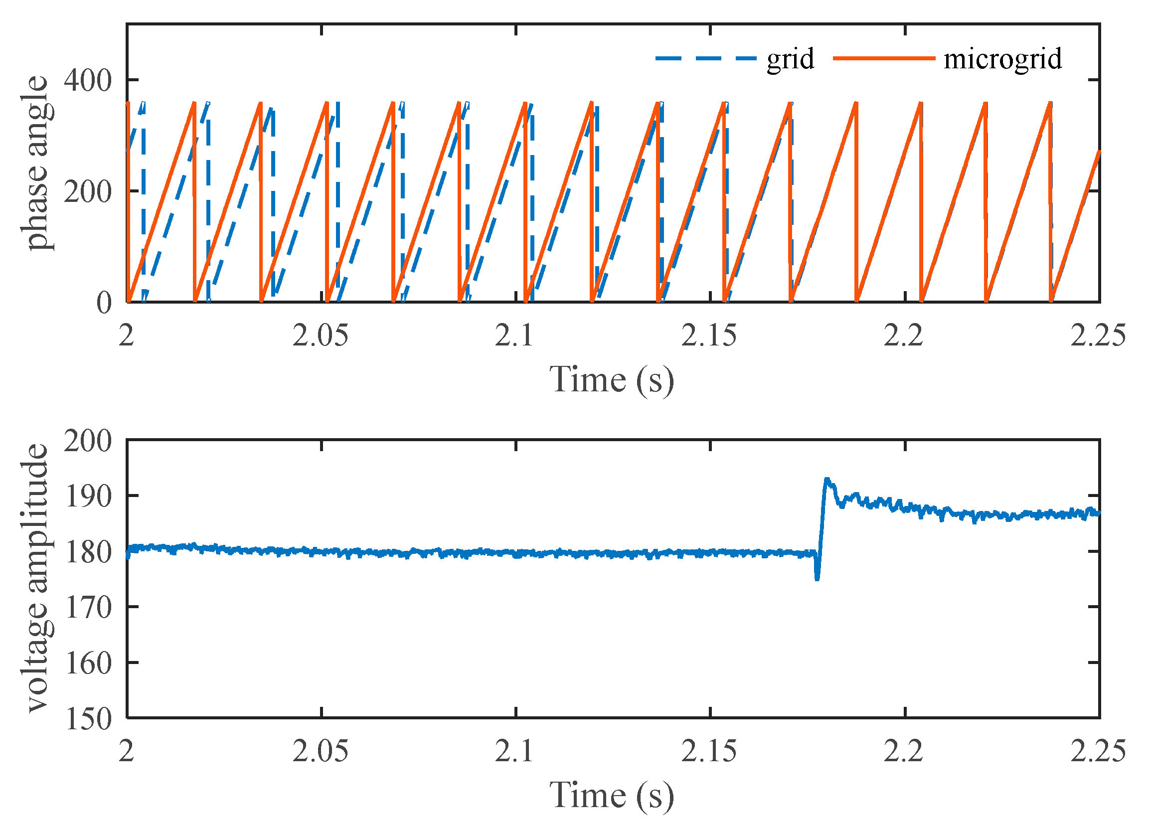
Figure 16.
Three-phase output voltage and current during transition mode.
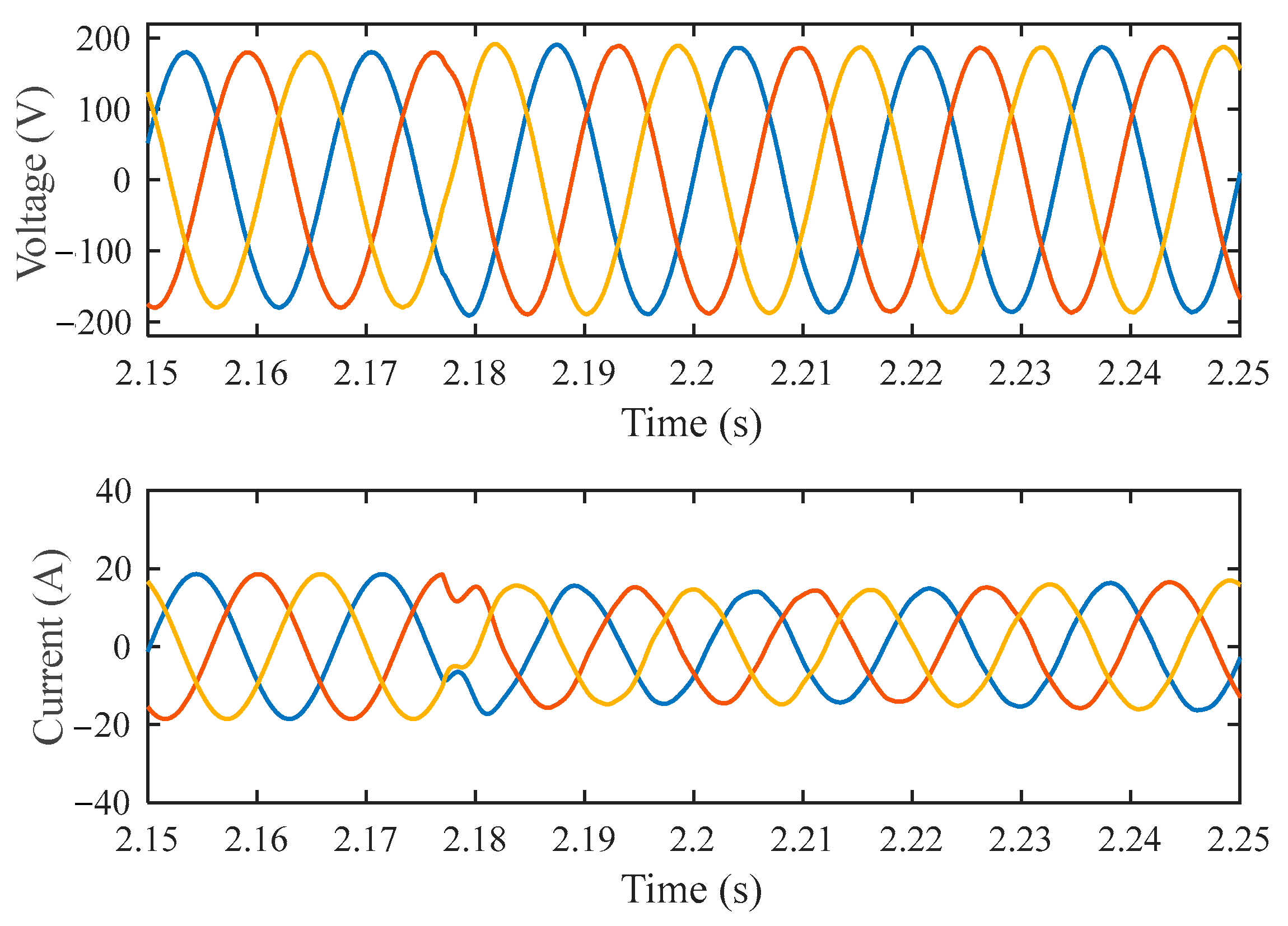
Figure 17.
Output real and reactive power of the converter when the MG connects to the grid.
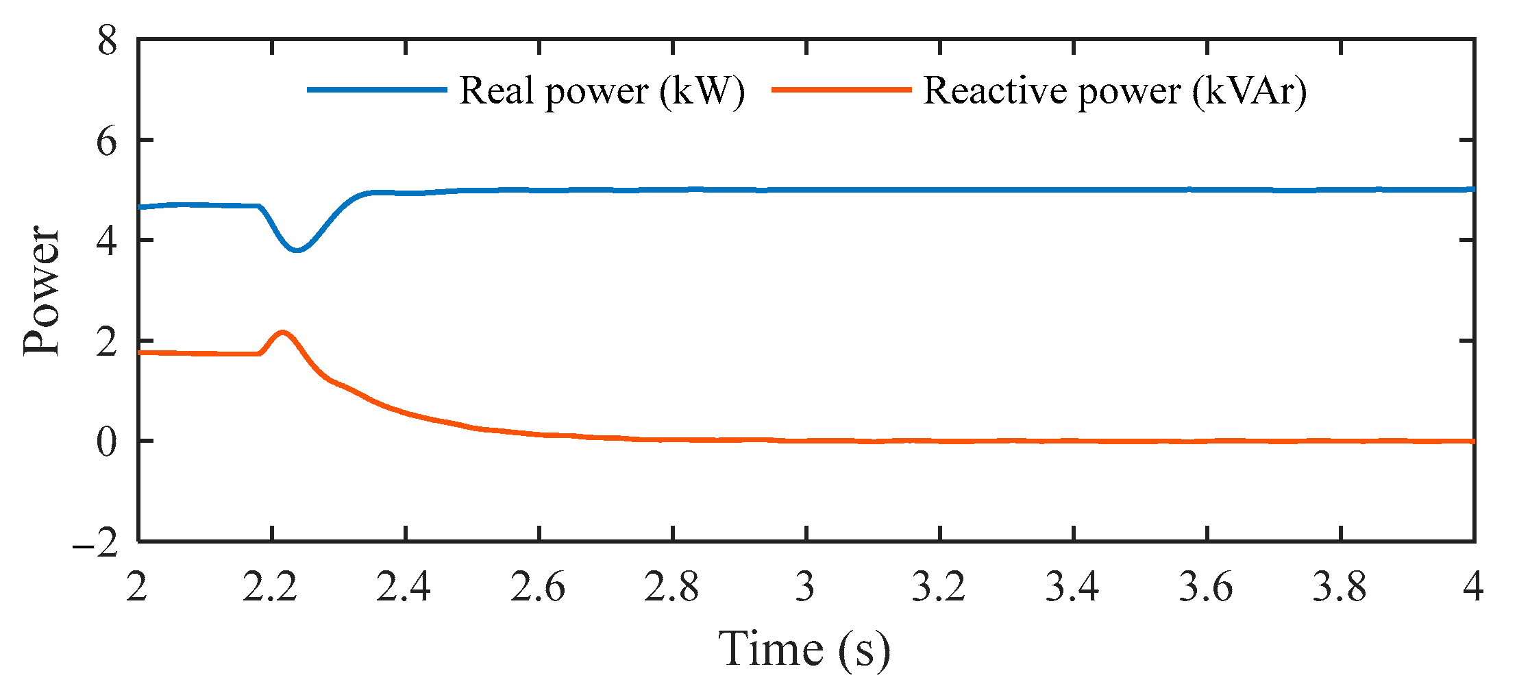
Figure 18.
Output power of converter.

Figure 19.
Phase angle and amplitude of output voltage.
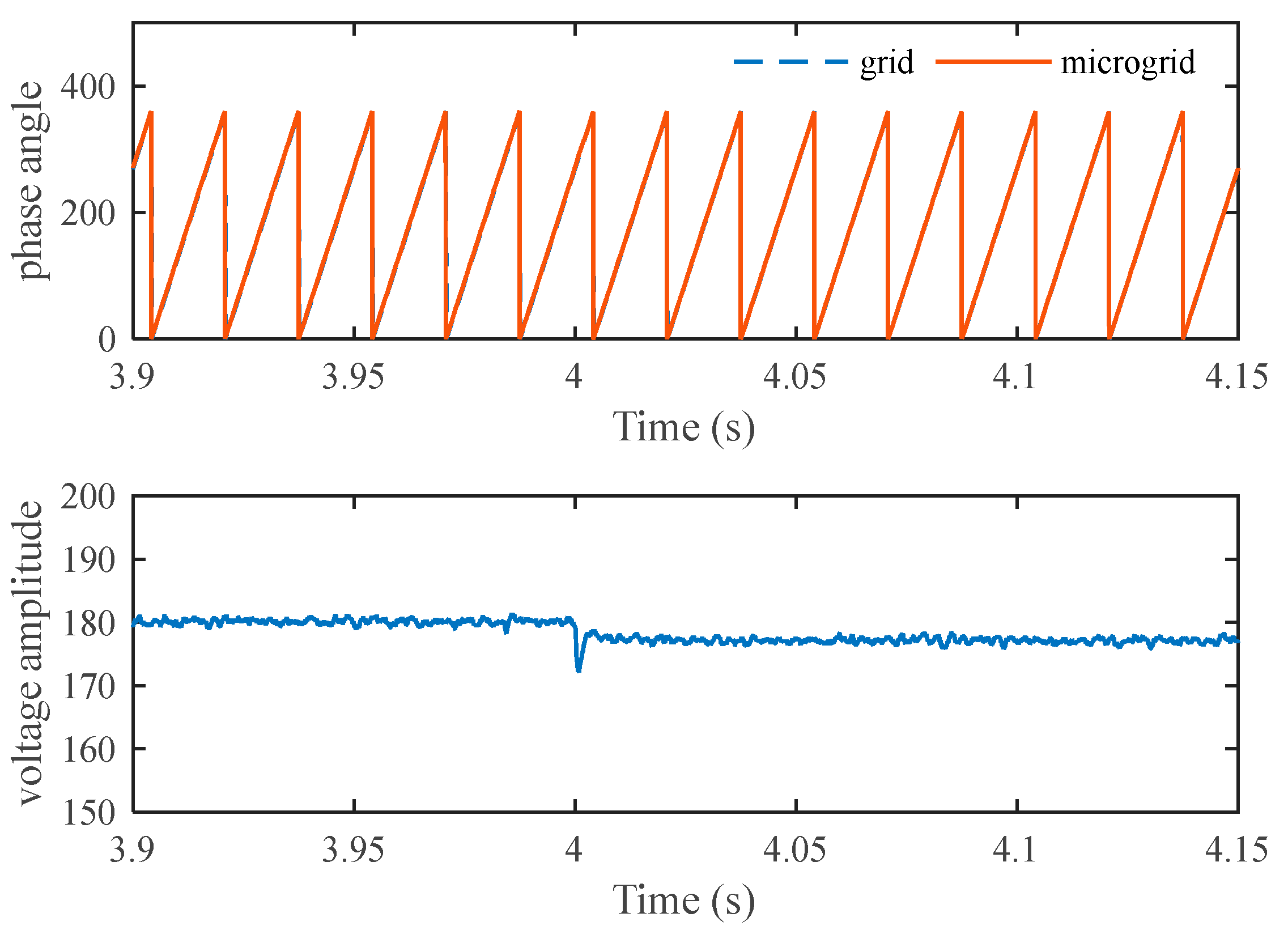
Figure 20.
Three-phase output voltage and current of the converter.

Figure 21.
Exchange power with grid.
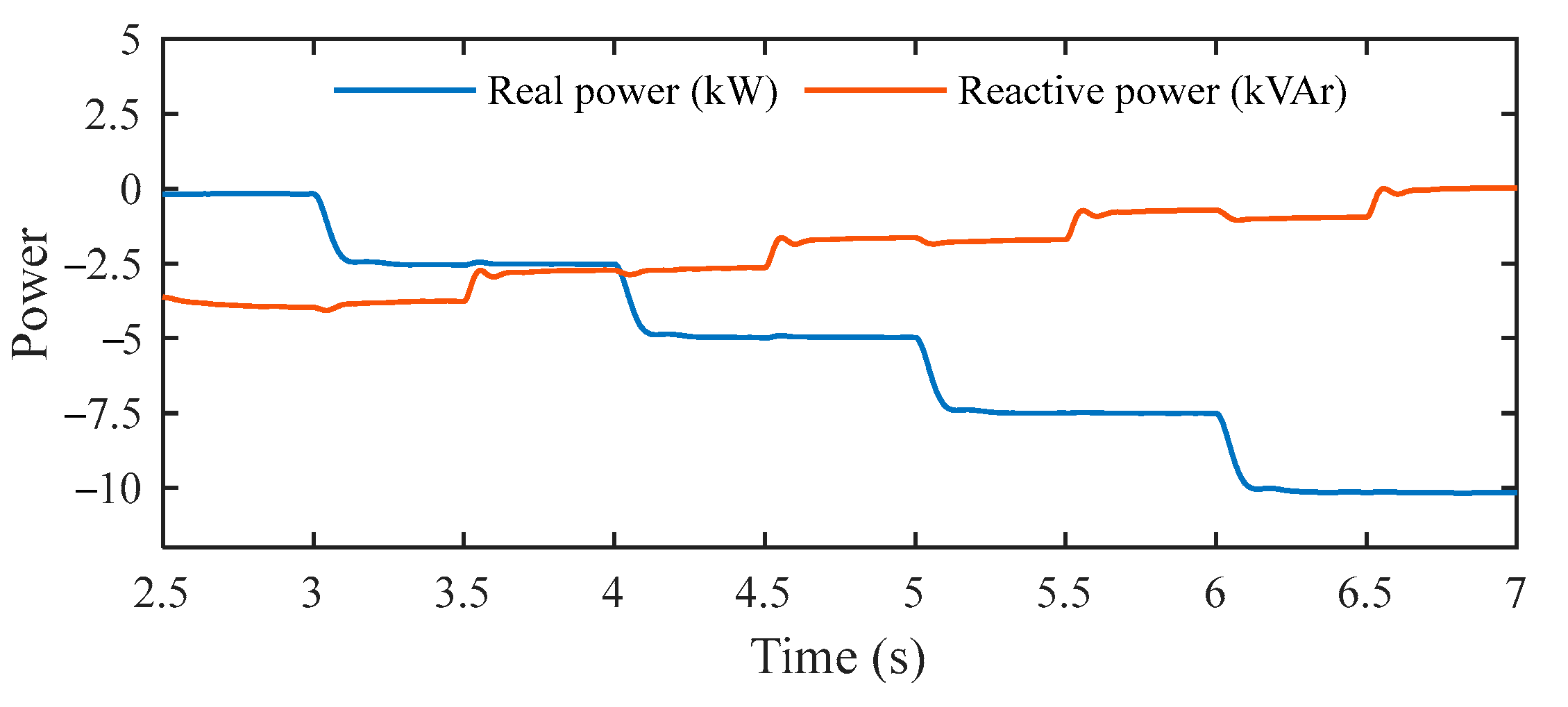
Figure 22.
Voltage and current of converter with conventional predictive control when the operation mode is changed from islanded to grid-connected mode.
Figure 22.
Voltage and current of converter with conventional predictive control when the operation mode is changed from islanded to grid-connected mode.
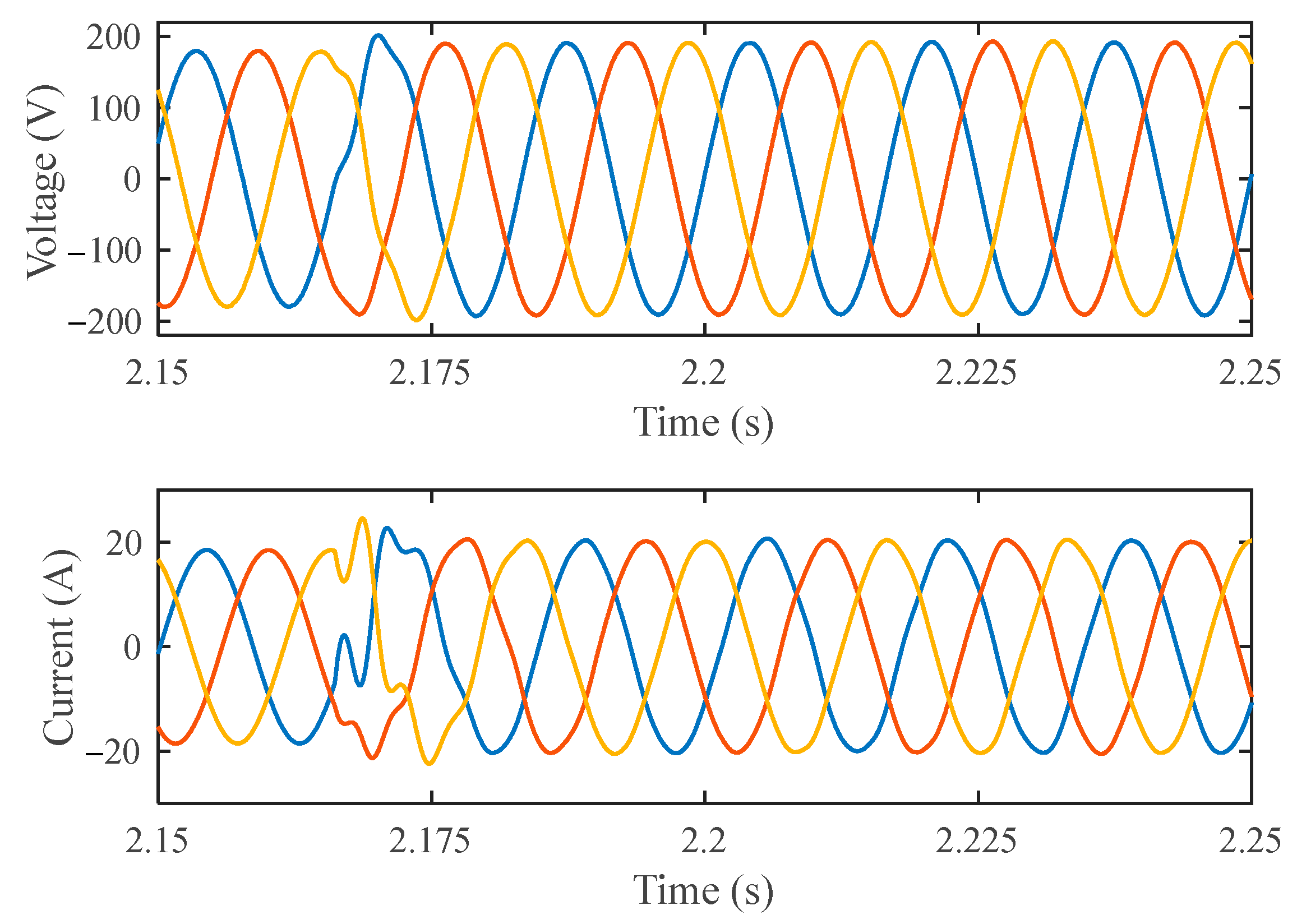
Figure 23.
Output power of the converter with conventional predictive control in the grid-connected mode.
Figure 23.
Output power of the converter with conventional predictive control in the grid-connected mode.
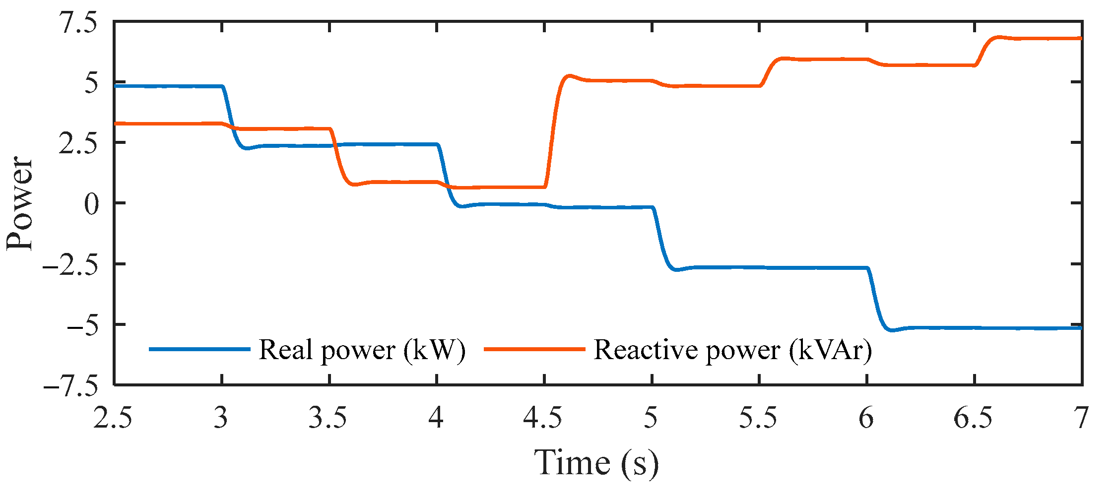
Figure 24.
Power sharing in islanded mode with conventional predictive control.
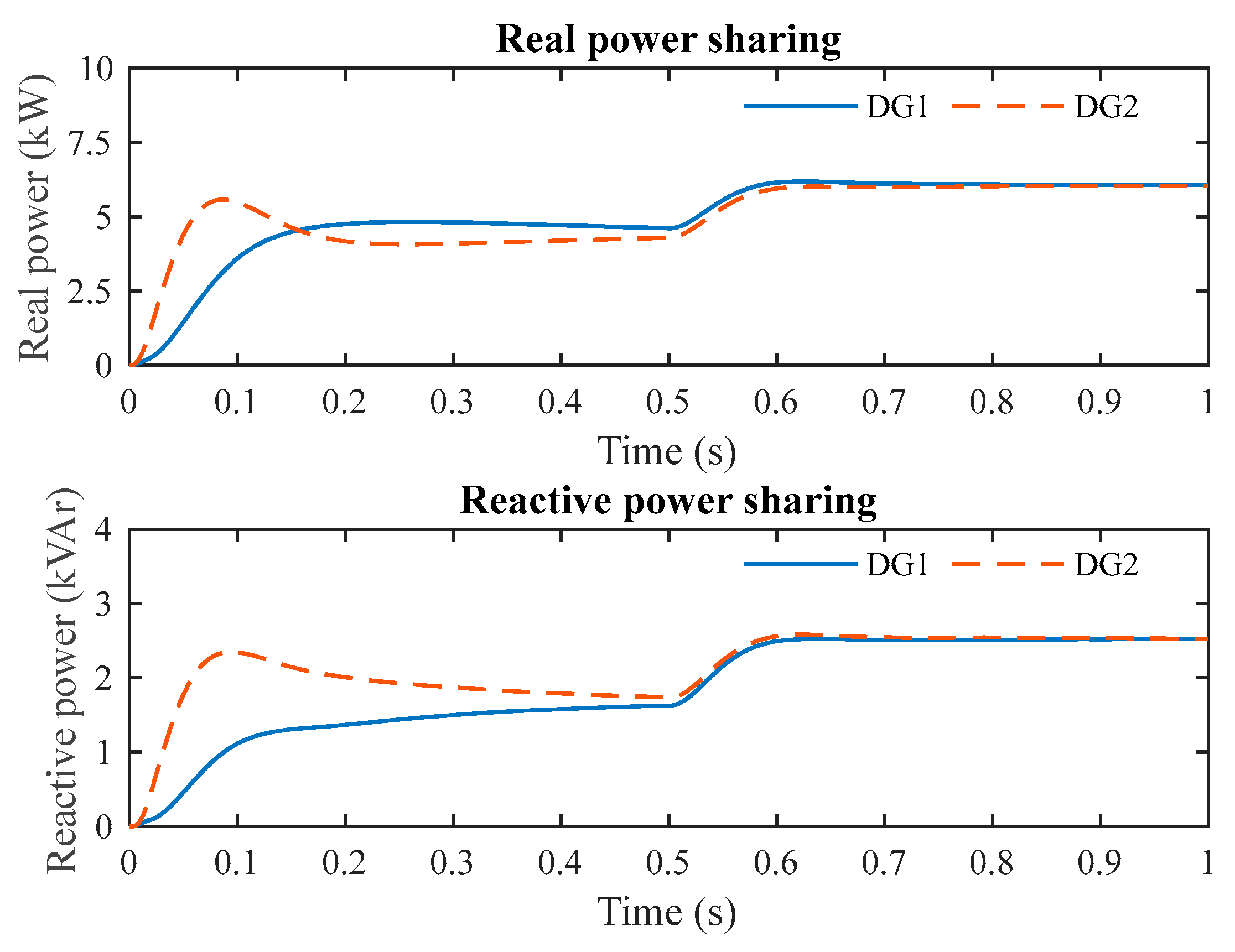
Figure 25.
Power sharing in islanded mode with the proposed predictive control method.

Figure 26.
Waveforms of voltage and current of DG1: (a) conventional predictive model; (b) proposed predictive method.
Figure 26.
Waveforms of voltage and current of DG1: (a) conventional predictive model; (b) proposed predictive method.
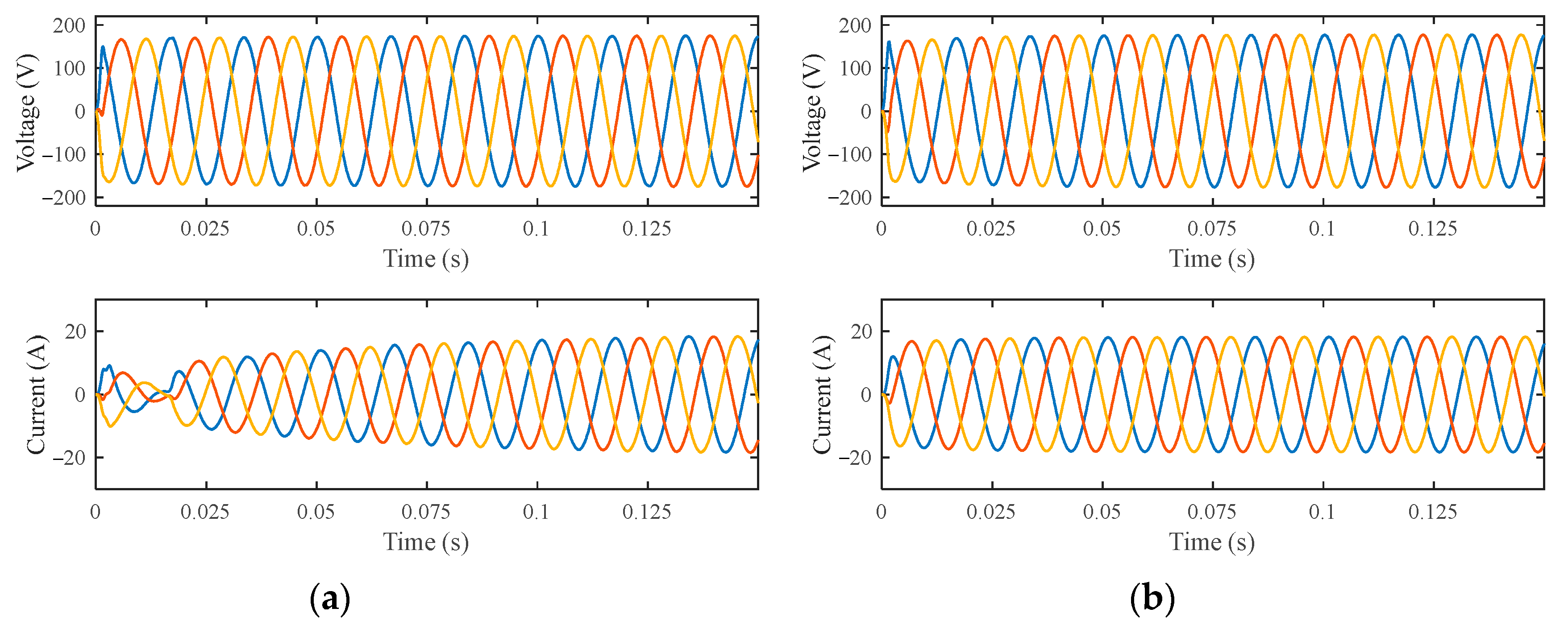
Figure 27.
Waveforms of voltage and current of DG2: (a) conventional predictive model; (b) proposed predictive method.
Figure 27.
Waveforms of voltage and current of DG2: (a) conventional predictive model; (b) proposed predictive method.

Table 1.
System Parameters.
| Parameters | Symbol | Value |
|---|---|---|
| Rated voltage and frequency | V, f | 220 V, 60 Hz |
| Base DG power | Sbase | 10 kVA |
| DC-link voltage | Vdc | 520 V |
| Filter inductance | Lf | 2.4 mH |
| Filter capacitor | Cf | 250 μF |
| Load | P, Q | 5 kW, 2 kVAr |
| Line impedance | R, L | 0.355 Ω, 1.5 mH |
DG, distributed generation; DC, direct current.
© 2018 by the authors. Licensee MDPI, Basel, Switzerland. This article is an open access article distributed under the terms and conditions of the Creative Commons Attribution (CC BY) license (http://creativecommons.org/licenses/by/4.0/).
Share and Cite
MDPI and ACS Style
Nguyen, T.-T.; Yoo, H.-J.; Kim, H.-M.; Nguyen-Duc, H. Direct Phase Angle and Voltage Amplitude Model Predictive Control of a Power Converter for Microgrid Applications. Energies 2018, 11, 2254. https://doi.org/10.3390/en11092254
AMA Style
Nguyen T-T, Yoo H-J, Kim H-M, Nguyen-Duc H. Direct Phase Angle and Voltage Amplitude Model Predictive Control of a Power Converter for Microgrid Applications. Energies. 2018; 11(9):2254. https://doi.org/10.3390/en11092254
Chicago/Turabian StyleNguyen, Thai-Thanh, Hyeong-Jun Yoo, Hak-Man Kim, and Huy Nguyen-Duc. 2018. "Direct Phase Angle and Voltage Amplitude Model Predictive Control of a Power Converter for Microgrid Applications" Energies 11, no. 9: 2254. https://doi.org/10.3390/en11092254
Note that from the first issue of 2016, this journal uses article numbers instead of page numbers. See further details here.