Visualization Study on Thermo-Hydrodynamic Behaviors of a Flat Two-Phase Thermosyphon

1
School of Hydraulic, Energy and Power Engineering, Yangzhou University, Yangzhou 225127, China
2
Jiangsu Key Laboratory of Micro and Nano Heat Fluid Flow Technology and Energy Application, School of Environmental Science and Engineering, Suzhou University of Science and Technology, Suzhou 215009, China
3
Key Laboratory of Energy Thermal Conversion and Control of Ministry of Education, School of Energy and Environment, Southeast University, Nanjing, Jiangsu 210096, China
*
Authors to whom correspondence should be addressed.
Energies 2018, 11(9), 2295; https://doi.org/10.3390/en11092295
Submission received: 20 July 2018
/
Revised: 23 August 2018
/
Accepted: 30 August 2018
/
Published: 31 August 2018
(This article belongs to the Special Issue Fluid Flow and Heat Transfer)
Abstract
:The coupled effect of boiling and condensation inside a flat two-phase thermosyphon has a non-negligible influence on the two-phase fluid flow behavior and heat transfer process. Therefore, a flat two-phase thermosyphon with transparent wall was manufactured. Based on this device, a visualization experiment system was developed to study the vapor–liquid two-phase behaviors and thermal performance of the flat two-phase thermosyphon. A cross-shaped wick using copper mesh was embedded into the cavity of two-phase thermosyphon to improve the heat transfer performance. The effects of heat flux density, working medium, and wick structure on the thermal performance are examined and analyzed. The results indicated that a strong liquid disturbance is caused by the bubble motions, leading to the enhancement of both convective boiling and condensation heat transfer. More bubbles are generated as the heat flux increases; therefore, the disturbance of bubble motion on liquid pool and condensation film becomes stronger, resulting in better thermal performance of the flat two-phase thermosyphon. The addition of the wick inside the cavity effectively reduces the temperature oscillation of the evaporator wall. In addition, the wick structure provides backflow paths for the condensate owing to the effect of capillary force and enhances the vapor–liquid phase change heat transfer, resulting in the improvement of thermal performance for the flat two-phase thermosyphon.
1. Introduction
Highly efficient cooling technologies have always been the subject of both scientific and engineering investigation in high-powered electronics circuits. Aiming to achieve highly efficient heat dissipation of high-heat-flux electronics, several advanced cooling technologies, including boiling cooling [1,2,3], liquid cooling [4,5], functional surface [6,7], microchannels heat sink [8,9,10], heat pipes [11,12,13], microfluidic engineering [14,15], metal foam [16], etc., have been introduced and applied in every field. Among these advanced cooling technologies, the heat pipes (such as grooved heat pipes [17], pulsation heat pipes [18], thermosyphons, etc.) are most widely used for the heat dissipation of microelectronic devices under high heat flux density due to high heat transfer capacity, good temperature uniformity, and no power consumption [19]. Among those heat pipes, the flat two-phase thermosyphon possesses higher heat transfer limit and superior temperature uniformity over other heat pipes, due to the operation principle of gravity-driven vapor–liquid flow and boiling phase change heat transfer [20,21]. The flat two-phase thermosyphon is considered a highly efficient heat spreader and shows good application prospects in solving uniform heat dissipation under high-heat-flux electronics [22,23,24,25,26]. Therefore, study on the flat two-phase thermosyphon’s thermal properties is of significance and has become a topic of growing technological interest during the past decades.
It should be noted that the flat two-phase thermosyphon is a confined structure, where the vapor–liquid two-phase flow self-circulates between the evaporator and condensation surface. The confinement effect in turn affects the vapor–liquid flow dynamics of the flat heat pipe. The previous investigation indicated that the bubbles generated by the evaporation surface survive on the liquid surface for a while and continue to grow, merge, and burst when the liquid level inside the cavity is low [27]. In addition, the rapid rise of bubbles can promote the liquid convection heat transfer on the evaporator surface [28,29]. Liu et al [30] add a hollow foam metal block into the cavity of a flat two-phase thermosyphon; they observed that the dense bubbles generated in the foam metal fly to the condenser surface and break, and the liquid is caused to splash to the condenser surface by the intense movement of the bubbles under the optimal filling rate. As a result, the convective boiling and film condensation heat transfer are enhanced. In summary, the coupled effect of boiling and condensation inside the flat two-phase thermosyphon has a non-negligible influence on the two-phase fluid flow behavior and heat transfer process.
Although several experimental attempts have been devoted to investigating the thermal performance of flat two-phase thermosyphons, special attention is paid to thermal performance indices, equivalent thermal conductivity, and the maximum heat transfer capacity [31,32]. For example, Lips et al. [33] found that the thermal resistance of the flat two-phase thermosyphon reduces due to the liquid retention induced by the small cavity height. Ju et al. [34] developed a flat two-phase thermosyphon incorporating hybrid wicks, which is composed of a spreading layer with low thermal resistance and a supply structure for the working medium; then, a low thermal resistance and high heat flux limit over large heating areas can be achieved. In addition, the vapor–liquid two-phase flow behaviors are complex due to the interaction between the boiling and condensation. The thermo-hydrodynamic characteristics of the two-phase thermosyphon are still waiting to be explored by visualization experiment. Still, there are few studies have been conducted to visually study the internal vapor–liquid two-phase flow behaviors and thermal performance.
Apart from experimental investigation, limited theoretical attempts on vapor–liquid two-phase flow and phase change heat transfer in the two-phase thermosyphon have been conducted. Wu et al. investigated the co-existing boiling and condensation heat transfer in a confined space using lattice Boltzmann simulation [35]. It is indicated that the interaction of condensation and boiling in a two-phase thermosyphon is embodied in the condensate droplet contact the growing bubble that contributes to bubble detachment or motion.
The heat is mainly transferred by the process of boiling and condensation inside the flat two-phase thermosiphon. However, these two processes coexist in the confined cavity and interact with each other, resulting complex vapor–liquid two-phase flow behaviors. Compared with the study of boiling or condensation in a confined space separately, the research of the coupled effect of boiling and condensation is more helpful for understanding of the thermo-hydrodynamic behaviors inside a confined space. Therefore, an experimental system is developed to visually study the vapor–liquid two-phase flow and phase change heat transfer of the thermosyphon, especially to elucidate the coupled boiling and condensation heat transfer. Through the experiment, the effects of heat flux density, working medium, and wick structure on the vapor–liquid two-phase flow behavior and thermal performance are examined and investigated.
2. Description of Experiment
2.1. Experimental Apparatus
The heat transfer performance test system is shown in Figure 1. As shown, two electric heating rods (6 mm in diameter and 50 mm in length) are embedded inside the bottom side of the copper column (20 mm in diameter and 105 mm in length). The top side of the copper column is closely contacted with the evaporator surface of the flat two-phase thermosyphon. The heating power of the electric heating rods is provided by the DC power supply. The working condition adjustment is realized by adjusting the voltage regulator and the power meter. The electric heating power ranges from 20 W to 90 W in the experiment. The constant-temperature water bath provides cooling water with a constant temperature (±0.1 °C of temperature fluctuation) for the condenser section of the flat two-phase thermosyphon. The flow meter is used to control the flow rate of the circulating water. In the experiment, the temperature of the cooling water was set to room temperature of 25 °C, and the circulating water flow rate was set to 80 mL/min.
As shown in Figure 2, the flat two-phase thermosyphon is assembled using an evaporator plate, a transparent quartz glass tube, a condenser plate, and a cooling water tank sealing plate. The glass tube is of 50 mm in outer diameter, 44 mm in inner diameter, and 3 mm in thickness. Both the evaporator and condenser plate are made of square brass plates with 54 mm in side length. The thicknesses of the evaporator and condenser plate are 5 mm and 10 mm, respectively. The evaporator and condenser surfaces are a smooth plane with a milled annular groove. Both ends of the glass tube are tightly embedded in the groove on the plate, so a closed cavity is formed. The cooling water tank is set at the back of the condenser plate and sealed by a sealing plate. The working medium is charged into the cavity through a charging hole drilled in the condenser plate. In the experiment, unless specified, deionized water was selected as the working liquid.
The CCD camera and light are used to monitor the vapor–liquid two-phase flow behavior in the cavity, and the thermocouples and data acquisition instrument are used to test the temperature changes during the experiment. Both the images and the tested temperature are recorded on the computer. In order to monitor the working conditions of the testing system, thermocouples are arranged in all parts of the system. Four thermocouple holes with a diameter of 0.5 mm and a depth of 10 mm are arranged in the upper side of the copper column, with respective distances of 5 mm, 20 mm, 35 mm, and 50 mm from the upper surface of the copper column. During operation, the heat load of the copper column imposed on the heat pipe is obtained according to the axial temperature distribution measured by the thermocouples in the copper column. The thermocouples are also arranged at the inlet and outlet of the cooling water tank for measuring the temperature change of the circulating water before and after the condenser section. Through the sensible heat gain of circulation fluid, the heat load input into the heat pipe is also obtained. The experiment test indicated that the difference of the heat load obtained by above two approaches is within 3%. Furthermore, six thermocouple holes have been arranged in the evaporator and condenser plate with the locations shown in Figure 3, so that the temperature changes of the evaporator and condenser surfaces of the flat two-phase thermosyphon can be monitored.
Through the performance test on the above experimental setup, it was indicated that there is an obvious temperature oscillation during the operation of the flat two-phase thermosyphon owing to the intermittent boiling. The presence of temperature oscillation is unfavorable for the application of flat two-phase thermosyphons. In order to eliminate the temperature oscillation, a cross-shaped wick formed by folding 200-mesh copper screen was installed into the cavity of the flat two-phase thermosyphon, as shown in Figure 4. The wick height is 15 mm, which is the same as the cavity height.
2.2. Data Reduction
The total thermal resistance of the flat two-phase thermosyphon characterizes the temperature difference required for transporting unit heat power, which is an important parameter for measuring the heat transfer performance of the flat two-phase thermosyphon. In this paper, the thermal resistance is adopted to quantitatively evaluate the heat transfer performance of the flat two-phase thermosyphon, which is defined as
where is the average temperature difference between the evaporator section and the condenser section, as follows:
where R is the total thermal resistance, and and represent the average temperatures of the evaporator section and condenser section, respectively. The subscripts 1–6 represent the temperature measurement points of the evaporator and condenser sections (P1–P6, see Figure 3). Q is the heat load. This definition characterizes the resistance of heat transfer from the evaporator surface to the condenser surface, and smaller thermal resistance means better heat transfer performance of the flat two-phase thermosyphon. The heat load can be obtained as Q = ρGCp(Tout − Tin), where ρ is density, G is the volume flow rate, Cp is specific heat, and Tout and Tin are the outlet temperature and inlet temperature, respectively, of the cooling water. The uncertainties of , Q, and R are 0.8%, 2.62%, and 2.71% according to the data error analysis.
2.3. Experiment Procedures
Before each experiment, the evaporation surface and the condensation surface were polished with metallographic abrasive paper. Then, in order to remove copper rust and dust, the surfaces were cleaned using deionized water, absolute ethanol, acetone, and deionized water in sequence. After ensuring that the evaporation plate, the condensation plate, and the quartz glass tube were clean, the two-phase thermosyphon was assembled. Then, the two-phase thermosyphon was subjected to vacuuming, liquid filling, and leak detection.
In order to ensure good repeatability of the experimental results, the experiment steps are as follows:
- (1)
- Connect each unit of the experiment system, and then perform circuit and connection checks on every unit to ensure that the experimental system is correct.
- (2)
- Open constant-temperature water bath, and adjust the temperature and flow rate to the preset values. Turn on the high-speed CCD camera to debug the shooting effect.
- (3)
- Turn on the data acquisition instrument, and observe the temperature change until the temperature at each measuring point reaches a steady state.
- (4)
- Maintain the operation of every other piece of equipment, reset the data acquisition instrument, and record the temperature data of the temperature measurement point.
- (5)
- Observe and record the gas–liquid two-phase behavior in the confined space during the start-up and quasi-steady operation in real time. Collect the temperature data. When the change of temperature is less than 0.5 °C over 20 min, the heat balance can be considered to be reached, and the experiment for the current working condition can be finished.
- (6)
- After each working condition is completed, adjust the input voltage to zero, and keep the constant-temperature water bath cooling water circulating until the temperature falls back to the initial temperature, then perform the experiment on the next working condition.
3. Results and Discussion
When there is a heat load imposed on the flat two-phase thermosyphon, the gravity-driven vapor–liquid two-phase self-circulation flow is generated in the cavity, accompanied by sensible heat transport and latent heat transport (evaporation/boiling and condensation). During this vapor–liquid phase change process, the evaporation, boiling, and condensation phase change, vapor–liquid two-phase flow, and phase interface fluctuations are very complex and coupled with each other in the flat two-phase thermosyphon. This paper began an observation of the coupled boiling and condensation phase change inside the confined cavity, and now the effects of heat flux, working medium, and wick structure on two-phase flow behaviors and thermal performance of the flat two-phase thermosyphon are examined and analyzed.
3.1. Coupled Boiling and Condensation Phase Change
The nucleate boiling occurs on the evaporator section as soon as a certain degree of superheat is achieved when the liquid continues to be heated in a two-phase thermosyphon. Figure 5 shows the typical process of nucleate boiling, namely, the bubbles generate on the evaporator surface, grow, and then detach from the surface, accompanying intense gas–liquid two-phase flow and phase change heat transfer in the cavity. As shown in the figure, bubble nucleation is first generated on the heated surface when the energy accumulates to a certain degree. Then, the bubble starts to grow according to the evaporation of the liquid microlayer at the bottom of the bubble and the heat transferring from the superheated liquid around the bubble. When the bubble grows to a certain size on the evaporator surface, it will depart from the surface by the combined effect of surface tension, buoyancy, and inertial force. After that, the bubble continues to grow to a diameter equal to the liquid level. When the bubble rises, the liquid film will be lifted directly against the condenser surface, coursing radial motion of the liquid on the condenser surface by the scour of the gas flow. The rising movement of bubbles causes strong disturbance of the liquid pool, which is beneficial for enhancing convective boiling phase change heat transfer. In addition, the condensation heat transfer can also be increased due to the scour phenomenon caused by the bubble motion on the condenser surface.
It is conceivable that during the operation of the flat two-phase thermosyphon, the boiling and condensation phase change heat transfer processes coexist and occur simultaneously inside the cavity, accompanied by complex gas–liquid two-phase flow behavior, such as bubble generation, growth, movement, coalescence, rupture, condensation, and fluctuation of the gas–liquid interface, etc. Therefore, these complex thermo-hydrodynamic behaviors play an important role in the operation and heat transfer of the flat two-phase thermosiphon.
3.2. Effect of Heat Flux
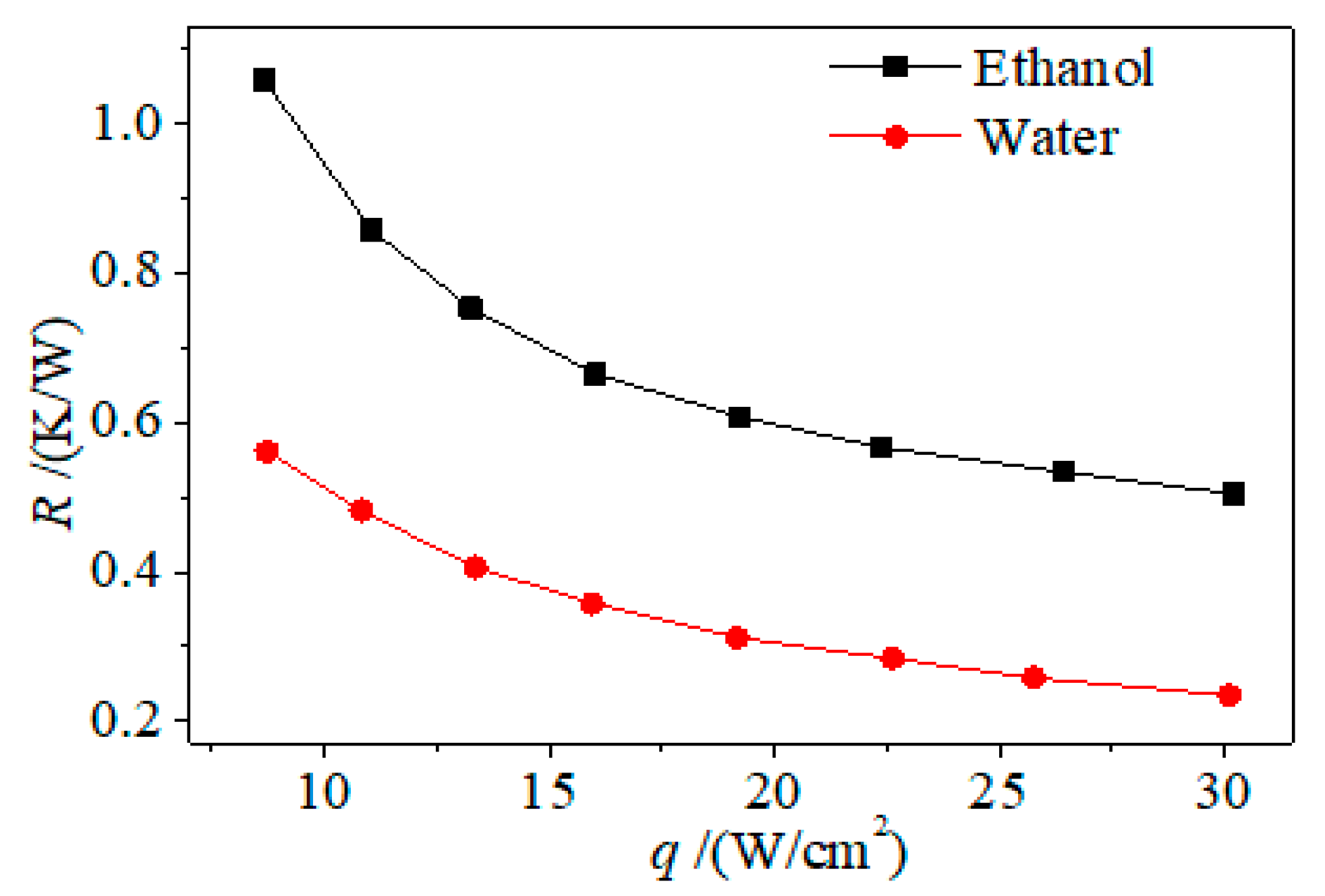
The heat flux directly determines the intensity of vapor–liquid phase change inside a confined cavity. Figure 6 shows the variation of temperature on the center point of the evaporator surface over time under different heat inputs. Figure 7 plots the total thermal resistance as a function of heat flux, and the corresponding vapor–liquid two-phase flow behaviors affected by heat flux are illustrated in Figure 7. It can be seen from the figures that, with the increase of heat flux, the thermal resistance of the flat two-phase thermosyphon shows a decreasing trend (see Figure 7), and the boiling heat transfer intensifies as indicated by increasing bubble number (see Figure 8).
When the heat flux increases, the temperature on the center point of the evaporator surface becomes higher when it reaches steady state, as shown in Figure 6. The superheat degree of the evaporator surface temperature increases, so more nucleation sites are activated, leading to generation of more bubbles. In this case, the liquid disturbance is intensified and, hence, the convective heat transfer between the liquid and solid surface is improved. As a result, the boiling heat transfer is enhanced. In addition, the condensate backflow into the liquid pool is promoted by the bubble rupture as well as the liquid flushing on the condenser surface. Induced by the stronger disturbance of the bubble by a larger heat load, the thickness of the condensate film is thinned, so the condensation heat transfer is enhanced. Therefore, as the heat load increases, the thermal resistance of the flat two-phase thermosyphon gradually becomes smaller.
It also can be seen from Figure 7 that the thermal resistance of the two-phase thermosyphon charged with water is smaller than that charged with ethanol as the working medium. This can be explained by the fact that the viscous resistance of ethanol flowing through the cavity is greater because of its higher viscosity, which causes weaker liquid disturbance and condensate backflow. Furthermore, the heat transport capacity of the ethanol is smaller than that of water due to its lower latent heat of vaporization.
3.3. Effect of Wick Presence
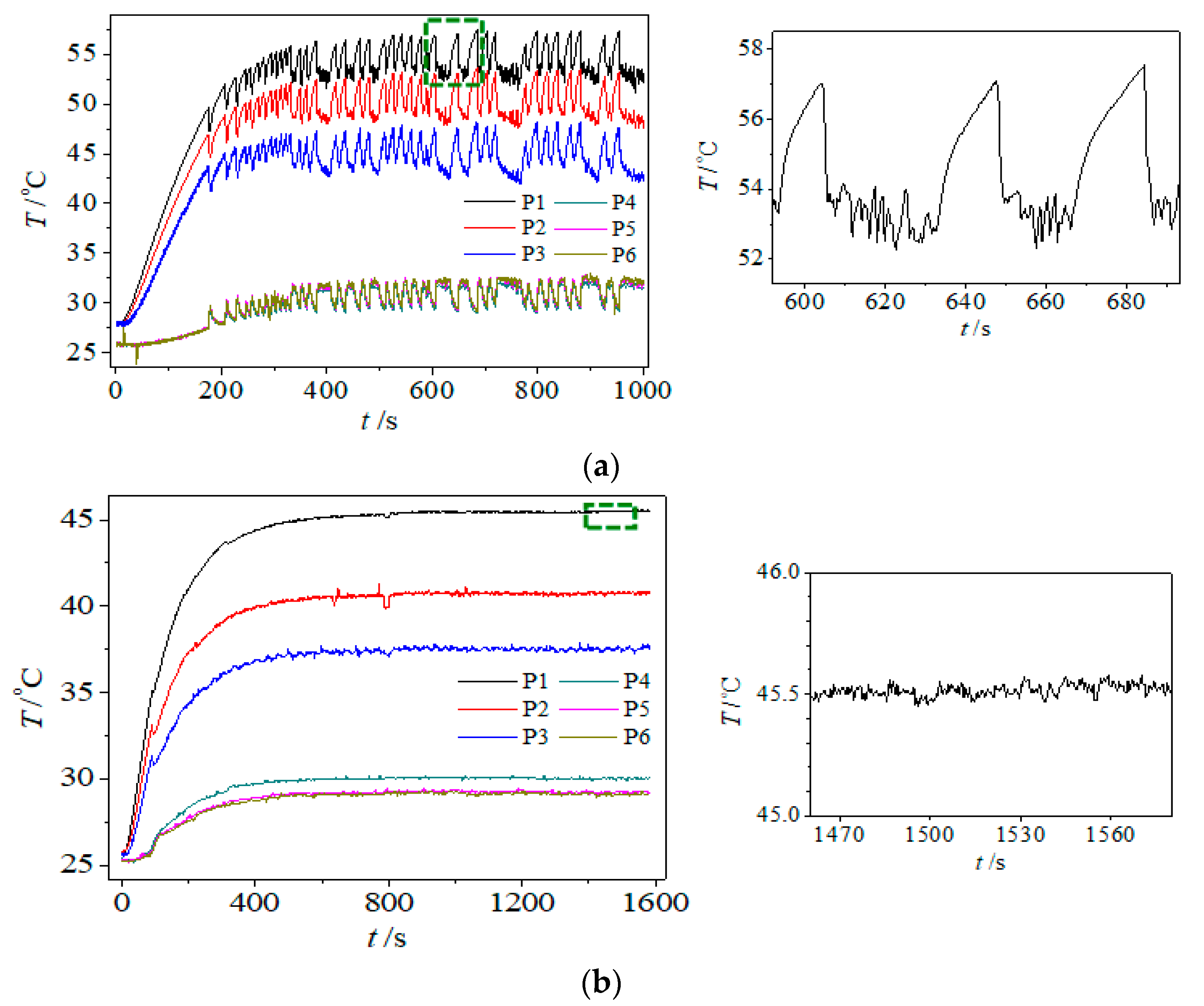
The experimental results indicated that the temperature of the evaporator wall oscillates with time when the flat two-phase thermosyphon operates. As shown in Figure 9a, there is large temperature oscillation during the quasi-steady state process, and the temperature oscillation magnitude is about 5 °C when the heat flux is 10.9 W/cm2. Note that the temperature mainly arises from the intermittent boiling when the heat flux imposed on the heat pipe is not sufficiently large. Considering the unfavorable temperature oscillation, the cross-shaped wick is introduced in this paper to eliminate the temperature oscillation. As expected, the temperature oscillation is obviously reduced once the cross-shaped wick using copper mesh is embedded into the cavity of the two-phase thermosyphon, as shown in Figure 9b. Under the case with the wick, the temperature oscillation magnitude is only about 0.15 °C, indicating the feasibility of the wick structure to enhance the operation stability of the flat two-phase thermosyphon.
Apart from the reduction of temperature oscillation, the presence of the wick structure can also improve the thermal performance of the flat two-phase thermosyphon. Figure 10 describes the thermal resistance of the flat two-phase thermosyphon with a cross-shaped wick as a function of heat flux. In order to highlight the influence of the wick structure, the thermal resistance of the flat two-phase thermosyphon without a wick is also included in the figure. It can be seen from the figure that the thermal performance of the flat two-phase thermosyphon is better than that with no wick structure. This is due to the reason that the heat is more easily transferred from the evaporator heat spot to the upper and side liquid owing to the high thermal conduction of the metal mesh wick. As shown in Figure 11, the liquid disturbance is increased as the detachment frequency and number of generated bubbles on the evaporator surface are significantly increased, so the convective boiling heat transfer of the liquid pool is improved. Besides, since the wick top contacts with the condenser surface, a shortcut of condensate backflow is provided by the wick, i.e., the condensate backflow can be promoted by the capillary force provided by the wick.
4. Conclusions
A flat two-phase thermosyphon with transparent wall was manufactured and assembled in this paper, and a visualization experiment system was developed for the visual experimental study of the boiling and condensation phase change heat transfer process inside the cavity. Considering the unfavorable temperature oscillation, a cross-shaped wick was introduced to eliminate the temperature oscillation. The effects of heat flux and wick structure on the two-phase flow behaviors and thermal performance were analyzed. The following main conclusions were obtained:
- (1)
- Contributed by the evaporation of the liquid microlayer and the heat transferring from the superheated liquid around, bubbles grow to a certain size on the evaporator surface and then depart from the surface by the combined effect of surface tension, buoyancy, and inertial force. As a result, a strong liquid disturbance caused by the bubble motions such as growth, rise, coalescence, and rupture can be observed during the experiment, which is beneficial for enhancing the phase change heat transfer processes including boiling and condensation.
- (2)
- More bubbles are generated as more nucleation sites are activated on the heated surface when the heat flux increases; therefore, the liquid disturbance is intensified and the thickness of the condensate film is thinned, leading to higher convective heat transfer and condensation heat transfer. In addition, the thermal resistance of the two-phase thermosyphon charged with water is smaller than that charged with ethanol because of lower viscosity and higher latent heat of vaporization.
- (3)
- When a wick is embedded into the cavity, more bubbles are generated and the detachment frequency is significantly increased, causing stronger liquid disturbance. Therefore, the heat is more easily transferred from the evaporator heat spot to the liquid in the cavity, leading to a decrease in the degree of superheat of the liquid. As a result, the temperature oscillation is obviously reduced.
- (4)
- As a shortcut path is constructed when a wick is used in the cavity, the backflow efficiency can be improved, resulting in the improvement of thermal performance for the flat two-phase thermosyphon.
Author Contributions
F.Y. provided guidance and supervision; C.W. implemented the main research, discussed the results, and wrote the paper; M.C.Z. collected the data; L.Y.W. and J.S. checked and revised the paper; all authors read and approved the final manuscript.
Funding
This research was funded by National Natural Science Foundation of China (grant number 51706194 and 51606037), Natural Science Foundation of Jiangsu Province (grant number BK20160687) and Natural Science Foundation of Yangzhou City (grant number YZ2017103).
Conflicts of Interest
The authors declare no conflict of interest.
References
- Liang, G.T.; Mudawar, I. Review of pool boiling enhancement with additives and nanofluids. Int. J. Heat Mass Transf. 2018, 124, 423–453. [Google Scholar] [CrossRef]
- Al-Zareer, M.; Dincer, I.; Rosen, M.A. Novel thermal management system using boiling cooling for high-powered lithium-ion battery packs for hybrid electric vehicles. J. Power Source 2017, 363, 291–303. [Google Scholar] [CrossRef]
- Zhang, C.; Chen, Y.; Wu, R.; Shi, M. Flow boiling in constructal tree-shaped minichannel network. Int. J. Heat Mass Transf. 2011, 54, 202–209. [Google Scholar] [CrossRef]
- Amalfi, R.L.; Salamon, T.; Lamaison, N.; Marcinichen, J.B.; Thome, J.R. Two-phase liquid cooling system for electronics—Part 3: Ultracompact liquid-cooled condenser. In Proceedings of the 16th Intersociety Conference on Thermal and Thermomechanical Phenomena in Electronic Systems (ITherm), Orlando, FL, USA, 30 May–2 June 2017; pp. 687–695. [Google Scholar]
- Ling, Z.; Cao, J.; Zhang, W.; Zhang, Z.; Fang, X.; Gao, X. Compact liquid cooling strategy with phase change materials for li-ion batteries optimized using response surface methodology. Appl. Energy 2018, 228, 777–788. [Google Scholar] [CrossRef]
- Zhang, C.; Deng, Z.; Chen, Y. Temperature jump at rough gas–solid interface in couette flow with a rough surface described by cantor fractal. Int. J. Heat Mass Transf. 2014, 70, 322–329. [Google Scholar] [CrossRef]
- Zhang, C.; Chen, Y.; Deng, Z.; Shi, M. Role of rough surface topography on gas slip flow in microchannels. Phys. Rev. E 2012, 86. [Google Scholar] [CrossRef] [PubMed]
- Chen, Y.; Zhang, C.; Shi, M.; Yang, Y. Thermal and hydrodynamic characteristics of constructal tree-shaped minichannel heat sink. AIChE J. 2009, 56, 2018–2029. [Google Scholar] [CrossRef]
- Najim, M.; Feddaoui, M.B.; Nait Alla, A.; Charef, A.; Kabeel, A.E. New cooling approach using successive evaporation and condensation of a liquid film inside a vertical mini-channel. Int. J. Heat Mass Transf. 2018, 122, 895–912. [Google Scholar] [CrossRef]
- Chen, Y.; Shen, C.; Shi, M.; Peterson, G.P. Visualization study of flow condensation in hydrophobic microchannels. AIChE J. 2014, 60, 1182–1192. [Google Scholar] [CrossRef]
- Chen, X.; Ye, H.; Fan, X.; Ren, T.; Zhang, G. A review of small heat pipes for electronics. Appl. Therm. Eng. 2016, 96, 1–17. [Google Scholar] [CrossRef]
- Qu, J.; Li, X.J.; Cui, Y.Y.; Wang, Q. Design and experimental study on a hybrid flexible oscillating heat pipe. Int. J. Heat Mass Transf. 2017, 107, 640–645. [Google Scholar] [CrossRef]
- Naphon, P.; Wongwises, S.; Wiriyasart, S. Application of two-phase vapor chamber technique for hard disk drive cooling of pcs. Int. Commun. Heat Mass Transf. 2013, 40, 32–35. [Google Scholar] [CrossRef]
- Chen, Y.; Gao, W.; Zhang, C.; Zhao, Y. Three-dimensional splitting microfluidics. Lab Chip 2016, 16, 1332–1339. [Google Scholar] [CrossRef] [PubMed]
- Chen, Y.P.; Deng, Z.L. Hydrodynamics of a droplet passing through a microfluidic t-junction. J. Fluid Mech. 2017, 819, 401–434. [Google Scholar] [CrossRef]
- Deng, Z.; Liu, X.; Zhang, C.; Huang, Y.; Chen, Y. Melting behaviors of pcm in porous metal foam characterized by fractal geometry. Int. J. Heat Mass Transf. 2017, 113, 1031–1042. [Google Scholar] [CrossRef]
- Chen, Y.; Zhang, C.; Shi, M.; Wu, J.; Peterson, G.P. Study on flow and heat transfer characteristics of heat pipe with axial “Ω”-shaped microgrooves. Int. J. Heat Mass Transf. 2009, 52, 636–643. [Google Scholar] [CrossRef]
- Deng, Z.; Zheng, Y.; Liu, X.; Zhu, B.; Chen, Y. Experimental study on thermal performance of an anti-gravity pulsating heat pipe and its application on heat recovery utilization. Appl. Therm. Eng. 2017, 125, 1368–1378. [Google Scholar] [CrossRef]
- Qu, J.; Wu, H.Y.; Cheng, P.; Wang, Q.; Sun, Q. Recent advances in mems-based micro heat pipes. Int. J. Heat Mass Transf. 2017, 110, 294–313. [Google Scholar] [CrossRef]
- Lv, L.; Li, J. Managing high heat flux up to 500w/cm2 through an ultra-thin flat heat pipe with superhydrophilic wick. Appl. Therm. Eng. 2017, 122, 593–600. [Google Scholar] [CrossRef]
- Zhang, M.; Liu, Z.; Ma, G. The experimental investigation on thermal performance of a flat two-phase thermosyphon. Int. J. Therm. Sci. 2008, 47, 1195–1203. [Google Scholar] [CrossRef]
- Chang, S.W.; Yu, K.C. Thermal performance of reciprocating two-phase thermosyphon with nozzle. Int. J. Therm. Sci. 2018, 129, 14–28. [Google Scholar] [CrossRef]
- Fertahi, S.E.D.; Bouhal, T.; Agrouaz, Y.; Kousksou, T.; El Rhafiki, T.; Zeraouli, Y. Performance optimization of a two-phase closed thermosyphon through cfd numerical simulations. Appl. Therm. Eng. 2018, 128, 551–563. [Google Scholar] [CrossRef]
- Narcy, M.; Lips, S.; Sartre, V. Experimental investigation of a confined flat two-phase thermosyphon for electronics cooling. Exp. Therm. Fluid. Sci. 2018, 96, 516–529. [Google Scholar] [CrossRef] [Green Version]
- Wang, X.Y.; Wang, Y.F.; Chen, H.J.; Zhu, Y.Z. A combined cfd/visualization investigation of heat transfer behaviors during geyser boiling in two-phase closed thermosyphon. Int. J. Heat Mass Transf. 2018, 121, 703–714. [Google Scholar] [CrossRef]
- Fadhl, B. Modelling of the Thermal Behaviour of a Two-Phase Closed Thermosyphon. Ph.D. Thesis, Brunel University London, London, UK, March 2016. [Google Scholar]
- Zhang, G.; Liu, Z.; Wang, C. An experimental study of boiling and condensation co-existing phase change heat transfer in small confined space. Int. J. Heat Mass Transf. 2013, 64, 1082–1090. [Google Scholar] [CrossRef]
- Chen, Y.; Yu, F.; Zhang, C.; Liu, X. Experimental study on thermo-hydrodynamic behaviors in miniaturized two-phase thermosyphons. Int. J. Heat Mass Transf. 2016, 100, 550–558. [Google Scholar] [CrossRef]
- Zhang, G.; Liu, Z.; Wang, C. A visualization study of the influences of liquid levels on boiling and condensation co-existing phase change heat transfer phenomenon in small confined spaces. Int. J. Heat Mass Transf. 2014, 73, 415–423. [Google Scholar] [CrossRef]
- Liu, Z.L.; Zheng, F.W.; Li, Y.X. Enhancing boiling and condensation co-existing heat transfer in a small and closed space by copper foam inserts. Int. J. Heat Mass Transf. 2017, 108, 961–971. [Google Scholar] [CrossRef]
- Peng, H.; Li, J.; Ling, X. Study on heat transfer performance of an aluminum flat plate heat pipe with fins in vapor chamber. Energy Convers. Manag. 2013, 74, 44–50. [Google Scholar] [CrossRef]
- Hassan, H.; Harmand, S. An experimental and numerical study on the effects of the flat heat pipe wick structure on its thermal performance. Heat Transf. Eng. 2015, 36, 278–289. [Google Scholar] [CrossRef]
- Lips, S.; Lefevre, F.; Bonjour, J. Combined effects of the filling ratio and the vapour space thickness on the performance of a flat plate heat pipe. Int. J. Heat Mass Transf. 2010, 53, 694–702. [Google Scholar] [CrossRef]
- Ju, Y.S.; Kaviany, M.; Nam, Y.; Sharratt, S.; Hwang, G.S.; Catton, I.; Fleming, E.; Dussinger, P. Planar vapor chamber with hybrid evaporator wicks for the thermal management of high-heat-flux and high-power optoelectronic devices. Int. J. Heat Mass Transf. 2013, 60, 163–169. [Google Scholar] [CrossRef]
- Wu, S.; Yu, C.; Yu, F.; Chen, Y. Lattice boltzmann simulation of co-existing boiling and condensation phase changes in a confined micro-space. Int. J. Heat Mass Transf. 2018, 126, 773–782. [Google Scholar] [CrossRef]
Figure 1.
Schematic of experimental setup: (a) system diagram; (b) experimental rig.

Figure 2.
Schematic of the flat two-phase thermosyphon.

Figure 3.
Schematic of temperature measuring points: (a) thermocouple positions; (b) diagram of temperature measuring in the two-phase thermosyphon.
Figure 3.
Schematic of temperature measuring points: (a) thermocouple positions; (b) diagram of temperature measuring in the two-phase thermosyphon.

Figure 4.
Structure of the cross-shaped wick: (a) picture of cross-shaped wick; (b) dimensions of cross-shaped wick.
Figure 4.
Structure of the cross-shaped wick: (a) picture of cross-shaped wick; (b) dimensions of cross-shaped wick.

Figure 5.
The evolution of gas–liquid two-phase flow pattern in cavity (φ = 80%, q = 17.7 W/cm2, H = 20 mm).
Figure 5.
The evolution of gas–liquid two-phase flow pattern in cavity (φ = 80%, q = 17.7 W/cm2, H = 20 mm).

Figure 6.
Effect of heat input on the temperature of the center point on evaporator surface.

Figure 7.
Effect of heat input on thermal resistance (φ = 65%).

Figure 8.
Effect of heat flux on two-phase flow behavior (working medium: water).

Figure 9.
Effect of wick presence on evaporator wall temperature evolution: (a) no wick (φ = 50%, q = 10.9 W/cm2, H = 15 mm); (b) cross-shaped wick (φ = 50%, q = 9.9 W/cm2, H = 15 mm).
Figure 9.
Effect of wick presence on evaporator wall temperature evolution: (a) no wick (φ = 50%, q = 10.9 W/cm2, H = 15 mm); (b) cross-shaped wick (φ = 50%, q = 9.9 W/cm2, H = 15 mm).

Figure 10.
Effect of wick presence on thermal resistance (H = 15 mm, φ = 50%).

Figure 11.
Evolution of vapor–liquid two-phase flow inside the wick thermosyphon (H = 15 mm, φ = 50%, q = 20 W/cm2).
Figure 11.
Evolution of vapor–liquid two-phase flow inside the wick thermosyphon (H = 15 mm, φ = 50%, q = 20 W/cm2).

© 2018 by the authors. Licensee MDPI, Basel, Switzerland. This article is an open access article distributed under the terms and conditions of the Creative Commons Attribution (CC BY) license (http://creativecommons.org/licenses/by/4.0/).
Share and Cite
MDPI and ACS Style
Wang, C.; Yao, F.; Shi, J.; Wu, L.; Zhang, M. Visualization Study on Thermo-Hydrodynamic Behaviors of a Flat Two-Phase Thermosyphon. Energies 2018, 11, 2295. https://doi.org/10.3390/en11092295
AMA Style
Wang C, Yao F, Shi J, Wu L, Zhang M. Visualization Study on Thermo-Hydrodynamic Behaviors of a Flat Two-Phase Thermosyphon. Energies. 2018; 11(9):2295. https://doi.org/10.3390/en11092295
Chicago/Turabian StyleWang, Chao, Feng Yao, Juan Shi, Liangyu Wu, and Mengchen Zhang. 2018. "Visualization Study on Thermo-Hydrodynamic Behaviors of a Flat Two-Phase Thermosyphon" Energies 11, no. 9: 2295. https://doi.org/10.3390/en11092295
Note that from the first issue of 2016, this journal uses article numbers instead of page numbers. See further details here.