Interoperability Testing Methodology for Smart Grids and Its Application on a DSM Use Case—A Tutorial


1
Energy Security, Distribution and Markets Unit, Directorate of Energy, Transport and Climate, Joint Research Centre, 21027 Ispra, Italy
2
Energy Security, Distribution and Markets Unit, Directorate of Energy, Transport and Climate, Joint Research Centre, 1755 LE Petten, The Netherlands
*
Author to whom correspondence should be addressed.
Energies 2019, 12(1), 8; https://doi.org/10.3390/en12010008
Submission received: 5 November 2018
/
Revised: 7 December 2018
/
Accepted: 13 December 2018
/
Published: 20 December 2018
(This article belongs to the Section F: Electrical Engineering)
Abstract
:Interoperability is a challenge for the realisation of smart grids. In this work, we first present an interoperability testing methodology, which is substantial to perform interoperability tests for the smart grid. To show its applicability and facilitate its comprehension, we present an example by applying it on a Demand Side Management (DSM) use case. The DSM use case is chosen because it is a major topic for modern grids and it involves the participation of many actors. The tutorial exemplifies the interactions among those actors. The Smart Grid Architecture Model SGAM framework is used, where the mapping of the use case is presented along with the Message Sequence Chart (MSC). Then we describe the profiling of the equipment, relevant technical information and standards, which form the basis for the design and execution of the interoperability tests. We focus on the technical part of the interoperability testing; therefore, attention is focused on the information and communication layer. We present how the interoperability tests should take place and we analytically show the respective Test Cases (TC). The verdict of the test should be either PASS or FAIL. The paper shows how to successfully use the methodology for interoperability testing on a specific use case, whereas its applicability can be extended to any smart grid interoperability use case.
1. Introduction
The Smart Grid exhibits a high complexity regarding organisational and technological issues. The key challenge of the Smart Grid is integration, which in turns affects all the components, systems, applications and information involved. Telecommunications play an important role for the realisation of the smart grid, since they enable data exchange between components. There is a plethora of telecommunication technologies that can be utilized for the smart grid depending on the application, either wireless or wired [1,2].
In general, there are three main domains of applications for the smart grid network: the High Voltage (HV) network used for the electricity transmission, the Medium Voltage (MV) network used for the electricity distribution and the Low Voltage (LV) network used to provide electricity to end-users [3]. In addition, functionalities and interfaces should enable interaction so as to execute all the necessary processes within the system. Thus interoperability is an essential requirement for the Smart Grid interoperability, a technical imperative, and the enabler of an open market where innovation can flourish.
Interoperability refers to the ability of two or more devices from the same vendor, or different vendors, to exchange information and use that information for correct co-operation [4]. As stated by the CEN-CENELEC-ETSI Smart Grid Coordination Group (SG-CG) [5], this definition is extended to “The ability of two or more networks, systems, devices, applications, or components to interwork, to exchange and use information in order to perform required functions.” In addition, “Interoperability between systems in a smart grid must be considered and well specified in use cases, in order to develop interoperable Smart Grid systems by design. Use cases provide a basis for the specification of functional requirements, non-functional requirements, Test Cases (TC) and test profiles”.
A framework that has been used for Interoperability purposes is the Smart Grid Architecture Model SGAM model, which stands for “Smart Grid Architecture Model” and is the main outcome of Reference Architecture working group mandated by the EU’s 490 Mandate [6] entitled “Smart Grid Mandate–Standardization Mandate to European Standardization Organizations (ESOs) to support European Smart Grid deployment”.
Based on the SGAM framework there are five different layers of interoperability:
- Business layer which represents the business view on the information (business models, market structures, business portfolios etc.)
- Functional layer specifying the functions and services
- Information layer which is the data model to be used to ensure a common understanding of the data exchanged
- Communication layer which is the communication technology (e.g., PLC or Ethernet) and the communication protocol for data transmission
- Component layer which is the hardware to connect systems or devices such as power cables (physical distribution)
This means that all interactions (i.e., physical, information-based and process-based) should satisfy the interoperability principle. This includes the field level (e.g., substation automation, distribution automation, distributed energy resources), to remote operations (e.g., remote grids management), market management, service management, customer management, etc. A major challenge for interoperability is the integration across domains.
Figure 1 presents the SGAM model with the mapping of different types of interoperability. The additions made clarify the field regarding the different types of interoperability available and their connection to different interoperability layers.
There have been several attempts in the literature to address the issue of interoperability on the smart grid. Interoperability for digital substation devices and the information exchange among them is the topic of reference [8]. In particular, they assess the interoperability between such devices which use the IEC 61850 standard. In reference [9] they propose an agent framework that has been assessed through a lab testbed for interoperability purposes. Intelligent physical agents, the IEC 61850 and data distribution service standards have been used. Interoperability for phasors is studied in reference [10], where a security gateway is also examined for synchrophasor applications in terms of interoperability and integration. In reference [11] interoperability for sensors is addressed. The need for the smart grid sensors to be interoperable is highlighted and sensor interface standards are described. They also perform interoperability tests on smart grid sensors. Interoperability for sensors is also examined in reference [12], where a testbed is suggested for testing interoperability of smart sensors. For this purpose, they perform tests of commercial sensors. Data and protocol interoperability are discussed in reference [13]; a data distribution service is examined for this purpose, whereas a data model is used for configuration of TCP/IP and UDP/IP. The need for interoperable Neighbourhood Access Network NAN communication standards is addressed in reference [14]. The problem of interoperability is also discussed in reference [15], where data and communication issues are examined. They also study the case of publish-subscribe communication techniques as a way to improve communication and resolve interoperability. Communication interoperability is also the topic of reference [16], where the communication network requirements are examined for smart grid interoperability.
From the above, it is clear that interoperability is an important issue to be addressed for the smart grid, and interoperability testing is very important. The way to achieve Smart Grid system interoperability is through detailed system specification, through use of standards, and through testing. In order to demonstrate that two implementations are interoperable, several steps should be taken, such as: the definition of functionalities, the selection of standards, and creation of profiles and of course the testing which includes both the conformance and the interoperability testing. Therefore a systematic methodology should be applied to reach interoperability.
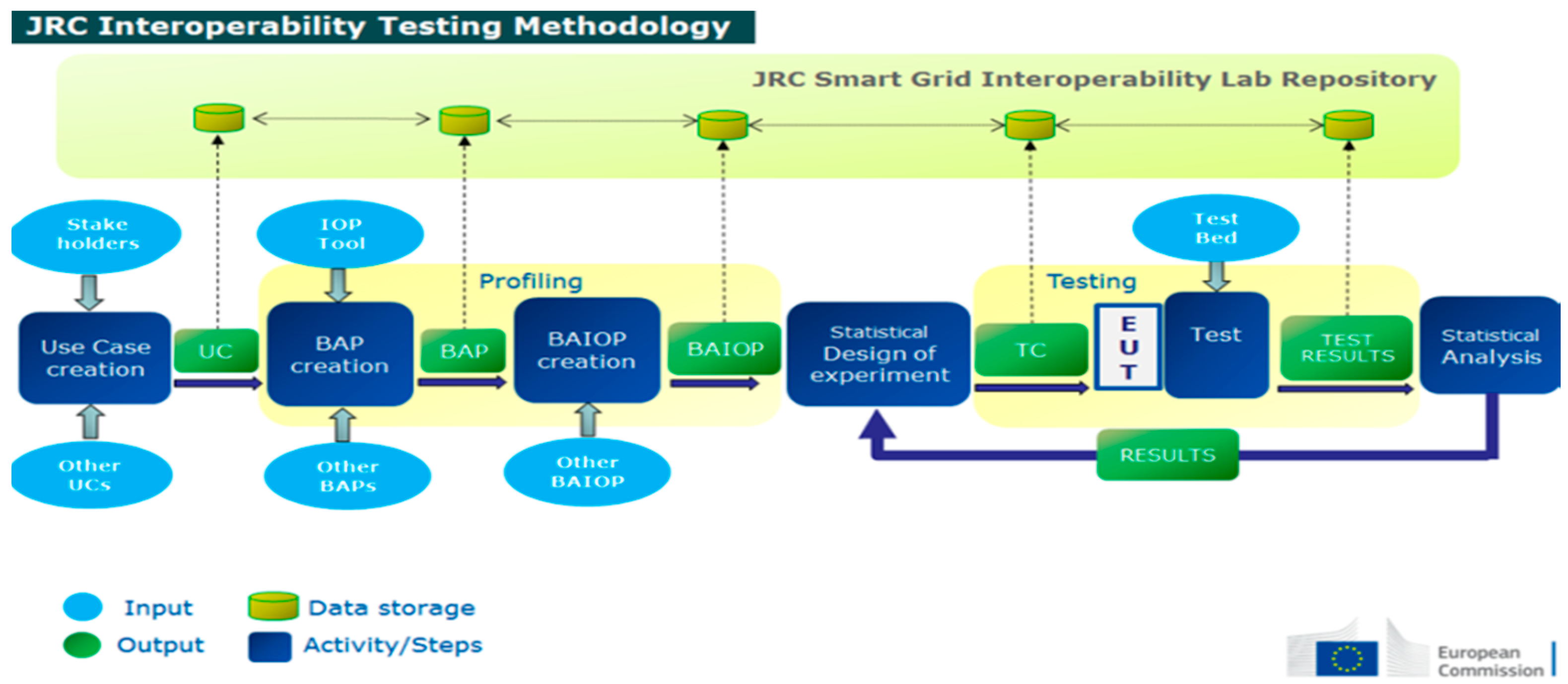
The Smart Grid Interoperability Laboratory (SGILab) at the Joint Research Centre (JRC) of the European Commission proposes in this document a unified approach towards a European framework for developing interoperability testing specifications, as shown in Figure 2 [17]. A successful development and deployment of the future smart grid requires a better understanding of how components interoperate and how the proposed standards ensure interoperability among those components. Towards this objective a methodology serves as a systematic way to evaluate the interoperability of different subsystems or electric grid components and methodically verify the ability of a given equipment under test to communicate effectively with other components. The use of a methodology provides a systematic means to analyse any interoperation flaw against business and user requirements. Further analysis could then be utilised to assess the impact of any inconsistency and propose potential solutions.
We further apply the proposed methodology to a use case with a focus on the first two steps (as explained in Section 2) in order to give a practical example of its application and to show the benefits of a structured procedure of interoperability testing. The Use Case used for this purpose is the “Load Management Based on Demand Response (DR)/Demand Side Management (DSM)”, which we have developed for the scope of applying our proposed methodology. We chose this use case, since Flexibility in Demand is a topic of key scientific interest, which aims at adjusting and/or shifting load consumption in order to avoid peaks in demand and it is considered vital for grid stability. Demand Response (DR) and Demand Side Management (DSM) are two actions utilised in order to achieve flexibility in demand and generation in the distribution level. In both cases, it is fundamental that the customer is actively involved in load management, whereas it is considered that both industrial and residential consumers can contribute in the realisation of the fully operating smart grid. The meaning and the differences between the two concepts of DR and DSM is explained as follows [18]:
- Demand Response is considered to be a bottom-up approach: the customer is provided with incentives so as to become active in load management and to shift/curtail loads. Such incentives can be convenient tariff schemes or economic benefits in general. In any case, the customer is responsible for managing his/her consumption.
- Demand Side Management is considered a top-down approach: the energy provider/energy service company/aggregator is responsible for reducing or removing peak loads. Such an actor decides on measures to be implemented so as to increase the grid’s stability by shifting or curtailing loads.
DR has also been the argument of several international projects realised in Europe. For instance, in the Scalable Energy Management Infrastructure for Aggregation of Households (SEMIAH) project they implement a system for DR services based on aggregation and scheduling of electricity loads in households [19]. In the Peer-to-peer Smart Test (P2P SmarTest) project, special focus is given to market issues and the market models/competition relationships between different actors. It is suggested how to define the baseline methodology, how to design demand response products, the measurement and validation activities, the bidding process for implementing demand response and how to remove potential barriers in the system [20].
DR/DSM is a topic which attracts considerable scientific interest, with numerous articles in the literature addressing such issues. In reference [21] the distributed demand response (DDR) problem has been examined, where real-time balance in a neighbourhood has been studied. In reference [22], a distributed mechanism for demand response aggregation has been proposed. The mechanism is used for charging purposes and uses the day-ahead allocation and the customers’ real consumption. Communication aspects in DR have been examined in reference [23], where residential customers are encouraged to participate in a DR program, even without the employment of a smart meter. In reference [24], the authors suggest a system for DSM, using the strategies of load shifting, flexible load shape, peak clipping, among others. DSM is also the focus of reference [25], where an electric vehicle charging schedule is proposed. The usage of a microcontroller associated with wireless telecommunication technologies is examined for the implementation of DSM in reference [26]. Market issues for DSM are examined in reference [27] with internal pricing being used for regulation service provisioning. Price responsive controllable loads is the topic of research in reference [28], highlighting the importance of customer involvement in DSM/DR programs. In reference [29], a distributed demand side energy management system is used, where an energy consumption scheduling game is used. The schedule of residential loads of each user is actually his/her strategies used. In reference [30] a specific DR program has been examined in terms of standards in DR communication. They aimed at increasing interoperability with respect to a DR communication standard. The OpenADR has been also examined and it has been found that the program had gaps regarding OpenADR. The whole work aimed at improving interoperability aspects of DR programs. In reference [31] a DSM test case has been applied on an end-to-end system, from the consumer to the energy provider. The paper focuses on the technical aspects of a simple demand side management program, whereas a lab environment test bed has been used that represents a number of actors involved in the interaction between the consumer and the energy provider for a DSM/ DR action to take place.
There are also other use cases that developed that deal with DR/DSM. In references [32,33] the use cases proposed address DR in terms of load profile management via pricing mechanisms and via reliability based signals, respectively. In reference [34] a use case on load management through dynamic tariffs is presented, whereas in reference [35] DR is addressed through utility commanded load control. Additionally, in reference [36], the event of direct load control is examined. The importance of customer involvement (residential and commercial) is highlighted in reference [37], where the case of customers responding to DR signals from utility and implementing DR is showed. Automation functions on the customer side are also described in use cases, i.e., in reference [38] the provisioning of a DR Home Area Network (HAN) device is proposed, whereas in reference [39] the authors discuss how the pricing data and the DR event messages are passed to HAN devices along with customer acceptance or not.
In this work we follow the proposed methodology to define the examined use case, the actors involved and the interaction steps required. Further on, we map the use case to the interoperability layers of interest and we define the link and the actors involved in the interoperability test. Finally, we define the profiling procedure (BAP and BAIOP) with respect to interoperability.
In contrast to reference [31], in this work we focus on the interoperability methodology and the necessary steps to perform interoperability tests. The example of the DSM use case is used to prove the applicability of the methodology on a real use case. In reference [31], focus is given on the experimental aspects of a DSM test and the interaction between customer and energy provider; no interoperability issues are examined. In addition, whereas a simplified version of a DSM case that would fit in a lab environment is described in reference [31], in this work we use the full chain of actors and their interactions that would be present in a real large-scale system to show the applicability of the interoperability methodology. The DSM case is used here as an example for the methodology; the interoperability test steps are described, however, it is out of the scope of this tutorial to provide additional experimental results and address technical issues with respect to the experimental part.
Our contribution is summarised as follows:
- We provide a structured methodology for interoperability testing which can become a valuable tool for researchers and engineers in order to validate the correct operation and exchange of information between different components of the smart grid. The proposed methodology is a complete tool for interoperability testing, which is missing from what already exists in the literature and can be applied in any smart grid interoperability use case.
- The methodology gives the total sequence of steps to be followed, from the use case creation to the test results and statistical analysis and takes into account the SGAM model.
- An example is given that shows how to apply this methodology: a use case is created and the methodology steps are followed for an interoperability test. The test steps are described. Through the given example, the reader can have a clear idea of how to implement the methodology on a smart grid interoperability use case.
- The use case selected for this tutorial is a demand side management use case; it describes the interaction between the energy provider and customer and it involves many actors in the chain from energy provider and end user. This use case gives an insight of how these actors can interact and their depiction on the SGAM gives feedback on the plethora of standards that can be used in each data exchange link.
The rest of the paper is organized as follows. Section 2 presents the proposed methodology. Section 3 describes the examined use case and defines the interoperability test to be further analysed. Section 4 presents the profiling procedure (BAP and BAIOP) with respect to the layers if interest. Section 5 discusses the conclusions derived from this work.
2. Proposed Methodology
The SG-CG of CEN/CENELEC in the “Methodologies to facilitate Smart Grid system interoperability through standardisation, system design and testing” [40] report has illustrated the process to achieve interoperability with the use of Use Cases, Basic Application Profiles (BAP) and Basic Application Interoperability profiles (BAIOP). Our proposed methodology takes into account the process proposed in reference [40] and extends it. The phases of the process that we propose are listed as follows:
- Creation of Use Case with the input from stakeholders
- Profiling by creating Basic Application Profiles and Basic Application Interoperability Profiles
- Testing which includes the test beds, the Equipment Under Test, the Design of the Experiment and of course the IOP testing
- Analysing the results with (possible) feedback to the testing phase for further exploring
The block diagram of the JRC Interoperability Methodology (including, inputs, activities, outputs and data storage) is depicted in Figure 2. The activities of the process are defined as explicit steps that have to be followed to execute the Methodology:
- Step 1: Use Case Elaboration
- Step 2: Basic Application Profiles (BAP) creation
- Step 3: Basic Application Interoperability Profiles (BAIOP) creation
- Step 4: Statistical Design of experiments (DoE)
- Step 5: Testing
- Step 6: Statistical Analysis of experiments
3. DSM Use Case
3.1. Use Case Description
The Use Case to be examined is entitled: “Load Management Based on Demand Response/Demand Side Management”. For accomplishing load management through DR/DSM, a system comprising of at least one energy provider, one energy management actor and some end-users is required. The consumption of end-users is monitored through the smart meter readings sent regularly to the energy provider. This monitoring is performed at an aggregator level, meaning that the energy provider is mostly interested in the consumption as a whole from all consumers. It should also be noted that all end-users have the contracted power. In order to draw useful conclusions about consumption behaviours, the monitoring should be done for a specific time period that would allow for the observation of periodical trends on behalf of the consumers.
In order to avoid peaks in the overall load demand, load shifting is decided and planned. Further on, messages are sent to the end-users through an application inviting them to take part in the DR/DSM program. In case of a positive feedback, an actor like an energy service company takes control of certain domestic electrical devices programming their functionality. The energy provider monitors the new situation and conclusions are drawn with respect to the actions taken.
This use case can be examined for interoperability purposes in case a new end-user (new smart meter) is integrated in the system. The system should operate the same with the old and the new end-user(s).
As a first step, we need to identify the actors that are involved in this use case and the interactions between them. For this scope, we have decided to entail as many actors as possible that would depict a real system in the most possible accurate way and information from reference [41] has also been taken into account. The list of actors is shown in Table 1.
The interactions between the aforementioned actors are shown in the Message Sequence Chart (MSC), which is displayed in Figure 3. As it can be observed, smart meter readings are sent to the data concentrator (NNAP) and subsequently they are forwarded to the HES and the MDMS, where the user consumption profile data is extracted. Actor A controls the metering channel, thus it is the point where elaborated smart meter data forming the user consumption profile are collected. Actor A controls the energy channel and needs to interact with Actor B in order to obtain information with respect to the users that have a contract with both Actors. Actor A is the one interacting with the consumer in order to invite him/her to participate in a potential DR/DSM program. It is assumed that a consumer application is available for this purpose through which the end-user sends the feedback.
For completing the picture, at the customer premises, there is a Customer Energy Management System (CEMS), which is controlled externally by Actor A and further controls the smart device(s). In the presence of regular appliances within the house, a home automation end device is needed, which interacts with the CEMS and the non-smart appliance. Such a device can be a controllable plug or a software capable of controlling when a regular electrical device will be switched on and off.
It is assumed that: the home customer has a contract both with Actor A and with Actor B; the data is transmitted without errors; user profile is correct; customer and Actor A can interact correctly with the consumer application. The step by step analysis of the described use case is described in Table 2. In the described steps, alternative scenarios have not been taken into consideration.
3.2. Mapping of Use Case to SGAM Layers
In this section we depict the mapping of the use case on the SGAM interoperability layers. Figure 4 shows a possible mapping of the Load Management Based on Demand Response/Demand Side Management Use Case at the Component Layer. It should be noted that the grey area at the graph indicates that the respective assets in the building/home may not be owned by the electricity service supplier, but by the customer. This scheme is not definite as Member State market models can vary.
Figure 5 shows a possible mapping of the Load Management Based on Demand Response/Demand Side Management Use Case at the Business Layer. The diagram shows the areas which are affected by the use case and influenced by underlying business objectives.
Figure 6 shows a possible mapping of the Load Management Based on Demand Response/Demand Side Management Use Case at the Function Layer. It represents functions which are derived from the use case by extracting its functionality. The step-by-step analysis provides the functions of the use case.
Figure 7 shows a possible mapping of the Load Management Based on Demand Side Management/Demand Response Use Case at the Information Layer. It describes the information exchanged between actors. The standards identified are derived from references [7,42].
Please note that the G2, C, M, H2 and H3 interfaces are the ones referred to in reference [42]. Several standards can be used for each of these interfaces. Table 3 shows the various options for the standards and the relevant interfaces.
For the link between the CEMS and the smart device and the link between CEMS and the HAED, no specific interface is defined in reference [42]. Therefore, it is left blank in the layer representation. In practice, standards like the ones mentioned for the H2 interface can be applied. It is considered that there is a non-smart appliance; therefore, it cannot support any information exchange. The Home Automation end-Device is the one that defines when the appliance will be on or off. There is no information exchange afterwards.
Figure 8 shows a possible mapping of the Load Management Based on Demand Response/Demand Side Management Use Case at the Communication Layer. It presents the communication protocols for data exchange of the necessary information between the components. The standards identified are derived from references [7,42].
Please note that the G2, C, M, H2 and H3 interfaces are the ones referred in reference [42]. Several technologies can be used for each of these interfaces. To be more specific, for interface G2, the technologies to be used can be the public cellular mobile network (GSM, GPRS, EDGE, UMTS), the 3GPP (GERAN, UTRAN, LTE). The relevant standards that support these technologies are shown in Table 4, Table 5 and Table 6.
It should be noted at this point that the BB-PLC technology is not widely used at the moment, but it is an option for this link.
For the link between the CEMS and the smart device and the link between CEMS and the HAED, no specific interface is defined in reference [42]. Therefore, it is left blank in the layer representation. In practice, standards like EN 50090, EN 14908, IEEE 1901.2-2013, IEEE 1901-2010 can be found (the list of standards mentioned at this point is not exhaustive).
It is considered that there is no information exchange between the Home Automation End-Device and the appliance, since the appliance is not smart and there is only an electrical signal between the two actors defining whether the appliance will be on or off and set by the Home Automation End-Device.
4. Profiling
For the profiling procedure, the equipment to undergo the interoperability test needs to be specified. Consequently, the interaction links of interest will be the ones that entail the equipment under test. The profiling has two steps, the BAP and the BAIOP.
The Basic Application Profiles (BAPs) are based on the information flows that are exchanged between actors. For the BAPs to be created we should take into account the standards and protocols that specify the information flows. Each BAP means that only one standard/protocol can be used, since BAPs can have no options. The Basic Application Interoperability Profiles take into account one BAP, equivalently one solution, for each of the interaction links between actors.
Since there is only one equipment under test, the rest of the equipment/actors are considered to comprise the test bed and their functionalities are known. Consequently, it is considered that the standards used for the known functioning links are already fixed and no further investigation takes place. Thus, the BAPs for these links are considered to be fixed. The BAP(s) and subsequently the BAIOP(s) with respect to the equipment under test are defined based on the equipment’s specifications.
In case this assumption does not take place, then all possible solutions/standards for all equipment/actors need to be considered. Since each BAP only contains one standard/option of a standard, and there is more than one interaction link between the actors, this means that we can end up with a very high number of BAPs for each interaction and a number of BAIOPs that will be exponentially higher.
For example, in the use case described in Section 3, if no equipment is considered as part of the already known test bed, then we will end up with a total number of BAPs as high as 116. Each BAIOP means that one BAP for each link is taken into account. With more BAPs, the number of BAIOPs increases exponentially and reaches the number of 16796.16 × 106 possible BAIOPs, since these are based on the 2, 2, 2, 4, 4, 18, 12, 12, 15, 15, 15 and 15 BAPs for each link of information exchange respectively.
4.1. Basic Application Profiles for the Examined Use Case
For the described use case, we consider that the equipment under test is a new smart meter (new consumer) and its integration to the rest of the system needs to be tested. It is also assumed that the LNAP is integrated within the smart meter and that the functions over interface M and H2 (Figure 7 and Figure 8) remain the same. Therefore, the interaction link of interest is interface C between the LNAP and NNAP.
The rest of the actors are considered to comprise the test bed and to be known. The interoperability layers of interest are the component, the communication and the information, since we are interested in the technological part of the interoperability test. The business layer is mostly linked to market issues, which is outside the scope of this work. Without loss of generality we assume that the rest of the actors are characterized by the BAPs shown in Table 7, thus that they operate with the equivalent standards/options shown in Table 7.
Given that the test bed is known, it makes sense that the standards/ options for information exchange are already defined. For the interoperability test, one link of interaction is the one to be examined, which depends on the equipment under test and its configuration. In this example, the interaction link of interest is between the LNAP and the NNAP (smart meter to data concentrator) and the possible BAPs vary depending on the supporting technology by the smart meter. Table 8 gives an overview of the possible BAPs for the examining interaction link.
Once the equipment under test is specified, the standard/option used will be known and the BAP can be defined. It should be reminded at this point that each BAP doesn’t contain several options. Therefore, attention should be paid so as to make sure that the specific option of a standard (if any) is specified.
4.2. Basic Application Interoperability Profile for the Examined Use Case
The Basic Application Interoperability Profile includes all the functionalities and the information exchanged between the actors that participate in the use case. Each BAIOP entails one BAP for every link of information exchange. Each BAIOP defines the test cases (it can be more than one) to be done in order to prove that the system and the function described in the use case are properly executed. Each BAIOP contains a unique combination of BAPs for all the information links that are described in the use case. It is also reminded that each BAP corresponds to one standard/specification for every communication link in which the options are explicitly defined.
For this use case, we will have two BAIOPs, one for the communication and one for the information layer. Each of them will contain the BAPs defined in Table 7 plus one BAP from Table 8, depending on the equipment under test specifications. Thus, for this use we will have two interoperability tests (Table 9).
For the interoperability tests, as defined in this use case, the evaluation criteria should be:
- The smart meter should read consumption of the load;
- The smart meter should communicate with the data concentrator;
- The data should be sent data every 5, 15 or 60 min as defined by the operator;
- The data concentrator should control the new smart meter, be able to change its parameters, be able to get instantaneous values;
- The operator (Actor B) should be able to control and monitor the smart meter through the data concentrator, i.e., get consumption data;
The prerequisites of the interoperability tests also need to be defined, which are summarised as:
- Specification of equipment under test: technical and operational specification; initial criteria;
- Specification of system under test: description of test bed; description of devices/equipment; technical and operational specifications; configuration; interfaces/communication infrastructure; service access point; description of special equipment (if any); description of software; description of metering and control infrastructure; measuring values;
- Other specifications: ambient conditions; human intervention; staff requirements/training; security aspects;
Once the equipment under test is identified, a companion document can be filled in with information regarding this equipment. Such information is summarised as follows:
- EUT ID and BAIOP ID/UC ID
- NamePlate
- Technical Specification
- Operational Specification
- Mounting/cabling/connecting details
- Protection/isolation/earthing information
- Specific safety issues
- Configuration/initial criteria
- Others (based on the EUT)
Information should be clear for each interoperability test, so the Test Case, the BAIOP and Use Case ID, the interoperability layer to which the test refers, should be clearly stated along with the test description and the test steps.
For this use case, the integration of a new smart meter in the system is examined. Table 10 and Table 11 shows the description of the tests on the communication and information layer respectively. We consider that the physical connection of the smart meter is accomplished without problems, in other words, that there are no compatibility problems with respect to the cabling and voltage/ current limits between the smart meter and the grid.
Possible reasons for a FAIL verdict in the interoperability tests can be the incompatibility of standards/options used by the smart meter and the data concentrator. In case authorisation for the parameters’ setup is not sufficient, then it is not guaranteed that the tests will provide a PASS verdict. On such occasion, it cannot be considered as a FAIL in the interoperability test, but rather as a failure to meet the prerequisites for the specific test. It should be noticed that modern smart meters are provided with protection against threat attacks and they are equipped with factory manufactured passwords so as not to allow ‘unknown’ data concentrators to take control of them. Therefore, sufficient authorisation is considered that exists before the interoperability tests.
With the proposed configuration, additional use cases can be considered, for example if another device is considered to be the equipment under test. In this case, the Use Case ID can change and subsequently the BAPs and BAIOPs change, taking into account the new situation. It is shown that it is very important to define precisely the Use Case to be examined. The BAPs and BAIOPs are specific for each test bed and equipment under test, and they should be properly modified when considering other equipment, although similar, that is under test.
5. Discussion and Future Work
In this tutorial, a structured way of performing interoperability tests has been introduced. A use case in the field of demand side management has been presented, which describes the interaction of many actors in the full chain from the energy provider to the customer. The methodology steps have been followed: use case description and representation on the SGAM; BAP creation and the importance of defining the standards that can be used in each link; BAIOP creation and description of the test steps.
Each step of the methodology entails a certain difficulty, from which limitations can be derived:
- The use case description needs to be performed so as to include all actors involved and the mapping on the SGAM needs to be done correctly, otherwise links of interactions may not be included in the further analysis.
- It is essential to define all possible standards that can be used in each link of interaction between actors. At this step, not only is it crucial to define the standard to be used in the link of interest, but also specific options within the standard need to be defined. For example, specific equipment under test can be operating with a specific option of a standard, whereas the rest of the testbed can be operating with a second option of this standard. As a result, the system is theoretically interoperable, but in reality this is not the case. Such an issue can result in inconsistencies and misleading assumptions.
- The step tests need to be precisely defined in the BAIOP creation; otherwise the verdict cannot be derived correctly. Furthermore, the stepwise procedure is a way to breakdown the experiment so that it is better monitored and controlled, the interoperability issues can then more easily tracked.
The methodology also describes the statistical design of experiments and statistical analysis of results. These steps can be applied to use cases where a parameter of the test can change the outcome and can compromise the system’s functionality. The statistical design of experiments can also be used when the test has a lot of parameters and the experimenter needs to define which of these parameters actually affect the interoperability of the system. Stress tests are an example of this category. In the use case described in this tutorial, stress tests are not performed, An example of a stress test could be the conditions under which one smart meter can operate correctly, like for instance, in case harmonics are inserted in the low voltage distribution grid. The scope of this tutorial is applying the methodology for interoperability testing and providing an example use case that shows how to apply its fundamental steps answering to the question if the equipment under test is or not interoperable with the system. Therefore, a smart grid use case without statistical analysis has been chosen.
As future work, a use case including statistical design of experiments will be developed, which should explain the statistical analysis part of the interoperability methodology. In general, it is considered that the more use cases developed, the better the methodology will be comprehended. In addition, when a larger number of use cases are developed, will help in identifying possible fields that need further development. In the SGILab it is intended to use the methodology in order to perform future interoperability tests on smart grid use cases as future work.
Moreover, a repository is intended to be created, which will host all use cases developed and respective BAPS, BAIOPs, test cases (TC) and Design of Experiments (DoE). The scope is that after a number of use cases is created, the user will be able to identify more easily the actors interacting for his/ her use case and the derivation of BAPs, BAIOPs, TCs and DoEs will be facilitated. As a further step, and with a large number of use cases, the procedure of defining the interoperability test can be even made automatically, provided that there are similar use cases in the repository. Test results will also be stored in the repository in order to increase visibility of the use case outcome.
In general, the field of interoperability is expected to attract the scientific interest for smart grid tests. The presented methodology is anticipated to help in facilitating such smart grid tests and its future usage through more use cases will also facilitate its evolution.
6. Conclusions
In this work we have proposed a methodology for interoperability testing of smart grids. The methodology takes into account the SGAM framework and indicates that a specific procedure should be followed to guarantee interoperability in smart grid systems. First of all, the Use Case needs to be precisely specified, preferably entailing actors already defined by CEN/CENELEC. Afterwards, the profiling procedure follows, which entails the Basic Application Profile and the Basic Application Interoperability Profile. They depend directly on the use case and on the test bed and equipment under test. The test bed used for the interoperability test(s) needs to be specific, whereas it is preferred that one equipment under test is examined; this way the complexity of BAPs and BAIOPs are kept at manageable levels. The methodology implies that the results can be input to a statistical analysis.
We further developed a use case on which the proposed methodology has been applied, proving its importance as it proposes a systematic way to perform interoperability testing. The use case focuses on DSM/DR, so it entails actors from the energy provider to the end-consumer, including actors that control the energy channel (external actors, like an aggregator or an energy service company). We have described the use case according to CEN/CENELEC specifications and we have mapped it to the 5 SGAM interoperability layers. The interoperability test has been considered to be linked to the integration of a new smart meter in the system. Thus, the equipment under test has been defined to be a new smart meter, whereas the rest of the actors/equipment are considered to comprise the test bed. Focus has been given to the communication and information interoperability layers. Business issues like price incentives to the customers have not been considered in this work. The BAPs and BAIOPs have been created according to the proposed methodology and the templates. They refer exclusively to a specific test bed configuration and predefined equipment under test.
This work proves that the complicated task of interoperability testing can be structured and can give specific test verdicts (PASS or FAIL), when the proposed methodology is followed. Therefore, the adoption of such a methodology is proved to be valuable for stakeholders that need to ensure interoperability for smart grid equipment. Furthermore, the present paper also provides a tutorial for testing DSM use cases since it provides a good overview of the mapping of such use cases on the SGAM which is, according to the proposed methodology and derived from best practices, a substantial step to test that all interactions satisfy the interoperability principle.
Author Contributions
I.P. developed the interoperability testing methodology. N.A. developed the use case and applied the methodology to it; I.P. helped in this development and the profiling procedure. N.A. wrote Section 3, Section 4 and Section 5. I.P. wrote Section 2. M.M. helped in the overall development and wrote Section 1 and Section 6.
Funding
This research was funded by the European Commission, grant number H3481-SGHI (Smart Grid Home Interoperability).
Conflicts of Interest
The authors declare no conflicts of interest.
Abbreviations
| AMI | Advanced Metering Infrastructure |
| BAIOP | Basic Application Interoperability Profile |
| BAP | Basic Application Profile |
| CEMS | Customer Energy Management System |
| DDR | Distributed Demand Response |
| DR | Demand Response |
| DoE | Design of Experiments |
| DSM | Demand Side Management |
| DSO | Distribution System Operator |
| EUT | Equipment Under Test |
| ESO | European Standardization Organization |
| JRC | Joint Research Centre |
| HES | Head End System |
| IOP | Interoperability |
| LAN | Local Area Network |
| LN | Local Network |
| LNAP | Local Network Access Point |
| MDMS | Meter Data Management System |
| MSC | Message Sequence Chart |
| NAN | Neighborhood Area Network |
| NNAP | Neighborhood Network Access Point |
| SG-CG | Smart Grid Coordination Group |
| SGAM | Smart Grid Architecture Model |
| SGILab | Smart Grid Interoperability Lab |
| SM | Smart Meter |
| TC | Test Case |
| UC | Use Case |
| WAN | Wide Area Network |
References
- Gungor, V.C.; Sahin, D.; Kocak, T.; Ergut, S.; Buccella, C.; Cecati, C.; Hancke, G.P. Smart grid technologies: Communication technologies and standards. IEEE Trans. Ind. Inform. 2011, 7, 529–539. [Google Scholar] [CrossRef]
- Huh, J.H.; Je, S.M.; Seo, K. Communications-Based Technology for Smart Grid Test Bed Using OPNET Simulations. In Information Science and Applications (ICISA); Kim, K., Joukov, N., Eds.; Lecture Notes in Electrical Engineering; Springer: Singapore, 2016; Volume 376. [Google Scholar]
- Farhangi, H. The path of the smart grid. IEEE Power Energy Mag. 2010, 8, 18–28. [Google Scholar] [CrossRef]
- IEC 61850 Power Utility Automation, IEC Standards. Available online: http://www.iec.ch/smartgrid/standards/ (accessed on 5 September 2018).
- Interoperability Definition, CENELEC. Available online: https://www.cenelec.eu/aboutcenelec/whatwestandfor/societywelfare/interoperability.html (accessed on 5 September 2018).
- Smart Grid Mandate: Standardization Mandate to European Standardisation Organisations (ESOs) to Support European Smart Grid Deployment, DG ENER, European Commission. March 2011. Available online: https://ec.europa.eu/energy/sites/ener/files/documents/2011_03_01_mandate_m490_en.pdf (accessed on 5 September 2018).
- CEN/CENELEC-ETSI Smart Grid Set of Standards Version 4.0. Final October 2016. Available online: https://www.cencenelec.eu/standards/Sectors/SustainableEnergy/SmartGrids/Pages/default.aspx (accessed on 5 September 2018).
- Miswan, N.S.; Ridwan, M.I.; Hayatudin, A.; Musa, I.A. Interoperability testing for Digital Substation in Smart Grid domain: A power utility perspective. In Proceedings of the International Symposium on Technology Management and Emerging Technologies (ISTMET), Langkawai Island, Malaysia, 25–27 August 2015. [Google Scholar]
- Cintuglu, M.H.; Youssef, T.; Mohammed, O.A. Development and Application of a Real-Time Testbed for Multiagent System Interoperability: A Case Study on Hierarchical Microgrid Control. In Proceedings of the IEEE Power & Energy Society General Meeting, Chicago, IL, USA, 16–20 July 2017. [Google Scholar]
- Khan, R.; Mclaughlin, K.; Laverty, D.; Sezer, S. Design and Implementation of Security Gateway for Synchrophasor Based Real-Time Control and Monitoring in Smart Grid. IEEE Access 2017, 5, 11626–11644. [Google Scholar] [CrossRef]
- Song, E.Y.; FitzPatrick, G.J.; Lee, K.B. Smart Sensors and Standard-Based Interoperability in Smart Grids. IEEE Sens. J. 2017, 17, 7723–7730. [Google Scholar] [CrossRef]
- Song, E.Y.; FitzPatrick, G.J.; Lee, K.B.; Gopstein, A.M.; Boynton, P.A. Interoperability testbed for smart sensors in smart grids. In Proceedings of the IEEE Power & Energy Society Innovative Smart Grid Technologies Conference (ISGT), Washington, DC, USA, 19–22 February 2018. [Google Scholar]
- Alaerjan, A.; Kim, D.K.; Ming, H.; Malik, K. Using DDS Based on Unified Data Model to Improve Interoperability of Smart Grids. In Proceedings of the IEEE International Conference on Smart Energy Grid Engineering (SEGE), Oshawa, ON, Canada, 12–15 August 2018. [Google Scholar]
- Chang, K.-H. Interoperable nan standards: A path to cost-effective smart grid solutions. IEEE Wirel. Commun. 2013, 20, 4–5. [Google Scholar] [CrossRef]
- Kim, D.K.; Alaerjan, A.; Lu, L.; Yang, H.; Jang, H. Toward Interoperability of Smart Grids. IEEE Commun. Mag. 2017, 55, 204–210. [Google Scholar] [CrossRef]
- Zhu, J. Communication network for smart grid interoperability. In Proceedings of the IEEE International Conference on Communication Software and Networks (ICCSN), Chengdu, China, 6–7 June 2015. [Google Scholar]
- Papaioannou, I.; Tarantola, S.; Lucas, A.; Kotsakis, E.; Marinopoulos, A.; Ginocchi, M.; Olariaga-Guardiola, M.; Masera, M. Smart Grid Interoperability Testing Methodology; EUR 29416 EN; Publications Office of the European Union: Luxembourg, 2018; ISBN 978-92-79-96855-6. [Google Scholar]
- Sustainable Processes, CEN-CENELEC-ETSI Smart Grid Coordination Group. November 2012. Available online: ftp://ftp.cen.eu/EN/EuropeanStandardization/HotTopics/SmartGrids/Sustainable%20Processes.pdf (accessed on 5 September 2018).
- D3.2 Overall System Requirements and Functional Specifications, Scalable Energy Management Infrastructure for Aggregation of Households (SEMIAH) Project. April 2015. Available online: http://semiah.eu/public-deliverables/ (accessed on 5 September 2018).
- D4.1 Certification Mechanisms to Measure the Confidence and Reliability of the Energy Transactions, P2P SmarTest. August 2016. Available online: http://www.p2psmartest-h2020.eu/deliverables (accessed on 5 September 2018).
- Tsai, S.C.; Tseng, Y.H.; Chang, T.H. Communication-Efficient Distributed Demand Response: A Randomized ADMM Approach. IEEE Trans. Smart Grid 2017, 8, 1085–1095. [Google Scholar] [CrossRef]
- Mhanna, S.; Verbič, G.; Chapman, A.C. A Faithful Distributed Mechanism for Demand Response Aggregation. IEEE Trans. Smart Grid 2016, 7, 1743–1753. [Google Scholar] [CrossRef]
- Kuzlu, M.; Rahman, M.M.; Pipattanasomporn, M.; Rahman, S. Internet-based communication platform for residential DR programmes. IET Netw. 2017, 6, 25–31. [Google Scholar] [CrossRef]
- El-Sebaey, N.; Yousef, M.T.; El-Alayly, A.A. An application of expert system for demand side management. In Proceedings of the Fifth International Conference on Power System Management and Control, London, UK, 17–19 April 2002. [Google Scholar]
- Shinde, P.; Swarup, K.S. Optimal Electric Vehicle charging schedule for demand side management. In Proceedings of the International Conference on Sustainable Green Buildings and Communities (SGBC), Chennai, India, 18–20 December 2016. [Google Scholar]
- Pattanaik, P.A.; Sahoo, N.C.; Mishra, S. Implementation of demand side management using microcontroller and wireless communication. In Proceedings of the Second International Conference on Electrical, Computer and Communication Technologies (ICECCT), Coimbatore, India, 22–24 February 2017. [Google Scholar]
- Paschalidis, I.C.; Li, B.; Caramanis, M.C. Demand-Side Management for Regulation Service Provisioning Through Internal Pricing. IEEE Trans. Power Syst. 2012, 27, 1531–1539. [Google Scholar] [CrossRef]
- Sharma, I.; Bhattacharya, K.; Cañizares, C. Smart Distribution System Operations with Price-Responsive and Controllable Loads. IEEE Trans. Smart Grid 2015, 6, 795–807. [Google Scholar] [CrossRef]
- Mohsenian-Rad, A.H.; Wong, V.W.; Jatskevich, J.; Schober, R.; Leon-Garcia, A. Autonomous demand-side management based on game-theoretic energy consumption scheduling for the future smart grid. IEEE Trans. Smart Grid 2010, 1, 320–331. [Google Scholar] [CrossRef]
- Sondermann, M. Demand Response Interoperability for the Residential European Energy Market. Master’s Thesis, University of Twente, Enschede, The Netherlands, 2017. [Google Scholar]
- Andreadou, N.; Soupionis, Y.; Bonavitacola, F.; Prettico, G. A DSM Test case applied on an end-to-end system, from consumer to energy provider. Sustainability 2018, 10, 935. [Google Scholar] [CrossRef]
- Use Case: Demand Response (DR)—Load Profile Management via Pricing Mechanisms, NIST SG Interaction Use Case Template, DGH ver. 3. 25/8/08. Available online: http://smartgrid.epri.com/UseCases/NIST_SG_Interaction_use_case_DR_load_profile_price-Koch.pdf (accessed on 17 July 2018).
- Use Case: Demand Response (DR)—Load Profile Management via Reliability Based Signals, NIST SG Interaction Use Case Template, DGH ver. 3. 25/08/08. Available online: http://smartgrid.epri.com/UseCases/NIST_SG_Interaction_use_case_DR_load_profile_reliability-Koch.pdf (accessed on 17 July 2018).
- Use Case: Load Management with Dynamic Tariffs, Predictable and Non-Predictable Demand Reduction with Demand Shifting, Shedding and Limiting and/or On-Site Generation Capability without Local Resource Optimization, NIST SG Function Description and Use Case Template, DGH ver. 2 (Building-Centric View of Smart Grid). Available online: http://smartgrid.epri.com/UseCases/NIST_SG_Load_Management_Sila.pdf (accessed on 17 July 2018).
- Use Case: Demand Response—Utility Commanded Load Control. Available online: http://smartgrid.epri.com/UseCases/DemandResponse-UtilityCommandedLoadControl.pdf (accessed on 17 July 2018).
- Green, B.D. Demand Response—Direct Load Control Event, American Electric Power (AEP). Available online: http://smartgrid.epri.com/UseCases/Direct%20Load%20Control%20Event_ph2add.pdf (accessed on 17 July 2018).
- The Utility Use Case #3: Customer (Residential and Commercial) Implements Demand Response System and Responds to Demand Response Signals from the Utility (Using AMI), Version 1.11. Available online: http://smartgrid.epri.com/UseCases/UC-3%20Version%201.11.pdf (accessed on 17 July 2018).
- Schleichter, B. Demand Response HAN Device Provisioning, American Electric Power (AEP). Available online: http://smartgrid.epri.com/UseCases/DR%20HAN%20Device%20Provisioning_ph2add.pdf (accessed on 17 July 2018).
- Razzak, M.I. DR HAN Pricing & Event Customer Opt-Out, American Electric Power (AEP). Available online: http://smartgrid.epri.com/UseCases/DR%20HAN%20Pricing%20and%20Event%20Customer%20Opt_ph2add.pdf (accessed on 17 July 2018).
- CEN-CENELEC-ETSI Smart Grid Coordination. SG-CG/M490/I_Smart Grid Interoperability Methodologies to facilitate Smart Grid system interoperability through standardization, system design and testing. 2014. Available online: ftp://ftp.cencenelec.eu/EN/EuropeanStandardization/HotTopics/SmartGrids/SGCG_Interoperability_Report.pdf (accessed on 5 September 2018).
- Smart Grid Reference Architecture. CEN-CENELEC-ETSI Smart Grid Coordination Group. 2012. Available online: ftp://ftp.cencenelec.eu/EN/EuropeanStandardization/HotTopics/SmartGrids/Reference_Architecture_final.pdf (accessed on 5 September 2018).
- CEN/CENELEC-ETSI Functional Reference Architecture for Communications in Smart Metering Systems. Available online: ftp://ftp.cen.eu/cen/Sectors/List/Measurement/Smartmeters/CENCLCETSI_TR50572.pdf (accessed on 5 September 2018).
Figure 1.
SGAM model and Interoperability Types, as extracted by reference [7].
Figure 1.
SGAM model and Interoperability Types, as extracted by reference [7].

Figure 2.
Joint Research Centre (JRC) proposed methodology flowchart [17].
Figure 2.
Joint Research Centre (JRC) proposed methodology flowchart [17].

Figure 3.
Message Sequence Chart.

Figure 4.
Component Layer.

Figure 5.
Business Layer.

Figure 6.
Function Layer.

Figure 7.
Information Layer.

Figure 8.
Communication Layer.


Table 1.
Actors: People, Systems, Applications, Databases, the Power System, and Other Stakeholders.
Table 1.
Actors: People, Systems, Applications, Databases, the Power System, and Other Stakeholders.
| Actor Name Selection List | Actor Type | Actor Description, [18] | Further Information Specific to This Use Case |
|---|---|---|---|
| Actor A | External Actor | External actor (Smart Grid Market Role) interacting with the system functions and components in the home or home automation network through the energy management communication channel. Examples of such market roles are the Energy Provider, the Energy Services Provider, the aggregator, etc. | In this UC the external actor can be an energy service company or an aggregator |
| Actor B | External Actor | External actor (Smart Grid Market Role) interacting with the system functions and components in the home or home automation network through the metering communication channel. This actor is responsible for collecting metering data. Examples of such market roles are the DSO, metering company, etc. | In this UC the external actor is the energy provider |
| Meter Data Management System (MDMS) | System | System for validating, storing, processing and analysing large quantities of meter data | |
| Meter Data Management System (MDMS) Operator | Person | Operator of the MDMS System | |
| Head End System (HES) | System | Central Data System collecting data via the AMI of various meters in its service area. It communicates via a WAN directly to the meters and/or to the NNAP or LNAP | |
| Neighbourhood Network Access Point (NNAP) | System | The Neighbourhood Network Access Point is a functional entity that provides access to one or more metering end devices, displays and home automation end devices connected to the neighbourhood network (NN). | In this UC the Data Concentrator is considered as a NNAP |
| Local Network Access Point (LNAP) | System | The Local Network Access Point is a functional entity that provides access to one or more metering end devices, displays and home automation end devices connected to the local network (LN). It may allow data exchange between different functional entities connected to the same LN. | The LNAP can be integrated in the smart meter |
| Smart meter (SM) | System | The metering end device is a combination of the following meter-related functions from the Smart Metering reference architecture:
| |
| Consumer Application | Application | Application that allows the interaction and the information flow between the customer and the Actor A. | |
| Home Customer | Role | A residential consumer of electricity (including also agriculture users) may also be involved in contract-based DR/DSM. | The Home customer in this Use Case decides whether or not to participate in the DR/DSM program |
| Customer Energy Management System (CEMS) | System | Energy management system for energy customers to optimize the utilisation of energy according to supply contracts or other economic targets. Is responsible for gathering flexibilities within the customer premises and providing them to an aggregator, and therefore does not directly participate in flexibility markets. | |
| Smart Device | External Actor | Smart device may be an appliance, generator or storage device (Local storage devices include direct and functional electricity storages such as electrochemical batteries, heat pumps and micro CHP such as fuel cells with heat buffers, air conditioning and cooling devices with thermal inertia, etc.…). The smart device can receive data directly from the grid, though an interface with the CEM and can react to commands and signals from the grid in an intelligent way. | |
| Home automation end device | System | Device providing additional functionalities enabling consumers to interact with their own environment. | |
| Appliance(s) | System | Object device(s) |
Table 2.
Step by Step Analysis of Use Case.
| Function Name: | Load Management Based on Demand Response/Demand Side Management | |||||
|---|---|---|---|---|---|---|
| Step No. | Event | Description of Process/Activity | Information Producer | Information Receiver | Information Exchanged | Technical Requirements |
| 1 | SM sends metering data to LNAP | The smart meter forwards the metering data to the LNAP (smart metering gateway) | SM | LNAP | Metering data | - |
| 2 | LNAP sends metering data to NNAP | The LNAP (smart metering gateway) forwards the data to the NNAP (data concentrator) | LNAP | NNAP | Metering data | - |
| 3 | NNAP sends metering data to HES | The NNAP forwards the metering data to the HES (Head End System) | NNAP | HES | Metering data | - |
| 4 | HES sends metering data to MDMS | The HES forwards the metering data to the MDMS (Meter Data Management System) | HES | MDMS | Metering data | - |
| 5 | The MDMS Operator gathers the aggregated metering data from the MDMS | The MDMS gathers data from smart meters for a specific time duration. Then the data is processed by the MDMS Operator to extract consumption user profiles. | MDMS | MDMS Operator | Extraction of the end-users consumption profiles | - |
| 6 | Actor B receives information about the consumption of the end-users | Data is sent to Actor B about the consumption profiles of the end-users. | MDMS | Actor B | Extraction of the end-users consumption profiles | - |
| 7 | Actor A receives information about the end-users consumption profiles | Data is sent to Actor A about the consumption profiles of the end-users | Actor B | Actor A | End-users consumption profiles | - |
| 8 | Actor A sends feedback to the consumer application | Actor A sends information about the user consumption profile and invites the customer to participate in the DR/DSM program | Actor A | Consumer Application | Feedback to the customer | - |
| 9 | Customer gets informed about the consumptions | Customer receives information about the daily consumptions from Actor A through the consumer application and gets invited to participate in the DR/DSM program | Consumer Application | Customer | Feedback to the customer | - |
| 10 | Customer sends information about participating in the DR/DSM program | Customer sends feedback about participation in the DR/DSM program | Customer | Consumer Application | Feedback from the customer | - |
| 11 | Actor A gets feedback from customer | Actor A gets informed about the customer’s intention in participating in the DR/DSM program through the consumer application | Consumer Application | Actor A | Feedback from the customer | - |
| 12 | Actor A interacts with the Customer Energy Management System (CEMS) | Actor A sends load management data to the CEMS | Actor A | Customer Energy Management system (CEMS) | Load Management Data | - |
| 13 | CEMS interacts with the smart device(s) | CEMS sends load management data to the smart device(s) | CEMS | Smart Device | Load Management Data | - |
| 14 | CEMS interacts with the Home Automation End Device | CEMS sends load management data to the Home Automation End Device | CEMS | Home Automation End Device | Load Management Data | - |
| 15 | Home Automation End-Device controls the appliances | The Home Automation End-Device sends load management data to the appliance(s) | Home Automation End- Device | Appliance | Load Management Data | - |
| 16 | The smart meter gets new readings from the appliances | The smart meter gets the new readings from the appliances | Appliance | Smart Meter | Meter Readings | - |
| 17 | The smart meter gets new readings from the smart device(s) | The smart meter gets the new readings from the smart device(s) | Smart Device | Smart Meter | Meter Readings | - |
| 18 | SM sends new metering data to LNAP | The smart meter sends new metering data to the LNAP | SM | LNAP | Metering data | - |
| 19 | LNAP sends new metering data to NNAP | The LNAP forwards the new metering data to the NNAP | LNAP | NNAP | Metering data | - |
| 20 | NNAP sends new metering data to the HES | The NNAP forwards the new metering data to the HES | NNAP | HES | Metering data | - |
| 21 | HES sends new metering data to the MDMS | The HES forwards the new metering data to the MDMS | HES | MDMS | Metering data | - |
| 22 | The MDMS Operator gathers the new aggregated metering data from the MDMS | The MDMS gathers data from smart meters for a specific time duration. Then the data is processed by the MDMS Operator to extract consumption user profiles. | MDMS | MDMS Operator | Extraction of the end-users new consumption profiles | - |
| 23 | Actor B receives new information about the consumption of the end-users | Data is sent to Actor B about the consumption profiles of the end-users. | MDMS | Actor B | Extraction of the end-users new consumption profiles | - |
| 24 | Actor A receives new information about the end-users consumption profiles | Data is sent to Actor A about the consumption profiles of the end-users | Actor A | Actor B | End-users new consumption profiles | - |
Table 3.
Interfaces and standards for the information layer.
| Interface G2—Standard(s) for Information layer |
|---|
| EN 62056-61: Electricity metering—Data exchange for meter reading, tariff and load control—Part 61: Object Identification system |
| EN 62056-62: Electricity metering—Data exchange for meter reading, tariff and load control—Part 62: Interface classes |
| Interfaces C, M—Standard(s) for Information layer |
| EN 62056: Electricity metering—Data exchange for meter reading, tariff and load control |
| Interfaces H2, H3—Standard(s) for Information layer |
| EN 50090-3-3: Home and building electronics systems (HBES)—Part 3.3: Aspects of application—HBES Interworking model and common HBES data types |
| EN 14908: Open Data Communication in Building Automation, Controls and Building Management |
Table 4.
Interface G2 and standards for the communication layer.
| Interface G2—Communication Layer | |
|---|---|
| Technologies | Relevant Standards |
| GSM/GPRS/EDGE | ETSI EN 301 502; ETSI EN 301 511; ETSI TS 141 101 |
| 3G/WCDMA/UMTS/HSPA | ETSI TS 121 101 |
| LTE/LTE-A, GSM/GPRS/EDGE/3G/WCDMA/UMTS/HSPA | ETSI TS 122 368; ETSI TS 123 682; ETSI TS 129 368 |
| LTE/LTE-A,3G/WCDMA/UMTS/HSPA | ETSI EN 301 908 |
| CDMA2000/UMB | ETSI EN 301 908 |
| LTE/LTE-A | ETSI TS 136 300; ETSI TS 136 201; ETSI TS 136 211; ETSI TS 136 212; ETSI TS 136 213; ETSI TS 136 214; ETSI TS 136 216; ETSI TS 123 401 |
| BB-PLC | ITU-T G.9960; IEEE 1901 |
Table 5.
Interfaces C, M and standards for the communication layer.
| Interfaces C and M—Standard(s) for Communication layer |
|---|
| ITU-T G. 9903-2014 Narrowband orthogonal frequency division multiplexing power line communication transceivers for G3-PLC networks |
| ITU-T G.9904-2012 Narrowband orthogonal frequency division multiplexing power line communication transceivers for PRIME networks |
| ITU-T G.9902-2013 Narrowband orthogonal frequency division multiplexing power line communication transceivers for ITU-T G.hnem networks |
| ITU-T G.9901-2014 Narrowband orthogonal frequency division multiplexing power line communication transceivers—Power spectral density specification |
| IEEE 1901.2-2013 Low-Frequency (less than 500 kHz) Narrowband Power Line Communications for Smart Grid Applications |
| ITU-T G.9959: Short range narrow-band digital radio communication transceivers—PHY, MAC, SAR and LLC layer specifications |
| IEEE 802.15.4: 2015 Low-Rate Wireless Networks |
| IEC 61334—Distribution automation using distribution line carrier systems Part 5-1: 2001 Lower layer profiles—The spread frequency shift keying (S-FSK) profile |
| EN 13757 series Communication systems for meters and remote reading of meters |
| ETSI TR 103 908 PowerLine Telecommunications (PLT); BPSK Narrow Band Power Line Channel for Smart Metering Applications |
| CLC TS 50568-4 Electricity metering data exchange—The Smart Metering Information Tables and Protocols (SMITP) suite Part 4: Physical layer based on B-PSK modulation + Data Link Layer |
| EN 14908-Open Data Communication in Building Automation, Controls and Building Management—Control Network Protocol Part 3: Power Line Channel Specification |
Table 6.
Interfaces H2, H3 and standards for the communication layer.
| Interfaces H2 and H3—Standard(s) for Communication layer |
|---|
| ITU-T G. 9903-2014 Narrowband orthogonal frequency division multiplexing power line communication transceivers for G3-PLC networks |
| ITU-T G.9904-2012 Narrowband orthogonal frequency division multiplexing power line communication transceivers for PRIME networks |
| ITU-T G.9902-2013 Narrowband orthogonal frequency division multiplexing power line communication transceivers for ITU-T G.hnem networks |
| ITU-T G.9901-2014 Narrowband orthogonal frequency division multiplexing power line communication transceivers—Power spectral density specification |
| IEEE 1901.2-2013 Low-Frequency (less than 500 kHz) Narrowband Power Line Communications for Smart Grid Applications |
| IEEE 802.15.4: 2015 Low-Rate Wireless Networks |
| ITU-T G.9960-2015 Unified high-speed wireline-based home networking transceivers—System architecture and physical layer specification |
| IEEE 1901-2010 Broadband over Power Line Networks: Medium Access Control and Physical Layer Specifications |
| ITU-T G.9959: Short range narrow-band digital radio communication transceivers—PHY, MAC, SAR and LLC layer specifications |
| LoRaWAN Specification 1.0: LoRaWAN™ Specification |
| 3GPP Release 13 NB-IOT: Narrow Band Internet of Things |
| EN 13321: Open data communication in building automation, controls and building management—Home and building electronic system |
| EN 50090: Home and building electronics systems (HBES) |
| EN 14908: Open Data Communication in Building Automation, Controls and Building Management |
| EN 13757: Communication systems for and remote reading of meters |
Table 7.
BAPs for the equipment comprising the test bed.
| BAP ID | Use Case ID | Standard | Interaction Link between Actors | Interoperability Layer |
|---|---|---|---|---|
| I1 | DSM/DR1 | EN 62056 | NNAP-HES | Information |
| I2 | DSM/DR1 | EN 61968 | HES-MDMS | Information |
| I3 | DSM/DR1 | EN 61968 | MDMS-Actor B | Information |
| I4 | DSM/DR1 | EN 62325 | Actor B-Actor A | Information |
| I5 | DSM/DR1 | EN 50090 | Actor A-CEMS | Information |
| I6 | DSM/DR1 | EN 62056 | Smart meter-LNAP | Information |
| I7 | DSM/DR1 | EN 50090 | LNAP-CEMS | Information |
| C1 | DSM/DR1 | ETSI TS 121 101 | NNAP-HES | Communication |
| C2 | DSM/DR1 | EN 60870-5 | HES-MDMS | Communication |
| C3 | DSM/DR1 | EN 62746 | MDMS-Actor B | Communication |
| C4 | DSM/DR1 | EN 62325 | Actor B-Actor A | Communication |
| C5 | DSM/DR1 | EN 50090 | Actor A-CEMS | Communication |
| C6 | DSM/DR1 | EN 50090 | Smart meter-LNAP | Communication |
| C7 | DSM/DR1 | EN 50090 | LNAP-CEMS | Communication |
Table 8.
Possible BAPs for the equipment under test.
| BAP ID | Use Case ID | Standard | Interaction Link between Actors | Interoperability Layer |
|---|---|---|---|---|
| I8a | DSM/DR1 | EN 62056 | LNAP–NNAP | Information |
| C8a | DSM/DR1 | ITU-T G.9903 | LNAP–NNAP | Communication |
| C8b | DSM/DR1 | ITU-T G. 9904 | LNAP–NNAP | Communication |
| C8c | DSM/DR1 | ITU-T G. 9902 | LNAP–NNAP | Communication |
| C8d | DSM/DR1 | ITU-T G.9901 | LNAP–NNAP | Communication |
| C8e | DSM/DR1 | IEEE 1901.2 | LNAP–NNAP | Communication |
| C8f | DSM/DR1 | ITU-T G.9959 | LNAP–NNAP | Communication |
| C8g | DSM/DR1 | IEEE 802.15.4 | LNAP–NNAP | Communication |
| C8h | DSM/DR1 | IEC 61334 | LNAP–NNAP | Communication |
| C8i | DSM/DR1 | EN 13757 | LNAP–NNAP | Communication |
| C8j | DSM/DR1 | ETSI TR 103 908 | LNAP–NNAP | Communication |
| C8k | DSM/DR1 | CLC TS 50568-4 | LNAP–NNAP | Communication |
| C8l | DSM/DR1 | EN 14908 | LNAP–NNAP | Communication |
Table 9.
BAIOPs and respective BAPs.
| BAIOP ID | BAPs ID | USE CASE ID |
|---|---|---|
| IU1 | I1, I2, I3, I4, I5, I6, I7 plus I8 | DSM/DR1 |
| CU1 | C1, C2, C3, C4, C5, C6, C7 plus one out of C8a-C8l | DSM/DR1 |
Table 10.
BAIOP for the communication layer.
| Test Case ID | T DSM/DR1 |
| BAIOP ID/ UC ID | CU1/DSM/DR1 |
| Interoperability Layer | Communication |
| Summary of the Test | One new residential smart meter (end-user) is added to the system. The new smart meter has connected loads similar to the rest residential consumption profiles. |
| The new smart meter should be recognised by the data concentrator and communication should be established. As further steps, Actor B should monitor the daily consumption, gather the data and forward it to Actor A. Messages should be sent to the end-user for his/her participation to the DSM/DR program Actor A should control the CEMS within the home. | |
| Test Purpose | To test the integration of a new end-user (new smart meter) in the system. |
| Test Description | |
| Step 1 | The EUT is a new smart meter added to the test bed and connections are done correctly. |
| Step2 | The EUT has connected loads, which function normally, so, energy is flowing without problems. |
| Step 3 | The data concentrator is set to accept packets from the new smart meter; the EUT is configured so as to accept data from the data concentrator. For this purpose, the MAC and/or IP addresses of the two devices are required as well as suitable authorisation (passwords) so as to enable the parameters setup. |
| Step 4 | Test verdict PASS: in case the smart meter is recognised by the data concentrator and listed together with the rest of the smart meters (end-users); the communication between the two devices is established. FAIL: if the smart meter is not recognised by the data concentrator; the communication is not established. |
Table 11.
BAIOP for the information layer.
| Test Case ID | T DSM/DR2 |
| BAIOP ID/ UC ID | IU1/DSM/DR1 |
| Interoperability Layer | Information |
| Summary of the Test | One new residential smart meter (end-user) is added to the system. The new smart meter has connected loads similar to the rest residential consumption profiles. |
| The new smart meter should be recognised by the data concentrator and communication should be established. As further steps, Actor B should monitor the daily consumption, gather the data and forward it to Actor A. Messages should be sent to the end-user for his/her participation to the DSM/DR program Actor A should control the CEMS within the home. | |
| Test Purpose | To test the integration of a new end-user (new smart meter) in the system |
| Test Description | |
| Step 1 | The EUT is a new smart meter added to the test bed and connections are done correctly. |
| Step2 | The EUT has connected loads, which function normally, so, energy is flowing without problems. |
| Step 3 | The data concentrator is set to accept packets from the new smart meter; the EUT is configured so as to accept data from the data concentrator. For this purpose, the MAC and/or IP addresses of the two devices are required as well as suitable authorisation (passwords) so as to enable the parameters setup. |
| Step 4 | The communication between the smart meter and the data concentrator needs to be established: A PASS verdict of the test on the communication layer is required for this interoperability test to proceed. |
| Step 5 | Test Verdict: PASS: in case Actor B can monitor and control the new smart meter; access to its values is available through the software; the interpretation and demonstration of information through the software takes place; the smart meter accepts commands from the data concentrator. FAIL: otherwise. |
© 2018 by the authors. Licensee MDPI, Basel, Switzerland. This article is an open access article distributed under the terms and conditions of the Creative Commons Attribution (CC BY) license (http://creativecommons.org/licenses/by/4.0/).
Share and Cite
MDPI and ACS Style
Andreadou, N.; Papaioannou, I.; Masera, M. Interoperability Testing Methodology for Smart Grids and Its Application on a DSM Use Case—A Tutorial. Energies 2019, 12, 8. https://doi.org/10.3390/en12010008
AMA Style
Andreadou N, Papaioannou I, Masera M. Interoperability Testing Methodology for Smart Grids and Its Application on a DSM Use Case—A Tutorial. Energies. 2019; 12(1):8. https://doi.org/10.3390/en12010008
Chicago/Turabian StyleAndreadou, Nikoleta, Ioulia Papaioannou, and Marcelo Masera. 2019. "Interoperability Testing Methodology for Smart Grids and Its Application on a DSM Use Case—A Tutorial" Energies 12, no. 1: 8. https://doi.org/10.3390/en12010008
Note that from the first issue of 2016, this journal uses article numbers instead of page numbers. See further details here.