Article

Disposal of High-Level Nuclear Waste in Deep Horizontal Drillholes

1
Deep Isolation Inc., 2120 University Ave., Suite 623, Berkeley, CA 94704, USA
2
Finsterle GeoConsulting, 315 Vassar Ave., Kensington, CA 94708, USA
3
Department of Civil and Environmental Engineering, University of California, Berkeley, CA 94720, USA
4
Corrosion Engineering, University of Akron, Whitby Hall 211, Akron, OH 44325, USA
5
Geochemistry Consultant, 3389 Angelo St., Lafayette, CA 94549, USA
*
Author to whom correspondence should be addressed.
Energies 2019, 12(11), 2052; https://doi.org/10.3390/en12112052
Submission received: 12 April 2019 / Revised: 14 May 2019 / Accepted: 21 May 2019 / Published: 29 May 2019
(This article belongs to the Special Issue Deep Borehole Disposal of Nuclear Waste)

Abstract

:
Spent nuclear fuel and high-level radioactive waste can be disposed in deep horizontal drillholes in sedimentary, metamorphic or igneous rocks. Horizontal drillhole disposal has safety, operational and economic benefits: the repository is deep in the brine-saturated zone far below aquifers in a reducing environment of formations that can be shown to have been isolated from the surface for exceedingly long times; its depth provides safety against inadvertent intrusion, earthquakes and near-surface perturbations; it can be placed close to the reactors and interim storage facilities, minimizing transportation; disposal costs per ton of waste can be kept substantially lower than for mined repositories by its smaller size, reduced infrastructure needs and staged implementation; and, if desired, the waste could be retrieved using “fishing” technology. In the proposed disposal concept, corrosion-resistant canisters containing unmodified fuel assemblies from commercial reactors would be placed end-to-end in up to 50 cm diameter horizontal drillholes, a configuration that reduces mechanical stresses and keeps the temperatures below the boiling point of the brine. Other high-level wastes, such as capsules containing 137Cs and 90Sr, can be disposed in small-diameter horizontal drillholes. We provide an overview of this novel disposal concept and its technology, discuss some of its safety aspects and compare it to mined repositories and the deep vertical borehole disposal concept.

1. Introduction

We present a novel repository concept for the disposal of spent nuclear fuel and high-level nuclear waste. The concept consists of an array of deep horizontal drillholes bored into suitable sedimentary, igneous or metamorphic host rocks using off-the-shelf directional drilling technology. Waste is encapsulated in specialized corrosion-resistant canisters, which are placed end-to-end into the relatively small-diameter, cased and backfilled horizontal disposal sections of the drillholes. A schematic representation of a deep horizontal drillhole repository is shown in Figure 1. The concept allows for consolidated waste disposal in a national or a few regional repositories or decentralized disposal in modular, smaller repositories located at or near the reactor sites or processing plants where the waste was produced.
High-level nuclear waste comes in many forms; we focus here on two types: (1) the small capsules of concentrated cesium and strontium (Cs/Sr) defense waste [1] and (2) the spent nuclear fuel (SNF) from commercial nuclear reactors [2]. Other waste forms, such as the granular solids of calcined high-level waste at the Idaho Nuclear Technology and Engineering Center [3] or the borosilicate glass of vitrified high-level waste in the Glass Waste Storage Buildings at the Savannah River Site [4], may also be considered for disposal in a horizontal drillhole repository but are not further discussed in this paper. The drillhole disposal concept takes advantage of the fact that nuclear waste is very compact. The following discussion refers to the current waste inventory in the United States.
The Cs/Sr defense waste is a by-product of chemical processing of spent fuel from nuclear reactors used for plutonium production and from reactors that were part of the U.S. Navy nuclear fleet. Because of the relatively short half-life of 137Cs and 90Sr (about 30 years), which results in high radioactivity and high heat generation, these isotopes were extracted from the spent fuel in the form of cesium chloride (137CsCl) and strontium fluoride (90SrF2), placed in about 2000 double- and triple-walled capsules [5] and stored at the Hanford Waste Encapsulation and Storage Facility in Richland, Washington. (Note that the capsules also contain minor amounts of the much longer-lived 135Cs isotope.) To dispose of all Cs/Sr capsules, only about a 2 km section of a small-diameter, horizontal drillhole would be needed.
The commercial spent nuclear fuel currently consists of about 80,000 tons of ceramic UO2 pellets [2]. A total of about 280,000 SNF assemblies discharged from pressurized water reactors (PWR) and boiling water reactors (BWR) are presently held at about 75 sites in 33 states [6]. About two-thirds of the waste is in cooling pools at the power plants and one-third has been transferred to dry casks, which are cooled by flow of gas rather than by immersion in water. Until a permanent disposal solution becomes available, the fuel stored in pools will gradually be moved to dry casks, either at the same site or at a consolidated interim storage facility [7]. Placing SNF canisters (each contain­ing a single PWR or BWR assembly) into drillholes end-to-end every 6 m (accounting for variable canister lengths and some spacing between them) amounts to a total disposal-section length of 1680 km (1050 miles), that is, on average about 22 km (14 miles) for each of the 75 current storage sites. Table 1 summarizes the number and dimensions of individual waste units, the diameter of a disposal canister, the required casing and drillhole diameters and the total length of horizontal disposal sections needed.
Horizontal drillhole disposal has become feasible and attractive because of the technological development of advanced directional drilling in the last two decades. A typical oil or gas well has an inner diameter from 5½ to 8¾ inches (14 to 22 cm), which is sufficiently wide to accommodate Cs/Sr waste capsules. As mentioned above, SNF disposal in unmodified assemblies requires drillholes with a diameter of up to 19 inches (48 cm). The technology for directional drilling of such large-diameter boreholes exists [10]. In the U.S. alone, there are over 50,000 drillholes with a horizontal section of 3 km or longer and a depth of 1 to 5 km.
Disposal of radioactive waste in boreholes has been considered previously. An early evaluation was done by the U.S. National Academy of Sciences [12]. The deep borehole disposal option discussed in that report considers the injection of liquids containing highly diluted waste into deep, permeable formations, that is, a concept very different from what is proposed here. In 1979, a study commissioned by the U.S. Atomic Energy Commission [13] outlined the possibility of waste disposal in up to 6 km deep shafts and up to 15 km deep vertical boreholes. The report evaluates geotechnical, geophysical, environmental and safety issues, discusses data adequacy and identifies research and development needs. Technical feasibility was further examined in a report commissioned by the Office of Nuclear Waste Isolation (ONWI) [14]. In 1989 a study concluded that waste disposal in very deep vertical boreholes (6 km) drilled into the crystalline basement rock in Sweden was considered both feasible and economical [15]. Furthermore, a scheme was proposed [16,17] that makes use of the decay heat generated by the high-level waste to partially melt the granitic host rock (which later recrystallizes) in the bottom disposal section of a 5 km deep vertical borehole. (Similar concepts involving rock melting and self-burial of the waste have been proposed as early as 1974 [18].) In 2003, the interdisciplinary MIT study on the future of nuclear power [19] recommended that deep vertical borehole disposal be investigated as an alternative to mined repositories. Starting in 2009, the vertical borehole disposal concept was further examined by Sandia National Laboratories [20,21] and a reference design was developed [22]. The project was expanded by the U.S. Department of Energy (DOE) in 2012, when an experimental program and demonstration project was initiated [23]. (Note that the deep vertical borehole disposal program was canceled by the Department of Energy in 2017.) The Blue Ribbon Commission on America’s Nuclear Future considered deep vertical borehole disposal a potentially promising technology that should be pursued [24]. In 2015, the Nuclear Waste Technical Review Board (NWTRB) dedicated one of its board meetings to technical presentations and discussions of the deep vertical borehole disposal concept [25]. Finally, summary descriptions of European deep vertical borehole disposal programs can be found in References [8,26,27].
These earlier concepts consider vertical boreholes or boreholes that are only slightly tilted to enable multiple disposal sections to be constructed from a single drill pad or as laterals from a main access hole [17]. The horizontal drillhole concept discussed in this paper has been briefly mentioned elsewhere [8,25] but was not examined in any detail. While waste disposal in vertical and horizontal boreholes appears very similar, these two concepts are quite different in their technical requirements and performance (see Section 4.2 below).
The safety of high-level radioactive waste disposal in horizontal drillholes mainly stems from the depth of the repository and therefore, the effectiveness of the natural barrier system, which consists of thick, confining rock strata with very low hydraulic conductivities and low diffusivities, resulting in extremely long radionuclide travel times to the surface. In addition, there is a sequence of effective components of the engineered barrier system, which includes (1) the ceramic UO2 fuel pellets, (2) the zircaloy cladding of the assemblies, (3) any material that fills the spaces within the canisters, which (4) are made of corrosion-resistant alloy, (5) the buffer material between the canis­ter and the casing, (6) the carbon steel casing and (7) the cement or other filling between the casing and the drillhole wall. The engineered barrier system also includes (8) plugs and (9) backfill materi­als that seal the vertical access hole. The compactness of the relatively small-diameter access and disposal sections of the drillhole repository strengthen these engineered components and reduce their vulnerability.
Finally, construction costs of drillhole repositories are expected to be considerably lower than those for conventional mined repositories, mainly because of the drastically reduced excavation volume, the use of off-the-shelf equipment for drilling and waste emplacement, the simplicity of the engineered barrier system, the potential avoidance of repackaging and transportation and the fact that no ancillary infrastructure is needed to support humans working underground. Moreover, the modular concept allows for staged, fast implementation and immediate closure, thus reducing the considerable costs for interim storage and operation of an open repository.
The main goal of this paper is to present the concept of using deep horizontal drillholes for decentralized, permanent, cost-effective disposal of high-level radioactive waste. The technical description of the concept (Section 2) is followed by a general discussion of the expected repository performance (Section 3). We compare deep waste isolation in horizontal drillholes with alternative, complementary concepts, such as mined repositories—specifically at Yucca Mountain, Nevada, the site designated for the disposal of spent nuclear fuel and other high-level radioactive wastes in the United States—and the deep vertical borehole disposal concept (Section 4). The proposed concept’s main advantages and challenges will be discussed in Section 5. Note that detailed assessments of the horizontal drillhole concept will be presented in separate technical papers.

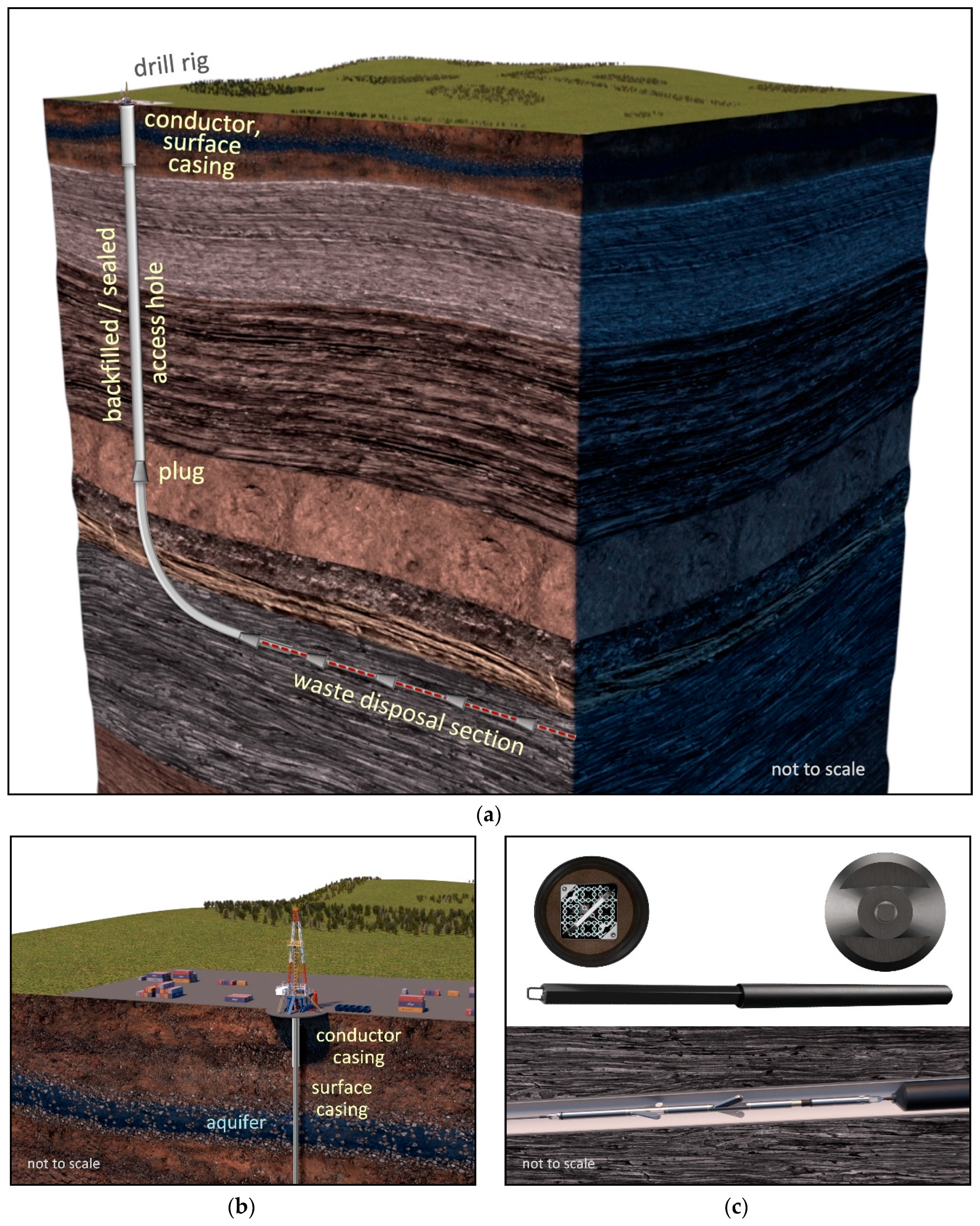
2. Deep Horizontal Drillhole Disposal Concept

2.1. Radioisotope Inventory

We begin the description of the repository concept with some general remarks about the waste that needs to be disposed, focusing on SNF assemblies. The nuclear fuel pellets inserted into a reactor are made of UO2, with about 96% 238U and 4% 235U. Because of the long half-lives of 238U and 235U (4.5 and 0.7 billion years, respectively), the radioactivity of the fresh fuel rods is low. However, when uranium fissions in the reactor, it splits into two or more fragments, which are typically much more radioactive due to their significantly shorter half-lives. Most of the 235U generates decay products such as 3H, 90Sr, 137Cs, 129I and 99Tc. In addition, some of the 238U is converted by neutron absorption and decay into transuranics such as 239Pu, 240Pu, 241Am and 237Np. Other isotopes are created by the decay of their respective parent radionuclides and their concentrations may actually increase as time passes.
It is worth noting that the radioisotopes with very short half-lives decay quickly and thus cause little long-term concern. In contrast, isotopes with very long half-lives (such as 238U and 235U) decay so slowly that they have low radioactivity. Therefore, isotopes with intermediate half-lives (such as 137Cs and 90Sr) are the ones that are difficult to handle and that present disposal challenges. These fission fragments cause the high intensity of the SNF’s initial radioactivity; later, after the first few centuries, the transuranics contribute most to the long-lived radioactivity.
The initial isotope inventory of the nuclear waste to be disposed in a geologic repository is a key determinant of the overall risk. The abundance of each isotope, its half-life and that of its daughter products along the decay chain determine the radioactivity and toxicity of the waste. However, the key performance measure of a repository is not the waste inventory in the canisters but the dose received by a reasonably maximally exposed individual at the surface. This means that the release of isotopes from the waste containers and their transport through the engineered and natural barrier systems to the accessible environment have to be accounted for. The mobility of radioelements is influenced by many factors (such as the flow of liquids and gases, the radioelement’s solubility, adsorption behavior, diffusivity and volatility). These are properties of both the radioelements themselves as well as the man-made and geologic materials through which they migrate. Consequently, the importance of a given radionuclide for nuclear waste disposal is the product of its abundance and an index that accounts for all factors governing the fate of the radionuclide from the waste canister to the affected individual [28]. These importance factors can only be determined by a comprehensive performance assessment analysis, which requires detailed design information and site-specific characterization data. Nevertheless, it is important to have a detailed waste inventory available as input to such an assessment; the inventory developed for the Yucca Mountain project [29] is thus pertinent for a drillhole repository in the United States.
Although the spent fuel from a commercial nuclear reactor could be repackaged or reprocessed, we assume that it remains in the same assemblies that held it in the nuclear reactor, where they are handled as a unit. An assembly typically spends 3 to 5 years in the reactor, after which it is replaced with an assembly containing fresh fuel. During refueling, the reactor is shut down, the lid of the reactor is opened and the fuel assemblies are individually moved to a cooling pool. Despite the chain reaction having been stopped, the removed fuel assembly initially produces heat that is almost 7% of the heat production during reactor operation. This initially high thermal output declines rapidly as the short-lived radioisotopes decay. After ten minutes, it has been reduced to 2% of the operating power and after a day to about 0.5%. As more of the radionuclides decay, the heat production decreases further; after 1 year it is about 10 kW per ton of spent nuclear fuel; after 10 years, it is about 3 kW per ton. The impact of heat generation on repository performance is discussed in Section 3.5.

2.2. Drillhole Repository Configuration

The overall configuration of a horizontal drillhole repository has been schematically presented in Figure 1 above. A vertical access hole is drilled and cased from the surface through confining geologic units to a kickoff point a few hundred meters above the target repository horizon. The purpose of the conductor and surface casings are, respectively, to guide the drilling and to protect freshwater aquifers, schematically shown in Figure 1b. In the horizontal disposal section, the casing facilitates the emplacement (and potential retrieval) of the canisters and supports backfilling operations. A smaller-diameter hole is gradually curved, with a build angle of less than 0.25° per meter (8° per 100 feet), until it is horizontal. The radius of curvature is large enough to avoid any impedance during casing installation and waste emplacement. A third set of casing is installed and cemented in place and then yet a smaller diameter drillhole continues near-horizontally for a few hundred meters to several kilometers. This part of the drillhole is the waste disposal section of the repository, having a minimal diameter as shown in Table 1 to accommodate the canister size designated for a given drillhole. Drilling technology has advanced to the point where rotary steerable systems have high precision with absolute and relative accuracy of less than 1 m.
As the hole is being drilled, rock cores, fluid samples and formation evaluation well logs are collected to aid in site characterization and emplacement decisions. For larger-diameter canisters, the horizontal section may be drilled in two stages: a first small-diameter stage for evaluation and testing of the disposal section followed by a reaming operation to create a diameter large enough to house the canisters.
Once the horizontal section is drilled, another string of casing is cemented in place, potentially with monitoring systems embedded on or in the casing that communicate real-time data about the repository condition to the surface. The continuous casing in the curved and horizontal section of the drillhole facilitates the emplacement (and potential retrieval) of the canisters and supports backfilling operations. Moreover, the casing and the surrounding cement act as additional engineered barriers during the early periods after waste emplacement, providing mechanical protection and preventing fluid flow around the canisters during the initial equilibration phase. The casing also effectively redistributes heat, reducing temperature gradients and associated thermal stresses.
Several drillholes may be completed from the same surface pad, either using separate vertical access holes or possibly by drilling multiple laterals (potentially at different depths) from a single access hole. Modular drillhole repositories could be constructed at or near the sites where the waste is currently in interim storage, minimizing or even avoiding the need for waste transportation outside the boundaries of the nuclear facility. Alternatively, larger, regional repositories could be built if considered appropriate for technical reasons or if otherwise preferred.
The nominally horizontal repository section may have a slight tilt. Such a tilt of a few degrees may be beneficial in keeping fluids and dissolved radionuclides from migrating towards the vertical access hole by inducing density- or buoyancy-driven fluid gradients towards the dead-end of the drillhole.

2.3. Waste Emplacement

To prepare for disposal in a drillhole, the assemblies will be removed from cooling pools or temporary dry storage casks and each one placed in a canister made of a corrosion-resistant alloy. To simplify the transfer of SNF from dry casks to permanent disposal, a new cask storage design could be developed, in which fuel assemblies sitting in the cooling pools are directly loaded into disposal canisters, before being placed into a concrete cask for dry storage.
The canisters are sealed and transported to the drill rig. These operations require radiation shielding by using a transport cask or a modified dry cask system. The canisters are then lowered into the casing, then pushed by a wireline tractor, coiled tubing or drill pipe [30,31] into the horizontal drillhole and released once the disposal location is reached. Canisters may be emplaced one-by-one or in strings of multiple canisters to reduce round-trip time.
In the event of a canister breaking free from its support cable and falling into the vertical access hole, there are several mitigating measures that can be devised to reduce or prevent damage to the canister or casing. The falling canister’s terminal velocity is limited by the presence of water, brine or other viscous fluids present in the casing. For a heavy canister, however, that velocity might be high enough to allow the canister to reach a speed which presents danger to the integrity of the canister, specifically if it hits another canister that had previously been put in place. The maximum velocity can be substantially reduced by self-deploying breaking devices, such as an expandable centralizer, a parachute mechanism or the use of foams. Damage from a collision can also be mitigated by the use of an impact absorber placed on the front end of the canister [32]. Should a canister be damaged, a procedure has to be in place to de-contaminate the drillhole and associated equipment.
Another emplacement risk is that a canister may get jammed or otherwise stuck above the disposal section due to the casing’s tortuosity or other irregularities or obstructions. The large radius of curvature and the precision of current rotary steerable drilling technology make the risk of canister sticking or jamming during the emplacement process very low. However, to further mitigate this risk, a caliper or dummy canister can be lowered into the drillhole to ensure that the casing is free of obstacles and that the emplacement equipment functions as intended. Tools and procedures to retrieve a stuck canister from the drillhole have been routinely used for oil and gas operations and can be enhanced for nuclear disposal operations.

2.4. Retrievability

Many countries require that nuclear waste be retrievable after placement in a repository. (In current U.S. law, this is regulated in 10 CFR 60.111, requiring retrievability for “up to 50 years after the waste emplacement operations are initiated” or “until the completion of a performance confirmation program”.) Retrievability was mandated, in part, because of the possibility that a better disposal method or site might later be found or that the nuclear waste could have value in the future (e.g., as fuel for next-generation nuclear reactors).
To facilitate canister recovery, one option would be to leave the vertical access drillhole open for the first 50 years. Note, however, that sealing of the hole does not preclude recovery, as plugged boreholes can be reopened. In the drilling industry, recovery of objects in a deep drillhole is consid­ered routine using “fishing” technology [33]. Placement and retrieval of borehole equipment are highly developed in the oil industry and are commonly performed using an array of specialized tools and methods.
On 15 November 2018, we placed a dummy canister in a 690 m deep horizontal drillhole, released it, withdrew the placement cable and several hours later inserted a recovery cable, latched the canister and brought it back to the surface. This test was carried out under contract by a drilling company at a previously drilled horizontal borehole. The procedure was repeated on 16 January 2019 as a demonstration [34].
The size and weight of the dummy canister used in the test was designed to represent a canister holding a Cs/Sr capsule. The canister was attached to a hanger, which had a releasable connector; the hanger was coupled to a tractor whose electrically-driven retractable wheels firmly pushed against the casing. The tractor was linked to the surface with a wireline cable. The canister was lowered in the vertical section to the kickoff depth at 242 m, where the hole gradually turned horizontal at a depth of 690 m. The tractor pushed the canister 122 m into the horizontal section. The canister and hanger were released and the wireline cable and tractor pulled to the surface. Subsequently, a special latching mechanism was attached to the tractor and the assembly lowered and pushed back into the horizontal section. The latching device engaged the canister-hanger combination and the canister was retrieved to the surface.
Although this initial demonstration was successful, retrievability of canisters from the disposal section needs to be further examined for the larger SNF canisters and for conditions prevalent in a backfilled, heated, potentially sealed disposal section. A comprehensive bibliography of reports discussing retrievability is available from the Nuclear Energy Agency (NEA) [35].

2.5. Canister and Casing

The canister holding the spent nuclear fuel assemblies or other high-level radioactive waste is a key component of the engineered barrier system. The canister directly protects the waste from mechanical impact, exposure to the chemical environment and contact with fluids, which may dissolve the waste and act as the main transport vehicles for radionuclide migration. While radionuclides released from a breached canister (at early times) will very likely remain contained within the multi-barrier repository system, it is obviously desirable to use canisters with long-time durability. We propose to fabricate canisters made of highly corrosion-resistant nickel-chromium-molybdenum (Ni-Cr-Mo) alloys, such as Alloy 22 (UNS N0622) [36] and Alloy 625 (UNS N06625) [37], which are very stable in the expected hot, reducing chloride environments representative of the deep drillhole disposal sections. Elevated temperatures affect the corrosion behavior of the canister, because they impact both corrosion resistance of the metals and corrosivity of the environment. In the passive state, metals are protected by a thin, self-forming film on the surface, leading to very low general corrosion rates (on the order of 0.01 μm/y). A canister made with Alloy 625 with a wall thickness of 1 cm takes at least 50,000 years to degrade by general corrosion [38].
Localized corrosion mechanisms, which are a particular threat to the durability of passive films, need to be accounted for when predicting the lifetime of a canister [39]. The Ni-Cr-Mo alloys, with their durable, protective (passive) films that are self-forming even in harsh environments, have robust resistance to the localized corrosion processes of pitting, crevice corrosion and stress corrosion cracking [40,41,42,43]. Passive films on Ni-Cr-Mo alloys are highly durable because of a combination of resistance to film breakdown even in highly aggressive environments and their ability to reform (repassivate) after being damaged. Microbially-induced corrosion (MIC) is another potential damage mode to canisters. Alloy 22 is not only one of the most resistant alloys for abiotic corrosion mechanisms but also among the most resistant to MIC [44]. The MIC resistance of Alloy 22 and titanium alloys has been examined under a range of conditions with no evidence of surface damage [45]. Galvanic corrosion is an additional damage mode to be considered and its effects will depend upon the other metals incorporated in the repository, the relative surface areas and the conductivity of filler materials and pore waters.
Mechanical breaching of the canister, for example by puncturing during handling and emplacement or shearing during seismic events or crushing by rock consolidation or volcanism, should also be considered. These risks are mitigated to some extent by the strength of the canister wall.
Calculations for carbon steel casings indicate that their lifetime in a reducing environment can reach several hundred years [38]. This is long enough to provide a reliable and relatively smooth conduit for canister retrieval, should that become necessary or worthwhile. While casings are not designed for long-term waste protection, it is beneficial to have a barrier restricting fluid flow during the early pressure equilibration and thermal periods.
The corrosion of the canisters and casing forms metal oxides and generates hydrogen gas. Both processes lead to volume expansion and, consequently, pressure increases, which in turn induce fluid flow. The use of corrosion-resistant materials leads to a slow generation of corrosion products (hydrogen and oxides). Outside the containment, the slow gas generation allows most of the hydrogen to dissolve in the liquid and diffuse away, that is, reducing or avoiding the emergence of a free gas phase [46]. Moreover, generating corrosion products from a linearly spread-out source expedites radial diffusion and dissipa­tion of the pressure perturbation.

2.6. Backfilling and Sealing

Open space within the canister, between the canister and the casing, the casing and the drillhole wall, as well as along the vertical and curved access sections of the drillhole will be backfilled. The repository may be further sealed by plugs. One of the potential pathways along which radionuclides may migrate to the accessible environment is through advective transport along the drillhole and the excavation disturbed zone around it. Backfilling and sealing these preferential pathways are thus of primary importance.
Each backfill material will be designed for a particular purpose or specific barrier function. In general, low hydraulic conductivity, durability and self-healing abilities are among the main desirable characteristics of a backfill material. However, the choice of material is limited by the engineering challenges of installing the backfill in a small-diameter, deep drillhole. Backfill and sealing methods considered in the deep borehole disposal reference design are described in detail in References [22,47].
As mentioned above, the annulus between the casing and the drillhole wall should be filled using cementitious materials with formulations currently used by the hydrocarbon and geothermal energy industries. Cementing is important to stabilize the casing during canister emplacement and to keep the casing centralized, which is necessary to reduce thermal stresses. Using fine-grained cements and other permeation grouts also helps seal the excavation disturbed zone.
Open space inside the canister can be filled with a suitable material that provides additional safety against mechanical damage from impact and vibration during emplacement or an earthquake and to increase thermal conductivity for more efficient heat dissipation. This filler could also include boron to absorb neutrons and lower the risk of reaching criticality (see Section 3.9).
Once emplaced in the disposal section, backfilling the space between the canisters and the casing serves multiple purposes, including providing stability and mechanical protection, increased heat conduction, reduced fluid flow and, therefore, reduced advective transport of leaked radio­nuclides. It also helps to control the chemical environment, inhibiting corrosion and increasing the adsorption of radionuclides.
Compacted, expandable bentonite is the backfill material of choice in most mined repositories located in the saturated zone (for a review, see Selling and Leupin [48]). However, the excellent barrier properties of bentonite can only be realized if installed under unsaturated conditions, allowing the clay to expand as it hydrates. In a deep drillhole, installation of dry granular bentonite or bentonite blocks is infeasible. Nevertheless, the use of a high-density bentonite suspension is a possibility to be considered. The requirement for pumpability limits the options to materials that set, gel, solidify or swell after emplacement, either driven by a chemical process, temperature changes or mechanical compaction, which induces creep flow or visco-plastic deformations. Such backfills include cementitious materials, oil-based materials (such as tar, bitumen or asphalt), pumpable colloidal silica and other grout mixtures, salts or fine pellets of lead-based alloys that melt and re-solidify to encapsulate the canisters [49]. A detailed research and engineering program could help select or adapt these materials to the chemical, thermal and stress environment at the repository site. Moreover, verifiable methods will be needed to install the backfill material in a small-diameter drillhole and to examine its as-built performance.
When canister emplacement is complete and all initial performance confirmation tests yield satisfactory results, the disposal section is plugged, and the vertical access hole is backfilled and sealed. Effective plugs may be installed by reaming the drillhole over a relatively short section, which is preferably located adjacent to a clay, shale or salt rock layer. The reamed drillhole section will be filled with a suitable backfill material, which will be compacted by the overburden and plastic deformation of the surrounding rock [50,51], effectively isolating the disposal section from the surface and at the same time sealing the excavation disturbed zone. Similar plugs may be installed throughout the disposal section to compartmentalize the disposal section, reducing the risk of axial radionuclide transport to transmissive zones that may intersect the drillhole. In the sections of the vertical hole that penetrate deformable formations, the casing or liner may be removed after waste emplacement to promote self-sealing. Rock welding with resistance heaters and ceramic plugs have also been proposed [52]. The as-built effectiveness of a plug may be confirmed by performing an in-situ pressure test [53]. However, the long-term stability is difficult to assess; multiple plugs may be installed along the drillhole for redundancy.
Backfilling of the disposal, curved and vertical sections of the drillhole provides an opportunity to add sorption-enhancing amendments that retard radionuclide transport; a similar concept has been proposed for the invert in the emplacement tunnels at Yucca Mountain [54]. Backfilling and plugging might increase costs but should not compromise the ability to retrieve waste canisters. Finally, the sealing procedure has to account for the incorporation of sensors that may be installed for performance confirmation.

3. Expected Repository Performance

3.1. Basis of Performance Evaluation

Nuclear waste disposal in deep horizontal drillholes is a novel concept. While work on the detailed repository design and performance assessment is ongoing, an initial evaluation of the expected repository performance builds on the extensive research, analyses, developments and experiences of many organizations throughout the world that develop high-level nuclear waste repositories (for a review, see Faybishenko et al. [55]). Of particular significance is the work that has been performed to assess the performance of mined repositories in a reducing, fully saturated environment—specifically those located in argillaceous host rocks—as well as deep vertical borehole disposal concepts. Complete performance assessments are available for mined repository concepts; a generic safety case for a deep borehole disposal scenario is presented in Reference [56]. The following subsections discuss some performance aspects on a general level, with specifics being addressed in the cited references and upcoming publications.

3.2. Leakage Pathways

The performance of a nuclear waste repository is ultimately measured by the exposure risk to individuals. Evaluating this risk requires a deterministic or probabilistic assessment of the fate and transport of radionuclides from the waste form in the repository along some leakage pathway to the receptor. This pathway is part of several subdomains referred to as (1) the engineered barrier system (EBS), which includes the waste, canister, backfill and other engineered components, such as liners and seals, (2) the geosphere, also referred to as the far field or natural barrier system, which includes the host rock and aquifers and (3) the biosphere, which is the biological environment that determines the radiation dose to the receptor [57]. Special consideration is given to the interface between the EBS and the geosphere, which consists of the damaged or disturbed zone around the excavation [58].
It is essentially impossible to anticipate all potential failure modes and leakage pathways and to determine their probability, characterize the relevant properties and predict the consequences over the entire performance period. Inserting redundancies into a multi-barrier system and making realistically conservative assumptions in the performance assessment calculations are safeguards used against the inherent uncertainties and unidentifiable variabilities of a complex repository system. In this overview, we mention just a few leakage pathways that need to be considered when evaluating the performance of a deep horizontal drillhole repository.
In Section 2.5, we briefly mentioned the role that the canisters play in protecting the waste during the initial, critical period after emplacement up to about 50,000 years [38]. After a breach of the canister (either by corrosion or mechanical destruction, for example, during earthquake-induced fault reactivation), radionuclides dissolve into the resident brine and are released to the near field either by diffusion or advective and dispersive transport. This sequence of processes constitutes the so-called source term. The release rate from the canister may be limited by the solubility or the diffusivity of the radionuclide, along with the geometry of the canister perforation. The reducing conditions encountered in a deep, saturated formation tend to lower the solubility of most radionuclides, leading to smaller release rates and thus lower contaminant concentrations.
Once released from the canister, the radionuclides start migrating (either by advection or diffusion) within and across the engineered barrier system. Given the low permeability of the host rock, radionuclides may preferentially be transported in axial direction along the drillhole. Transport velocity is expected to be very low, mainly because of (1) the presence of low-permeable, absorbing backfill material, (2) plugs installed to prevent axial flow towards and within the vertical access hole and (3) the absence of significant driving forces. The last point deserves additional comments. Potential driving forces within the drillholes are either created by the repository itself or imposed by the natural system. Gradients induced by the repository include differences in chemical potential driving molecular diffusion, pressure perturbations caused by the decay heat (i.e., thermal expansion and contraction of fluids and the pore space during the heat pulse), pressure increases caused by corrosion (i.e., volume increase due to the generation of metal oxides and hydrogen gas) and general equilibration of drilling- and emplacement-induced pressure perturbations. All of these forces are expected to be minor, limited in time (from less than a year to a few centuries) and acting axially over the restricted cross-sectional area of the small-diameter drillhole. Consequently, radionuclide mass flow rates along the drillhole are expected to be very small.
Gradients in the natural system include (1) regional pressure differences caused by topography and recharge patterns, (2) thermal upwelling or convection cells, (3) pressure perturbations induced by stress redistribution (e.g., after an earthquake, volcanic eruption or due to erosion, uplift or glacial loading) and (4) the development of osmotic pressures across rocks with high clay content. Most of these gradients are expected to be small or they develop—and dissipate—slowly over geologic time. Notable exceptions are earthquakes and volcanism. Such disruptive events may generate new faults or magmatic intrusions or reactivate old faults. These discrete features may directly intersect the drillhole and impact the integrity of the engineered barrier system. At the same time, they provide potential pathways for fluid flow and radionuclide transport. Also note that seismic and igneous events may impact pressure gradients even if they occur at a considerable distance from the repository.
Finally, pressure gradients may be generated by human activity, specifically by nearby hydro­carbon production or by large-scale geologic carbon sequestration and energy storage projects.
The migration of volatile radionuclide-containing species such as 14CO2 can occur in near-surface repositories located in the unsaturated zone [59,60]. However, this is very unlikely in the case of a deep drillhole repository located within the saturated zone, where high fluid pressures inhibit the generation of a free gas phase and its migration through the rock.
A site- and disposal hole-specific hydrogeological characterization of the host rock as well as the overlying confining units will determine the properties of the heterogeneous formations, specifically their ability to transmit water in response to the local and regional pressure gradients discussed above. Particular attention needs to be paid to the geometric and hydrological characteristics of faults, deformation zones, contacts between hydrostratigraphic units and fracture networks. Nevertheless, the relatively great target depth (>1 km) of the horizontal drillhole repository makes it unlikely that long, continuous natural pathways exist or are created, or that they have sufficient permeability, cross-sectional area and sustained driving forces to induce significant upward flow rates over long time periods. Radioelement retention properties, such as adsorption onto mineral surfaces and diffusion into stagnant pore water in the surrounding rock matrix, would retard their transport to the accessible environment. Finally, the fact that nuclear waste emplacement is decentralized and stretched out linearly in multiple drillholes (rather than placed with high density at a centralized location) significantly decreases the amount of waste potentially affected by a disruptive event.
For disposal sections located in competent rock of low matrix permeability, molecular diffusion of dissolved radionuclides is the only remaining transport mechanism. Diffusion is driven by chemical-potential gradients, which decrease substantially at even short distances from the disposal drillhole. The small porosity and tortuosity of the pore space considerably reduce the effective diffusivity compared to that in free water, that is, radionuclide migration velocities are very small. Diffusing radionuclides reach very low concentrations after short distances as they are diluted and spread over a radially or even spherically increasing volume of pore water.
Initial calculations lead us to believe that the assessments comprising the safety case will likely demonstrate that these features and effects have either very low probabilities of occurrence or low consequences or that they do not compromise the safety of the repository even when making conservative assumptions and accounting for inherent and irreducible uncertainties. The horizontal drillhole disposal concept takes advantage of geological formations with sufficiently high barrier performance, integrated into a robust disposal system with multiple engineered barriers. Similar screening decisions as the ones presented here have been made previously based on a generic analysis of features, events and processes (FEPs) [61].

3.3. Isolation of Brines from Aquifers

The disposal section of the horizontal drillhole repository is to be located in a deep formation whose pore space would most likely be saturated with brine. Demonstrating that such a brine has been isolated at depth for long time periods is a key factor in assessing the long-term security of the repository. Establishing the absolute age of brines is complicated by mixing processes and the lack of an ideal chronologic marker in the water. However, various isotopic systems can help place limits on age and mixing rates.
In addition to numerical modeling, a good indicator of isolation could be determined by measuring the presence of radioisotopes such as 81Kr. 81Kr is a rare gas formed by cosmic ray interactions in the atmosphere and then incorporated into surface waters. Since it has minimal interaction with local rock and is not generated at depth in significant amounts, it can provide a direct measurement of the isolation of deep brines from surface waters. The presence of measurable 81Kr (with a half-life of 229,000 years) in repository brines indicates that significant amounts of surface water are interacting with or replacing brines on a time scale less than one million years. Conversely, the absence of 81Kr in brines suggests isolation of the brines over similar time scales. Concentrations of 81Kr are extremely small (hundreds of atoms per liter); however, a laser-based resonance ionization technique measures this isotope with sufficient sensitivity [62,63]. Note that low mixing of surface water with deep brines does not directly demonstrate that there is equally slow transport upward.
Upward flow limits can be estimated by measurements of other isotopes, specifically 36Cl and 129I, as a function of depth. These can be measured in deep brines from about one liter of sampled fluid using AMS (accelerator mass spectrometry) [64]. These radioisotopes are produced naturally underground through the decay of uranium and thorium in the rock strata. In the absence of significant flow, each isotope maintains a natural background concentration in the rock that balances production and decay, a pseudo-steady state referred to as secular equilibrium. It takes approximately 4 to 5 half-lives for the system to reach this stable background concentration. These values can be predicted based on the measured rock composition and calculated or measured neutron fluxes from samples [65,66]. Successive layers of rock strata that maintain distinct and different secular equilibrium concentrations of these radioisotopes indicate limited upward flow [67]. We focus here primarily on 36Cl, which has a half-life of 300,000 years and 129I, which has a half-life of 16 million years. Maintenance of unique 36Cl secular equilibrium concentrations can place limits on upward flow of Cl through the rock strata on time frames on the order of one million years. As a simple example, if an overlying formation has a lower value of 36Cl or 129I than does an underlying layer, that suggests absence of significant upward flow of these isotopes.
Helium gas analysis offers another independent means to assess upward flow. 4He, the stable isotope of helium, is emitted in alpha decay. The balance of production and escape of 4He from the rock strata determines the residence time of helium in the rock. 4He gas is quite mobile; estimates of residence times for 4He on the order of 100,000 years and greater suggest that other less mobile species in brines should not escape the rock strata over similar or even much longer time frames [68].
In all of these isotopic studies, care must be taken to keep samples pristine. Small amounts of contamination from field sampling or handling in the laboratory can yield inaccurate and misleading results. Despite inherent difficulties, successful measurements of these isotopes in diverse settings and field conditions are now routinely undertaken.
In addition to isotopic methods, the confining properties of the overburden may be demon­strated by the presence of trapped gas in layers above repository strata. If it is determined that the natural gas was formed over millions of years earlier, then the existence of such gas provides strong evidence that the brine in deeper layers is not flowing upwards.

3.4. Reducing Environment
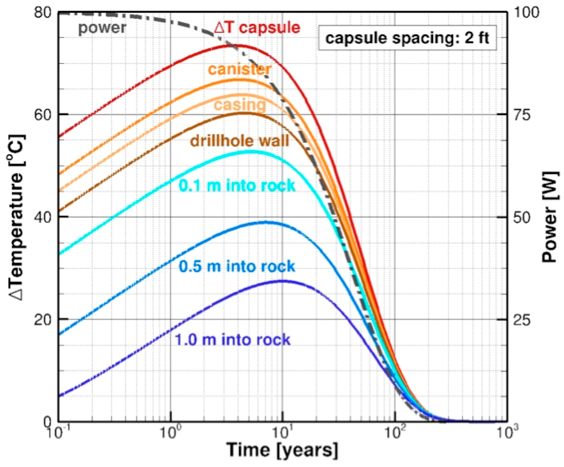
As mentioned above, the reducing environment encountered at repository depth is beneficial for the longevity of the waste canisters and casing. In addition, it affects the solubility and, therefore, the mobility of radionuclides in the subsurface.
In the event a canister is breached and the spent nuclear fuel is exposed to the saline fluids present in the host rock, the constituents of the waste can react with the brine and form new compounds of varying solubility. The subsequent advective and diffusive migration of dissolved radionuclides is dependent on their chemistry, that of the host rock and the dissolved constituents in the brine. Furthermore, most of these factors depend on temperature, alkalinity and redox potential.
The chemical factors that influence radionuclide migration can be divided into two groups, namely (1) those that immobilize the radionuclide by adsorption, ion exchange or mineral (co-)precipitation and (2) those that govern complexing of cationic radionuclides with anions dissolved in the brine, which may enhance their solubility and thus make them amenable to transport.
The valence state of several radionuclides depends on the ambient oxidation state, which in turn substantially affects their chemical properties and ability to migrate in pore fluids. The processes mentioned above are interlinked and in competition. Consequently, a prediction of the actual migration of a radionuclide requires integrating the critical thermodynamic and kinetic parameters affecting its solubility, which needs to be carefully examined by means of reactive transport modeling and, if necessary, supported with additional experiments.

3.5. Decay Heat

The temperature evolution in and around a drillhole containing heat-generating high-level radioactive waste is an important factor impacting repository performance. It affects corrosion rates, barrier properties of backfill materials, degradation of concrete, fluid density and viscosity, radionuclide solubilities, the evolution of the excavation disturbed zone and biogeochemical reactions; in summary, temperature is a key driver of many coupled processes.
The radiation from the spent nuclear fuel is converted to heat in the waste, the engineered barriers and the rock. The decay heat for Cs/Sr waste is initially up to 400 W per capsule [5], decreasing with a half-life of about 30 years. The decay heat for spent nuclear fuel depends on the initial enrichment, burnup percentage and duration of post-reactor cooling. An initial value for spent nuclear fuel is on the order of 10 kW per metric ton of heavy metal (MTHM) [19], decreasing with time as the initial radionuclide inventory and its daughter products decay, as shown in Figure 2 for SNF from a PWR reactor.
The temperature of the canister and the surrounding rock initially rises before declining as radioactivity decreases and as the rock conducts heat away. As an example, Figure 3 shows the temperature evolution around a drillhole holding Cs/Sr capsules that are emplaced with a 2-feet (0.6 m) spacing between them. The initial heat output is 100 W; the temperature change, ΔT, shown in Figure 3 can be linearly scaled to different initial heat output values and can be converted to absolute values by adding the ambient temperature of the host rock. Although the maximum temperature (reached after about 3 years) is above the boiling point of water at atmospheric conditions, it is well below the boiling point for water at a depth of 1.0 km below the water table, which is about 310 °C. These simulations are described in detail by Finsterle et al. [69]; similar studies for Cs/Sr capsules in water, air and deep vertical boreholes are presented by Arnold et al. [47].
These analyses suggest that the linear arrangement of waste canisters with relatively low energy density combined with an approximately cylindrical heat dissipation regime decreases the risk of excessive temperature perturbations, both within the disposal section of the drillhole and the adjacent host rock. Given that the drillhole is filled with water during all stages of the repository’s lifetime (including the operation and post-closure phases), boiling is suppressed by the high hydrostatic pressure, drastically reducing the adverse effects of steam on repository components and lowering the complexity of predicting the overall system behavior.

3.6. Earthquakes

The following two effects of earthquakes on the integrity of the drillhole repository are consid­ered: (1) potential damage to the engineered barrier system and (2) the creation of new pathways for radionuclides to reach the accessible environment.
The potential damage to a canister from earthquake vibrations is small. The only examples of vibration-induced borehole damage occur in highly unconsolidated sediments, which are not suitable for a repository. Near the surface, accelerations of earthquakes rarely exceed 1 g, where g is the gravitational acceleration; below the surface, accelerations are considerably smaller [70,71]. At early times, the casing and cement also substantially attenuate earthquake vibrations due to the elastic impedance contrasts between the rock, the cement and the casing. An added measure of protection from vibrational damage comes from the disposal assembly itself. The fuel rods are held within the canister by the structure of the fuel assemblies and the filling material, and the canisters are embedded in their respective backfill materials and a cemented-in casing.
There is the possibility that one or several canisters will be sheared by a new fault or by reactivation of an existing fault. The probability of a fault actually intersecting the repository is very low and can be further reduced through site and drillhole characterization methods and by orienting the drillholes sub-parallel to the direction of existing faults, so that the shear stress is unlikely to create a new fault that crosses the drillhole. A standoff distance of 100 m from an active fault is sufficient to mitigate the risk of damage to the drillhole. Moreover, for most types of rock, the ductility of the canister is greater than that of the rock and for small fault offsets, the canister would rotate or deform rather than rupture. For some rocks, such as granite, shearing may occur, albeit only affecting a very small number of canisters, even though secondary fracturing and faulting may extend to a distance on the order of 100 m perpendicular to the main fault plane.
Finally, as mentioned in Section 3.2, the creation or reactivation of a fault or associated fracture zone might also create new pathways for fluid flow and radionuclide transport, along with earthquake-induced pressure perturbations acting as the driving force. It should be noted, however, that many faults are not water conducting and the induced pressure gradients are transient.
While strong earthquakes lead to high accelerations and substantial rupturing at and near the land surface, these effects decline with depth, where rock strength increases and no surface wave exists, limiting the impact of earthquakes on the engineered barrier system in a deep drillhole. Moreover, a modular, decentralized waste disposal concept reduces the risk that a large number of canisters are breached in a single event.

3.7. Criticality

The risk of criticality arises if spent fuel undergoes a sustained chain reaction, which could be initiated by the intrusion of water that acts as a neutron moderator. There is no danger of criticality for the Cs/Sr waste, which is very low in 235U or 239Pu content. Estimating the probability of SNF reaching criticality will require the use of computer simulations [72,73]. It can be noted, however, that the spent fuel rods are low in 235U or 239Pu—the very reason why they were removed from the reactor. They could still deliver energy in an environment in which most neutrons are created by fissions in other fuel rods. However, in a drillhole repository, they are placed in a linear configuration, not side-by-side as in the reactor. The empty space in canisters holding the fuel assemblies will be filled with a sand-like material, reducing the volume of water that may be present. If deemed necessary, neutron absorbers (such as boron) could be added to the filler. Nevertheless, for certain kinds of defense waste, particularly those containing high levels of plutonium, the criticality issue will have to be carefully evaluated.

3.8. Inadvertent Intrusion

Inadvertent intrusion refers to the accidental drilling into a repository during the exploration for water or mineral resources. The deep horizontal drillhole concept offers inherent protection against inadvertent intrusion, mainly because of its location well below potable water resources. Furthermore, the flexibility in siting modular horizontal drillhole repositories allows their placement in regions with no commercially viable natural resources. The probability may be higher in regions that have oil or gas bearing shale at the same geographic location. For the short term, this issue is addressed by the U.S. Nuclear Regulatory Commission (NRC) regulations that require mineral rights be secured at any location where nuclear waste is disposed. Finally, U.S. regulations mandate that a marker be placed above the site to alert future generations of the presence of the repository [74]; the effectiveness of such markers, however, is difficult to demonstrate and the consequences of inadvertent intrusion needs to be evaluated regardless of the efficacy of the markers.

3.9. Terrorist Intrusion

Unlike interim storage in pools or dry casks on or near the land surface, waste disposal in deep repositories provides a geologic barrier that safeguards against a terrorist attempt to obtain spent nuclear fuel. Although the fuel is retrievable, removing even one canister after sealing of the drillhole requires installing a tall rig, removing several hundred meters of drillhole sealant and plugs and operating a specialized system to retrieve each canister. Although this procedure is feasible for a professional service company, it is not inexpensive or quick. Moreover, the retrieved canisters will be radioactive when they come to the surface, requiring terrorists to rig shielding and safety equipment. Removal of radioactive waste from a deep drillhole does not lend itself to a surreptitious terrorist attack.

4. Comparison with Other Repository Concepts

4.1. Mined Repositories

The worldwide predominant waste disposal concept is to construct tunnels and caverns in a suitable host rock (igneous, metamorphic, sedimentary or salt) at a depth between 300 m and 900 m and to emplace specially-designed disposal canisters holding the waste directly in these mined cavities or in short vertical or horizontal deposition holes excavated in the floor or sides of a network of access drifts. For repositories located in the saturated zone, highly compacted bentonite is typically used as the buffer within the deposition holes; access tunnels are backfilled and plugged. Variations of this general repository layout are described by Faybishenko et al. [55].
There are important differences between a mined repository and the proposed deep horizontal drillhole concept, some of which can be summarized as follows:
  • Defense in Depth—The currently proposed mined repositories are relatively shallow (typically 500 m) compared to the intended depth of the horizontal disposal section of a drillhole repository (>1000 m). While suitable host formations can be found at shallow depths (note that these sites would also qualify for horizontal drillhole repositories), the option to explore deeper formations has considerable advantages. It expands the rock volume and number of locations available for potential repository siting. More importantly, it increases isolation of the waste, because (1) the thick overburden with multiple confining layers considerably augments the natural barrier system, (2) the migration distance to the accessible environment (especially drinking-water aquifers) is increased substantially, (3) the rock at depth is more competent and hydrogeological conditions are more stable and less affected by the dynamics of near-surface processes and (4) the likelihood of inadvertent intrusion is considerably smaller. Since long-term safety is one of the main goals of any disposal solution, the ability to rely on the natural barrier system is paramount. Going deeper makes best use of the natural barrier system, which is the essence of geological disposal of nuclear waste.
  • Size and Geometry—The volume of rock that needs to be excavated for a mined repository is substantially larger than that for a drillhole repository. Large-diameter access ramps that are long (due to their slope being limited to a few degrees) or shafts are needed for a mined repository, whereas a small-diameter, vertical or curved access hole is sufficient to reach the waste emplacement horizon. Reducing the diameter of the disposal section increases the stability of the opening. More importantly, it reduces the overall hydrological, chemical and mechanical perturbation of the host rock, specifically the extent of the excavation damaged zone, which is considered a poten­tial pathway for radionuclide leakage. The cross-sectional area available for axial radionuclide transport along the backfilled opening and associated damage zone is also much smaller. Sealing deposition holes, constructing plugs and backfilling large access tunnels is more challenging and less reliable than sealing small-diameter drillholes. Finally, the linear end-to-end emplacement of small-diameter canisters holding individual SNF assemblies leads to a smaller waste density, with beneficial consequences for heat dissipation, corrosion-gas accumulation and diffusion and impacts from canister breaches, earthquakes and volcanism. Lower waste density and higher heat dissipation efficiency allows for waste disposal after short post-reactor cooling times at the surface and immediate site closure (i.e., no need for extended ventilation periods); it also reduces post-closure criticality issues.
  • No Humans Underground—Much of the excavation volume and infrastructure of a mined repository is needed for enabling humans to work underground. This includes drainage and ventilation of the tunnels but also the installation of underground transportation and emergency equipment. Large machinery for excavation and waste emplacement require additional infrastructure. Humans will need to work underground during the construction of the repository, its operation and closure. This requires continued drainage and ventilation of the tunnel system until reposi­tory closure, that is, typically for a few decades. In many cases, ground support systems or liners must be installed. In addition to costs, changing the underground conditions to those needed for human life considerably affects the near field of the repository. Drainage over decades leads to fluid flow in the host rock and depressurization with associated deformations caused by effective stress changes. Ventilation not only leads to dry-out and potential desiccation cracking (in a clay-rich host rock) but introduces oxygen that remains underground until consumed by corrosion and other chemical reactions. While most of these perturbations are limited in time, some may be irreversible and need to be accounted for, complicating performance assessment calculations. While waste emplacement in a mined repository may be accomplished using remote-controlled machinery, the process of doing so is complex and costly. By comparison, constructing a drillhole repository and waste emplacement in the disposal section has minimal impact on the hydrology, geochemistry and stress conditions of the host rock. The perturbations that do occur are of considerably smaller extent and shorter duration. Construction, waste emplacement and site closure activities are simpler and require fewer workers and no underground life support system. These factors contribute to the lower costs of a drillhole repository.
  • Site Characterization—Information and data from site characterization activities are key for site selection and performance assessment calculations and eventual licensing of a repository. While much of the initial characterization is done from the surface (e.g., using geophysical methods) and exploration boreholes drilled proximate to the disposal borehole, humans working in a mined repository have direct access to the host rock for detailed characterization and testing. For a drillhole repository, such direct inspection of the host rock by humans is limited to cores pulled from the drillhole. Nevertheless, testing, mapping and characterizing rock properties from boreholes are off-the-shelf technologies in the hydrocarbon and geothermal industries. Extensive data sets can be obtained from cores, fluid samples, geophysical well logs, borehole videos, caliper logs, hydraulic and compliance testing, in-hole tracer testing, flowing-fluid electric conductivity logging and high-resolution, continuous monitoring of temperatures, deformations and acoustic signals using fiber-optic cables [22]. Sophisticated methods and computational toolsets for analyzing and interpreting borehole data are available. It should also be noted that direct underground observations available in mined repositories are limited to the tunnel surface, which is a very small fraction of the three-dimensional host formation. Moreover, the properties inferred from these observations reflect the excavation disturbed zone (which is much smaller and thus less relevant in a drillhole repository) and they may be biased due to the artificial environment created in the tunnel. For example, ventilation effects bias or render impossible the direct observation of water inflows that would occur under natural conditions. The need to account for such unwanted effects greatly complicates the analysis and interpretation of “direct” observations taken in a mined repository [75,76].
  • Modularity—Mined repositories are typically conceptualized as large, centralized facilities, intended to accommodate all or a considerable fraction of a country’s high-level nuclear waste inventory. For such large projects, site selection, licensing, construction, waste emplacement and site closure are all technically challenging, expensive and time-consuming processes with a considerable risk of failure—for both technical and non-technical reasons. Deep horizontal drillhole repositories are suitable for flexible, modular, decentralized and fast implementation. Finding disposal solutions for a relatively small fraction of the waste (e.g., that produced by a nearby power plant or other nuclear facility) is more tractable. Long-distance transportation of nuclear waste can be reduced or eliminated altogether. Surface facilities are relatively small and the duration of an individual project comparatively short. Customized solutions for special conditions (e.g., small inventories) or special types of waste (e.g., the Cs/Sr capsules) can be found and implemented in a locally optimized, timely manner. We also believe that stakeholders are more amenable to accept a local solution that substantively reduces the risks associated with local interim storage at the surface and long-distance transportation.
Key differences between a mined repository and the deep horizontal drillhole concept are listed in Table 2.
The Yucca Mountain mined repository is unique in that it is located in the unsaturated zone, that is, above the groundwater table. While the previous general comments about mined repositories (and their differences to a deep drillhole repository) also apply to Yucca Mountain, there are some additional features specific to Yucca Mountain that are worth discussing:
  • Unsaturated Zone—The pores of the fractured, volcanic rocks at the Yucca Mountain repository level are only partly filled with water. (Note that aridity was one of the main reasons why Yucca Mountain was selected as a potential disposal site [77]). Even given that the liquid saturation of the tuff matrix is typically above 80% [78], air flows primarily within the fracture network [79,80]. One consequence of ubiquitous airflow is that volatile radionuclides may be transported to the atmosphere [59,60]. However, the main conse­quence of the presence of air convection is that the repository is in an oxidizing environment, substantially affecting water chemistry and its impact on canister corrosion and radionuclide solubility. The considerable benefits of a repository located in a reducing environment have been discussed previously in Section 3.4. Furthermore, a principle of vadose zone hydrology is that water percolates essentially vertically through the fracture system but may be diverted laterally at hydrostratigraphic contacts, perched water bodies and notably around the emplacement drifts, reducing the amount of water that drips into underground openings [81]. Moreover, a shadow zone develops beneath the emplacement drift, suppressing diffusive and advective releases of radionuclides into the near field [82]. These beneficial effects are a direct result of capillary forces, which only occur in unsaturated rocks, that is, they are not active in a saturated zone repository. However, predicting the capillary barrier effect is complex, because flow diversion depends on two-phase parameters that are difficult to determine for fractured porous media [83,84]. Moreover, the amount and distribution of dripping depends on the difficult-to-characterize small-scale roughness of the drift ceiling, which can drastically change after partial drift collapse. Condensation further complicates the prediction of the in-drift environment, specifically during the thermal period. As a consequence, titanium drip shields had to be added to the engineered barrier system to prevent water from dripping directly onto waste packages, and—as a side benefit—to prevent mechanical damage due to rock fall. In summary, the unsaturated zone may be a viable location for a nuclear-waste repository, offering certain benefits. However, it has considerable drawbacks, such as the oxidizing environment and the fact that the vertical downward flow of contaminated water will eventually encounter a near-surface aquifer. Most importantly, unsaturated conditions make the system exceedingly complicated to characterize, analyze, understand, predict and, therefore, defend in a license application; no credit could be taken for many of the benefits mentioned above.
  • Thermal Regime—In the unsaturated zone of Yucca Mountain is near atmospheric pressure conditions, where water boils at a temperature of approximately 96 °C (the boiling temperature may be higher in small rock pores or if a deliquescent brine forms). Evaporation and boiling changes the geochemistry of the near field, with complex impacts on mineralization, adsorption properties and corrosiveness of the waters entering the waste emplacement drifts. It also generates a pressure buildup that induces vapor flow and condensation, which are effective moisture and heat transfer mechanisms. Such coupled thermal-hydrological-geochemical processes have been studied for repository conditions during the thermal period, both experimentally and numerically [85,86,87]. Such analyses are very complicated, specifically because of the two-phase conditions induced by boiling, which make the resulting predictions of repository performance uncertain. By contrast, the hydrostatic pressure in a deep drillhole repository prevents boiling, even under highly elevated temperatures, reducing the impact of spatial variability as well as conceptual and parametric uncertainties on model predictions.
  • Repository Site—It is far beyond the scope of this paper to comprehensively describe and evalu­ate the site-specific aspects of the Yucca Mountain repository. A summary of the natural barrier system and a brief history of the extensive program needed to characterize the site can be found in Rechard et al. [88]. Much of the effort needed is a result of the complexity of: (1) its location in the unsaturated zone near the land surface and above the water table; (2) the geological environment indicating recent seismicity and volcanism; (3) the intricate stratigraphy, consisting of sequences of porous and highly fractured tuffs, some containing lithophysal cavities, intersected by faults, associated with a saturated alluvial formation extending to the compliance boundary; and (4) the engineered barriers and repository concept itself, which had to be adapted to reduce the impact of uncertainties in the expected system behavior. Building a repository in such an environment led to a large number of features, events and processes that needed to be considered [89]. Moreover, addressing the complexity of the coupled processes induced by the heat-generating waste required an extensive research program.
It is expected that a deep horizontal drillhole repository is fundamentally simpler to design, construct and operate. Most importantly, the reduced complexity of a drillhole repository will likely make it easier to demonstrate its immediate and long-term safety. Finally, the modularity of the drillhole concept and the relatively small size of an individual disposal project provide the flexibility to abandon a site should the local conditions turn out to be unsuitable or require costly adaptations.
A comparison of salient features of the Yucca Mountain repository and those for the deep horizontal drillhole concept is shown in Table 3. The Yucca Mountain project was suspended in 2010 after about $15 billion was spent; according to the U.S. Department of Energy, completion would cost over $96 billion (in 2007 dollars) [90].

4.2. Deep Vertical Borehole Disposal

The approach described in this paper was inspired by the DOE deep borehole disposal program; however, it differs in several important aspects. The DOE program considered vertical holes drilled 3 miles (5 km) deep into crystalline basement rock, typically granite, which underlies sedimentary formations. The waste was to be disposed in the bottom 1 to 2 kilometers of the borehole [20,56]. In contrast, the horizontal drillhole method emplaces waste canisters in the horizontal section of a drillhole, deeper than for mined repositories but not as deep as needed for vertical boreholes.
Most of the differences between these two concepts are a direct result of the different orienta­tion of the disposal section:
  • Stratigraphy—The subsurface is predominantly stratified horizontally. (Note that such horizontal stratification is less pronounced in the more monolithic crystalline basement, which is the target host rock of DOE’s deep borehole proposal). Similarly, most relevant conditions (specifically total stress, lithostatic and hydrostatic pressures, temperature and fluid density) are also stratified horizontally. This means that a vertical borehole is likely to traverse many discrete hydrostratigraphic interfaces and encounters constantly varying conditions. By contrast, the horizontal drillhole can be aligned in the principal dimension of the formation and encounter similar thermodynamic conditions and state variables along its length. A notable exception is the probability of intersecting steeply dipping faults, which is higher for a horizontal than a vertical borehole. While deep basement rocks can be thick, the vertical length of the disposal section is restricted by depth limitations, whereas relatively long horizontal disposal sections can be drilled.
  • Vertical Gradients—The fact that pressure, temperature and salinity are relatively uniform in a horizontal drillhole implies that gradients inducing fluid flow and radionuclide transport are relatively small. In a vertical drillhole, decay heat from the high-level waste (superimposed on the natural geothermal gradient) induces thermal convection cells that are aligned with the orientation of the borehole [91], which may be regarded as a preferential flow path that passes through the horizontal, confining layers of the natural barrier system. By contrast, the density differences created by thermal expansion do not induce significant buoyancy-driven flow in a horizontal drillhole. Note that the vertical salinity increase and associated density stratification is beneficial in both the deep vertical disposal concept and the vertical access section of the horizontal drillhole repository. In the former, however, the stratification is disturbed during the thermal period and needs to be reestablished afterwards—a process that also leads to fluid flow. While minor, such gradients and associated flows should be mitigated, as is the case in the horizontal drillhole concept. Finally, the natural geothermal gradient leads to non-uniform and considerably higher ambient temperatures in the disposal section of a vertical borehole repository, with several implications on overall performance.
  • Mechanical Load—The stacking of heavy waste packages in the vertical disposal borehole leads to a considerable accumulated load on the canisters. Detailed stress analyses [23] indicate that safety factors are relatively small, specifically for deep canisters that experience high loads and reduced axial and radial crush resistance because of reduced yield strength at high temperatures. As a precaution, multiple bridge plugs need to be installed to bear the weight of additional waste packages emplaced above. Plugs, however, are considered by some as the weakest link in the vertical borehole approach [8]. Similar issues need to be addressed for the casing and compaction of backfill materials. None of these technical complications apply to canisters arranged horizontally, leading to a simplified performance assessment calculation with fewer scenarios. Moreover, a lighter design can be chosen for the canisters and casing, with added benefits regarding handling, emplacement, retrievability, effects from corrosion products and cost. Finally, the length of the disposal section is not limited by the accumulation of stacking loads.
  • Drilling and Waste Emplacement—The drilling technology developed by the oil, gas and geothermal industries is sufficiently advanced to allow for deep vertical or directional drilling in different geological settings. Drilling costs depend mostly on depth, diameter, casing design and local geologic conditions [92]. Vertical borehole disposal may consider the free-fall method for waste emplacement [23,31], an option not available for a horizontal drillhole repository, where a wireline tractor, coiled tubing or drill pipe is needed to push the canisters into the disposal section. Emplacement risks are discussed in detail in Reference [23].
Borehole disposal repositories with either vertical or horizontal waste disposal sections share many advantages and challenges. Table 4 summarizes some of the differences between the two concepts.

5. Summary and Concluding Remarks

The horizontal drillhole repository concept is presented here as an approach for the disposal of spent nuclear fuel and high-level nuclear waste. It builds on and complements existing repository designs. Its modular design allows it to be used to supplement other methods without the high cost of building a large facility. We consider deep horizontal drillhole disposal a viable concept mainly for the following reasons:
  • Radioactive waste is effectively isolated from the accessible environment by the great depth of the repository and the thick, protective natural barrier system above it—this is the essence of geological waste disposal.
  • The concept is comparatively simple. Complexity is reduced in all aspects related to building and operating the repository, including siting, construction, waste handling, transportation, emplacement, sealing and closure. Most importantly, the inherent simplicity of the concept leads to a more robust and more defensible safety assessment, with markedly fewer, less intricate features, events and processes that need to be examined.
  • The repository has a compact geometry but a locally lower waste density. The small diameter of the disposal drillhole reduces the size of engineered barrier components, simplifying their construction and, consequently, increasing their robustness. The cross-sectional area available for fluid flow and radionuclide transport along the drillhole and excavation disturbed zone is substantially smaller than in a mined repository. The relatively low waste density in the linear drillhole arrangement distributes heat production, decreases the criticality risk and the consequences associated with disruptive events.
  • The concept offers great flexibility, both globally and locally. Drillhole repositories of different sizes can be built in a modular fashion, tailored to the specifics of the waste inventory as well as geographical and geological conditions. In particular, relatively small repositories can be built on the sites where the waste is produced, limiting or avoiding transportation. Locally, the design of the repository can be adapted to the geologic conditions (and other constraints) by changing the number, length, orientation and inclination of the disposal sections. This global and local flexibility allows for a staged approach, with short implementation times and immediate site closure after waste emplacement, reducing overall risks and costs.
  • The simplicity, compactness and flexibility of the drillhole disposal concept also reduce logistical complexity. Specifically, no humans need to be underground, transportation is reduced or avoided and established drilling technology can be used. This reduces the need to build and license additional, complex infrastructure. Logistical simplicity increases operational safety and reduces costs.
The proposed concept faces the following main challenges:
  • In the United States, the absence of a legal framework and uncertainties about the regulatory environment complicate the planning and preparation of a license application for a deep horizontal drillhole repository. In the U.S., the Nuclear Waste Policy Act currently does not allow a second repository for commercial spent nuclear fuel until the Yucca Mountain facility is completed; note that there is no similar restriction for the disposal of defense waste (such as the Cs/Sr capsules). No licensing protocol exists yet for a modular, deep horizontal drillhole repository. While multiple, individual license applications need to be prepared, it is conceivable that these applications would be simpler than that for a large mined repository (due to the relative simplicity of the drillhole concept). Moreover, the parts of the application (e.g., related to drilling and emplacement technologies), which are not related to site-specific conditions, are likely to be transferable between sites. A regulatory perspective for deep borehole disposal is provided by Winterle et al. [93].
  • Characterization by direct inspection of the host rock by humans working underground is not possible in a drillhole concept. However, as discussed in Section 4.1, we believe that the suite of advanced borehole-based coring, logging, testing and characterization methods currently available provide sufficient information about the safety-relevant properties of the host formation. Moreover, the data collected in drained, ventilated, large underground openings are difficult to interpret and may not accurately reflect post-closure repository conditions. Also note that a large component of site characterization (also for mined repositories) consists of surface-based geophysical surveys and geological mapping. Characterization needs may be different for drillhole repositories than mined repositories due to their relative simplicity and reduced perturbation of the host rock by excavation and operation of large underground openings. And finally, drillholes can be visually inspected with remote cameras. (Videos of such inspections are readily available online on YouTube.) To take advantage of such a capability, the hole needs to be filled with a clear fluid for an inspection stage that would take place prior to casing the drillhole and the placement of the canister. Such borehole inspection is common practice in the drilling industry.
  • Scientists, engineers, regulators, stakeholders and the public need to gain confidence in the expected performance and safety of the repository. This is only possible after comprehensive performance assessment studies and a related safety case have been presented. Developing a defensible license application depends—in part—on the legal and regulatory framework, which may need to be adapted to accommodate the deep horizontal drillhole concept. Nevertheless, many aspects of the proposed concept can be based on decades of research, testing, engineering analyses and experiences made worldwide by independent institutions, nuclear waste management organizations, as well as the oil, gas and geothermal industries. Additional technical arguments specifically related to a drillhole repository were presented in Section 3 above.
In this paper, we focused the discussions on the technical aspects of this novel waste disposal concept. For the proposed technology to become a viable solution for the protection of human health and the environment from the long-term effects of spent nuclear fuel and high-level radioactive waste, the regulators and the public must accept it. Engaging these stakeholders throughout the conceptualization, development and implementation of a waste disposal solution is not only essential but also the main goal of the descriptions and discussions presented in this article.

6. Patents

The basic approach is patented by Deep Isolation: U.S. patent 10,002,683 B2. Two other patents have been allowed but not yet issued (as of March 2019); several others have been applied for.

Author Contributions

All authors contributed to the conceptualization presented here, review of the manuscript and editing. Writing was done primarily by R.M. and S.F. Calculations and analyses were performed by R.M., S.F., J.P. and J.A. Project supervision and administration were done by R.M. and E.A.M.

Funding

This research was supported by Deep Isolation Inc.

Acknowledgments

The authors thank the three anonymous reviewers for their comments; they are particularly grateful to P. Swift, D. Sassani and P.V. Brady for their guidance and intellectual support. J. Lamana’s editorial suggestions are greatly appreciated.

Conflicts of Interest

S. Finsterle, J. Rector, J. Payer and J. Apps are paid consultants for Deep Isolation Inc.

References

  1. Forsberg, C.W. Rethinking high-level waste disposal: Separate disposal of high-heat radionuclides (90Sr and 137Cs). Nucl. Technol. 2000, 131, 252–268. [Google Scholar] [CrossRef]
  2. U.S. Energy Information Administration. Available online: https://www.eia.gov/todayinenergy/detail.php?id=24052 (accessed on 4 February 2019).
  3. Staiger, M.D.; Swenson, M.C. Calcined Waste Storage at the Idaho Nuclear Technology and Engineering Center; Report INEEL/EXT-98-00455 Rev 4; Idaho National Lab: Idaho Falls, ID, USA, September 2011; p. 488.
  4. SNL (Sandia National Laboratories). Evaluation of Options for Permanent Geologic Disposal of Spent Nuclear Fuel and High-Level Radioactive Waste in Support of a Comprehensive National Nuclear Fuel Cycle Strategy; SAND2014-0187P (Vol. 1), SAND2014-0189P (Vol. II); Sandia National Laboratories: Albuquerque, NM, USA, 2014; Volumes I and II (Appendices).
  5. Price, L. Overview of Cesium and Strontium Capsules for Deep Borehole Disposal. In Proceedings of the International Meeting on Deep Borehole Disposal of High-Level Radioactive Waste, Sheffield, UK, 13–15 June 2016; Sandia National Laboratories: Albuquerque, NM, USA, 2016. [Google Scholar]
  6. Wagner, J.C.; Peterson, J.L.; Mueller, D.E.; Gehin, J.C.; Worall, A.; Taiwo, T.; Nutt, M.; Williamson, M.A.; Todosow, M.; Wigeland, R.; et al. Categorization of User Nuclear Fuel Inventory in Support of a Comprehensive National Nuclear Fuel Cycle Strategy; Report ORNL/TM-2012/308; Oak Ridge National Laboratory: Oak Ridge, TN, USA, 2012; p. 98.
  7. U.S. Nuclear Regulatory Commission (NRC). Consolidated Interim Storage Facility (CISF). Available online: https://www.nrc.gov/waste/spent-fuel-storage/cis.html (accessed on 26 February 2019).
  8. Sapiie, B.; Driscoll, M.J. A Review of Geology-Related Aspects of Deep Borehole Disposal of Nuclear Wastes; Report MIT-NFC-TR-109; MIT: Cambridge, MA, USA, 2009. [Google Scholar]
  9. Carter, J.T.; Luptak, A.J.; Gastelum, J.; Stockman, C.; Miller, A. Fuel Cycle Potential Waste Inventory for Disposition; Report FCR&D-USED-2010-000031 Rev 5; U.S. Department of Energy: Washington, DC, USA, July 2012.
  10. Baker Hughes, Drilling Services, Directional Drilling Technologies. Available online: https://www.bhge.com/system/files/2018-06/Drilling-Services-pstr.pdf (accessed on 21 February 2019).
  11. Weatherford, Casing Accessories. Available online: https://www.weatherford.com/en/documents/catalog/casing-accessories/ (accessed on 21 February 2019).
  12. National Academy of Sciences (NAS). The Disposal of Radioactive Waste on Land. 1957. Available online: http://www.nap.edu/openbook.php?record_id=10294 (accessed on 4 February 2019).
  13. O’Brien, M.T.; Cohen, L.H.; Narasimhan, T.N.; Simkin, T.L.; Wollenberg, H.A.; Brace, W.F.; Green, S.; Pratt, H.P. The Very Deep Hole Concept: Evaluation of an Alternative for Nuclear Waste Disposal; Report LBL-7089; Lawrence Berkeley Lab.: Berkeley, CA, USA, 1979; p. 47. Available online: https://escholarship.org/uc/item/07m0q8xf (accessed on 4 February 2019).
  14. Woodward-Clyde Consultants. Very Deep Hole Systems Engineering Studies; Woodward-Clyde Consultants: San Francisco, CA, USA, 1981. [Google Scholar]
  15. Juhlin, C.; Sandstedt, H. Storage of Nuclear Waste in Very Deep Boreholes: Feasibility Study and Assessment of Economic Potential; SKB Technical Report 89-39; Svensk Kärnbränslehantering (SKB): Stockholm, Sweden, 1989. [Google Scholar]
  16. Gibb, F.G.G. A new scheme for the very deep geological disposal of high-level radioactive waste. J. Geol. Soc. Lond. 2000, 157, 27–36. [Google Scholar] [CrossRef]
  17. Chapman, N.; Gibb, F. A truly final waste management solution: Is very deep borehole disposal a realistic option for high-level wastes or fissile materials? Radwaste Solut. 2003, 10, 26–37. [Google Scholar]
  18. Logan, S.E. Deep self-burial of radioactive wastes by rock melting capsules. Nucl. Technol. 1974, 21, 111–117. [Google Scholar] [CrossRef]
  19. Ansolabehere, S.; Deutch, J.; Driscoll, M.; Holdren, J.P.; Joskow, P.L.; Lester, R.K.; Moniz, E.J.; Todreas, N.E. The Future of Nuclear Power: An Interdisciplinary MIT Study; Massachusetts Institute of Technology: Cambridge, MA, USA, 2003; ISBN 0-615-12420-8. Available online: http://web.mit.edu/nuclearpower/pdf/nuclearpower-full.pdf (accessed on 22 February 2019).
  20. Brady, P.V.; Arnold, B.W.; Freeze, G.A.; Swift, P.N.; Bauer, S.J.; Kanney, J.L.; Rechard, R.P.; Stein, J.S. Deep Borehole Disposal of High-Level Radioactive Waste; Report SAND2009-4401; Sandia National Laboratories: Albuquerque, NM, USA, 2009; p. 75.
  21. Bates, E.A.; Driscoll, M.J.; Lester, R.K.; Arnold, B.W. Can deep boreholes solve America’s nuclear waste problem? Energy Policy 2014, 72, 186–189. [Google Scholar] [CrossRef]
  22. Arnold, B.W.; Brady, P.V.; Bauer, S.J.; Herrick, C.; Pye, S.; Finger, J. Reference Design and Operations for Deep Borehole Disposal of High-Level Radioactive Waste; Report SAND2011-6749; Sandia National Laboratories: Albuquerque, NM, USA, 2011; Chapter 5.
  23. SNL (Sandia National Laboratories). Deep Borehole Field Test Conceptual Design Report; Report SAND2016-10246R; Sandia National Laboratories: Albuquerque, NM, USA, 2016; p. 212. [CrossRef]
  24. Blue Ribbon Commission on America’s Nuclear Future, Report to the Secretary of Energy, January 2012. Available online: https://www.energy.gov/sites/prod/files/2013/04/f0/brc_finalreport_jan2012.pdf (accessed on 4 February 2019).
  25. Nuclear Waste Technical Review Board (NWTRB). Transcript Fall 2015 Board Meeting; NWTRB: Arlington, VA, USA, 2015. Available online: https://www.nwtrb.gov/docs/default-source/meetings/2015/october/15oct21.pdf (accessed on 22 February 2019).
  26. Nirex. A Review of the Deep Borehole Disposal Concept for Radioactive Waste; Report No. N/108; United Kingdom Nirex Limited: Harwell, UK, 2004. [Google Scholar]
  27. Bracke, G.; Charlier, F.; Liebscher, A.; Schilling, F.R.; Röckel, T. About the possibility of disposal of HLRW in deep boreholes in Germany. Geosciences 2017, 7. [Google Scholar] [CrossRef]
  28. Jarzemba, M.S.; Pickett, D.A. An Evaluation of the Important Radionuclides for Performance Assessment; Center for Nuclear Waste Regulatory Analyses: San Antonio, TX, USA, May 1995; p. 32. [Google Scholar]
  29. Miller, H. Initial Radionuclide Inventories; UCRL-TR-213993, ANL-WIS-MD-000020 Ref 1; Bechtel SAIC Company LLC.: Las Vegas, NV, USA, September 2004; p. 124. [Google Scholar]
  30. Hardin, E.; Jenni, K.; Clark, A.; Cochran, J.; Finger, J.; Sevougian, S.D.; Su, J. Deep Borehole Disposal Waste Emplacement Mode Cost-Risk Study; SAND2015-9775C; Sandia National Laboratories: Albuquerque, NM, USA, 2016; p. 15.
  31. Bates, E.A.; Driscoll, M.J.; Buongiorno, J. Drop-In Concept for Deep Borehole Canister Emplacement. In Proceedings of the 13th International High-Level Radioactive Waste Management Conference, Albuquerque, NM, USA, 10–14 April 2011; American Nuclear Society: Chicago, IL, USA, 2011. [Google Scholar]
  32. Beswick, A.J.; Gibb, F.G.F.; Travis, K.P. Deep borehole disposal of nuclear waste: Engineering challenges. Proc. Inst. Civil Eng. Energy 2014, 167, 47–66. [Google Scholar] [CrossRef]
  33. DeGeare, J.P. The Guide to Oilwell Fishing Operations, 2nd ed.; Gulf Professional Publishing: Houston, TX, USA; Elsevier: Amsterdam, The Netherlands, 2015; p. 234. ISBN 9780124200043. [Google Scholar] [CrossRef]
  34. Conca, J. Can We Drill A Hole Deep Enough for Nuclear Waste? Forbes Magazine. 31 January 2019. Available online: https://www.forbes.com/sites/jamesconca/2019/01/31/can-we-drill-a-hole-deep-enough-for-our-nuclear-waste/#47cbd3a768a7 (accessed on 13 February 2019).
  35. Nuclear Energy Agency (NEA). Selected International Bibliography on Reversibility and Retrievability to Support the Current NEA Project; NEA/RWM11: Vienna, Austria, September 2010; Available online: https://www.oecd-nea.org/rwm/rr/documents/RR_Bibliography.pdf (accessed on 1 March 2019).
  36. Special Metals Corporation. Inconel Alloy 22. Available online: http://www.specialmetals.com/assets/smc/documents/alloys/inconel/inconel-alloy-2.pdf (accessed on 4 April 2019).
  37. Special Metals Corporation. Inconel Alloy 625. Available online: http://www.specialmetals.com/assets/smc/documents/alloys/inconel/inconel-alloy-625.pdf (accessed on 4 April 2019).
  38. Payer, J.; Finsterle, S.; Apps, J.; Muller, R.A. Corrosion performance of engineered barrier system in deep horizontal drillholes. Energies 2019, 12, 1491. [Google Scholar] [CrossRef]
  39. King, F.; Kolář, M. Lifetime predictions for nuclear waste disposal containers. Corrosion 2019, 75, 309–323. [Google Scholar] [CrossRef]
  40. Rebak, R.B. Selection of corrosion resistant materials for nuclear waste repositories. Mater. Sci. Technol. Assoc. Iron Steel Technol. 2006, 6, 639. [Google Scholar] [CrossRef]
  41. Shoesmith, D.W. Assessing the corrosion performance of high-level nuclear waste containers. Corrosion 2006, 62, 703–722. [Google Scholar] [CrossRef]
  42. King, F. Container materials for the storage and disposal of nuclear waste. Corrosion 2013, 69, 986–1011. [Google Scholar] [CrossRef]
  43. Payer, J.H.; Finsterle, S.; Apps, J.A.; Muller, R.A. Corrosion resistant alloy canisters for nuclear waste disposal in horizontal drillholes. In Proceedings of the International High-Level Radioactive Waste Management Conference, Knoxville, TN, USA, 14–18 April 2019. [Google Scholar]
  44. King, F. Microbiologically influenced corrosion of nuclear waste containers. Corrosion 2009, 65, 233–251. [Google Scholar] [CrossRef]
  45. Else, T.A.; Pantle, C.R.; Amy, P.S. Boundaries for biofilm formation: Humidity and temperature. Appl. Environ. Microbiol. 2003, 69, 5006–5010. [Google Scholar] [CrossRef] [PubMed]
  46. Finsterle, S.; Payer, J.; Muller, R.A. Heat Dissipation and Corrosion-Gas Migration Near Spent Nuclear Fuel Canisters Disposed in Deep Horizontal Drillholes. 2019; in preparation. [Google Scholar]
  47. Arnold, B.W.; Brady, P.; Sutton, M.; Travis, K.; MacKinnon, R.; Gibb, F.; Greenberg, H. Deep Borehole Disposal Research: Geological Data Evaluation; Alternative Waste Forms and Borehole Seals; SAND2014-17430R; Sandia National Laboratories: Albuquerque, NM, USA, September 2014; p. 116.
  48. Selling, P.; Leupin, O.X. The use of clay as an engineered barrier in radioactive-waste management—A review. Clays Clay Miner. 2013, 61, 477–498. [Google Scholar] [CrossRef]
  49. Gibb, F.G.F.; Travis, K.P.; McTaggart, N.A.; Burley, D.; Hesketh, K.W. High density support matrices: Key to deep borehole disposal of spent nuclear fuel. J. Nucl. Mater. 2008, 374, 370–377. [Google Scholar] [CrossRef]
  50. Kristiansen, T.G.; Dyngeland, T.; Kinn, S.; Flatebo, R.; Aarseth, N.A. Activating Shale to Form Well Barriers: Theory and Field examples, SPE-191607-MS. In Proceedings of the 2018 SPE Annual Conference and Exhibition, Dallas, TX, USA, 24–26 September 2018. [Google Scholar]
  51. Vrålstad, T.; Saasen, A.; Fjær, E.; Øia, T.; Ytrehus, J.D.; Khalifeh, M. Plug & abandonment of offshore wells: Ensuring long-term well integrity and cost-efficiency. J. Pet. Sci. Eng. 2019, 173, 478–491. [Google Scholar] [CrossRef]
  52. Lowry, W.; Dunn, S.; Coates, K.; Duguid, A.; Wohletz, K. High performance ceramic plugs for borehole sealing. In Proceedings of the 13th International High-Level Radioactive Waste Management Conference, Charleston, SC, USA, 12–16 April 2015; American Nuclear Society: Chicago, IL, USA, 2015; pp. 407–413. [Google Scholar]
  53. Fjær, E.; Stenebråten, J.F.; Bakheim, S. Laboratory Test for Studies on Shale Barrier Formation, ARMA 18-1146. In Proceedings of the 52nd US Rock Mechanics/Geomechanics Symposium, Seattle, WA, USA, 17–20 June 2018. [Google Scholar]
  54. Krumhansl, J.L.; Pless, J.D.; Chwirka, J.B.; Holt, K.C. Yucca Mountain Project Getter Program Results (Year 1): I-129 and Other Anions of Concern; SAND2006-3869, MOL.20060825.0188; Sandia National Laboratories: Albuquerque, NM, USA, 2006; p. 55.
  55. Faybishenko, B.; Birkholzer, J.; Sassani, D.; Swift, P. (Eds.) International Approaches for Nuclear Waste Disposal in Geological Formations: Geological Challenges in Radioactive Waste Isolation—Fifth Worldwide Review; LBNL-1006984; Lawrence Berkeley National Laboratory: Berkeley, CA, USA, December 2016; p. 474. [CrossRef]
  56. Freeze, G.; Voegele, M.; Vaughn, P.; Prouty, J.; Nutt, W.M.; Hardin, E.; Sevougian, S.D. Generic Deep Disposal Safety Case; Report SAND2013-0974P; Sandia National Laboratories: Albuquerque, NM, USA, 2013; p. 372.
  57. Freeze, G.; Vaughn, P. Development of an Advanced Performance Assessment Modeling Capability for Geologic Disposal of Nuclear Waste: Methodology and Requirements; SAND2012-10208; Sandia National Laboratories: Albuquerque, NM, USA, November 2012; p. 83.
  58. Bénet, L.-V.; Blaud, É.; Wendling, J. Modelling of water and gas flow through an excavation damaged zone in the Callovo-Oxfordian argillites in the framework of a single porosity model. Geol. Soc. Lond. Spec. Publ. 2017, 443, 319–332. [Google Scholar] [CrossRef]
  59. Sullivan, T.M.; Pescatore, C. Potential release of gaseous 14C from Yucca Mountain: A limited role for buoyancy as compared to other flow inducing phenomena. Waste Mgmnt. 1994, 14, 435–444. [Google Scholar] [CrossRef]
  60. Moeller, D.W.; Ryan, M.T.; Cherry, R.N.; Sun, L.-S.C. Significance of 14C and 228Ra in terms of the proposed Yucca Mountain high-level radioactive waste repository. Health Phys. 2006, 91, 238–248. [Google Scholar] [CrossRef]
  61. Hansen, F.D.; Hardin, E.L.; Rechard, R.P.; Freeze, G.A.; Sassani, D.C.; Brady, P.V.; Stone, C.M.; Martinez, M.J.; Holland, J.F.; Dewers, T.; Gaither, K.N.; et al. Shale Disposal of U.S. High-Level Radioactive Waste; SAND2010-2843; Sandia National Laboratories: Albuquerque, NM, USA, May 2010; p. 148.
  62. Muller, R.A. Radioisotope dating with a cyclotron. Science 1977, 196, 489–494. [Google Scholar] [CrossRef]
  63. Fabryka-Martin, J.T. Production of Radionuclides in the Earth and Their Hydrogeologic Significance, with Emphasis on Chlorine-36 and Iodine-129. Ph.D. Thesis, The University of Arizona, Tucson, AZ, USA, 1988. [Google Scholar]
  64. International Atomic Energy Agency (IAEA). Isotope Methods for Dating Old Groundwater; STI/PUB/1587; IAEA: Vienna, Austria, 2013; p. 376. ISBN 978-92-0-137210-9. [Google Scholar]
  65. Cornett, R.J.; Fabryka-Martin, J.; Cramer, J.J.; Andrew, H.R.; Koslowsky, V.T. 36Cl production and mobility in the Cigar Lake uranium deposit. Nucl. Instr. Methods Phys. Res. B 2010, 268, 1189–1192. [Google Scholar] [CrossRef]
  66. Gautschi, A. Hydrogeology of a fractured shale (Opalinus Clay): Implications for deep geological disposal of radioactive wastes. Hydrogeol. J. 2001, 9, 97–107. [Google Scholar] [CrossRef]
  67. Chen, C.Y.; Li, Y.M.; Bailey, K.; O’Connor, T.P.; Young, L.; Lu, Z.-T. Ultrasensitive isotope trace analyses with a magneto-optical trap. Science 1999, 286, 1139–1141. [Google Scholar] [CrossRef]
  68. Buizert, C.; Baggenstos, D.; Jiang, W.; Purtschert, R.; Petrenko, V.V.; Lu, Z.-T.; Müller, P.; Kuhl, T.; Lee, J.; Severinghaus, J.P.; et al. Radiometric 81Kr dating identifies 120,000-year-old ice at Taylor Glacier, Antarctica. Proc. Natl. Acad. Sci. USA 2014, 111, 6876–6881. [Google Scholar] [CrossRef]
  69. Finsterle, S.; Muller, R.A.; Baltzer, R.; Payer, J.; Rector, J.W. Thermal evolution near heat-generating nuclear waste canisters disposed in horizontal drillholes. Energies 2019, 12, 596. [Google Scholar] [CrossRef]
  70. Rubinstein, J.L.; Mahani, A.B. Myths and facts on wastewater injection, hydraulic fracturing, enhanced oil recovery and induced seismicity. Seismol. Res. Lett. 2015, 86, 1060–1067. [Google Scholar] [CrossRef]
  71. Bäckblom, G.; Munier, R. Effects of Earthquakes on the Deep Repository for Spent Fuel in Sweden Based on Case Studies and Preliminary Model Results; TR-02-24; Svensk Kärnbränslehantering AB (SKB): Stockholm, Sweden, 2002; p. 110. [Google Scholar]
  72. Trauth, K.M.; Hera, S.C.; Guzowski, R.V. Expert Judgment on Markers to Deter Inadvertent Human Intrusion into the Waste Isolation Pilot Plant; Report SAND92–1382; Sandia National Laboratories: Albuquerque, NM, USA, 1993.
  73. Anttila, M. Criticality Safety Calculations of the Nuclear Waste Disposal Canisters for Twelve Spent Fuel Assemblies; Working Report 99-03; VTT Energy: Espoo, Finland, 1999; p. 20. [Google Scholar]
  74. Rechard, R.P.; Sanchez, L.C.; Stockman, C.T.; Trellue, H.R. Improbability of Nuclear Criticality when Disposing Transuranic Waste at the Waste Isolation Plant; SAND2000-16105; Sandia National Laboratories: Albuquerque, NM, USA, 2000; p. 72.
  75. Finsterle, S.; Pruess, K. Solving the estimation-identification problem in two-phase flow modeling. Water Resour. Res. 1995, 31, 913–924. [Google Scholar] [CrossRef]
  76. Ghezzehei, T.A.; Trautz, R.C.; Finsterle, S.; Cook, P.J.; Ahlers, C.F. Modeling coupled evaporation and seepage in ventilated tunnels. Vadose Zone J. 2004, 3, 806–818. [Google Scholar] [CrossRef]
  77. McKelvey, V. Major Assets and Liabilities of the Nevada Test Site as A High-Level Radioactive Waste Repository; Letter from Dr. V. McKelvey (USGS) to R. W. Roberts; US Energy Research and Development Administration: Washington, DC, USA, 9 July 1976.
  78. Bandurraga, T.M.; Bodvarsson, G.S. Calibrating hydrogeological parameters for the 3-D site-scale unsaturated zone model of Yucca Mountain, Nevada. J. Contam. Hydrol. 1999, 38, 25–46. [Google Scholar] [CrossRef]
  79. Ahlers, C.F.; Finsterle, S.; Bodvarsson, G.S. Characterization of subsurface pneumatic response at Yucca Mountain. J. Contam. Hydrol. 1999, 38, 47–68. [Google Scholar] [CrossRef]
  80. Unger, A.; Finsterle, S.; Bodvarsson, G.S. Transport of radon gas into a tunnel at Yucca Mountain—Estimating large-scale fractured tuff hydraulic properties and implications for the ventilation system. J. Contam. Hydrol. 2004, 70, 152–171. [Google Scholar] [CrossRef]
  81. Philip, J.R. Some general results on the seepage exclusion problem. Water Resour. Res. 1990, 26, 369–377. [Google Scholar] [CrossRef]
  82. Houseworth, J.E.; Finsterle, S.; Bodvarsson, G.S. Flow and transport in the drift shadow in a dual-continuum model. J. Contam. Hydrol. 2003, 62–63, 133–156. [Google Scholar] [CrossRef]
  83. Finsterle, S. Using the continuum approach to model unsaturated flow in fractured rock. Water Resour. Res. 2000, 36, 2055–2066. [Google Scholar] [CrossRef] [Green Version]
  84. Finsterle, S.; Ahlers, C.F.; Trautz, R.C.; Cook, P.J. Inverse and predictive modeling of seepage into underground openings. J. Contam. Hydrol. 2003, 62–63, 89–109. [Google Scholar] [CrossRef]
  85. Spycher, N.; Sonnenthal, E.L.; Apps, J. Prediction of fluid flow and reactive transport around potential nuclear waste emplacement tunnels at Yucca Mountain, Nevada. J. Contam. Hydrol. 2003, 62–63, 653–673. [Google Scholar] [CrossRef]
  86. Sonnenthal, E.L.; Ito, A.; Spycher, N.; Yui, M.; Apps, J.; Sugita, Y.; Conrad, M.; Kawakami, S. Approaches to modeling coupled thermal, hydrological and chemical processes in the Drift Scale Heater Test at Yucca Mountain. Int. J. Rock Mech. Min. Sci. 2005, 42, 698–719. [Google Scholar] [CrossRef]
  87. Mukhopadhyay, S.; Sonnenthal, E.L.; Spycher, N. Modeling coupled thermal-hydrological-chemical processes in the unsaturated fractured rock of Yucca Mountain, Nevada: Heterogeneity and seepage. Phys. Chem. Earth 2006, 31, 626–633. [Google Scholar] [CrossRef]
  88. Rechard, R.P.; Liu, H.H.; Tsang, Y.W.; Finsterle, S. Characterization of natural barrier of Yucca Mountain disposal system for spent nuclear fuel and high-level radioactive waste. Reliab. Eng. Syst. Saf. 2014, 122, 32–52. [Google Scholar] [CrossRef]
  89. Rechard, R.P.; Freeze, G.A.; Perry, F.V. Hazards and scenarios examined for the Yucca Mountain disposal system for spent nuclear fuel and high-level radioactive waste. Reliab. Eng. Syst. Saf. 2014, 122, 74–95. [Google Scholar] [CrossRef]
  90. U.S. Department of Energy (DOE). Analysis of the Total System Life Cycle Cost of the Civilian Radioactive Waste U.S. Department of Energy Management Program., Fiscal Year 2007; DOE/RW-0591; U.S. Department of Energy (DOE): Washington, DC, USA, July 2008.
  91. Marsic, N.; Grundfelt, B.; Wiborgh, M. Very Deep Hole Concept—Thermal Effects on Groundwater Flow; R-06-59; Svensk Kärnbränslehantering AB (SKB): Stockholm, Sweden, 2006; p. 75. [Google Scholar]
  92. Augustine, C.; Tester, J.W.; Anderson, B.; Petty, S.; Livesay, B. A Comparison of Geothermal with Oil and Gas Well Drilling Costs, SGP-TR-179. In Proceedings of the 31st Workshop on Geothermal Reservoir Engineering, Stanford, CA, USA, 30 January–1 February 2006. [Google Scholar]
  93. Winterle, J.; Pauline, R.; Ofoegbu, G. Regulatory Perspectives on Deep Borehole Disposal Concepts; Center for Nuclear Waste Regulatory Analyses (CNWRA): San Antonio, TX, USA, 2011; p. 24. [Google Scholar]
Figure 1. Schematic of a deep horizontal drillhole repository (not to scale); (a) a vertical access hole is drilled to the kickoff point below confining layers, where the hole is gradually curved until it is approximately horizontal. It then continues for a few hundred meters to several kilometers; this near-horizontal part of the drillhole is the waste disposal section of the repository, where canisters holding individual spent nuclear fuel assemblies are emplaced end-to-end, before the drillhole is plugged and sealed; (b) multiple casings provide stability, protect aquifers and guide waste canister emplacement; (c) spent nuclear fuel assemblies are placed into canisters which are capped; a tractor, coiled tubing or drill pipe is used to push the canister into the horizontal disposal section of the drillhole.
Energies 12 02052 g001
Figure 2. Decay heat profile of spent fuel [19]. Reproduced with permission from Massachusetts Institute of Technology. Massachusetts Institute of Technology, 2019.
Energies 12 02052 g002
Figure 3. Evolution of temperature change and decay-heat output for an initial heat release of 100 W per waste capsule with a capsule spacing of 2 ft. (0.6096 m) [69].
Energies 12 02052 g003
Table 1. Geometry of waste and required drillhole dimensions, based on References [4,5,6,8,9].
Waste Type 1Number 2Capsule or AssemblyDisposal Canister ID 5Casing ID 5Drillhole DiameterTotal Disposal Section
Diameter 3 (cm)Length 4 (cm)(cm)(cm)(cm)Length 6 (km)
Cs13356.6–8.3551013151.4
Sr6016.6531013150.6
BWR~160,00016–2344020–2725–3232–40960
PWR~120,00023–3140927–3532–4040–48720
1 Waste types: Cs—cesium-137 capsules; Sr—strontium-90 capsules; BWR—boiling water reactor assemblies; PWR—pressurized water reactor assemblies. 2 Approximate number of spent nuclear fuel assemblies as of 2019; the number increases by approximately 4000 BWR and 3000 PWR assemblies per year. 3 Diameters of capsules and assemblies vary depending on manufacturer. 4 Average assembly length. 5 ID—inner diameter; casing and drillhole diameters are typically given in inches (1 inch = 2.54 cm); standard drill bits [10] and casing sizes [11] can be used for the construction of the proposed drillhole repository. 6 Approximate total length of horizontal disposal sections, assuming each canister contains a single capsule or fuel assembly and accounting for spacing between canisters.
Table 2. Comparison between a minded repository and the proposed deep horizontal drillhole repository.
FeatureMined RepositoryHorizontal Drillhole Repository
depth0.3–1.0 km>1 km
access hole diameter3–8 m<0.5 m
deposition hole diameter1.5–5.0 m<0.5 m
excavation volumelargesmall
ground supportshotcrete/rockbolts/wire meshcasing/liner
drainage and depressurizationyesno
Ventilationpre- and post-emplacementno
workers undergroundyesno
local waste and heat densityhighlow
temperature limit~100 °C (bentonite)in situ boiling temperature
implementationlaterearlier
repository closure>50 yearsimmediately
retrievabilityyesyes
costshighlow
Table 3. Comparison between Yucca Mountain repository and the proposed deep horizontal drillhole repository.
FeatureYucca MountainHorizontal Drillhole Repository
depth0.3 km>1 km
aquiferbelow disposal sectionabove disposal section
geologic settingvolcanicigneous/metamorphic/sedimentary
hydrogeologic settingunsaturated/oxidizingsaturated/reducing
repository conceptcentralizedregional/modular
transportationinter-statenone or local
length of tunnels/drillholes to dispose 63,000 tons of SNF50 km1320 km
diameter of disposal hole6 m0.45 m
excavated volume1,400,000 m3200,000 m3
backfillnoyes
boiling point of water at depth96 °C>300 °C
Table 4. Comparison between deep borehole disposal and the proposed deep horizontal drillhole repository concept.
FeatureVertical Borehole Disposal 1Horizontal Drillhole Repository
depth3–5 km>1 km
geologic settingcrystalline basement rockigneous/metamorphic/sedimentary
pressure, temperature, stresshigherlower
conditions and propertiesdepth-dependentconstant
buoyancy forcesaligned with boreholeabsent
stacking loadyesno
canisterheavierlighter
waste emplacementeasiermore difficult
disposal-section lengthlimited by depth and loadpotentially long
1 A direct comparison between the deep borehole disposal concept and the Yucca Mountain repository can be found in Brady et al. [20].

