Thermal and Fluid Dynamic Behaviors of Confined Slot Jets Impinging on an Isothermal Moving Surface with Nanofluids


1
Dipartimento di Ingegneria, Università degli Studi della Campania “Luigi Vanvitelli”, via Roma 29, 81031 Aversa, Italy
2
Laboratory on Convective Heat and Mass Transfer, Tomsk State University, 634050 Tomsk, Russia
*
Author to whom correspondence should be addressed.
Energies 2019, 12(11), 2074; https://doi.org/10.3390/en12112074
Submission received: 20 April 2019
/
Revised: 24 May 2019
/
Accepted: 26 May 2019
/
Published: 30 May 2019
(This article belongs to the Special Issue Heat Transfer Enhancement)
Abstract
:A two-dimensional numerical investigation of turbulent convective heat transfer due to a confined slot jet impinging on an isothermal moving surface is accomplished. The confined geometry has an upper adiabatic surface parallel to the heated moving plate and the slot jet is in the middle of the confining adiabatic wall. The working fluids are pure water or a nanofluid, which in this case was a mixture of water and Al2O3 nanoparticles. The governing equations are written adopting the k-ε turbulence model with enhanced wall treatment and the single-phase model approach for the nanofluids. The numerical model is solved using the finite volume method with the Ansys Fluent code. Two geometric configurations regarding two values of the jet distance from the target surface are considered in the simulations. The concentration of nanoparticles ranges from 0% to 6%, with a single diameter equal to 30 nm, Reynolds numbers ranging from 5000 to 20000, and a moving surface-jet velocity ratio between 0 and 2 are examined in the investigation. The aim is to study the system behaviors by means of local and average Nusselt numbers, local and average friction factor/skin friction factor, stream function, and temperature fields. Results show that the presence of nanoparticles determines an increase in the dimensionless heat transfer but, as expected, does not affect the friction factor. The local and average increase in Nusselt numbers is also due to a combined effect of the moving plate and nanofluids.
1. Introduction
Different heat transfer enhancement techniques are employed in forced convection, depending on the features required by the applications [1]. One of the most efficient and used techniques is an impinging jet on a surface and it is found in several engineering applications such as the drying of textiles, film, and paper, cooling of gas turbine components and combustors, vehicle windshield de-icing/de-fogging and aircraft anti-icing, freezing of tissue in cryosurgery and manufacturing, electronic cooling, and solar energy collectors [2,3,4,5,6,7]. However, numerous industrial applications, such as paper and textile drying, glass tempering, and metal manufacturing, are related to a moving plate with high heat and mass transfer, as well as a high Reynolds number. In the following, a short review with reference to a submerged impinging jet on a moving surface is presented.
A pioneering experimental investigation on jet impingement on a moving wall was presented by Subba Raju and Schlünder [8]. The experiments were accomplished with regard to heat transfer between a single air jet on a heated continuous moving belt. The impinging jet was orthogonal to the heated moving belt. The maximum heat transfer coefficients were about 1.5 to 2.0 times higher than the ones estimated for the stationary case. A semi-confined slot air impinging normally on isothermal moving and stationary surfaces with and without crossflow was studied numerically by Huang et al. [9]. The numerical simulation was developed in the k-epsilon model and a comparison between the moving and stationary heated surfaces was provided. The results pointed out that for a high velocity of the heated wall, the Nusselt number was lower at regions where the surface motion opposes the jet flow and it is higher in regions where the surface motion assists the jet flow. A similarity solution in the stagnation region of a single planar laminar impinging slot jet for a moving plate was accomplished by Zumbrunnen [10]. The moving surface was heated under a uniform heat flux. The results showed that the slowing down of the boundary layer development due to the plate motion resulted in a more efficient heat transfer. Analytical solutions for a slot laminar impinging jet on a moving plate at an assigned surface temperature were given by Zumbrunnen et al. [11]. The analysis pointed out that the non-uniform jet discharge velocity effect decreases with increasing distance from the stagnation line. Heat transfer at the zone located far from the stagnation line is affected by the surface velocity, whereas, for a uniform surface temperature, the surface motion has little effect close to the stagnation line. A numerical investigation on an array of perpendicular submerged planar jets impinging on a uniform heat flux was provided by Chen et al. [12]. The results indicated that the heat transfer was more uniform but, overall, was reduced. A submerged impinging jet on a moving heated surface was studied numerically by Dinu et al. [13], both at uniform temperature and uniform heat flux. The investigation was carried out for a jet Reynolds number from 500 to 2000 and the ratio between the heated surface and jet exit velocity was between 0 and 1. It was found that for an assigned surface temperature, the heat transfer is sensitive to both the moving surface velocity and the Reynolds number, whereas for uniform heat flux, the local Nusselt number is more uniform than a constant-temperature heat transfer surface.
Numerical results for three turbulent parallel slot jets impinging on stationary or moving heated plates at uniform temperature were carried out by Yang and Hao [14]. They found that the skin friction is more greatly influenced by the surface motion than the heat transfer characteristics. A slot jet array impinging on a moving plate was investigated numerically by Chattopadhyay et al. [15] for a jet exit Reynolds number between 500 and 3000 and different velocity surface impinging exit jet velocity ratios. The results showed that upon increasing the plate velocity, the heat transfer was reduced; however, the Nusselt distributions were more uniform over the moving plate. The same conclusions were obtained by Chattopadhyay and Saha [16] for a lower Reynolds number in laminar flow. A numerical study of the fluid dynamic and thermal behaviors in turbulent convective heat transfer by a single perpendicular slot jet impinging on a heated moving isotherm plate was provided by Chattopadhyay and Saha [17]. The results elucidated the flow structures. A three-dimensional investigation on three circular impinging jets on a moving plate at an assigned uniform temperature was carried out by Chattopadhyay [18]. The governing equations were solved numerically, both in laminar and turbulent regimes. It was found that the heat transfer close to the heated moving plate was significantly affected by the plate velocity in both regimes, with a reduction of the convective heat transfer coefficients, but a more uniform heat transfer.
An experimental investigation into a perpendicular slot jet impinging on a moving plate was done by Senter and Solliec [19]. The measurements were performed to evaluate the fluid dynamic behaviors and were conducted for three Reynolds numbers—5300, 8000, and 10600—and four ratios between the plate velocity and exit jet velocity. The results showed that, for an assigned plate-to-jet velocity ratio, the flow patterns are not dependent on the Reynolds number, whereas increasing modifications were observed upon increasing the plate-to-jet velocity ratio. A three-dimensional numerical model on laminar impinging jet arrays on a moving surface was developed by Aldabbagh and Mohamad [20] in the laminar regime. They found that the oscillation of the Nusselt number was independent of the plate-to-jet velocity ratio. A two-dimensional turbulent convective heat transfer in confined slot-jet impingement on a moving isothermal plate was carried out by Sharif and Banerjee [21]. The results showed a significant average Nusselt number increase with the increase in the jet Reynolds number and plate velocity. Chattopadhyay and Benim [22] numerically studied the turbulent convective heat transfer caused by an array of plane jets impinging on a moving plate at an assigned temperature for Reynolds number values up to 50000. The results indicated that the heat transfer distribution significantly depended on the surface velocity. Single and multiple circular jets impinging perpendicularly on a flat plate were numerically studied by Badra et al. [23]. Design optimization for single and multiple-jet configurations was also achieved. A numerical study on turbulent convection in a slot jet impinging on a moving wall at an assigned temperature was presented by Benmouhoub and Mataoui [24]. The results were similar to the ones given in Reference [19], and correlations for average skin friction and Nusselt number as a function of Reynolds number, between 10000 and 25000, and surface-to-jet velocity ratio, from 0 to 4.0, were proposed.
Laminar convective heat transfer on an isothermal moving plate due to twin impinging slot jets with a nanofluid was reported by Başaran and Selimefendigil [25]. The results showed that the heat transfer increased with the plate velocity, Reynolds number, and the volumetric concentration of nanoparticles. A numerical investigation of a nanofluid slot jet impinging on a moving plate at an assigned temperature was performed by Ersayın and Selimefendigil [26] in a laminar regime. The increase in the volumetric concentration of nanoparticles resulted in an increase in the heat transfer. Combined artificial neural networks and a micro-genetic algorithm to evaluate the optimum configuration of slot jets impinging on a moving plate in a laminar regime to maximize heat transfer was accomplished by Kadiyala and Chattopadhyay [27]. The results showed that for the optimal configurations, the height of the jets and surface velocity should be as low as possible. The convective heat and moisture transfer of a slot jet impinging on a moving plate was numerically studied by Bai et al. [28]. The results showed that heat and moisture transfer rates have a significant non-linear dependence on the moving speed of the plate. These could allow the heat and mass transfer to be enhanced for suitable exit jet and plate velocities. A numerical investigation on a slot jet impinging on a moving wall at uniform temperature to evaluate the turbulent convective heat transfer was provided by Benmouhoub and Mataoui [29]. It was noted that for high surface-to-jet velocity ratios, no stagnation point was detected due to the complete detachment of the flow from the wall. The turbulent convective heat transfer of a slot jet impinging on a moving plate maintained at a constant temperature was numerically studied by Aghahani et al. [30]. The jet Reynolds number and the effects of the surface-to-jet velocity ratio on the heat transfer were analyzed. It was found that for an assigned surface-to-jet velocity ratio (R), the average Nusselt number increased with the Reynolds number (Re). For an assigned Re, the average Nusselt number with R presents a minimum value and it increases significantly with respect to the stationary condition for R > 2.5.
The jet inclination effect on a heated isothermal moving plate was presented in two numerical studies by Benmouhoub and Mataoui [31,32]. The results showed that the accurate inclination of the jet in the opposite direction to the moving plate significantly enhances local heat transfer in the region of the stagnation point. The effect of a moving nozzle or moving plate, in a laminar impinging unconfined jet, was numerically studied by Rahimi and Soran [33]. Both the plate and the nozzle velocities significantly affect the fluid flow and heat transfer over the heated surface. The average Nusselt number decreased with velocity for both plate and nozzle movement. An investigation on the combined convective–conductive heat transfer problem in a turbulent slot jet impinging normally on a moving plate with finite thickness was accomplished by Achari and Das [34]. The bottom surface of the heated plate was at an assigned and uniform temperature. The increase in the speed of the plate determined a more uniform distribution of local heat transfer behaviors at the solid–fluid interface. An array of impinging round jets on a moving isothermal heated plate was numerically studied by Kadiyala and Chattopadhyay [35]. In the analysis, the moving plate-to-jet velocity ratio was considered up to 6 and it was detected that, for higher plate velocities, the convection heat transfer from the moving surface was greater than that from the stationary surface. Similar results to those presented in Reference [34] were found by Shashikant and Patel [36] regarding conjugate heat transfer due to an impinging jet on an isothermal heated moving plate. Kadiyala and Chattopadhyay [37] carried out a numerical investigation on a series of impinging slot jets on a moving plate at an assigned temperature to evaluate the transition from laminar to turbulent flow. The results related to the heat transfer behaviors were similar to their previous work on multiple round jets.
The review noted that an impinging jet on a moving plate has been widely studied for different flow regimes and fluids, as highlighted in Table 1. However, apart from the works presented by Başaran and Selimefendigil [25] and Ersayın and Selimefendigil [26], the use of nanofluids in an impinging jet on a moving plate in a turbulent regime with nanofluids has not been fully addressed. It seems to the best of the authors’ knowledge that there are no papers on an impinging jet with nanofluids on a moving plate in a turbulent regime. In the present paper, for the first time, a numerical investigation of turbulent convective heat transfer with nanofluids in a confined and submerged impinging slot jet on a heated moving plate at assigned uniform temperature is provided to evaluate thermal and fluid dynamic behavior, adopting a single-phase approach. The analysis highlights the effect and the possible advantages of the nanofluids with respect to the simple base fluids for the Reynolds jet number in the range from 5000 to 20000 and a heated moving surface–jet velocity ratio between 0 and 2. The results in terms of temperature and fluid flow fields and local and average dimensionless heat transfer coefficients are presented for an Al2O3/water mixture at different concentrations.
2. Geometrical Description and Governing Equations
A numerical thermo-fluid dynamic study of a two-dimensional problem, which is shown in Figure 1a, regarding a confined slot-jet impinging on a heated moving plate, was developed in order to estimate the thermal and fluid dynamic performances upon the adoption of nanofluids. The cold jet at temperature Tj = 293 K and velocity Vj, orthogonal to the moving plate, was used to remove the heat from the plate itself. The impinging jet configuration that was investigated consisted of a nozzle with a width W equal to 6.2 mm and a moving plate with a length L, in the computational domain, equal to 620 mm, whose distance from the upper plate H, ranged from 24.8 mm to 120 mm. The target bottom surface was considered stationary or moving at a constant velocity, and a constant temperature value of 343 K was assigned. The working fluid was water or a water/Al2O3 nanofluid at various concentrations of particles up to a total of 6%. The thermophysical properties of the base fluid (water) and of the nanoparticles (Al2O3) were assumed to be constant with temperature and were evaluated at a temperature of 293 K.
A single-phase approach to model the water/Al2O3 nanofluid was adopted in the present study. In this approach, the base fluid and solid particles were assumed to be in hydrodynamic and in thermal equilibrium, with a negligible slip velocity between the solid and fluid phases. This assumption was applied when the volumetric fraction of the nanoparticles was small, such that the mixture of water and nanoparticles was treated as a homogeneous phase. The jet was assumed to be two-dimensional, steady-state, incompressible, and turbulent with a negligible buoyancy force. Furthermore, the effects of viscous dissipation and radiation on heat transfer were neglected.
Under the above assumptions, the continuity and momentum equations, known as Reynolds-Averaged Navier-Stokes (RANS), and the energy equation are written as follows:
where ui, T, and P are the velocity components in the directions xi, the temperature, and the pressure, respectively, and ρnf, λnf, and cp,nf are the density, the thermal conductivity, and the heat capacity of the nanofluid, respectively. The turbulent Reynolds stresses,, in the momentum Equation (2), and the turbulent heat transfer flux, , in the energy Equation (3) were evaluated using an apposite turbulence model. By adopting the eddy viscosity models, the turbulent Reynolds stresses and the turbulent heat transfer were calculated as in Reference [21]:
where μt is the turbulent viscosity, is the turbulent kinetic energy, Prt is the turbulent Prandtl number, and δi,j is the Kronecker symbol.
The standard k-ε model, proposed by Launder and Spalding [38], is considered to evaluate the turbulent viscosity as follows:
where Cμ is the empirical constant, and is the turbulence dissipation rate. Finally, the transport equations for the turbulent kinetic energy k and for the time rate dissipation ε are defined as follows:
where the buoyancy and compressible effects are neglected according to the hypotheses mentioned above. Moreover, Gk is the production of turbulent kinetic energy due to the mean velocity gradients, which is given by:
and σk, σε, C1ε, and C2ε are empirical constants, which were assumed to be:
The momentum and energy Equations (1)–(3) were solved by applying the boundary conditions. These conditions were uniform velocity and temperature profiles on the inlet jet section, pressure outlet on the exit sections, adiabatic wall and no-slip velocity on the upper wall, uniform velocity along the x direction, and constant temperature on the target wall. At the inlet jet, the turbulence intensity and the length scale were set to be equal to 2% and equal to a hydraulic diameter of 2W.
The following dimensionless parameters were considered for the data reduction:
where θ is a dimensionless temperature, Re is the Reynolds number, Up is the dimensionless velocity of the moving plate, Cf is the skin friction coefficient, Nu is the local Nusselt number, and Tp and Tj represent the temperature of the impingement surface and the jet temperature, respectively. It should be noted that Cf and Nu are local values and functions of the x coordinate, i.e., Cf(x) and Nu(x). Finally, the average Nusselt number and the average skin friction coefficient are defined as follows:
3. Properties of Nanofluids
The Al2O3/water mixture with nanoparticles possessing a diameter of 30 nm, at different volume fractions equal to 0% (pure water), 2%, 4%, and 6%, was considered as a working fluid. The thermophysical properties, such as density, specific heat, dynamic viscosity, and the thermal conductivity, of base fluid (water) and nanoparticles (Al2O3) are shown in Table 2 [39]. The particles’ concentration influenced the mixture properties, which were calculated by means of the equations available in the literature.
The single-phase approach was adopted and the theoretical formulas, valid for two phase mixtures, were used to compute the density and specific heat of the nanofluid [40,41]:
Density:
Specific heat:
where the ρbf, (ρcp)bf, and ρnp, (ρcp)np are the density and heat capacity of the base fluid and of the nanoparticles, respectively, and φ is the volumetric fraction of the nanoparticles. Moreover, empirical correlations were applied to evaluate the effective dynamic viscosity and effective thermal conductivity [40,42,43]:
Effective dynamic viscosity:
Effective thermal conductivity:
where kB is the Boltzmann constant, dnp is the diameter of the nanoparticles, and β and f are fitting functions to experimental data. They are given by:
where T0, equal to 293 K, is the reference temperature. Equations (15) and (16) are valid for temperature values from 293 K to 363 K and for a volumetric concentration of nanoparticles between 1% and 10%.
The calculated properties, depending on the concentration of particles, are reported in Table 3.
4. Numerical Procedure
The governing Equations (1)–(3) were solved using the finite volume method adopting Ansys Fluent (19.2, Ansys, Canonsburg, PA, USA) code [44]. A steady-state, pressure-based method and a second-order upwind scheme for the energy and momentum equations were chosen. The SIMPLEC scheme was adopted to treat the pressure-velocity coupling, while the central difference scheme is considered to discretize the diffusion terms, as indicated in References [22,24,29,31]. It was assumed that the flow was turbulent in all regions and the standard k-ε turbulence model was adopted, as in References [14,22,24,34,36]. The enhanced wall treatment [45] was considered to model the turbulence near the walls. In this approach, the layer near the wall was subdivided into two regions, the viscous sublayer where the Reynolds number Rey was less than 200, and the fully turbulent region where the Rey was greater than 200. The Reynolds number, which referred to the distance y from the wall, was defined as Rey = (ρyk1/2)/µ. In the viscous region, Rey < 200, an equation from the Wolfstein model was applied [45], where the scalar equation of the turbulent kinetic energy k was solved and the µt and ε were evaluated using algebraic expressions. In the fully turbulent region, Rey > 200, the standard k-ε was applied to calculate the eddy viscous µt. Finally, the blending functions were applied to obtain a single expression for eddy viscosity µt that was valid for the entire wall region. For all the numerical investigations carried out in the present study, the scaled residuals for the energy and momentum equations were assumed to be equal to 10−8 and 10−6, respectively.
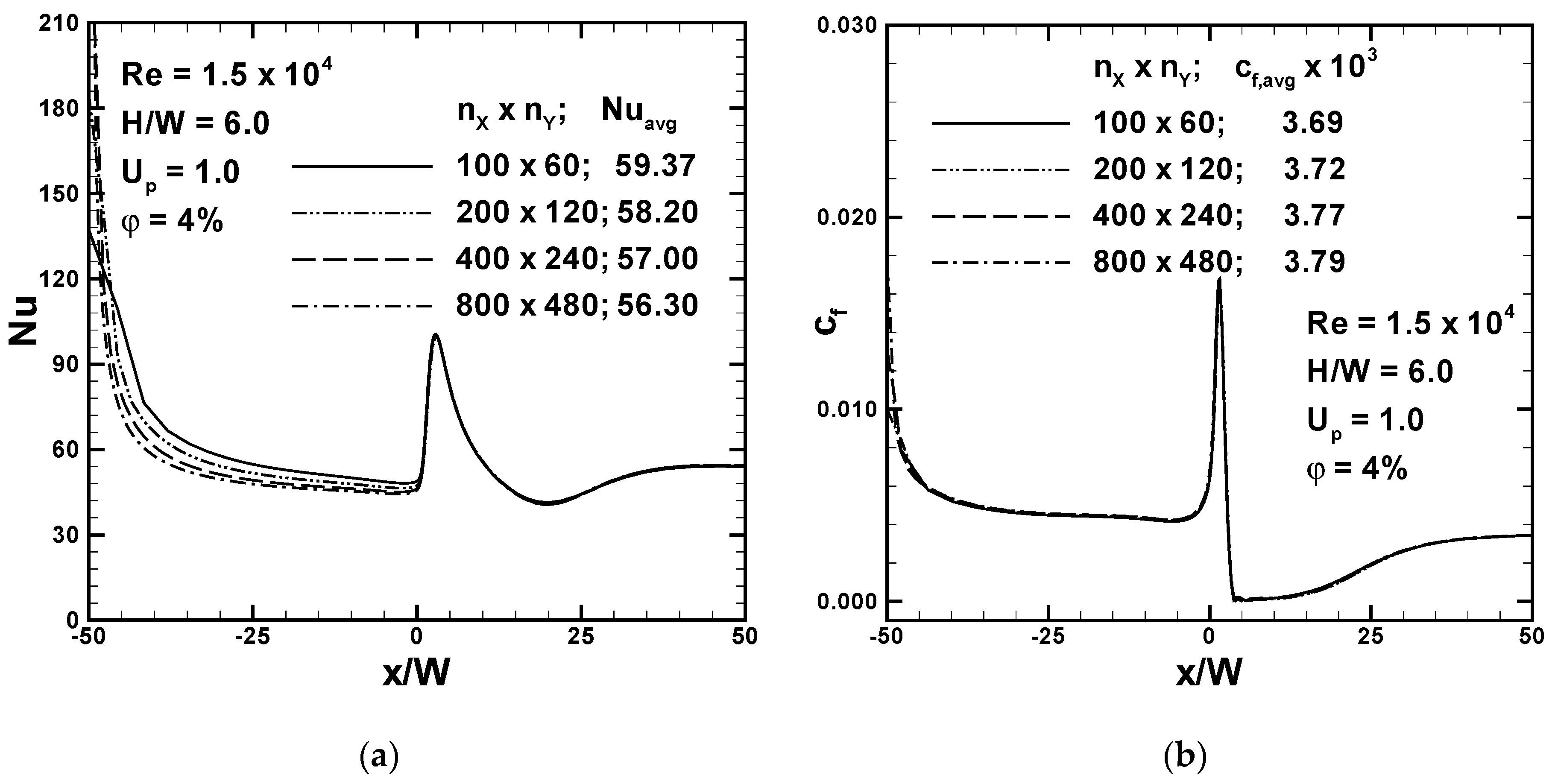
Grid sensitivity tests were conducted to obtain a more convenient grid size by monitoring the Nusselt number and the skin friction along the moving plate. Four different non-uniform meshes were tested on the model with H/W = 6 at Re = 15000, considering a nanofluid in which the volumetric fraction of the nanoparticles was 4%, and the dimensionless velocity of the moving plate was equal to 1. They had nx × ny nodes equal to 100 × 60, 200 × 120, 400 × 240, and 800 × 480. Meshes had finer distributions of nodes near walls and the jet inlet, which became sparser toward the exit sections, as shown in Figure 1b. For all the cases considered, the dimensionless distance y+ of the first node near the wall was less than 3. The local Nusselt number, Nu, and the skin friction, Cf, along the moving plate are shown in Figure 2 for the four different meshes considered. Moreover, in the same figure, the values of the average Nusselt number and of the skin friction coefficient are also reported. It is observed, in Figure 2a, that the significant differences of the Nusselt number between the finest mesh and the coarsest mesh were detected near the exit section on the left and they were significantly reduced close to the impinging jet. This discrepancy decreased upon increasing the nodes of the mesh. Furthermore, in Figure 2b, it is noted that the differences between skin friction coefficient profiles were insignificant for different meshes. The third grid was adopted because the comparison with the fourth one, in terms of average Nusselt number and average skin friction, showed relative errors equal to 1.2% and 0.5%.
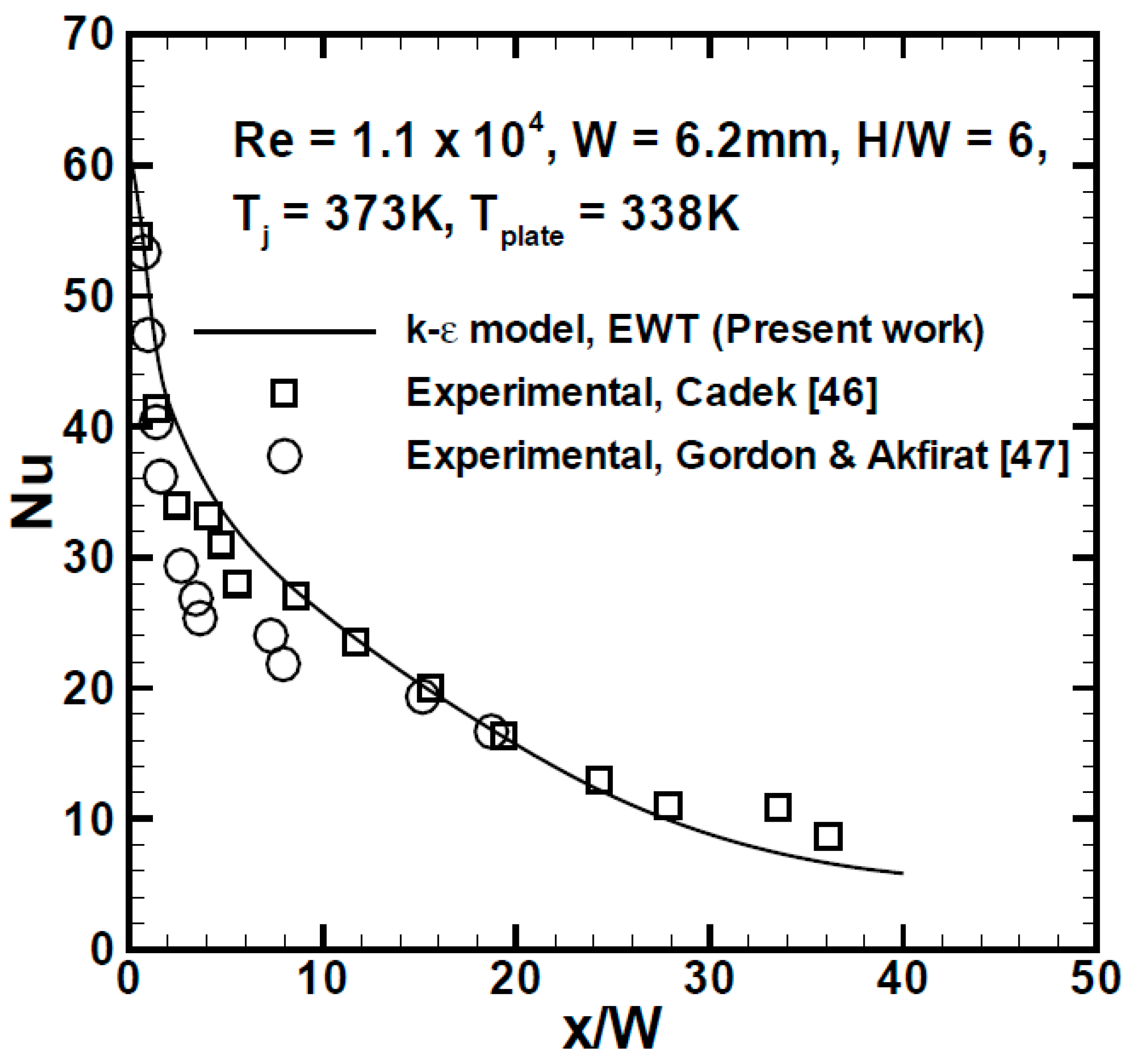
The numerical simulation was validated by comparing the obtained numerical data with the experimental and numerical data given in References [21,46,47]. In these papers, the working fluid was air. Figure 3 presents the comparison in terms of the local Nusselt number profiles along the target wall for the case characterized by Re = 11000, H/W = 6, Tj = 373 K, and Tplate = 338 K, and the obtained results are in good agreement with the experimental ones given in References [46,47] for stationary plates. In Table 4, the comparisons with the results given in Reference [21] in the case of a moving surface in terms of average values of the Nusselt number and the skin friction coefficient are reported. It is observed in Table 4 that the maximum discrepancies between the obtained results and the ones provided by Reference [21] are less than 5%.
5. Results and Discussion
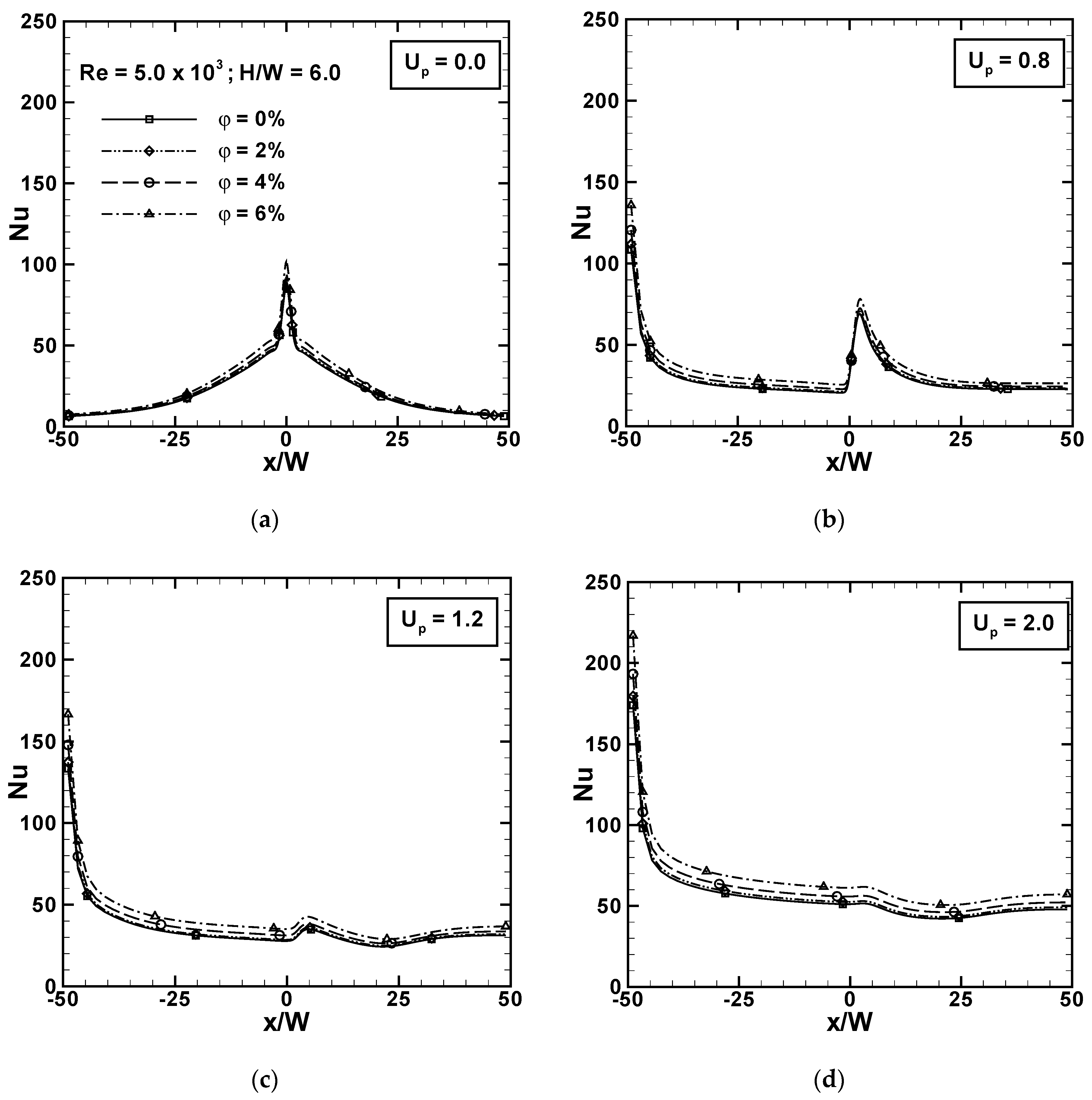
The Reynolds numbers considered in the simulations were from 5000 to 20000 and the volumetric concentration of Al2O3 nanoparticles in pure water varied between 0% to 6%. The main effect of the nanoparticles was a heat transfer increase for all values of surface-jet velocity ratio, as pointed out in Figure 4, for Re = 5000. The main effect caused by the moving plate was the significant reduction of the Nusselt number at the stagnation point, close to the jet impingement location, and the complete loss of symmetry in the local Nusselt number profiles along the heated plate, which agrees with the literature, see Reference [21]. The local Nusselt number at the stagnation point started from a maximum value for the stationary plate at a quasi-uniform value in the downstream region for the highest velocity plate, Up = 2.0. At an assigned x/W value, the effect of the volumetric concentration increase in the nanofluid mixture determined an increase in the local heat transfer for an assigned Reynolds number and Up, as shown in Figure 4. However, for Up = 0 in Figure 4a, a clear increment between −25 < x/W < 25 was observed with a maximum increase in the stagnation region. In Figure 4b–d, the maximum local Nusselt number was attained at the left open boundary, but this was a non-physical process, as underlined in Reference [21]. However, this problem was only local and had little influence on the global flow and thermal field [21]. For Up > 0, it is noted that the increase in the local Nusselt number due to the increase of the volumetric concentration increased as the surface-jet velocity ratio increased, as shown in Figure 4b–d. The increase was due to the increase in the thermal conductivity with increasing volumetric concentration and the velocity increase, which allowed the heated surface to move more rapidly toward the colder zone with a thinner boundary layer and a higher turbulent flow. The combined effect determined a lower thermal resistance, which facilitated the heat transfer.
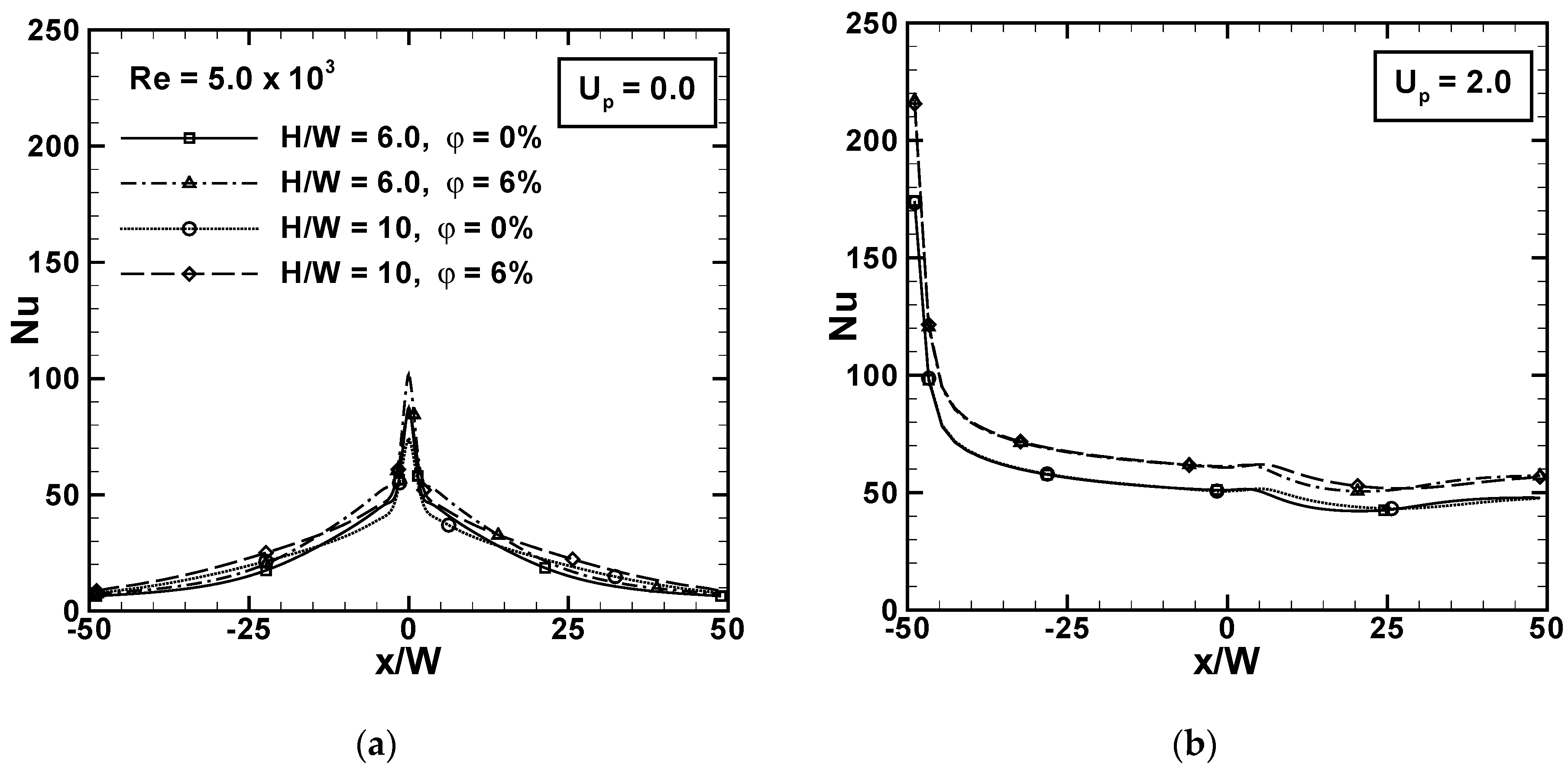
The heat transfer improvement did not depend significantly on the distance between the jet entrance section and moving surface, H/W, for the considered values equal to 6 and 10. For the lowest considered Reynolds value, equal to 5000, and in Figure 5, the differences between the two H/W values were small. However, the effect of the volumetric concentration was clearer, as shown in Figure 5b for Up = 2.0, where the increase in the local Nusselt number was about 16%, both in the stagnation region, around x/W = 0, and downstream of this zone. The increase was about the same for both the H/W values considered here. It is observed, in Figure 5b, that for this Re value, equal to 5000, the H/W variation did not affect the local Nusselt number upstream of the stagnation region up to about x/W = 5.0. This suggests that, in the surface heat transfer, upstream of x/W = 5, the diffusive effect prevailed. For Up = 0.0, in Figure 5a, the increase in the local Nusselt number, due to the volumetric concentration, was at a maximum at the stagnation point, in agreement with Reference [48].
For the highest considered Reynolds number equal to 20000, in Figure 6, at the same volumetric concentrations, 0% and 6%, the differences between the cases with H/W = 6 and H/W = 10 were greater than the previous considered Re. For Up = 2.0 in Figure 6b, the difference between the curves for H/W = 6 and H/W = 10 started upstream of the stagnation point, at about x/W = −10. These differences became clearer downstream of the stagnation point. In detail, the local heat transfer was higher for H/W = 10 than for H/W = 6 up to about x/W = 25, but downstream of this coordinate, the values of the two curves were switched. This could be due to the fact that the highest thermal gradient along the y-direction was changed along the x-direction. However, this did not depend on the presence of the nanoparticles but, in fact, is typical behavior of cases with a moving plate, as shown in References [21,37]. The nanofluid effect was related to an increase in the local Nusselt number of about 20% for the stationary and moving surfaces.
The increase in the local Nusselt number due to an increase in the volumetric concentration of the nanoparticles for different surface-jet velocity ratios is effectively summarized in Figure 7. The local Nu profiles along the heated surface are reported for Re = 5000 and 20000 in Figure 7a,b, respectively. It is interesting to observe, for the different Re but fixed Up, the trends were similar qualitatively, but the numerical values were completely different. In fact, the local Nu increased as the Re increases and the enhancement of the surface heat transfer, due to nanofluids, is higher as the Re value increased, as demonstrated in Figure 7b. The increase for Up = 0.8 was about 18%, whereas for Up = 2.0, it was about 22%, for Re = 5000, in Figure 7a. For Re = 20000, in Figure 7b, it was about 20% for Up = 0.8 and 2.0.
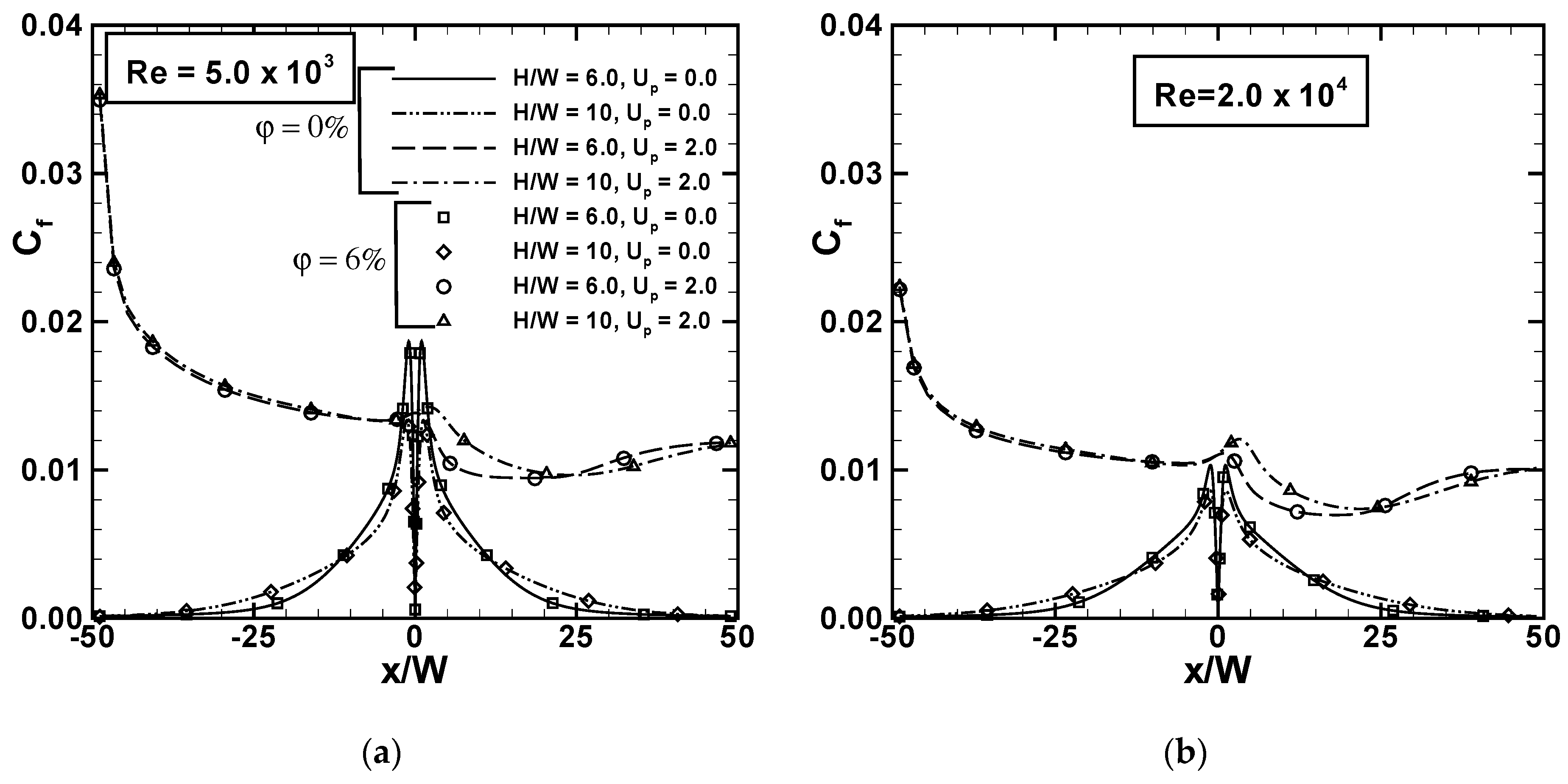
The presence of nanoparticles did not affect the dimensionless friction factor, Cf, defined in Equation (11) due to the assumption of constant properties. However, to highlight the effect of the moving surface on local Cf values, the profiles are reported in Figure 8 for Re = 5000 and 20000 and φ = 0 and 6%. The profiles are similar to the local Nu even if, at the stagnation point for Up = 0, it is equal to 0 and reached very high values in the stagnation region due to the high velocity gradient in the impingement region. The velocity gradient in the impingement region decreased, thereby increasing the surface-jet velocity ratio. These observations agree with Reference [21]. The stream function fields allowed for the fluid flow change related to the Up increase to be analyzed, as reported in Figure 9, for the lowest considered Re value, equal to 5000, and H/W = 6. For Up = 0 (the stationary surface) in Figure 9a, the classical pair of symmetrical counter-rotating vortices are on the sides of the jet. Upon increasing the Re, the vortices expanded due to the increase in the intensity of the flow motion. The increase of Up determined a distortion of the field due to the drag of the moving surface, as detected in Figure 9b,c. It is interesting to note that for Up = 0.8, in Figure 9b, there was a smaller vortex on the left side of the impinging jet, which determined two stagnation points. For the highest Up value, shown in Figure 9c, the secondary vortex disappeared and there was one stagnation point on the moving surface. The results agree with Reference [21].
Temperature fields, reported in Figure 10, followed the streamlines and the main differences between the pure water and the nanofluid are highlighted by solid lines, for φ = 0%, and dashed lines, for the mixture at 6.0%. It is noted that the nanofluids presented the highest temperature gradients close to the heated plate and higher Nusselt numbers. The effect was more pronounced as the Up and the Reynolds number increased, in agreement with the results given in Figure 4, Figure 5, Figure 6 and Figure 7.
The local Nusselt number increase determined a corresponding increase in the average Nusselt number Nuavg, defined in Equation (12) and as shown in Figure 11, as a function of the volumetric concentration. All curves, at assigned Up, showed a higher increase for higher volumetric concentration and this increase was greater for larger Up values. This was due to the presence of nanoparticles, which enhanced the thermal conductivity and viscosity of the mixture. The increase in the viscosity determined a greater drag of the moving plate, and consequently, a higher mass flow rate along the heated surface that augmented the heat transfer. This meant that there was a combined effect on the heat transfer. In fact, for Re = 5000 in Figure 11a, the increase of Nuavg with respect to the volumetric concentration passing from 0% to 6% was about 16% for Up = 0 and 20% for Up = 2.0, whereas the increase of Nuavg with respect to Up between 0 and 2.0 was 2.6 times greater for φ = 0% and 2.7 times greater for φ = 6%. For Re = 20000 in Figure 11b, the increase with respect to the volumetric concentration was about 17% for Up = 0 and about 19% for Up = 2.0. The increase with respect to Up for φ = 0% was about 2.5-fold and for φ = 6% is about 2.55-fold.
The effect of distance between the slot impinging jet section and the heated surface, referring to the slot width, H/W, was weak and practically negligible for Re = 5000, as shown in Figure 12. It seems that the more sensible changes were observed for the stationary surface. However, the results in Figure 12a,b, for φ = 0% and φ = 6%, respectively, allow Nuavg values to be compared directly and highlight the increase due to the presence of the nanoparticles, as underlined in the discussion regarding Figure 11.
The average friction factor, Cf,avg, as a function of the Reynolds number is reported in Figure 13 for Up = 0 and 2.0 and H/W = 6 and 10. It is noted that the greater the Up value, the greater the range of variation, and for an assigned Re value, the Cf,avg values for Up = 0.4 were lower than those of the Cf,avg values for Up = 0. This was more evident for H/W = 10 in Figure 13b, in agreement with Reference [21].
The average Nusselt number, Nuavg, values evaluated using the results of the simulations were correlated in terms of the Reynolds numbers and surface-jet velocity ratio. The correlation for φ = 0% was as follows:
with r2 = 0.99. The correlation was for 5000 ≤ Re ≤ 20000 and 0 ≤ Up ≤ 2.0.
The ratio between the average Nusselt number for nanofluids, Nuavg, and the one for the base fluid, Nu0,avg, was correlated to the volumetric concentration φ, as:
with r2 = 0.98 and for 0 ≤ φ ≤ 6%.
6. Conclusions
A numerical analysis of a two-dimensional turbulent mode for a confined slot jet impinging on a moving isothermal surface and operating with nanofluids was carried out. Different volume concentrations of Al2O3 nanoparticles were taken into account, assuming a single-phase model approach. Results showed that the effect of the increase in the velocity of the moving plate was the significant reduction of local Nusselt numbers at the stagnation point and their quasi-uniform values along the moving plate downstream of the stagnation point, according to the literature [21]. The combined effect of the moving plate and nanofluids resulted in a greater increase of the local Nusselt number in the downstream region. The maximum increase of the local Nusselt number was about 20% for the heated surface, both in stationary and moving conditions. A weak dependence on H/W for the considered values equal to 6 and 10 was detected. As expected, the volumetric concentration of the mixture did not affect the stream function and friction factor, and the trends of the local friction factor were very similar to the local Nusselt number trends, as found in Reference [21]. The average Nusselt number presented larger increases for the higher surface-jet velocity ratio, with increases of up to 20% for assigned Up and an over 2.5-fold increase in the Nu value for water in the stationary plate condition.
Moreover, two correlations were proposed, one among the average Nusselt number for pure water, φ = 0%, the Reynolds number, Re, and the surface-jet velocity ratio, Up; and the other for the ratio between the average Nusselt number for nanofluids, Nuavg, and the average Nusselt number for the base fluid, Nu0,avg, and the volumetric concentration, φ. They were defined in the ranges: 5000 ≤ Re ≤ 20000, 0 ≤ Up ≤ 2.0, and 0 ≤ φ ≤ 0.06, for 6 ≤ H/W ≤ 10.
It should be underlined that the assumption of temperature-independent properties can result in certain limitations in the results. This is mainly related to the viscosity dependence on temperature, which can affect the results within an error of 20% [49]. A correction for the evaluation of the average Nusselt number is to multiply the value obtained using Equation (19) by (μj/μp)1/4, as given in Reference [50]. Another limitation is related to the non-Newtonian behavior of nanofluids, as recently investigated in Reference [51] for a laminar regime. This point should be analyzed in the turbulent regime to evaluate the possible differences with respect to the Newtonian approach.
Author Contributions
Conceptualization, B.B., O.M., N.S.B. and M.A.S.; methodology, B.B. and M.A.S.; software, B.B.; validation, B.B. and O.M.; formal analysis, B.B., O.M., N.S.B. and M.A.S.; investigation, B.B. and O.M.; resources, O.M. and Mikhail Sheremet; data curation, B.B. and N.S.B.; writing—original draft preparation, B.B., O.M., N.S.B. and M.A.S.; writing—review and editing, B.B., O.M., N.S.B. and M.A.S.; visualization, B.B. and N.S.B.; supervision, N.S.B.; project administration, O.M.; funding acquisition, O.M..
Funding
This research was funded by MIUR (Ministero dell’Istruzione, dell’Università e della Ricerca), grant number PRIN-2017F7KZWS.
Conflicts of Interest
The authors declare no conflict of interest.
Nomenclature
| Symbol | Quantity | SI Unit/Equation |
| a | thermal diffusivity | m2∙s−1 |
| Cf | skin friction coefficient | Equation (11) |
| cp | specific heat | J∙kg−1∙K−1 |
| H | channel height | m |
| k | turbulent kinetic energy | m2∙s−2 |
| L | channel length in computational domain | m |
| Nu | Nusselt number | Equation (11) |
| Nu0 | Nusselt number for base fluid | |
| P | pressure | Pa |
| Pr = υ/a | Prandtl number | |
| Re | Reynolds number | Equation (11) |
| T | temperature | K |
| u | velocity component | m∙s−1 |
| Up | dimensionless plate velocity/surface-jet velocity ratio | Equation (11) |
| Vj | jet velocity | m∙s−1 |
| W | nozzle width | m |
| x, y | Cartesian coordinates | m |
| dimensionless wall distance | ||
| Greek symbols | ||
| ε | turbulence dissipation rate | m2∙s−3 |
| λ | thermal conductivity | W∙m−1∙K−1 |
| μ | dynamic viscosity | Pa s |
| υ | Kinematic viscosity | m2∙s−1 |
| ρ | density | kg∙m-3 |
| τw | wall shear stress | N∙m−2 |
| φ | nanoparticle volumetric concentration | |
| Subscripts | ||
| bf | base fluid | |
| f | fluid | |
| j | jet | |
| avg | average | |
| nf | nanofluid | |
| np | nanoparticle | |
| p | plate | |
| t | turbulent quantity | |
| 0 | reference value | |
References
- Webb, R.L.; Kim, N.H. Principles of Enhanced Heat Transfer, 2nd ed.; Taylor & Francis Group: New York, NY, USA, 2005. [Google Scholar]
- Martin, H. Heat and Mass Transfer between Impinging Gas Jets and Solid Surface. Adv. Heat Transf. 1977, 13, 1–60. [Google Scholar]
- Jambunathan, K.; Lai, E.; Moss, M.; Button, B. A review of heat transfer data for single circular jet impingement. Int. J. Heat Fluid Flow 1992, 13, 106–115. [Google Scholar] [CrossRef]
- Viskanta, R. Heat transfer to impinging isothermal gas and flame jets. Exp. Therm. Fluid Sci. 1993, 6, 111–134. [Google Scholar] [CrossRef]
- Ebadian, M.A.; Lin, C.X. A review of high-heat-flux heat removal technologies. ASME J. Heat Transf. 2011, 133, 110801. [Google Scholar] [CrossRef]
- Shukla, A.K.; Dewan, A. Flow and thermal characteristics of jet impingement: Comprehensive review. Int. J. Heat Technol. 2017, 35, 153–166. [Google Scholar] [CrossRef]
- Chauhan, R.; Singh, T.; Thakur, N.S.; Kumar, N.; Kumar, R.; Kumar, A. Heat transfer augmentation in solar thermal collectors using impinging air jets: A comprehensive review. Renew. Sustain. Energy Rev. 2018, 82, 3179–3190. [Google Scholar] [CrossRef]
- Subba Raju, K.; Schlünder, E.U. Heat transfer between an impinging jet and a continuously moving flat surface. Warme-stoffubertrag. 1977, 10, 131–136. [Google Scholar] [CrossRef]
- Huang, P.G.; Mujumdar, A.S.; Douglas, W.J.M. Numerical prediction of fluid flow and heat transfer under a turbulent impinging slot jet with surface motion and crossflow. ASME Pap. 1984, 84-WA/HT-33, 1–8. [Google Scholar]
- Zumbrunnen, D.A. Convective heat and mass transfer in the stagnation region of a laminar planar jet impinging on a moving surface. ASME J. Heat Transf. 1991, 113, 563–570. [Google Scholar] [CrossRef]
- Zumbrunnen, D.A.; Incropera, F.P.; Viskanta, R. A laminar boundary layer model of heat transfer due to a nonuniform planar jet impinging on a moving plate. Warme-Stoffubertrag. 1992, 27, 311–319. [Google Scholar] [CrossRef]
- Chen, J.; Wang, T.; Zumbrunnen, D.A. Numerical analysis of convective heat transfer from a moving plate cooled by an array of submerged planar jets. Numer. Heat Transf. A 1994, 26, 141–160. [Google Scholar] [CrossRef]
- Dinu, C.A.; Beasley, D.E.; Liburdy, J.A. Heat transfer from a moving plate to a confined impinging jet. ASME Publ. HTD 1998, 357, 195–202. [Google Scholar]
- Yang, Y.-T.; Hao, T.-P. Numerical studies of three turbulent slot jets with and without moving surface. Acta Mech. 1999, 136, 17–27. [Google Scholar] [CrossRef]
- Chattopadhyay, H.; Biswas, G.; Mitra, N.K. Heat transfer from a moving surface due to impinging slot jets. ASME J. Heat Transf. 2002, 124, 433–440. [Google Scholar] [CrossRef]
- Chattopadhyay, H.; Saha, S.K. Simulation of laminar slot jets impinging on a moving surface. ASME J. Heat Transf. 2002, 124, 1049–1055. [Google Scholar] [CrossRef]
- Chattopadhyay, H.; Saha, S.K. Turbulent flow and heat transfer from a slot jet impinging on a moving plate. Int. J. Heat Fluid Flow 2003, 24, 685–697. [Google Scholar] [CrossRef]
- Chattopadhyay, H. Effect of surface motion on transport processes due to circular impinging jets—A numerical study. Dry. Technol. 2006, 24, 1347–1351. [Google Scholar] [CrossRef]
- Senter, J.; Solliec, C. Flow field analysis of a turbulent slot air jet impinging on a moving flat surface. Int. J. Heat Fluid Flow 2007, 28, 708–719. [Google Scholar] [CrossRef]
- Aldabbagh, L.B.Y.; Mohamad, A.A. A three-dimensional numerical simulation of impinging jet arrays on a moving plate. Int. J. Heat Mass Transf. 2009, 52, 4894–4900. [Google Scholar] [CrossRef]
- Sharif, M.A.R.; Banerjee, A. Numerical analysis of heat transfer due to confined slot-jet impingement on a moving plate. Appl. Therm. Eng. 2009, 29, 532–540. [Google Scholar] [CrossRef]
- Chattopadhyay, H.; Cemal Benim, A. Turbulent heat transfer over a moving surface due to impinging slot jets. ASME J. Heat Transf. 2011, 133, art-104502. [Google Scholar] [CrossRef]
- Badra, J.; Masri, A.R.; Behnia, M. Enhanced transient heat transfer from arrays of jets impinging on a moving plate. Heat Transf. Eng. 2013, 34, 361–371. [Google Scholar] [CrossRef]
- Benmouhoub, D.; Mataoui, A. Turbulent heat transfer from a slot jet impinging on a flat plate. ASME J. Heat Transf. 2013, 135, 102201. [Google Scholar] [CrossRef]
- Başaran, A.; Selimefendigil, F. Numerical study of heat transfer due to twinjets impingement onto an isothermal moving plate. Math. Comput. Appl. 2013, 18, 340–350. [Google Scholar] [CrossRef]
- Ersayin, E.; Selimefendigil, F. Numerical investigation of impinging jets with nanofluids on a moving plate. Math. Comput. Appl. 2013, 18, 428–437. [Google Scholar] [CrossRef]
- Kadiyala, P.K.; Chattopadhyay, H. Neuro-genetic optimization of laminar slot jets impinging on a moving surface. Int. Commun. Heat Mass Transf. 2014, 59, 143–147. [Google Scholar] [CrossRef]
- Bai, G.-P.; Gong, G.-C.; Zhao, F.-Y.; Lin, Z.-X. Multiple thermal and moisture removals from the moving plate opposite to the impinging slot jet. Appl. Therm. Eng. 2014, 66, 252–265. [Google Scholar] [CrossRef]
- Benmouhoub, D.; Mataoui, A. Computation of heat transfer of a plane turbulent jet impinging a moving plate. Therm. Sci. 2014, 18, 1259–1271. [Google Scholar] [CrossRef]
- Aghahani, M.; Eslami, G.; Hadidi, A. Heat transfer in a turbulent jet impinging on a moving plate considering high plate-to-jet velocity ratios. J. Mech. Sci. Technol. 2014, 28, 4509–4516. [Google Scholar] [CrossRef]
- Benmouhoub, D.; Mataoui, A. Inclination of an impinging jet on a moving wall to control the stagnation point location. Int. J. Therm. Sci. 2015, 89, 294–304. [Google Scholar] [CrossRef]
- Benmouhoub, D.; Mataoui, A. Heat transfer control of an impinging inclined slot jets on a moving wall. Heat Transf.—Asian Res. 2015, 44, 568–584. [Google Scholar] [CrossRef]
- Rahimi, M.; Soran, R.A. Slot jet impingement heat transfer for the cases of moving plate and moving nozzle. J. Braz. Soc. Mech. Sci. Eng. 2016, 38, 2651–2659. [Google Scholar] [CrossRef]
- Achari, A.M.; Das, M.K. Conjugate heat transfer study of a turbulent slot jet impinging on a moving plate. Heat Mass Transf. 2017, 53, 1017–1035. [Google Scholar] [CrossRef]
- Kadiyala, P.K.; Chattopadhyay, H. Numerical simulation of transport phenomena due to array of round jets impinging on hot moving surface. Dry. Technol. 2017, 35, 1742–1754. [Google Scholar] [CrossRef]
- Shashikant; Patel, D.K. Numerical study of conjugate heat transfer due to impingement of turbulent slot jet onto a moving flat plate. In Proceedings of the 5th International Conference on Computational Methods for Thermal Problems, Bengaluru, India, 1–9 July 2018; Massarotti, N., Nithiarasu, P., Dutta, P., Ranganayakulu, C., Eds.; Dalian University of Technology: Dalian, China, 2018; pp. 771–776. [Google Scholar]
- Kadiyala, P.K.; Chattopadhyay, H. Numerical analysis of heat transfer from a moving surface due to impingement of slot jets. Heat Transf. Eng. 2018, 39, 98–106. [Google Scholar] [CrossRef]
- Launder, B.E.; Spalding, D.B. The numerical computation of turbulent flows. Comp. Meth. Appl. Mech. Eng. 1974, 3, 269–289. [Google Scholar] [CrossRef]
- Sun, Q.; Pop, I. Free convection in a triangle cavity filled with a porous medium saturated with nanofluids with flush mounted heater on the wall. Int. J. Therm. Sci. 2011, 50, 2141–2153. [Google Scholar] [CrossRef]
- Chon, C.H.; Kihm, K.D.; Lee, S.P.; Choi, S.U.S. Empirical Correlation Finding the Role of Temperature and Particle Size for Nanofluid (Al2O3) Thermal Conductivity Enhancement. Appl. Phys. Lett. 2005, 87, 1–3. [Google Scholar] [CrossRef]
- Khanafer, K.; Vafai, K.; Lightstone, M. Buoyancy-driven heat transfer enhancement in a two-dimensional enclosure utilizing nanofluids. Int. J. Heat Mass Transf. 2003, 46, 3639–3653. [Google Scholar] [CrossRef]
- Vajjha, R.S.; Das, D.K.; Namburu, P.K. Numerical study of fluid dynamic and heat transfer performance of Al2O3 and CuO nanofluids in the flat tubes of a radiator. Int. J. Heat Fluid Flow 2010, 31, 613–621. [Google Scholar] [CrossRef]
- Vajjha, R.S.; Das, D.K. Experimental determination of thermal conductivity of three nanofluids and development of new correlations. Int. J. Heat Mass Transf. 2009, 52, 4675–4682. [Google Scholar] [CrossRef]
- FLUENT Computational Fluid Dynamic Code Version 19.2 User Guide, Fluent, Inc. Available online: www.ansys.com (accessed on 10 January 2019).
- Wolfstein, M. The velocity and temperature distribution of one-dimensional flow with turbulence augmentation and pressure gradient. Int. J. Heat Mass Transf. 1969, 12, 301–318. [Google Scholar] [CrossRef]
- Cadek, F.F.A. Fundamental Investigation of Jet Impingement Heat Transfer. Ph.D. Thesis, University of Cincinnati, Cincinnati, OH, USA, 1968. [Google Scholar]
- Gordon, R.; Akfirat, J.C. Heat transfer characteristics of impinging two-dimensional air jets. ASME J. Heat Transf. 1966, 88, 101–108. [Google Scholar] [CrossRef]
- Manca, O.; Mesolella, P.; Nardini, S.; Ricci, D. Numerical study of a confined slot impinging jet with nanofluids. Nanoscale Res. Lett. 2011, 6, 188. [Google Scholar] [CrossRef]
- Nguyen, C.T.; Desgranges, F.; Galanis, N.; Roy, G.; Maré, T.; Boucher, S.; Angue Mintsa, H. Viscosity data for Al2O3–water nanofluid—Hysteresis: Is heat transfer enhancement using nanofluids reliable? Int. J. Therm. Sci. 2008, 47, 103–111. [Google Scholar] [CrossRef]
- Whitaker, S. Elementary Heat Transf. Analysis; Pergamon Press: New York, NY, USA, 1976. [Google Scholar]
- Lamraoui, H.; Mansouri, K.; Saci, R. Numerical investigation on fluid dynamic and thermal behavior of a non-Newtonian Al2O3–water nanofluid flow in a confined impinging slot jet. J. Non-Newton. Fluid Mech. 2019, 265, 11–27. [Google Scholar] [CrossRef]
Figure 1.
(a) Impinging jet with boundary conditions, and (b) computational domain and mesh.

Figure 2.
Grid dependence analysis: (a) Nusselt number and (b) skin friction coefficient.

Figure 3.
Validation of the numerical results, in terms of local Nusselt number, with experimental data from References [46,47].

Figure 4.
Local Nusselt number profiles along the moving surface, for Re = 5.0 × 10³, H/W = 6.0, φ = 0% and 6%, and: (a) Up = 0.0, (b) Up = 0.8, (c) Up = 1.2, and (d) Up = 2.0.
Figure 4.
Local Nusselt number profiles along the moving surface, for Re = 5.0 × 10³, H/W = 6.0, φ = 0% and 6%, and: (a) Up = 0.0, (b) Up = 0.8, (c) Up = 1.2, and (d) Up = 2.0.

Figure 5.
Local Nusselt number profiles along the moving surface, for Re = 5.0 × 10³, H/W = 6.0 and 10, φ = 0% and 6%, and: (a) Up = 0.0 and (b) Up = 2.0.
Figure 5.
Local Nusselt number profiles along the moving surface, for Re = 5.0 × 10³, H/W = 6.0 and 10, φ = 0% and 6%, and: (a) Up = 0.0 and (b) Up = 2.0.

Figure 6.
Local Nusselt number profiles along the moving surface, for Re = 2.0 × 10⁴, H/W = 6.0 and 10, φ = 0% and 6%, and: (a) Up = 0.0 and (b) Up = 2.0.
Figure 6.
Local Nusselt number profiles along the moving surface, for Re = 2.0 × 10⁴, H/W = 6.0 and 10, φ = 0% and 6%, and: (a) Up = 0.0 and (b) Up = 2.0.

Figure 7.
Local Nusselt number profiles for H/W = 6.0; Up = 0, 0.8, and 2.0; φ = 0 and 6%; and: (a) Re = 5000 and (b) Re = 20000.
Figure 7.
Local Nusselt number profiles for H/W = 6.0; Up = 0, 0.8, and 2.0; φ = 0 and 6%; and: (a) Re = 5000 and (b) Re = 20000.

Figure 8.
Local friction factor profiles along the heated surface for H/W = 6.0 and 10, Up = 0.0 and 2.0, and φ = 0% and 6% for (a) Re = 5000 and (b) Re = 20000.
Figure 8.
Local friction factor profiles along the heated surface for H/W = 6.0 and 10, Up = 0.0 and 2.0, and φ = 0% and 6% for (a) Re = 5000 and (b) Re = 20000.

Figure 9.
Stream function for Re = 5000, H/W = 6, and (a) Up = 0, (b) Up = 0.8, and (c) Up = 1.6.

Figure 10.
Dimensionless temperature fields for H/W = 6: (a–c) Re = 5000 and (d–f) for Re = 20000 (φ = 0—solid lines and φ = 6%—dashed lines).
Figure 10.
Dimensionless temperature fields for H/W = 6: (a–c) Re = 5000 and (d–f) for Re = 20000 (φ = 0—solid lines and φ = 6%—dashed lines).

Figure 11.
Average Nusselt number as a function of the volumetric concentration for H/W = 6.0, different Up values, and (a) Re = 5000 and (b) Re = 20000.
Figure 11.
Average Nusselt number as a function of the volumetric concentration for H/W = 6.0, different Up values, and (a) Re = 5000 and (b) Re = 20000.

Figure 12.
Average Nusselt number as a function of the Reynolds number for H/W = 6 and 10, and (a) φ = 0 and (b) φ = 0.06.
Figure 12.
Average Nusselt number as a function of the Reynolds number for H/W = 6 and 10, and (a) φ = 0 and (b) φ = 0.06.

Figure 13.
Friction factor/skin friction coefficient as a function of Reynolds number for different Up and (a) H/W = 6 and (b) H/W = 10.
Figure 13.
Friction factor/skin friction coefficient as a function of Reynolds number for different Up and (a) H/W = 6 and (b) H/W = 10.

Figure 14.
(a) Correlation for the average Nusselt number ratio and (b) deviation between estimated value by correlation and numerical data.
Figure 14.
(a) Correlation for the average Nusselt number ratio and (b) deviation between estimated value by correlation and numerical data.


Table 1.
Summary of open literature for slot jet on moving plate.
| References (Year) | Experimental (Exp)/Numerical (Num) | Constant/Variable Properties (CP/VP) | Surface-to-Jet Velocity Ratio | Fluid | Turbulent Model or Laminar | Reynolds Number Range |
|---|---|---|---|---|---|---|
| [8] (1977) | Exp | - | 0.0375–1.375 | air | - | 70,000–59,0000 |
| [9] (1984) | Num | CP | - | air | Turbulent (k-ε) | - |
| [10] (1991) | Num | CP | - | air | Laminar | - |
| [11] (1992) | Num | CP | - | gas/water | Laminar | - |
| [13] (1998) | Num | CP | 0–1 | - | Laminar | 500–2000 |
| [14] (1999) | Num | CP | 4–20 | air | Turbulent (k-ε) | 11,000–44,000 |
| [15] (2002) | Num | CP | 0.1–2.0 | air | Turbulent (LES) | 500–3000 |
| [16] (2002) | Num | CP | 0–2.0 | air | Laminar | 100, 200 |
| [17] (2003) | Num | CP | 0.1–1.0 | air | Turbulent (LES) | 5800 |
| [19] (2007) | Exp | - | 0–1.0 | air | - | 5300, 8000, 10,600 |
| [21] (2009) | Num | CP | 0–2.0 | air | Turbulent (k-ε) | 5000–20,000 |
| [22] (2011) | Num | CP | 0–2.0 | air | Turbulent (k-ε) | 3000–50,000 |
| [23] (2013) | Num | CP | 0, 0.00022 | air | Turbulent (k-ω and V2F) | 5000–66,000 |
| [24] (2013) | Num | CP | 0–4.0 | air | Turbulent (k-ε) | 10,000–25,000 |
| [25] (2013) | Num | CP | 0–2.0 | nanofluid water/Al2O3 | Laminar | 50–200 |
| [26] (2013) | Num | CP | 0–2.0 | nanofluid water/Al2O3 | Laminar | 100–400 |
| [27] (2014) | Num | CP | 0–2.0 | air | Laminar | 100, 200 |
| [28] (2014) | Num | CP | 0–5.0 | air, moisture | Laminar and buoyancy effect | 200 |
| [29] (2014) | Num | CP | 0–4.0 | air | Turbulent (k-ω) | 10,000–25,000 |
| [30] (2014) | Num | CP | 0–6.0 | air | Turbulent (V2-f) | 3000–60,000 |
| [31] (2015) | Num | CP | 0–1.75 | air | Turbulent (RSM) | 10,000–25,000 |
| [32] (2015) | Num | CP | 0–1.75 | air | Turbulent (RSM) | 10,000–25,000 |
| [33] (2016) | Num | CP | 0–0.5 | air | Laminar | 500 |
| [34] (2017) | Num | CP | 0–1.0 | air | Turbulent (k-ε) | 15,000 |
| [36] (2018) | Num | CP | 0–0.25 | air | Turbulent (k-ε) | 9900 |
| [37] (2018) | Num | CP | 0–6.0 | air | Laminar Turbulent (SST) | 100–5000 |
Table 2.
Thermophysical properties at a temperature of 293 K.
| Material | ρ [kg/m3] | cp [J/kg K] | μ [Pa s] | λ [W/mK] |
|---|---|---|---|---|
| Al2O3 | 3970 | 765 | - | 40 |
| Water | 997 | 4179 | 890 × 10−6 | 0.613 |
Table 3.
Nanofluid properties adopted in the present paper.
| φ | ρ [kg/m3] | cnp [J/kgK] | μ [Pa∙s] | λ [W/mK] |
|---|---|---|---|---|
| 0% | 997 | 4179 | 890 × 10−6 | 0.613 |
| 1% | 1027 | 4047 | 996 × 10−6 | 0.660 |
| 2% | 1057 | 3922 | 1134 × 10−6 | 0.676 |
| 4% | 1116 | 3693 | 1469 × 10−6 | 0.711 |
| 6% | 1175 | 3487 | 1904 × 10−6 | 0.749 |
Table 4.
Comparisons with results given by Sharif and Banerjee [21], Re = 5000 and 20000, and H/W = 6 for the air in terms of the average Nusselt number and skin friction coefficient.
Table 4.
Comparisons with results given by Sharif and Banerjee [21], Re = 5000 and 20000, and H/W = 6 for the air in terms of the average Nusselt number and skin friction coefficient.
| Re = 5000 | ||||||
| Up | Nuavg | Nuavg [21] | Error (%) | Cf,avg | Cf,avg [21] | Error (%) |
| 0 | 8.50 | 8.40 | 1.2 | 0.0026 | 0.0025 | 4.0 |
| 2.0 | 16.97 | 16.50 | 2.8 | 0.0137 | 0.0135 | 1.4 |
| Re = 20,000 | ||||||
| Up | Nuavg | Nuavg [21] | Error (%) | Cf,avg | Cf,avg [21] | Error (%) |
| 0 | 27.12 | 26.80 | 1.2 | 0.0020 | 0.0019 | 5.0 |
| 2.0 | 51.00 | 49.00 | 4.0 | 0.0105 | 0.0103 | 1.9 |
© 2019 by the authors. Licensee MDPI, Basel, Switzerland. This article is an open access article distributed under the terms and conditions of the Creative Commons Attribution (CC BY) license (http://creativecommons.org/licenses/by/4.0/).
Share and Cite
MDPI and ACS Style
Buonomo, B.; Manca, O.; Bondareva, N.S.; Sheremet, M.A. Thermal and Fluid Dynamic Behaviors of Confined Slot Jets Impinging on an Isothermal Moving Surface with Nanofluids. Energies 2019, 12, 2074. https://doi.org/10.3390/en12112074
AMA Style
Buonomo B, Manca O, Bondareva NS, Sheremet MA. Thermal and Fluid Dynamic Behaviors of Confined Slot Jets Impinging on an Isothermal Moving Surface with Nanofluids. Energies. 2019; 12(11):2074. https://doi.org/10.3390/en12112074
Chicago/Turabian StyleBuonomo, Bernardo, Oronzio Manca, Nadezhda S. Bondareva, and Mikhail A. Sheremet. 2019. "Thermal and Fluid Dynamic Behaviors of Confined Slot Jets Impinging on an Isothermal Moving Surface with Nanofluids" Energies 12, no. 11: 2074. https://doi.org/10.3390/en12112074
Note that from the first issue of 2016, this journal uses article numbers instead of page numbers. See further details here.