Article

Reduction of Heat Losses in a Pre-Insulated Network Located in Central Poland by Lowering the Operating Temperature of the Water and the Use of Egg-shaped Thermal Insulation: A Case Study

by
Dorota Anna Krawczyk
* and
Tomasz Janusz Teleszewski
Department of HVAC Engineering, Bialystok University of Technology, 15-351 Bialystok, Poland
*
Author to whom correspondence should be addressed.
Energies 2019, 12(11), 2104; https://doi.org/10.3390/en12112104
Submission received: 4 May 2019 / Revised: 30 May 2019 / Accepted: 30 May 2019 / Published: 1 June 2019
(This article belongs to the Section B: Energy and Environment)

Abstract

:
This paper presents possible variants of reducing the heat loss in an existing heating network made from single pre-insulated pipes located in central Europe. In order to achieve this aim, simulations were carried out for five different variants related to the modification of the network operation temperature, replacement of a single network with a double pre-insulated one, and changes in the cross-section geometry of the thermal insulation of the double heating network from circular to egg-shaped. The proposed egg-shaped thermal insulation was obtained by modifying the shape of the Cassini oval, in that the supply pipe has a greater insulation thickness compared to the return pipe. The larger insulation field in the supply pipe contributed to reducing the heat flux density around the supply line and, as a result, to significantly reducing heat loss. The egg-shaped thermal insulation described in the publication in a mathematical formula can be used in practice. This work compares the heat losses for the presented variants and determines the ecological effect. Heat losses were determined using the boundary element method (BEM), using a proprietary computer program written as part of the VIPSKILLS 2016-1-PL01-KA203-026152 project Erasmus+.

1. Introduction

Pre-insulated heating networks are now widely used to transport heat from central energy sources to local consumers. Analyses of heat supply to customers by district heating networks indicate a significant reduction in pollution emitted to the atmosphere in cities. Guelpa at al. [1] showed that the construction of a network in urban areas causes a significant reduction of carbon dioxide emissions to the air, while Ravina et al. [2] pointed out that district heating networks could contribute to the reduction of emissions of nitrogen oxides and suspended particulates in the Italian city of Turin. The ecological effect may be raised by the cooperation of district heating networks pre-insulated especially by low-temperature heating networks with renewable heat sources [3,4]. The work of district heating networks is undoubtedly influenced by the management of district heating networks [5,6,7], as well as the type of local heat consumers [7,8]. The energy-saving operation of pre-insulated networks depends primarily on minimizing heat losses [9]. Reduction of heat losses contributes to the improvement of the ecological effect [10]. The presented results of research on double pre-insulated networks in Reference [11] showed that, in standard pre-insulated district heating networks with increasing pipe diameter and mass flow, heat losses increase. An increase in the operating temperature of the heating network also causes an increase in heat losses [12]. A reduction of heat losses can be obtained by changing the geometry of the position of the pipe in the thermal insulation or by changing the geometry of the cross-section of the thermal insulation. Reference [13] proposed a modification of the location of the heating ducts in a common circular insulation, resulting in a reduction of heat losses.
In district heating networks, pre-insulated double ducts with round thermal insulation are commonly used. This solution is characterized by the fact that, under the supply pipe, the insulation thickness is too small [14], resulting in a maximum heat flux at this point, while the left and right sides of the supply and return duct have a thermal insulation field with low heat transfer. The solution to this problem may be the use of an elliptical or oval-shaped thermal insulation, which would make it possible to obtain a more uniform thickness of thermal insulation around the heating ducts as compared to circular thermal insulation. The use of oval-shaped thermal insulation [15] or ellipses [10] results in the supply and return lines being insulated with the same thickness of thermal insulation. In pre-insulated heating networks, the temperature difference between the supply and return pipes can be significant, resulting in the supply pipe generating higher heat losses than the return pipe. In order to reduce heat losses through the supply pipe, it is possible to use such a modification of the shape of the thermal insulation that will allow the thickness of thermal insulation in the area of the supply pipe to be increased at the expense of the thermal insulation field in which the heat exchange is low. The solution to this problem may be the use of a shape of thermal insulation similar to the shape of an egg, which in the lower part is characterized by a greater thickness of thermal insulation, while in the upper part is characterized by a smaller thickness. Egg-shaped thermal insulations were published in Reference [16]. Unfortunately, the authors did not present mathematical formulas describing these shapes.
In this work, a mathematical formula of the contour of egg-shaped thermal insulation is presented and, based on an existing heating network in Poland, a comparison of egg-shaped thermal insulation with existing solutions is presented. Figure 1a presents a photograph of a prototype double pre-insulated pipe with egg-shaped thermal insulation, which was made as part of the VIPSKILLS 2016-1-PL01-KA203-026152 project Erasmus+, while Figure 1a shows the geometry and boundary conditions of the thermal insulation geometry presented in this work. The aim of the work was also to present the ecological effect of a district heating network with high-temperature and low-temperature options for the single pre-insulated network, double pre-insulated network with round thermal insulation, and double pre-insulated network with egg-shaped thermal insulation.

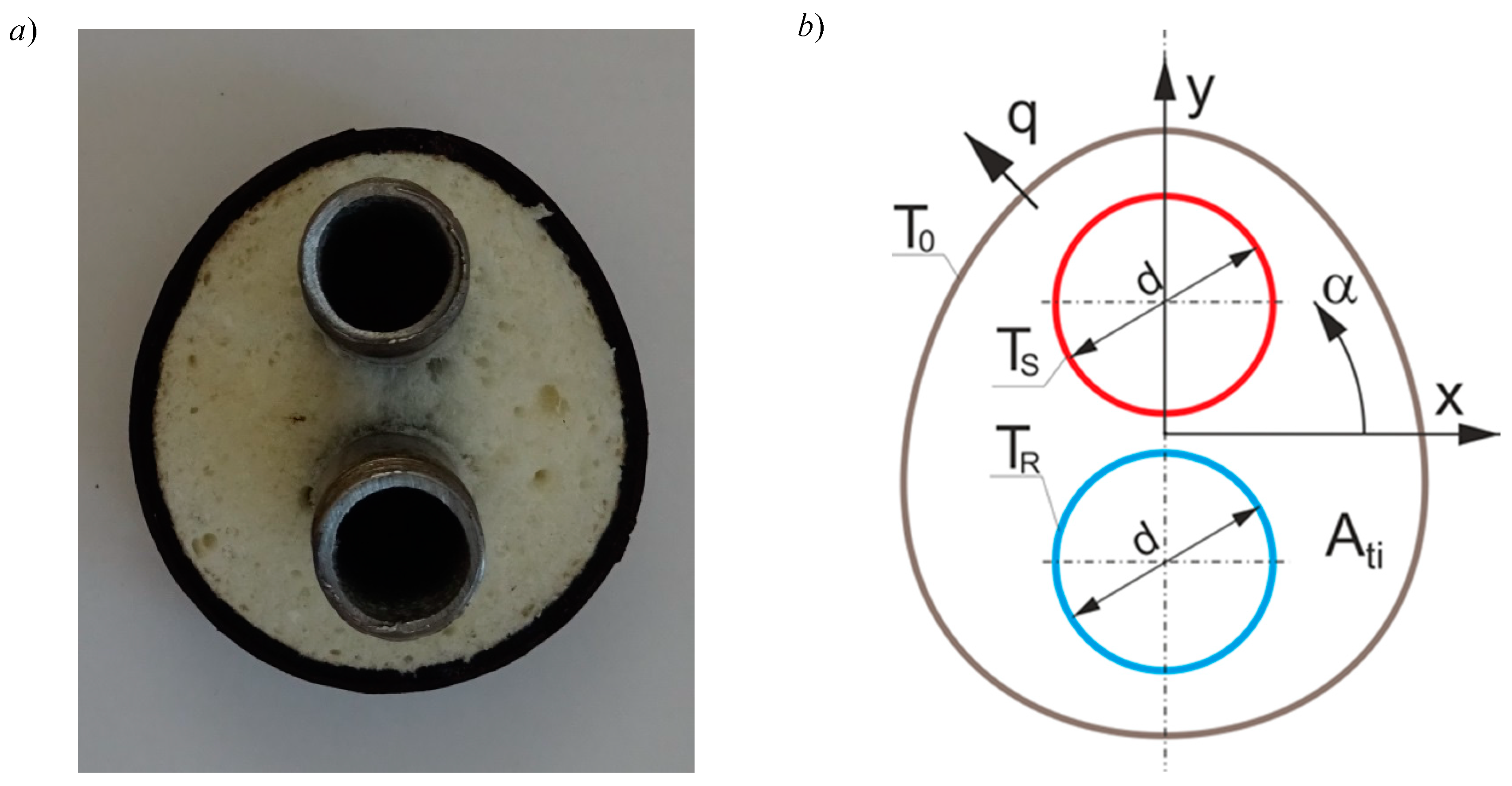
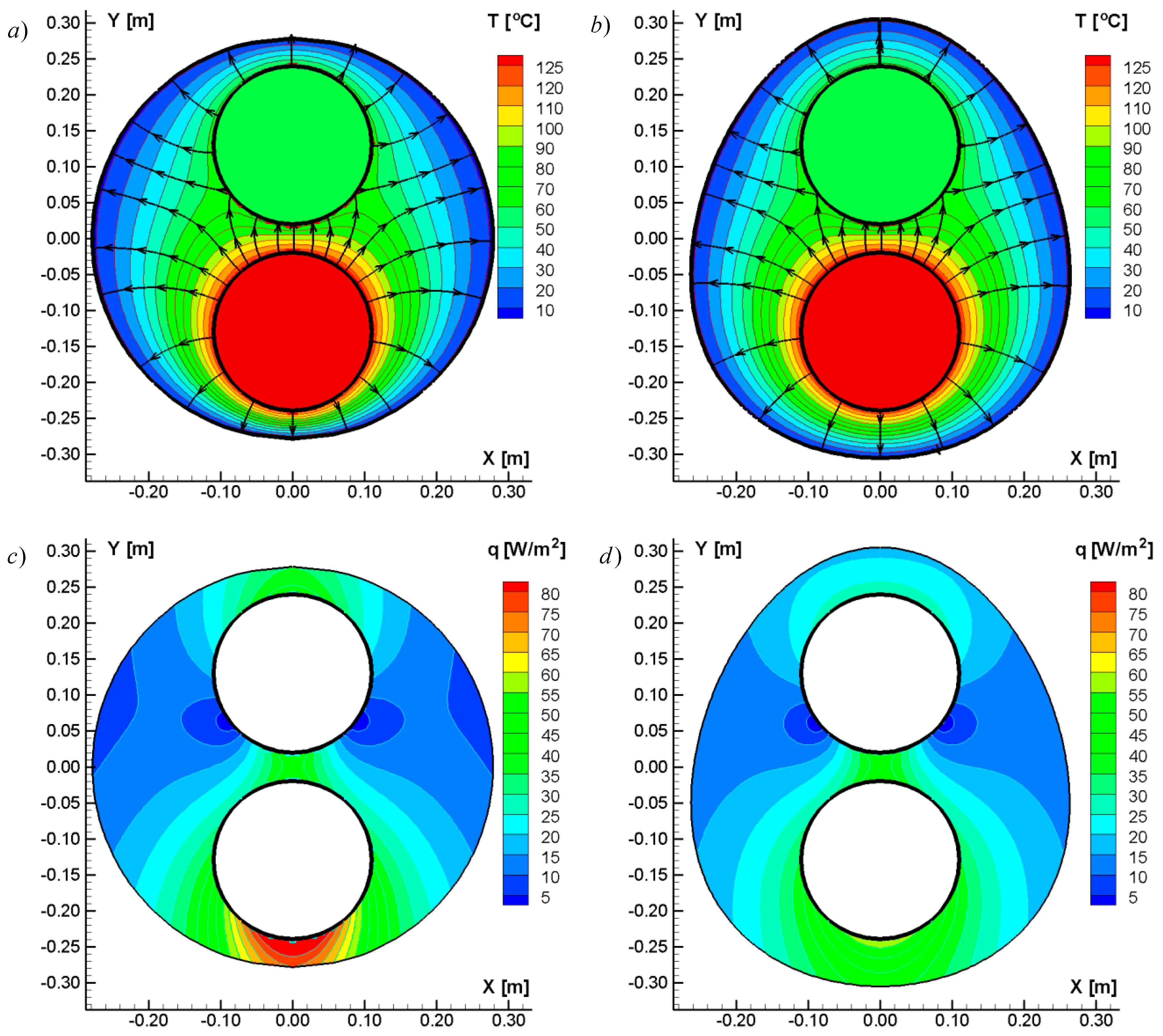
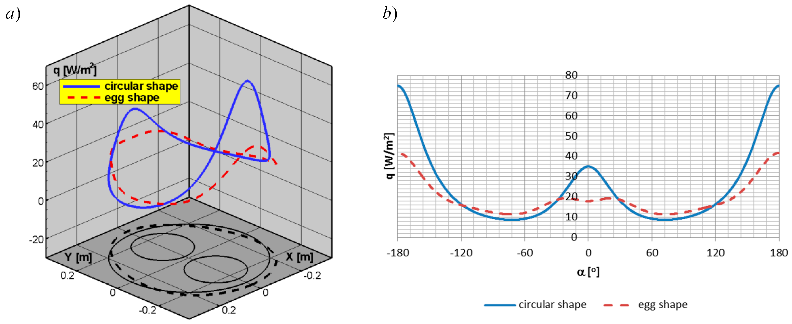
2. Optimization of the Shape of the Thermal Insulation for the Pre-Insulated Double Duct Based on the Temperature Field and the Heat Flux Density Distribution in the Cross-Section of the Thermal Insulation

Numerical studies of pre-insulated heating networks can be made on the basis of one-dimensional [17,18,19,20], two-dimensional [15,21], and three-dimensional [12,22] analytical or numerical models. For the purpose of this work, in order to perform numerical calculations, a calculation program of stationary two-dimensional heat conduction written in Fortran using the boundary element method was used, the verification of which was presented in References [10,14]. Details of the application of the boundary element method in thermal conductivity can be found in References [23,24]. The unit heat flux through the outer part of the thermal insulation can be determined from the Laplace equation as follows:
k ( 2 T x 2 + 2 T y 2 ) = 0
The boundary condition of Dirichlet is assumed for calculations as the temperature on the walls on the supply line TS and return line TR, which are equal to the temperature of the heating medium and the temperature on the outer surface of the thermal insulation, which is equal to ground temperature To = 8 °C. The thermal conductivity coefficient of thermal insulation (polyurethane foam) was assumed equal to k = 0.0265 W/(m·K). Detailed analysis of heat losses through the supply and return lines was presented in Reference [10]. The basic requirements for thermal insulation of pre-insulated heating networks are also described in the literature [25]. In order to optimize the shape of thermal insulation, the egg shape described in the following modified Cassini oval equation is proposed (Figure 1b):
x = S cos ( α ) a 2 cos ( 2 α ) + a 4 ( cos ( 2 α ) ) 2 a 4 + b 4 y = S sin ( α ) ( 1 + 0.03 x ) 2 a 2 cos ( 2 α ) + a 4 ( cos ( 2 α ) ) 2 a 4 + b 4 , a = 1 b = 2.5
where α is the coordinate of the cylindrical system, a and b are shape coefficients, and S is the scale factor depending on the thermal insulation field Ati.
After determining the temperature field in the cross-section of the thermal insulation of the pre-insulated double duct, the density of the heat flux within the area Ati can be determined from the following dependence (Figure 1b):
q = q x 2 + q y 2 , q x = k T x , q y = k T y
Optimization of the shape of thermal insulation can be based on the analysis of the heat flux density distribution in the cross-section of thermal insulation determined from Equation (3). For the following calculations (TS = 130 °C, TR = 55 °C), a cross-section of a pre-insulated double heating network with round thermal insulation with an external diameter D = 560 mm was assumed, in which the diameters of the supply and return ducts were equal to d = 291.1 mm with egg-shaped thermal insulation, whose cross-sectional area is the same as in the case of a twin pipe heating network with circular thermal insulation. Figure 2a–d shows the temperature fields (Figure 2a,b) and heat flux density (Figure 2c,d) for the standard shape of round thermal insulation (Figure 2a,c) and the proposed egg shape (Figure 2b,d) described by Equation (2). A characteristic feature of a typical twin pipe network is a large temperature gradient (Figure 2a) and a significant heat flux density (Figure 2c) under the supply line, which is caused by the small thickness of the thermal insulation at this location and the large temperature difference between the supply and ground [14].
A completely different situation can be seen on the left and right sides of the thermal insulation of the return pipe, where, as a result of a significant thickness of thermal insulation and the impact of the return temperature, which is smaller than the supply temperature, the temperature gradient and the flow density are small. This part of the thermal insulation with a low temperature gradient and low heat flux density can be “transferred” to the part where the temperature gradient and the heat flux density are significant in the vicinity of the supply pipe. The shape described by Equation (2) is characterized by a greater thickness in the lower part of the supply line and a smaller thickness from the left and right sides of the return line, resulting in the thermal insulation being more effectively used. Figure 3a,b presents a comparison of the heat flux density at the boundary of the thermal insulation for circular insulation and for the shape of an egg. A change in the geometry of the thermal insulation reduced the heat flow under the supply line, while, on the left and on the right, there was a slight increase in the heat flux. The trend of heat flux density distribution in a pre-insulated duct with circular thermal insulation (Figure 3a,b) is consistent with the results of the calculations in Reference [12].

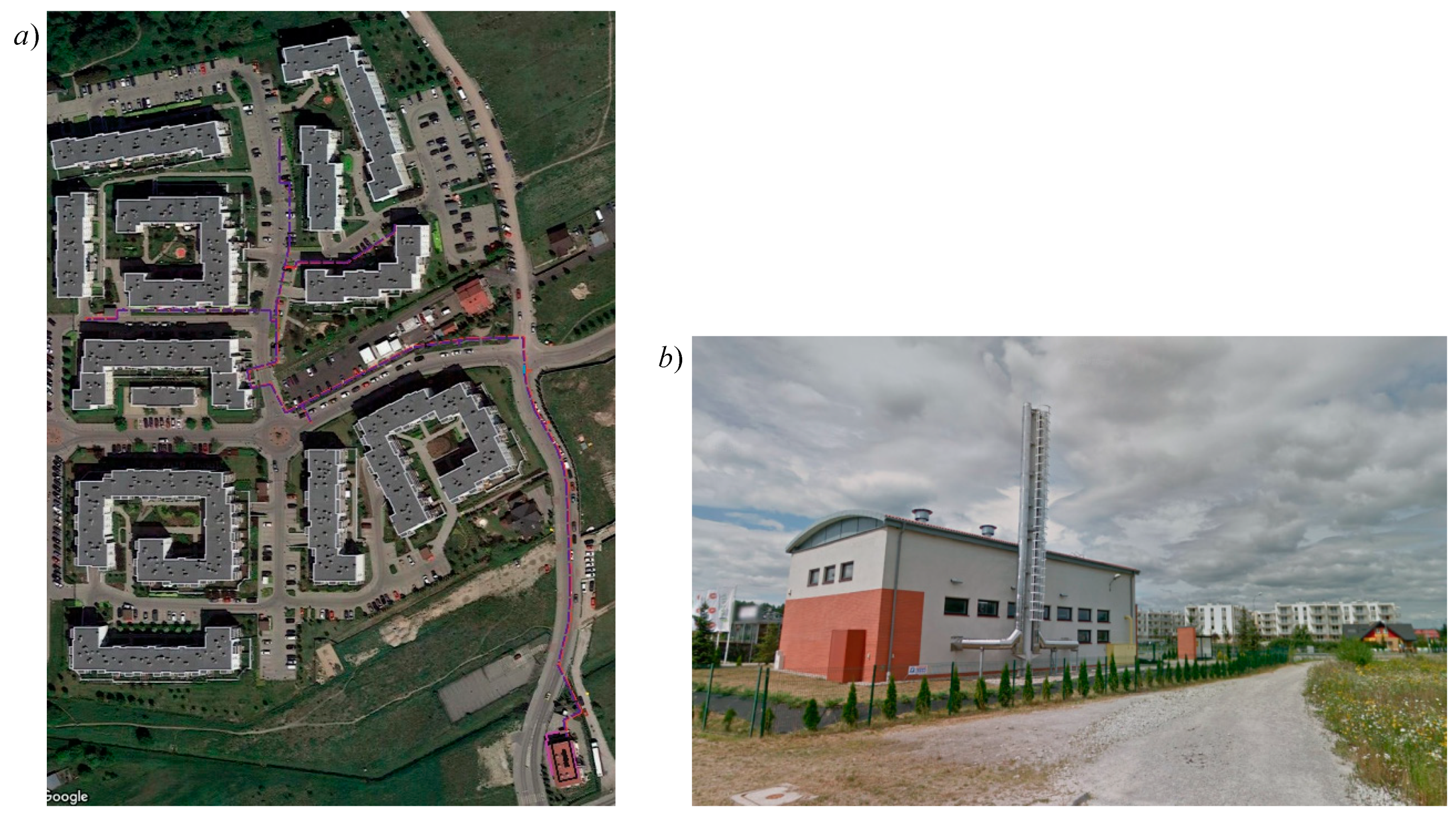
3. Ecological Effect of Modifying Operating Parameters and the Shape of Thermal Insulation of an Existing Pre-Insulated Heating Network Located in Central Poland

The possibilities for the optimization of an existing single pre-insulated network located in Warsaw in central Poland are presented below. The location of the heating network on the satellite image [26] is shown in Figure 4a. The network is supplied by a gas-fired district heating plant (Figure 4b) and provides heat for the heating of buildings during the heating season and domestic hot water (DHW) all year for a small housing estate of multi-family buildings. The network was designed in a few steps, as the estate was expanded and runs along residential streets, as shown in Figure 4a. The analyzed part of the network supplies seven buildings; the total heat load for heating was estimated as 957 kW, while heat load for DHW was estimated as 495 kW [27].
During the heating season, which lasts 255 days, the network operation parameters are TS = 130 °C and TR = 55 °C for the supply and return lines, respectively, whereas, after the heating season, the heating network works only for the purposes of domestic hot water (110 days), and the heating network operation parameters are TS = 70 °C and TR = 25 °C. The heating network operates in the heating season as a high-temperature network, and after the heating season as a low-temperature network. The total length of the network is 553.2 m [27]. The geometry of the network (diameters of heating ducts, diameters of thermal insulation D, length of pipes L, and cross-sectional area of thermal insulation Ati) and flow velocities are presented in Table 1.
Five variants were adopted to examine the ecological effect as follows:
-
Variant A in which the operating temperature of the network was reduced from TS/TR = 130/55 °C to 70/25 °C during the whole year without changes in the geometry of the heating network;
-
Variant B consisting of the replacement of single pipes with double pre-insulated pipes with standard round thermal insulation, maintaining the parameters of 130/55 °C heating network operation in the heating season and 70/25 °C after the heating season;
-
Variant C consisting of the replacement of single pre-insulated pipes with double pre-insulated pipes with standard circular thermal insulation with a temperature reduction as in variant A;
-
Variant D consisting of using egg-shaped thermal insulation pipes with maintenance of 130/55 °C network operation parameters during the heating season and 70/25 °C after the heating season;
-
Variant E consisting of the use of egg-shaped thermal insulation pipes with a temperature reduction as in variant A.
The geometry of a typical twin pipe heating network with round thermal insulation for variants B and C is presented in Table 2. The unit heat losses determined by the boundary element method for the selected diameters of pre-insulated single, double, circular, and egg-shaped thermal insulation networks depending on the average temperature of the heating medium (Tm = (TS + TR)/2) are shown in Figure 5. Heat losses for pipes pre-insulated with circular and egg-shaped thermal insulation depend linearly on the temperature Tm. As the average temperature of the heating medium and the diameter of the duct increase, the heat losses increase. Heat losses in pre-insulated double ducts with circular thermal insulation are on average 41% lower than in the case of single pre-insulated ducts, where, for d = 89.1 mm ducts, heat losses are lower by approximately 31%, while, for d = 219.1 mm ducts, they are lower by 46%. The difference in heat losses between a pre-insulated double duct with a circular thermal insulation for a d = 89.1 mm pipe is in accordance with the calculations in Reference [16].
As in the case of pre-insulated double pre-insulated pipes with circular thermal insulation (Figure 5), the lowest difference between heat losses of single and double pipes with egg-shaped thermal insulation occurs for diameter d = 89.1 mm, and the largest for ducts of diameter d = 219.1 mm. Heat losses in pre-insulated double ducts with egg-shaped thermal insulation are, on average, 51% lower than in the case of pre-insulated single ducts, where, for d = 89.1 mm ducts, heat losses are lower by about 40%, while, for d = 219.1 mm, they are lower by 56%. The difference in heat losses between single and double pre-insulated pipes with egg-shaped thermal insulation is higher by about 3% with the same difference presented in Reference [16]. It should be emphasized that, in Reference [16], the shape of the cross-section of egg-shaped thermal isolation was not described mathematically; therefore, the comparison of the results of calculations of this work with the results of Reference [16] is estimated in the case of the egg shape. The unit heat losses between pre-insulated double-ducts with egg-shaped thermal insulation are about 15.5% lower than in the case of a double duct with circular thermal insulation. This result is better than elliptical [10] and Cassini oval [15] thermal insulations. The main advantage of egg-shaped thermal insulation is the greater thickness of thermal insulation within the supply pipe compared to the return pipe, so that heat losses can be significantly reduced.
When comparing the heat losses in the networks mentioned above, it should be noted that the total area of thermal insulation of the cross-section of the supply and return pipes of single networks (Table 1) is smaller than the cross-section area of double insulated pre-insulated pipes (Table 2). In the case of double pipes, the thermal insulation fields of circular and egg-shaped cross-section are equal.
Table 3 presents the results of calculations of energy losses used for heat losses for the presented heating network. The highest energy consumption for heat losses is carried out by pre-insulated heating networks (existing condition) and is equal to 893 GJ. The reduction of the temperature difference between the supply and return pipes from 130/55 °C to 70/25 °C (variant A) results in a reduction of energy consumption for heat losses by approximately 44%. In variant A, in order to maintain the current heating network performance with a reduced temperature difference of 70/25 °C, the velocity from Table 1 in the existing pre-insulated network should be increased by 44%, resulting in a maximum velocity in the heating network of 1.7 m/s. According to the literature [28], the condition of the optimal velocity in the heating network for variant A is fulfilled. However, it is worthy to note that, in other networks, it could sometimes result in crossing the velocity limit, thereby resulting in the selection of pipes with the higher diameters, which would increase the investment expenditures. The increase in the velocity in the heating network generates greater hydraulic losses, which in turn make it necessary to replace circulation pumps supplying the existing heating network. The reduction of temperatures from 130/55 °C to 70/25 °C also makes it necessary to modernize local heating centers in buildings and central heating installations, and above all to replace radiators with larger ones in order to increase the heat exchange surface. Therefore, this variant is recommended to take into consideration new-build estates with low-energy buildings and new district heating systems, or in cases of integrated investments in the field of thermal retrofitting of buildings envelopes and improvements in HVAC (heating, ventilation, and air conditioning) systems that result in a high reduction of energy consumption [29,30].
In the case of variant B, which consists in modernization by replacing single pre-insulated heating network pipes with double pre-insulated pipes with circular thermal insulation while maintaining the network operation parameters, the energy used for heat losses decreases by approximately 43% compared to the existing single heating network. The reduction of heat losses is slightly lower than that in variant A, whereas the components inside the building do not have to be modernized. The main disadvantage of variant B is the considerable cost of replacing the heating network with double pipe pre-insulated pipes.
Variant C is a combination of variants A and B, related to the replacement of the heating network with the twin pipe type with a simultaneous reduction of network operation temperatures, resulting in energy consumption for heat losses decreasing by 68% compared to the existing single pre-insulated network. The cost of implementing variant C is significant, as it covers both the replacement of the heating network and the modernization of indoor components.
Variants D and E relate to the replacement of an existing pre-insulated single heating network with a pre-insulated double network with egg-shaped thermal insulation. It should be noted here that the proposed pre-insulated heating network with egg-shaped thermal insulation is not used commercially. Variants D and E reduce energy consumption in relation to the current state by approximately 52% and 74%, respectively. From the point of view of reducing heat loss, the best solution is a double heating network with egg-shaped thermal insulation.
The results of calculations of the ecological effect for the assumed variants A–E are presented below. Energy used for heat losses of pre-insulated networks is determined from the product of unit heat losses q, length of pipe L, and time t as follows:
Ecs = qcs × L × t [GJ],
ECase i = qCase i × L × t [GJ],
where the subscript CS denotes the existing state of the pre-insulated network, while subscripts with variant i = A, B, C, D, or E refer to the type of approach.
Reductions in the annual emission of pollutants into the air, as a result of the application of variants (A–E), are calculated according to the following formula:
ΔECase i = (Ecs − ECase i) × Ef [W/m],
where Ef represents the emission factors.
The emission factors nitrogen oxides (NOX), carbon monoxide (CO), non-methane volatile organic compounds (NMVOC), sulfur oxides (SOX), total suspended particles (TSP), particulate matter (PM10 and PM2.5) are based on the literature [31], while carbon dioxide (CO2) and methane (CH4) were adopted from Reference [32] for the combustion of natural gas for heat production. Table 4 shows the emissions of pollutants resulting from the energy consumption for heat losses of pre-insulated networks for the condition of the existing pre-insulated network and the presented variants A–E, while Table 5 presents the reduction of pollutant emissions for variants A–E.
The heat sources in which natural gas is combusted are characterized by much lower emissions of pollutants into the air than other conventional heat sources [31]. Lowering the temperature of the heating network from 130/55 °C to 70/25 °C (variant A) resulted in a significant reduction of emissions to the atmosphere. In the case of carbon dioxide, the annual reduction in carbon dioxide amounted to 32,159.39 kg/year (Table 5). The transition of heating network operation from the high-temperature variant to the low-temperature one significantly improved the ecological effect.
In the case of the replacement of a single pre-insulated network with a double pre-insulated network with circular thermal insulation, while maintaining the existing heating network operation parameters (variant B), the annual reduction of carbon dioxide emission amounted to 21,704.29 kg/year. The ecological effect for variant B is similar to the result of variant A.
In variant C, pollutant emissions were reduced three-fold as compared to the actual operation of the heating network, while variant D allowed twice the reduction of pollutant emissions to the atmosphere in relation to the existing heating network (Table 4).
The best ecological effect was obtained for variant E, where the emission of pollutants into the air was about four times smaller than in the case of the existing single heat-insulated pre-insulated network. The annual reduction of emitted carbon dioxide to the atmosphere in this case amounted to 36,839.74 kg/year.

4. Conclusions

In the presented analysis, the unit heat losses using the boundary element method were calculated first, followed by the energy resulting from heat losses for the exemplary existing heating network, and the reduction of pollutant emissions for the adopted variants were determined. Energy-efficient solutions for heat transport in heating networks undoubtedly constitute a part of modern and ecological heating systems. The reduction of heat losses contributes to the increase of the ecological effect. In this work, a heat loss analysis was performed for different heating system operating temperatures and for two different cross-sectional shapes of thermal insulation of pre-insulated double ducts: circular and egg-shaped thermal insulation. The substitution of high-temperature with low-temperature network operation caused an average reduction in emissions of atmospheric pollutants by about 44%. The deployment of low-temperature networks is recommended in the case of new networks supplying low-energy buildings. However, in the case of existing buildings and networks, before any decision, it is necessary to consider many technical parameters and to estimate costs of modernization in existing systems (for example, replacements of circulation pumps to obtain higher-head pumps, selection of new heat exchangers, or modernization of heating installation with radiators having higher heat exchange surfaces). Therefore, this variant needs a comprehensive cost analysis to be untaken before the decision. The best ecological effect was achieved in the option of low-temperature heating network operation with the change of a single pre-insulated network to a double egg-shaped pre-insulated network, which resulted in a drop in emissions of pollutants into the air by about 74%. The proposed egg-shaped thermal insulation of a double pre-insulated pipe generates less heat losses than typical circular thermal insulations used in double heating lines because it has a larger thermal insulation layer within the supply pipe, where the heat flux density is highest compared to the cross-sectional area of the whole thermal insulation. It should be emphasized that the analysis was carried out for a case study in which only some standard diameters of heating networks were used.
Further studies regarding possibilities to reduce energy consumption and pollutant emission from district heating networks, via optimization of water parameters, thermal storage in the system [33], and new shapes and materials of isolation, are required.

Author Contributions

Conceptualization and selection of the real network for a case study, D.A.K.; simulations and validation, T.J.T.; analysis, T.J.T. and D.A.K.; review of literature, and writing—original draft preparation, T.J.T.; project administration and funding acquisition, D.A.K.

Funding

This study is a part of project VIPSKILLS 2016-1-PL01-KA203-026152 (Virtual and Intensive Course Developing Practical Skills of Future Engineers; Strategic Partnerships Erasmus+).

Acknowledgments

This scientific project was conducted under project WZ/WBiIS/9/2019 at Bialystok University of Technology.

Conflicts of Interest

The authors declare no conflicts of interest.

References

  1. Guelpa, E.; Mutani, G.; Todeschi, V.V. Reduction of CO2 emissions in urban areas through optimal expansion of existing district heating networks. J. Clean. Prod. 2018, 204, 117–129. [Google Scholar] [CrossRef]
  2. Ravina, M.; Panepinto, D.; Zanetti, M.C.; Genon, G. Environmental analysis of a potential district heating network powered by a large-scale cogeneration plant. Environ. Sci. Pollut. Res. 2017, 24, 13424–13436. [Google Scholar] [CrossRef] [PubMed]
  3. Neirotti, F.; Noussan, M.; Riverso, S.; Manganini, G. Analysis of different strategies for lowering the operation temperature in existing district heating networks. Energies 2019, 12, 321. [Google Scholar] [CrossRef]
  4. Boysen, C.; Kaldemeyer, C.; Hilpert, S.; Tuschy, I. Integration of flow temperatures in unit commitment models of future district heating systems. Energies 2019, 12, 1061. [Google Scholar] [CrossRef]
  5. Millar, M.-A.; Burnside, N.M.; Yu, Z. District heating challenges for the UK. Energies 2019, 12, 310. [Google Scholar] [CrossRef]
  6. Lund, H.; Werner, S.; Wiltshire, R.; Svendsen, S.; Thorsen, J.E.; Hvelplund, F.; Vad Mathiesen, B. 4th generation district heating (4GDH) integrating smart thermal grids into future sustainable energy systems. Energy 2014, 68, 1–11. [Google Scholar] [CrossRef]
  7. Kontu, K.; Vimpari, J.; Penttinen, P.; Junnila, S. City scale demand side management in three different-sized district heating systems. Energies 2018, 11, 3370. [Google Scholar] [CrossRef]
  8. Maljkovic, D. Modelling influential factors of consumption in buildings connected to district heating systems. Energies 2019, 12, 586. [Google Scholar] [CrossRef]
  9. Pirouti, M.; Bagdanavicius, A.; Ekanayake, J.; Wu, J.; Jenkins, N. Energy consumption and economic analyses of a district heating network. Energy 2013, 57, 149–159. [Google Scholar] [CrossRef]
  10. Krawczyk, D.A.; Teleszewski, T.J. Optimization of geometric parameters of thermal insulation of pre-insulated double pipes. Energies 2019, 12, 1012. [Google Scholar] [CrossRef]
  11. Van der Heijde, B.; Aertgeerts, A.; Helsen, L. Modelling steady-state thermal behavior of double thermal network pipes. Int. J. Therm. Sci. 2017, 117, 316–327. [Google Scholar] [CrossRef]
  12. Khosravi, M.; Arabkoohsar, A. Thermal-hydraulic performance analysis of twin-pipes for various future district heating schemes. Energies 2019, 12, 1299. [Google Scholar] [CrossRef]
  13. Dalla Rosa, A.; Li, H.; Svendsen, S. Method for optimal design of pipes for low-energy district heating with focus on heat losses. Energy 2011, 36, 2407–2418. [Google Scholar] [CrossRef]
  14. Krawczyk, D.A.; Teleszewski, T.J. Effects of some geometric parameters in energy-efficient heat distribution of pre-insulated double pipes. Proceedings 2018, 2, 1520. [Google Scholar] [CrossRef]
  15. Teleszewski, T.J.; Zukowski, M. Modification of the shape of thermal insulation of a twin-pipe pre-insulated network. AIP Conf. Proc. 2019, 2078, 020030. [Google Scholar]
  16. Bøhm, B.; Kristjansson, H. Single, twin and triple buried heating pipes: On potential savings in heat losses and costs. Int. J. Energy Res. 2005, 29, 1301–1312. [Google Scholar] [CrossRef]
  17. Kudela, L.; Chylek, R.; Pospisil, J. Performant and simple numerical modeling of district heating pipes with heat accumulation. Energies 2019, 12, 633. [Google Scholar] [CrossRef]
  18. Song, S.H.; Cheing, T. Pattern-based set partitioning algorithm for the integrated sustainable operation of a district heating network. Sustainability 2018, 10, 2774. [Google Scholar] [CrossRef]
  19. Yang, W.; Wen, F.; Wang, K.; Huang, Y.; Salam, M.A. Modeling of a district heating system and optimal heat-power flow. Energies 2018, 11, 929. [Google Scholar] [CrossRef]
  20. Sun, G.; Wang, W.; Wu, Y.; Hu, W.; Yang, Z.; Wei, Z.; Zang, H.; Chen, S. A nonlinear analytical algorithm for predicting the probabilistic mass flow of a radial district heating network. Energies 2019, 12, 1215. [Google Scholar] [CrossRef]
  21. Zhao, J.; Shan, Y. An influencing parameters analysis of district heating network time delays based on the CFD method. Energies 2019, 12, 1297. [Google Scholar] [CrossRef]
  22. Danielewicz, J.; Śniechowska, B.; Sayegh, M.A.; Fidorów, N.; Jouhara, H. Three-dimensional numerical model of heat losses from district heating network pre-insulated pipes buried in the ground. Energy 2016, 108, 172–184. [Google Scholar] [CrossRef] [Green Version]
  23. Teleszewski, T.J.; Sorko, S.A. Effect of viscous dissipation on forced convection for laminar flow through a straight regular polygonal duct using BEM method. Int. J. Numer. Methods Heat Fluid Flow 2018, 28, 220–238. [Google Scholar] [CrossRef]
  24. Brebbia, C.A.; Telles, J.C.F.; Wrobel, L.C. Boundary Element Techniques—Theory and Applications in Engineering; Springer: Berlin/Heidelberg, Germany; New York, NY, USA; Tokyo, Japan, 1984; Chapter 2. [Google Scholar]
  25. British Standards Institution. BS EN 253 District Heating Pipes. Preinsulated Bonded Pipe Systems for Directly Buried Hot Water Networks. Pipe Assembly of Steel Service Pipe, Polyurethane Thermal Insulation and Outer Casing of Polyethylene; British Standards Institution: Brussels, Belgium, 2009. [Google Scholar]
  26. Google Maps. Available online: https://www.google.pl/maps (accessed on 1 April 2019).
  27. Krawczyk, D.A. Design of a district heating network from a boiler room to buildings. 2007. [Google Scholar]
  28. Smyk, A.; Pietrzyk, Z. Selection of the optimal pipeline diameter for district heating network. Rynek Energii 2011, 6, 98–105. (In Polish) [Google Scholar]
  29. Krawczyk, D.A. Theoretical and real effect of the school’s thermal modernization—A case study. Energy Build. 2014, 81, 30–37. [Google Scholar] [CrossRef]
  30. Cholewa, T.; Siuta-Olcha, A. Long term experimental evaluation of the influence of cost allocators on the energy consumption in the multifamily buildings. Energy Build. 2016, 104, 122–130. [Google Scholar] [CrossRef]
  31. European Environment Agency. EMEP/EEA Air Pollutant Emission Inventory Guidebook; European Environment Agency, Publications Office of the European Union: Luxemburg, 2016. [Google Scholar]
  32. Gómez, D.R.; Watterson, J.D.; Americano, B.B.; Ha, C.; Marland, G.; Matsika, E.; Namayanga, L.N.; Osman-Elasha, B.; Kalenga Saka, J.D.; Treanton, K.; et al. Intergovernmental Panel on Climate Change (IPCC) Guidelines for National Greenhouse Gas Inventories. Volume 2: Energy, Stationary Combustion. Institute for Global Environmental Strategies; IPCC: Hayama, Kanagawa, Japan, 2006; Chapter 2. [Google Scholar]
  33. Salo, S.; Hast, A.; Jokisalo, J.; Kosonen, R.; Syri, S.; Hirvonen, J.; Martin, K. The impact of optimal demand response control and thermal energy storage on a district heating system. Energies 2019, 12, 1678. [Google Scholar] [CrossRef]
Figure 1. An example of a prototype (a) of a double pre-insulated, egg-shaped thermal insulation pipe made as part of the VIPSKILLS 2016-1-PL01-KA203-026152 project Erasmus+, and boundary conditions (b) adopted for calculating numerical heat losses in the adopted double heating networks.
Energies 12 02104 g001
Figure 2. Temperature field with heat lines (a,b) and heat flux density (c,d) for the double pre-insulated duct in circular (a,c) and egg thermal insulation (b,d) (TS = 130 °C, TR = 55 °C).
Energies 12 02104 g002
Figure 3. Distribution of the heat flux density at the boundary of the cross-section of the thermal insulation of round shape (blue solid line) and egg shape (red dotted line): (a) q = f(x,y); (b) q = f(α).
Energies 12 02104 g003
Figure 4. Location of the presented district heating network in Google Maps “satellite” view (a) and view of a gas-fired district heating plant (b) to which the heating network is connected.
Energies 12 02104 g004
Figure 5. Unit heat loss for different types of pre-insulated pipes as a function of the average supply and return temperature of the heating medium for the studied heating network in northeastern Poland.
Energies 12 02104 g005
Table 1. Geometry and average flow velocity of the heating medium of an existing single pre-insulated heating network.
D (mm)d (mm)L (m)Ati (m2) (Supply + Return)v (m/s)
14076.187.650.0220.5
16088.9127.850.0280.65
225139.766.20.0490.6
250168.31130.0540.95
315219.1158.50.0800.7
Table 2. Geometry for the adopted double pre-insulated heating network with round thermal insulation.
D (mm)d (mm)Ati (m2)
22576.10.031
25088.90.037
400139.70.095
450168.30.115
560219.10.171
Table 3. Energy resulting from heat losses for the existing heating network and the assumed variants of the heating network located in north-eastern Poland.
Description of the Case and Introduced ChangesEnergy for Heat Losses
q (GJ/year)
Current state (ST), single pre-insulated network,
255 (day) (130/55 (°C)) + 110 (day) (70/25 (°C))
893.13
Variant A, single pre-insulated network,
365 (day) (70/25 (°C))
497.36
Variant B, double pre-insulated network with circular thermal insulation,
255 (day) (130/55 (°C)) + 110 (day) (70/25 (°C))
506.25
Variant C, double pre-insulated network with circular thermal insulation,
365 (day) (70/25 (°C))
282.37
Variant D, double pre-insulated network with egg thermal insulation,
255 (day) (130/55 (°C)) + 110 (day) (70/25 (°C))
427.19
Variant E, double pre-insulated network with egg thermal insulation,
365 (day) (70/25 (°C))
236.45
Table 4. Annual emissions of pollutants resulting from energy consumption for heat losses of pre-insulated networks for the condition of the existing pre-insulated network and the presented variants A–E.
PollutantEf (g/GJ)EcsEf (kg/year)EcaseBEf (kg/year)EcaseDEf (kg/year)
255 (day) (130/55 (°C)) + 110 (day) (70/25 (°C))
NOx8979.4945.0638.02
CO3934.8319.7416.66
NMVOC2.62.321.321.11
SOx0.2810.250.140.12
TSP0.890.790.450.38
PM100.890.790.450.38
PM2.50.890.790.450.38
CO256,10050,104.7228,400.4323,965.16
CH410.890.510.43
Ef (g/GJ)EcaseAEf (kg/year)EcaseCEf (kg/year)EcaseEEf (kg/year)
365 (day) (70/25 (°C))
NOx8944.2725.1321.04
CO3919.4011.019.22
NMVOC2.61.290.730.61
SOx0.2810.140.080.07
TSP0.890.440.250.21
PM100.890.440.250.21
PM2.50.890.440.250.21
CO256,10027,902.0315,841.2013,264.98
CH410.500.280.24
Table 5. Reduction of emissions of pollutants into the air as a result of lowering the pre-insulated network operating temperatures and the use of pre-insulated double ducts with circular and egg-shaped thermal insulation instead of single pre-insulated pipes.
PollutantΔEcs-caseA (kg/year)ΔEcs-caseB (kg/year)ΔEcs-caseC (kg/year)ΔEcs-caseD (kg/year)ΔEcs-caseE (kg/year)
NOx35.2234.4354.3641.4758.44
CO15.4415.0923.8218.1725.61
NMVOC1.031.011.591.211.71
SOx0.110.110.170.130.18
TSP0.350.340.540.410.58
PM100.350.340.540.410.58
PM2.50.350.340.540.410.58
CO222,202.6821,704.2934,263.5126,139.5636,839.74
CH40.400.390.610.470.66

