Abstract
Hybrid AC/DC microgrids (HMG) are emerging as an attracting method for integrating AC/DC distributed energy resources (DERs). In the isolated hybrid AC/DC microgrid (IHMG), the key problem is how to balance power variation and regulate voltage and frequency. Various energy storage systems (ESS) and interlinking converter (IC) technologies are viable for this application. The present study proposes a novel unified power flow (PF) model which can be applied to compare and analyze the practical operation modes of the IHMG and, further, to evaluate and compare the abilities of the ESS with different connection topologies and ICs with different control approaches to maintain the voltage and frequency stability of the IHMG. Five operation modes of the IHMG are defined and explained. Then, a set of generic PF equations are derived. Moreover, three binary matrices are applied as input parameters of the unified power equations. These matrices enable a single operation mode of the IHMG at a time to be constructed in the power equation. Finally, the accuracy and effectiveness of the proposed scheme are verified against the time domain simulation result. The quasi-steady-state behaviors of multi-DC subgrids IHMG in different modes after a range of load fluctuation are investigated. The results show that the use of multiple grid-forming units in the AC and DC subgrids, when IC adopted normalized.
1. Introduction
In renewable power generation systems, new features, such as the increment of the DC sources and loads, and rapid developments in DC energy storage systems (ESSs) are emerging. This is more pronounced at the distribution level. In order to satisfy various operational requirements, hybrid AC/DC microgrids (HMG) were introduced. It should be indicated that HMG projects are widely adopted worldwide [1,2,3]. Figure 1 shows a typical topology of the HMG and indicates that the HMG is composed of an AC and a DC subgrid. Each subgrid contains distributed generations (DGs), ESSs, and loads. Moreover, an interlinking converter (IC) links the AC and DC subgrid together.

Figure 1.
Layout of the AC/DC hybrid microgrid (HMG).
Compared to conventional AC or DC microgrids, the hybrid AC/DC microgrid (HMG) reduces the equipment investment and energy loss in the power conversion process by connecting sources and loads to the AC and DC buses with low power consumption for the conversion. It is anticipated that HMGs will be the most promising microgrid structures in the near future [1].
There are two operating modes for the HMG, called the grid-tied mode and the isolated mode. Reviewing the literature shows that the latter mode has recently attracted significant attention because of its desirable characteristics, including the high availability of electricity, profitability for consumers, and electrification potentials for remote isolated small communities. The construction of isolated microgrids has evolved dramatically so far to incorporate DC and hybrid AC/DC systems that can adapt to high penetration of DC-based DGs and loads [3].
Extensive research has been conducted worldwide on the isolated hybrid AC/DC microgrid (IHMG). Most of the research is about power management and control strategy for the IHMG [2,3,4,5,6,7,8,9,10,11,12,13,14,15,16,17,18,19,20,21,22,23,24,25,26,27]. A multilevel hierarchical control is chosen by most authors [2,3,4,5,6]. Guerrero et al. [3] indicated that the hierarchical control usually consists of three levels: local/primary, microgrid/secondary, and global/tertiary, which are described in detail in Section 2. At the primary control level, IHMGs are characterized by an integrated control strategy, where (1) the RESs adopt a maximum power point tracking (MPPT) strategy to achieve as much power as possible; (2) some conventional generators, such as a diesel generator, adopt constant P/Q control and operate in a rated power state [7,8,9,10,11,12,13]; (3) the ESS or inverter-based DGs adopt droop control, performing voltage and frequency control. For the AC subgrid, the output active/reactive power is controlled by regulating the frequency and voltage [14,15]. Similarly, in the DC subgrid, the output power is controlled by adjusting the voltage [16,17,18,19,20]. It is noteworthy that the IC plays a key role to maintain a power balance between the AC and DC subgrids in IHMG. In operation of the IHMG, the location of ESS/droop-controlled DG affects the control strategy adopted by the IC [21]. If the ESS/drooped-controlled DG is located alone in the AC or DC subgrid, the common control method, which connects DG to the grid (such as constant V, constant P/Q control), is adopted by the IC, which means the system frequency and DC voltage will be decoupled. However, if the ESS/drooped-controlled DG is located in both the AC and DC subgrid, the IC uses the normalized droop control method, which relates the AC frequency to the DC voltage to regulate the transferred active power between the AC and DC subgrid. In other words, the AC and DC subgrids are coupled [22,23,24,25,26,27].
The power-flow (PF) analysis significantly contributes to the design, expansion planning, and optimal operation of the HMG [28]. However, in IHMG, various types of control methods for converters and layout plans for components contribute to the diversity and complexity of operation characteristics. Under this situation, the complexity of power flows increases significantly. Researchers modified the conventional methods and developed new approaches for analyzing the power flow. Li et al. [29] implemented the primary control of virtual impedance and droop control into the PF mathematical model. However, the model is performed independently for AC and DC microgrids. Wang et al. [30] presented a PF model which can enable the calculation of voltage characteristics with voltage characteristics containing multiple DC droop control stages. Baradar et al. [31,32] proposed a new PF model by adding a new state variable to handle any kind of converter loss modeling and any kind of converter control method. Ahmed et al. [33] proposed a novel AC–DC PF model for including consideration of the possible AC–DC hybrid distribution network configuration. However, the modeling methods proposed in the above three papers are applicable to analyzing the PF in the voltage source converter high-voltage DC systems.
Hamad et al. [34] and Eajal et al. [35] pointed out the unique operational characteristics of the IHMG: (1) The frequency of the AC subgrid in the IHMG is no longer fixed but changes frequently within a range due to the uncertainty of primary resources, load, and intra-day market factors; (2) because of the development and wide applications of the droop control technology in the IHMG, the new type-droop bus is emerging; and (3) there is the bidirectional power flow between neighboring subgrids. Based on these reasons, a nonlinear power flow methodology and control equations were identified for modeling the IHMG [33,34,35,36,37,38,39]. Studies have shown that there are two general methods for the power flow calculation of the AC/DC hybrid network: the unified method and the sequential methods. Moreover, multiple iterative loops should be solved sequentially and separately in the sequential method, which leads to the increase of computational time and complexity [40]. It should be indicated that this problem is resolved in the unified algorithm [41].
This paper focuses on how to analyze all possible primary operation states of the IHMG considering various types of primary control applied by different converters and various types of layout of units.
Previous research has focused on establishing and solving the IHMG PF and failed to fully consider the impact of the complexity and diversity of primary control strategies and configuration. Based on this, this paper proposed a new unified PF model to the IHMG. The PF analysis for the IHMG can be extended to detail all possible practice steady operation states, based on various types of primary control approach and layout of key units. Unlike secondary and tertiary controllers, which are generally based on similar controllers used in the systems, primary control should be designed specifically for the application in the IHMG [3]. Therefore, multiple running scenarios with different frequency/voltage operation characteristics can be identified according to different primary control strategies. However, reviewing the literature shows that few studies for the IHMG power flow analysis have been performed to date for the diversification of the operational modes of the IHMG. The proposed model is unique from the formulation point of view. Various realistic voltage and frequency control scenarios were considered in the IHMG to unify AC/DC PF equations. The performance of the proposed method was analyzed in independent test cases for the AC and DC microgrids. The developed model employed three binary matrices to describe the configuration and operational mode of the IHMG. The generic AC and DC power equations were constructed. Moreover, the proposed model was used to solve the PF problem. In order to evaluate the effectiveness and accuracy of the proposed mode, the PF results were compared with those obtained from the MATLAB software. The unified PF model proposed in this paper can be used for grid operators to fully understand the characteristics of different operational modes, which have been formed by different quasi-steady-state control strategies in the IHMG. This is more pronounced when the standardization of the supervisory control remains unclear.
The remainder of the presents study is organized as follows: Section 2 provides a brief overview of the hierarchical control for the application of the IHMG and emphatically presents the primary control adopted by grid units of the IHMG. The definitions of the five operational scenario-based control strategies are discussed in detail in Section 3. Section 4 describes the formulation of the proposed PF model, including the unified AC–DC power equations, in detail. The case studies for various operation modes in the IHMG with different configuration and the validation of the proposed PF model are described in Section 4. Finally, Section 5 presents the conclusion of the present study.
2. Primary Control in the Hierarchical Controlled AC/DC IHMG
2.1. Hierarchical Control Level
The ability to support the AC frequency and DC voltage are essential features for the IHMGs when they are disconnected from the main power grid. In fact, there is an obligation for complex control architectures to support the AC frequency and DC voltage. A structured approach using centralized or distributed control is called the multilevel-hierarchical control [2,3,4,5,6]. This structure is extensively applied in low-speed communications. In general, three levels are defined in the hierarchical control strategy:
- Level 1 (primary control): The control object of this level achieves voltage/frequency control for interface devices of the distributed energy resources (DER). Moreover, the power sharing and optimal power management of resources can be obtained;
- Level 2 (secondary control): The control level utilizes the low speed communication network to compensate for the voltage and frequency deviations caused by the primary control level;
- Level 3 (tertiary control): There is a positive response in this control level for external dispatching instructions to maintain the effectiveness, economy, and reliability of the system.
2.2. The Primary Control of the DERs in the IHMG
As the most critical levels in the hierarchical management, there are two distinguished types of primary control levels, namely, the grid-following and grid-forming controls [3]. The purpose of the grid-following control is to extract as much power as possible from the renewable energy resource. For instance, the maximum power point tracking (MPPT) mode in the wind turbine and photovoltaic systems and the operation in the rated power in diesel/biomass generators are practical applications of the grid-following control [8]. Moreover, inverter-based renewable DGs have the capability of reactive power control by means of their inverters. It should be indicated that PV systems and wind turbines are required to participate in some grid codes to provide reactive power control of the power system [8]. The connected buses in the aforementioned resources are usually modeled as PQ buses in the power flow analysis [29].
The grid-forming control, which mostly acts in intentional or non-intentional islanding mode, provides stability of the voltage and frequency. Furthermore, these control strategies fall into two categories based on the need or non-need for communication networks between devices [3]. The former category includes master/slave, central or concentrated control, instantaneous current sharing or circular chain approaches, while the latter one mainly includes the droop-based control and the virtual impedance. Usually, energy storage devices or DGs based on the droop control techniques operate in grid-forming mode [11]. The −P droop of an AC type ESS connected in nth bus can be calculated by Equation (1) [24].
where the subscripts SD, n, and sp denote the ESS units with the droop control, nth AC bus, and the active power droop gain, respectively. Moreover, and are the AC type ESS maximum active power charging and discharging rates, respectively. Furthermore, and denote the frequency at which the ESS starts to charge and discharge at its maximum charging or discharging rates, respectively. Finally, is defined as the following [24]:
The –P and V–Q droop of an AC type DG connects to the nth bus, while the V–P droop of a DC-type DG connects to the mth bus. These are described by Equations (3)–(5), respectively [35,37].
where the subscripts GD, n, and m present the AC-type DG with the droop control, nth AC bus, and mth DC bus, respectively. Moreover, and denote the AC-type active and reactive output power, respectively, and is the DC-type active output power. Furthermore, , , and are the active and reactive droop gain of an AC-type DG and the active droop gain of a DC-type DG, respectively. It should be indicated that , , and are defined by Equations (6)–(8), respectively [35,37]:
Usually, these units are modeled as droop buses during the power flow analysis [10,11,12]. The use of such quasi-steady control characteristics can significantly increase the complexity of the power flow.
2.3. The Primary Control of the IC in the IHMG
As a key element of the IHMG, the IC can achieve the following functions:
- IC can be a slack bus for the AC subgrid, compensating power mismatch in the AC subgrid in the weak systems, while the DC subgrid has a higher power surplus [34]. In this case, the IC can operate in grid-forming mode to perform frequency and voltage control of the AC subgrid;
- IC can be a slack bus for the DC subgrid with lower power surplus capacity than that of the AC subgrid. Moreover, IC can perform voltage control of the DC subgrid as a grid-forming unit in the DC subgrid;
- In order to achieve the equal loadings of subgrids, both subgrids of the IHMG should have similar power when the IC controls the transfer of the active power between the neighboring AC and DC subgrids. Moreover, in order to adapt the active power transfer between the two subgrids, IC measures the AC frequency and DC voltage and equalizes them by normalizing. The corresponding control strategies are as follows:where is the power transferred from the DC to the AC subgrids through the IC in the IHMG.
Since the flow of the active power is from the DC to the AC side, the IC can also support the reactive power at the AC side [30,31]. The injected reactive power of the IC to the AC network through the jth AC terminal is expressed as:
where is the injected active power by the converter at the AC side and and are the apparent and reactive power limits of the IC, respectively.
3. Definition of the Operating Modes in the AC/DC IHMG
3.1. Classification of the AC/DC IHMG Configurations
The structural characteristics of the AC/DC IHMG can be summarized as follows:
- Disconnecting from the main network;
- Connecting the AC and DC subgrids through bidirectional AC/DC interfacing converters (ICs) to fulfill the bidirectional power flow between subgrids;
- Dividing the zones according to the DER type, such as RES, DG and ESS, and load type, such as AC or DC.
Based on the aforementioned classifications, the location of the adopted device for the grid-forming control is closely related to the operating characteristics of the system. Studies [11] have shown that the AC/DC energy storage systems usually operate in grid-forming mode. More concretely, the AC/DC energy storage systems are energy storage devices connected to the AC/DC subgrid. Some devices, like batteries, can be connected to the AC subgrid or to the DC subgrid. The difference is that the corresponding grid-tied converters are controlled differently. Some devices, such as fly-wheel, are suitable for connection to the AC subgrid. The super-capacitors are more suitable for connection to the DC subgrid. Moreover, IC can also maintain the voltage and frequency stability of the IHMG like the ESS. This means that the power difference between the output power of the RES and that of time-variable loads is modified by the output power of the ESS and IC. It should be indicated that loads may vary with time because of a variety of parameters, including weather conditions, prediction error, and so on. The droop control strategies are applied for the application of the AC or DC ESS in accordance with Equation (1). The controlled IC in the constant AC voltage control can maintain the frequency stability in the AC subgrid. Moreover, it can maintain the voltage stability in the DC subgrids in the constant DC voltage control mode. Several network configurations can be found in the literature, which are distinguished by the location of the storage units. Figure 2 shows an HMG system as an example, where its configuration falls into three categories when disconnecting from the utility grid: (1) Storages as grid-forming devices are located only in the AC subgrid; (2) storages are located only in the DC subgrid; and (3) storages are located in both subgrids.
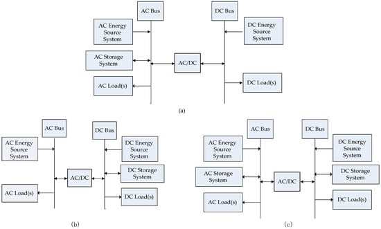
Figure 2.
Classification of the configurations of the isolated hybrid AC/DC microgrid (IHMG) system: (a) Grid-forming units are in the AC subgrid, (b) grid-forming units are in the DC subgrid, and (c) grid-forming units are in both AC and DC subgrids.
3.2. Primary Control Operating Modes
Based on the aforementioned three topological structures, the following five primary control operating modes are identified for the system configuration in accordance with Figure 1.
1. Single grid-forming unit in the AC network:
There is an ESS which operates in the AC network as the grid-forming unit, whereas DGs of both subgrids operate in the grid-following mode. The frequency and voltage of the AC subgrid are sustained by the grid-forming unit, and the voltage of the DC network is regulated with the IC between both networks. Moreover, the DC bus of the IC can operate as the DC slack bus of the DC subgrid.
2. Multiple grid-forming units in the AC network:
More than one storage system is actively involved as grid-forming units, in the control of the voltage and frequency of the AC network of the IHMG. An adequate power sharing strategy of grid-forming units is implemented for balancing the power variations of the IHMG. The method for power management of the DC network is similar to that of mode 1.
3. Single grid-forming unit in the DC network:
In the operating mode, the grid-forming unit and DC energy storage are placed at the DC network. Moreover, the IC establishes the voltage and frequency in the AC network, so its AC bus operates as the AC slack bus of the AC subgrid. The operating principle is the same as that for mode (2).
4. Multiple grid-forming units in the DC network:
Power management is performed in the similar way to that of mode 2. The difference is these grid-forming units control the DC voltage of the DC network while being ensured adequate power sharing between units. The IC establishes the frequency in the AC side.
5. Multiple grid-forming units in both networks:
In the last operating mode, more than one grid-forming unit is placed at both networks. These AC/DC grid-forming units are placed in separate subgrids and can balance the power variations of the whole grid through the IC and transfer the active power between the neighboring two subgrids. The direction of the power flow always transforms into the subgrid with the worst power deficiency. Therefore, no special communication system is required.
Table 1, Table 2 and Table 3 present the corresponding electrical behavior of units in the three main primary control operating modes in the islanded HMG.

Table 1.
The electrical behavior of the main components of IHMG in mode 1.
Table 2.
The electrical behavior of the main components of IHMG in mode 3.
Table 3.
Electrical behavior of the main components of IHMG in mode 5.
4. Formulation of the Unified PF Model
4.1. DER Model
In AC/DC IHMGs, AC-type DERs can operate in three operation modes, including PQ, PV, and the droop modes. Similarly, DC-type DERs can also operate in three modes, including the constant P, constant V, and the droop modes. All modes are defined based on the primary control approach, adopted by the interface conversion of DERs.
In this section, some variables are defined as follows: and are the number of units in the grid-forming control in the AC subgrid (e.g., AC ESS/DGs in the AC droop control) and the DC subgrid (e.g., DC ESS/DGs in the DC droop control), respectively. Moreover, and are the number of units in the grid-following control in the AC and DC subgrids, respectively. On the other hand, and are the total number of buses in the AC and DC subgrids, respectively. The corresponding quantities of various bus connected units are summarized in Table 4.
Table 4.
The variables for the buses of IHMG.
4.2. Formulation of the Unified PF Model
In order to implement the PF model for any generic operational models in accordance with the definitions discussed in Section 3, the system configuration and parameters should be described in a matrix format. The following matrices are defined in this regard. It should be indicated that they are used as inputs for the LF model.
- Unit-type vector W ((N + M) × 1): It describes the unit type (i.e., grid-following or grid forming) connected to the relevant bus in the AC/DC subgrid, as follows:
- (i)
- When = 1, the bus connects to the grid-forming unit;
- (ii)
- When = 0, the bus does not connect to the grid-following unit.
- Judgment vector D ((N + M) × 1): It checks for the coexistence of grid-forming units in both AC and DC subgrids:
- (i)
- When = 1, the grid-forming unit is available in both AC and DC subgrids;
- (ii)
- When = 0, the grid-forming unit is only installed separately in the AC or DC subgrids.
- Judgment vector U ((N + M) × 1): It checks for the existence of the grid-forming unit in each AC or DC subgrid:
- (i)
- When = 1, there are grid-forming units in the AC subgrid;
- (ii)
- When = 0, there is not grid-forming unit in the AC subgrid.
- The AC admittance matrix Y(N N):
- DC conductance matrix : The element in the matrix reflects the value of the conductance of the DC line that connects two buses.
4.3. Power Balance Equations
Power balance equations were derived based on the configuration cases defined in Section 3 and the configuration matrices (W, D, and U). For a given set of elements of the above matrices, only one configuration was activated in the power equations at the same time. The elements of matrices reflect operating modes in the IHMG system, and they are summarized in Table 5.
Table 5.
The values of U, D, and W matrices, corresponding to operating modes of the IHMG.
It should be indicated that when values of the matrix element are equal to those for mode 1 but the number of corresponding nodes is greater than 1, the operating mode of the IHMG is identified as mode 2. Similarly, when values of the matrix element are the same as those for mode 3 but the number of corresponding nodes is greater than 1, the operating mode of the IHMG is identified as mode 4.
The active and reactive power mismatch equations for the buses of AC and DC subgrids of the IHMG system are expressed in Equations (16) and (18), respectively:
Moreover, , , and are expressed in Equations (19) to (21), respectively:
where , and . Moreover, and are the active output power of the AC and DC ESS or DG units in the grid-forming control, respectively. Furthermore, and are the active output power of the AC and DC RES units in the grid-following control, respectively. and indicate the active output power of the AC and DC terminal of the IC, when the IHMG system operates in mode 5. In this paper, the loss of the IC is ignored. Therefore, . On the other hand, , , and denote the output reactive powers of the RES in the grid-following control, DG in the droop control and AC terminal of the IC, respectively.
where, and are the injected active power to the nth AC bus and mth DC bus, respectively. Moreover, and are the magnitude and phase angle of the nkth entry in the AC bus admittance matrix, respectively. denotes the mkth entry of the DC bus conductance matrix, and is the injected reactive power to the mth DC bus, which is expressed as:
In order to summarize the aforementioned equations, the mathematical model of the whole system can be obtained as: F(x) = , where and are describing the mismatch equations of a general AC and DC bus and they are demonstrated as follows:
The Jacobian matrix at kth iteration is defined by:
where:
Variables , are detailed in Table 4.
4.4. Solution Procedure
In order to find the PF solution, a Newton TR dogleg method was employed in the present work. It is a globally convergent iterative method, and it is widely used for solving highly nonlinear equations [42]. The fsolve function of the MATLAB software was used to solve systems of equations by minimizing the sum of squares of the components [43]. It should be indicated that the system of equation is solved when the sum of squares is zero. The fsolve function has three algorithms: trust-region; trust region dogleg, and levenberg-marquardt [44]. The iterative solution procedure of the power flow can be best described by the flowchart in Figure 3.
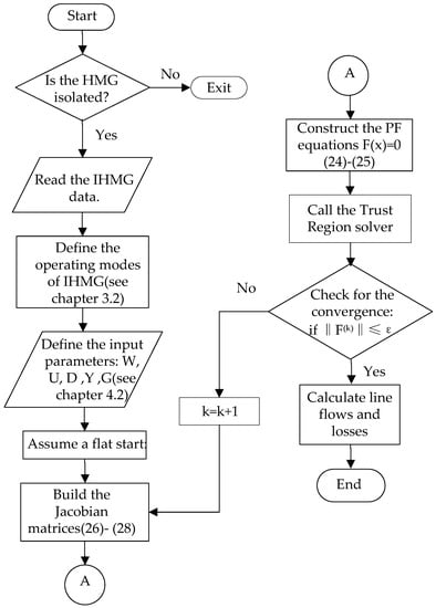
Figure 3.
Flow chart of the proposed mode-adaptive power flow algorithm of IHMG.
5. Cases Studies
There were two case studies conducted in this paper [45]: (1) A 12-bus system was used to verify the accuracy and validity of the algorithm. The output results of the proposed algorithm were contrasted against the steady-state results of a detailed time-domain MATLAB simulation. This comparison was used in [34,35,36,37,38]. (2) The different operational modes of a multi-DC subgrids IHMG were under study. It was intended to investigate the performances of the proposed power flow methods and evaluate the quasi-steady-state behaviors of various primary control strategies. Therefore, the method was applied in main three operational modes after transient events. It should be indicated that considering the derived formulation of the problem, employment of different modes is highly facilitated. The schematic overview of the case studies is shown in Figure 4.
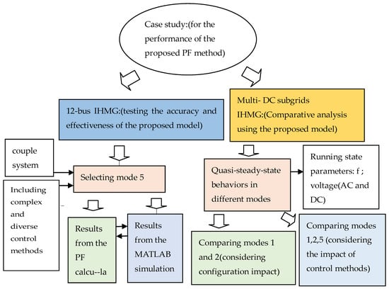
Figure 4.
The schematic overview of case studies.
5.1. Twelve-Bus Test System
The accuracy of the proposed model was verified in comparison with the steady-state solution produced by the MATLAB software. The MATLAB simulation model was directly applied to the existing model proposed in References [23,24,25]. The MATLAB is a time-domain software that utilizes differential equations and can accurately model power system components [43]. Therefore, it can be used for validating LF algorithms [46]. However, such software takes a huge amount of computational time compared to algebraic PF methods so that it should not be applied in steady-state analysis [37].
To test the accuracy and effectiveness of the proposed LF model, it was applied on a 12-bus islanded AC/DC hybrid system, which is a modified test system compared to the one used by Eajal, Mohamed, and El-Saadany [35]. Figure 5 shows the configuration of the test system. The system consists of radial and meshed topologies, a wind turbine, a photovoltaic system, and a DS with droop control as grid-forming units in both the AC and DC subgrids. It should be indicated that both the wind turbine and the photovoltaic system are equipped with MPPT control as grid-following units in the corresponding AC and DC subgrids. Figure 5 indicates that the system is running on mode 5. In this mode, the normalized droop control strategy adopted by the IC promotes the flexible bidirectional power flow between the AC and DC subgrids. This leads to high cooperation of the DGs of the whole system to share the overall loading. However, conventional power flow algorithms fail to accurately simulate the characteristics of the introduced system [35]. In other words, this case study indicates the advantage of the proposed analysis method for the power flow over conventional methods. The MVA and AC/DC KV base values are set to 3.0MW and 2.4/7KV, respectively. The results obtained from the proposed PF model and the steady-state solutions from the MATLAB software are listed in Table 6, Table 7 and Table 8. The data related to generators, IC and corresponding bus classifications are presented in Table 9 and Table 10. Moreover, the impedances of the network and the load connected to the related bus are summarized in Table 11.
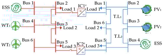
Figure 5.
12-bus IHMG test system operating in mode 5.
Table 6.
Test results of the voltage in the 12-bus IHMG system.
Table 7.
Test results of the output power of the distributed energy resource (DER) in the 12-bus IHMG system.
Table 8.
Test results of the transferred power by interfacing converters (ICs) in the 12-bus IHMG system.
Table 9.
Bus data for the 12-bus IHMG system.
Table 10.
The data for the IC of the 12-bus IHMG system.
Table 11.
Line/Load data for the 12-bus IHMG system.
It was found that the proposed method can solve the power flow in 1.5 s, while the computational time of the MATLAB software is about 20 s. Both the proposed algorithm and the MATLAB software are capable of becoming steady at a frequency of 1.0021 p.u. The maximum bus voltage magnitudes error and the maximum phase error are 0.06% and 0.07%, respectively. These results indicate the accuracy of the proposed method.
5.2. Multi-DC Subgrids IHMG Test System
In this case, modes 1, 2, and 5 of the operation were compared and analyzed. The corresponding test systems are presented in Figure 6, Figure 7 and Figure 8, respectively. They indicate that two identical DC subgrids with identical IC droop constants were connected to the 6-bus AC subgrid. Moreover, the DC subgrid 1 was connected to AC bus 2, whereas DC subgrid 2 was connected to AC bus 5. All AC/DC subgrids were derived from the test system in case 1. In all three operational modes, the sum of ratings of power supplies and one of ESSs of the IHMG system were the same, while the deployment and the primary control approach adopted by each unit was distinct. Figure 6 and Figure 7 indicate that grid-forming ESS unit devices were only configured in the AC subgrid. Moreover, it is observed that the total output power of the WT and the total ESS power rating of the AC subgrids are the same in Figure 6 and Figure 7. However, Figure 6 illustrates that the configuration of the ESS was aggregated because only one unit was placed, and the configuration of the WT is distributed, with two same units placed. Figure 7 shows that the topology of mode 2 is the opposite of that of mode 1. It should be indicated that mode 5 of the operation was also tested in the multi-DC test system.
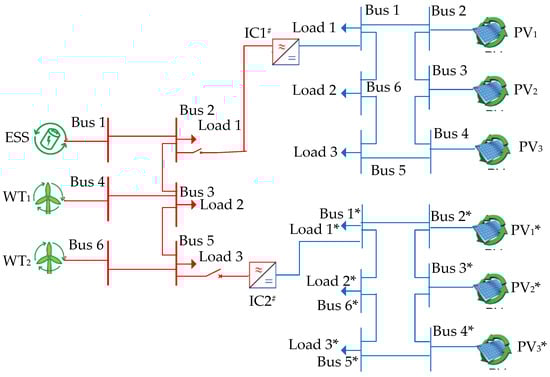
Figure 6.
Multi-DC subgrids IHMG test system in mode 1.
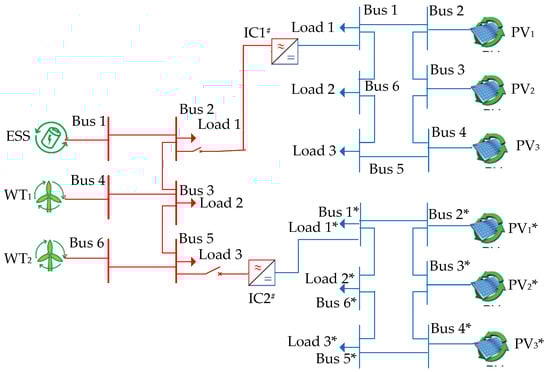
Figure 7.
Multi-DC subgrids IHMG test system in mode 2.
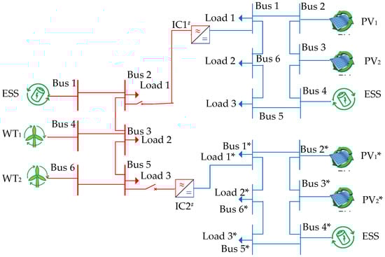
Figure 8.
Multi-DC subgrids IHMG test system in mode 5.
5.2.1. Algorithm Performance in the Normal Potation of the Multi-DC Subgrids System
Figure 9 illustrates the DC bus voltage profile of subgrid 1 in different modes, where subgrid 2 has an identical one.
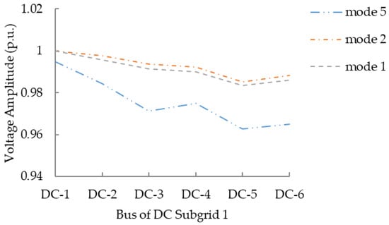
Figure 9.
The DC bus voltage profiles of DC subgrid 1.
The present study intended to investigate the performance of the hierarchical structure, based on the centralized and distributed controls. Modes 1 and 2 were based centralized control, while mode 5 belongs to the distributed control. Figure 9 shows that the general trend of the voltage distribution is consistent in three modes. In mode 2, the voltage deviation was minimum because there were 2 ESS units with distributed connection and lower ESS capacity, compared to that for mode 1. Moreover, it is observed that mode 5 had the maximum voltage deviation. This may be attributed to several reasons, such as: (1) The normalized droop control is adopted by ICs. Therefore, the AC frequency couples with the DC voltage; or (2) there is no slack bus in the system. However, the distributed control has low dependency on the communication and the locations of units in the system. In all modes, the frequency and voltage deviations are compensated by the secondary control, which is not discussed in this study.
5.2.2. Algorithm Performance in the Operation of the Multi-DC Subgrids IHMG System during Load Fluctuation
A series of power flows were solved to evaluate the quasi-steady-state behaviors of the system in different operational modes. Firstly, the AC load at the third bus of the AC subgrid increased from 0 to 0.6 p.u., then the DC load at the sixth bus of DC subgrid 1 increased from 0 to 0.3 p.u. It was intended to investigate the influence of the control method of units on the dynamic characteristics of the IHMG during the load fluctuation on a relatively fast time scale.
Figure 10 illustrates the frequency evolution of the AC subgrid in different modes during AC/DC load fluctuation. AC load fluctuation occurs in the blue region, while DC fluctuation occurs in the yellow region, subsequently. Figure 10 indicates that AC frequency is more affected by the load fluctuation in the distributed control mode 5 in comparison to the centralized control modes 1 and 2. Because the AC terminal of IC adopts the constant, the AC voltage control operates as a slack bus in the AC subgrid in these modes. On the other hand, considering the distributed spatial layout and increasing the number of ESS to 2, although there is the same total capacity in both modes, frequency has a smaller deviation in mode 2 than the one in the mode 1.
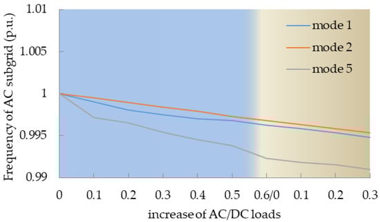
Figure 10.
The distribution of the AC frequency of IHMG for the fluctuating AC/DC load.
Figure 11 presents the evolution of the DC voltage of the sixth bus in DC subgrid 1 and the one of the bus6* in DC subgrid 2 for modes 1 and 2. It was found that when AC load fluctuation occurs, the DC terminal of the IC1 and IC2 is controlled in the constant V mode and it operates as the DC slack bus. Therefore, there was a slight drop in the DC voltage amplitude. Figure 11 indicates that when the DC load increases, the DC voltage amplitude drops. It was observed that the most serious drop occurs in the sixth bus of DC subgrid 1, as the point of load fluctuation. In the no load fluctuation area (i.e., DC subgrid 2), there was a slight drop in DC voltage. Moreover, the ESS units handled power variations of the whole system, while the IC unit handles only the power variations in the DC subgrid in modes 1 and 2.
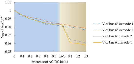
Figure 11.
The distribution of the DC voltage of IHMG for the fluctuating AC/DC load.
It was found that the suppression of voltage deviation in mode 2 is better than the one in mode 1, Because of thedistributed spatial connection of the ESS in mode 2 is better the aggregate connection of the ESS in suppressing power variations.
Figure 12 illustrates the variation of ESS/IC’s performance in the power handling caused by the load fluctuation in modes 1 and 2. In both modes, the IC1 transfers the same power from the AC to the DC subgrid only when the DC load fluctuation occurs. It was found that the IC2 has no power transmission for any DC load fluctuation in the DC subgrid 2. The total output power of the ESS unit is the same in both modes. However, with different spatial configuration, the total output power of the ESS with aggregate connection was averagely allocated two identical ESS units with the distributed connection. It is concluded that the latter is more effective in suppressing the power variation.
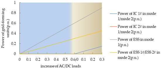
Figure 12.
Distribution of the output power of the ESS/IC in IHMG for fluctuation AC/DC load.
6. Conclusions
ESS and IC units play a decisive role in the frequency and voltage stability of the AC/DC IHMG. In widely applicable hierarchical control architectures, there are various primary control modes adopted by units for maintaining the stable operation of the IHMG. In the present study, a new PF model was proposed for analyzing various operating characteristics of the IHMG system in adopting different primary control methods. The proposed model applies the unified equation and can solve the PF problem for the AC and DC portions of the IHMG simultaneously. Employing three binary matrices as the input parameter of the unified equation, five operation modes of the IHMG with different primary control strategies and component structures are described, which shows the high degree of flexibility of the proposed PF model. The effectiveness of the new PF model was investigated by comparing the calculated results with the simulation solution of the MATLAB software.
It was found that when in the hierarchical structure based on centralized control, the IHMG system displayed more performance in suppression of frequency and voltage fluctuations. However, the spatial layout and the size of the components affect the operation of the IHMG in centralized control. In the hierarchical structure based on distributed control, the IHMG is relatively affected by load fluctuation but still works in a safety boundary. Moreover, the IHMG is slightly affected by the location, size, and deployment of the components in the distributed control. The PF solution enables the use of lower-size and distributed configuration of energy storage systems, and it achieves better effects for suppressing power variations.
In this paper, a deterministic power flow technique for analyzing the steady and quasi-steady operation of the IHMG was proposed. However, considering the intermittent and volatile nature of RESs and inevitable errors in load and generation forecasts, an efficient and robust power flow algorithm is required. Especially, it is necessary to consider the impact of the uncertainty factors of IHMG [47]. Further work is planned for these complexities in IHMG.
Author Contributions
Y.X. conceived the programming, data analysis and writting; X.H. instructed the methodology and writting; C.R. checked the whole manuscript for language editing. P.W. provided the ideas for the paper.
Funding
This research received no external funding.
Conflicts of Interest
The authors declare no conflict of interest.
References
- Wang, P.; Goel, L.; Liu, X.; Ghoo, F.H. Harmonizing AC and DC: A Hybrid AC/DC Future Grid Solution. IEEE Power Energy Mag. 2013, 11. [Google Scholar] [CrossRef]
- Han, Y.; Li, H.; Shen, P.; Coelho, E.A.A.; Guerrero, M. Review of Active and Reactive Power Sharing Strategies in Hierarchical Controlled Microgrids. IEEE Trans. Power Electron. 2017, 32, 2427–2451. [Google Scholar] [CrossRef]
- Guerrero, J.M.; Chandorkar, M.; Lee, T.L. Advanced Control Architectures for Intelligent Microgrids—Part I: Decentralized and Hierarchical Control. IEEE Trans. Ind. Electron. 2013, 60, 1254–1262. [Google Scholar] [CrossRef]
- Vandoorn, T.L.; Vasquez, J.C.; Kooning, J.D.; Guerrero, J.M.; Vandevelde, L. Microgrids: Hierarchical Control and an Overview of the Control and Reserve Management Strategies. IEEE Trans. Ind. Electron. 2013, 7, 42–55. [Google Scholar] [CrossRef]
- Palizban, O.; Kauhaniemi, K.; Guerrero, J.M. Microgrids in active network management—Part I: Hierarchical control, energy storage, virtual power plants, and market participation. Renew. Sustain. Energy Rev. 2014, 36, 428–439. [Google Scholar] [CrossRef]
- Palizban, O.; Kauhaniemi, K.; Guerrero, J.M. Microgrids in active network management—Part II: System operation, power quality and peotection. Renew. Sustain. Energy Rev. 2014, 36, 440–451. [Google Scholar] [CrossRef]
- Abdelaziz, M.M.A.; Ziz, M.M.F.; Farag, H.E.; El-Saadany, E.F. A multistage centralized control scheme for islanded microgrids with PEVs. IEEE Trans. Sustain. Energy 2014, 5, 927–937. [Google Scholar] [CrossRef]
- Nehrir, M.H.; Wang, C.; Strunz, K.; Aki, H.; Ramakumar, R.; Bing, J. A Review of Hybrid Renewable/Alternative Energy Systems for Electric Power Generation: Configurations, Control, and Applications. IEEE Trans. Sustain. Energy 2011, 2, 392–403. [Google Scholar] [CrossRef]
- Eghtedarpour, N.; Farjah, E. Power control and management in a hybrid AC/DC microgrid. IEEE Trans. Smart Grid 2014, 5, 1494–1505. [Google Scholar] [CrossRef]
- Unamunon, E.; Barrena, J.A. Hybrid ac/dc microgrids—Part II: Review and classification of control strategies. Renew. Sustain. Energy Rev. 2015, 52, 1123–1134. [Google Scholar] [CrossRef]
- Aneke, M.; Wang, M. Energy storage technologies and real life applications—A state of the art review. Appl. Energy 2016, 179, 350–377. [Google Scholar] [CrossRef]
- Ahn, S.J.; Park, J.W.; Chung, L.Y.; Moon, S.L.; Kang, S.H.; Nam, S.R. Power-Sharing Method of Multiple Distributed Generators Considering Control Modes and Configurations of a Microgrid. IEEE Trans. Power Deliv. 2010, 25, 2007–2016. [Google Scholar] [CrossRef]
- Bouzid, A.B.; Guerrero, J.M.; Cheriti, A.; Bouhamida, M.; Sicard, P.; Benghanem, M. A survey on control of electric power distributed generation systemsfor microgrid applications. Renew. Sustain. Energy Rev. 2015, 44, 751–766. [Google Scholar] [CrossRef]
- Hossain, M.A.; Pota, H.P.; Issa, W.; Hossain, M.J. Overview of AC Microgrid Controls withInverter-Interfaced Generations. Energies 2017, 10, 1300. [Google Scholar] [CrossRef]
- Nejabatkhah, F.; Li, Y.W. Overview of power management strategies of hybrid ac/dc microgrid. IEEE Trans. Power Electron. 2015, 30, 7072–7089. [Google Scholar] [CrossRef]
- Zhong, Q.C. Robust droop controller for accurate proportional load sharing among inverters operated in parallel. IEEE Trans. Ind. Electron. 2013, 60, 1281–1290. [Google Scholar] [CrossRef]
- Khorsandi, A.; Ashourloo, M.; Mokhtari, H. A decentralized control method for a low-voltage dc microgrid. IEEE Trans. Energy Convers. 2014, 29, 793–801. [Google Scholar] [CrossRef]
- Lu, X.; Guerrero, J.M.; Sun, K.; Vasquez, C. An improved droop control method for dc microgrids base on low bandwidth communication with dc bus voltage restoration and enhanced current sharing accuracy. IEEE Trans. Power Electron. 2014, 29, 1800–1812. [Google Scholar] [CrossRef]
- Piegari, L.; Tironi, E.; Musolino, V.; Grillo, S.; Tornelli, C. DC islands in ac smatrt grids. IEEE Trans. Power Electron. 2014, 29, 89–98. [Google Scholar]
- Dragičević, T.; Lu, X.; Vasquez, J.C.; Guerrero, J.M. DC Microgrids—Part I: A Review of Control Strategies and Stabilization Techniques. IEEE Trans. Power Electron. 2016, 31, 4876–4891. [Google Scholar]
- Unamuno, E.; Barrena, J.A. Primary control operation modes in islanded hybrid ac/dc microgrids. In Proceedings of the IEEE EUROCON 2015—International Conference on Computer as a Tool, Salamanca, Spain, 8–11 September 2015. [Google Scholar]
- Cimuca, G.O.; Saudemont, C.; Robyns, B.; Radulescu, M.M. Controland performance evaluation of a flywheel energy-storage system associated to a variable-speed wind generator. IEEE Trans. Power Electron. 2006, 53, 1074–1085. [Google Scholar]
- Loh, P.C.; Li, D.; Chai, Y.K.; Blaabjerg, F. Autonomous Operation of Hybrid MicrogridWith AC and DC Subgrids. IEEE Trans. Power Electron. 2012, 28, 2214–2223. [Google Scholar] [CrossRef]
- Loh, P.C.; Li, D.; Chai, Y.K.; Blaabjerg, F. Hybrid ac-dc microgrids with energy storages and progressive energy flow tuning. IEEE Trans. Power Electron. 2013, 28, 1533–1543. [Google Scholar] [CrossRef]
- Liu, X.; Wang, P.; Loh, P.C. A hybrid ac/dc microgid and its coordination control. IEEE Trans. Smart Grid 2011, 2, 278–286. [Google Scholar]
- Majumder, R. A hybrid microgrid with dc connection at back to back converters. IEEE Trans. Smart Grid 2014, 5, 251–259. [Google Scholar] [CrossRef]
- Xia, Y.; Peng, Y.G.; Yang, P.C.; Yu, M.; Wei, W. Distributed Coordination Control for Multiple Bidirectional Power Converters in a Hybrid AC/DC Microgrid. IEEE Trans. Power Electron. 2017, 32, 4949–4959. [Google Scholar] [CrossRef]
- Grainger, J.J.; Stevenson, W.D. Power System Analysis, 1st ed.; McGraw-Hill College: New York, NY, USA, 1994; pp. 1–361. [Google Scholar]
- Li, C.L.; Chaudhary, S.K.; Savaghebi, M.S.; Vasquez, J.C.; Guerrero, J.M. Power Flow Analysis for Low-Voltage AC and DC Microgrids Considering Droop Control and Virtual Impedance. IEEE Trans. Smart Grid 2017, 8, 2754–2764. [Google Scholar] [CrossRef]
- Wang, W.; Barnes, M. Power Flow Algorithms for Multi-Terminal VSC-HVDC With Droop Control. IEEE Trans. Power Syst. 2014, 29, 1721–1730. [Google Scholar] [CrossRef]
- Baradar, M.; Ghandhari, M. A Multi-Option Unified Power FlowApproach for Hybrid AC/DC Grids Incorporating Multi-TerminalVSC-HVDC. IEEE Trans. Power Syst. 2013, 28, 2376–2383. [Google Scholar] [CrossRef]
- Baradar, M.; Ghandhari, M.; Hertem, D.V. The modeling multi-terminal VSC-HVDC in power flow calculation using unified methodology. In Proceedings of the 2011 2nd IEEE PES International Conference and Exhibition on Innovative Smart Grid Technologies, Manchester, UK, 5–7 December 2011. [Google Scholar]
- Ahmed, H.M.A.; Eltantawy, A.B.; Salama, M.M.A. A Generalized Approach to the Load Flow Analysis of AC–DC Hybrid Distribution Systems. IEEE Trans. Power Syst. 2017, 33, 2117–2127. [Google Scholar] [CrossRef]
- Hamad, A.A.; Salama, M.M.; EL-Saadany, E.F. A Novel Load Flow Algorithm for Islanded AC/DC Hybrid Microgrids. IEEE Trans. Smart Grid 2019, 10, 1553–1566. [Google Scholar]
- Eajal, A.A.; Mohamed, A.A.; El-Saadany, E.F. A Unified Approach to the Power Flow Analysisof AC/DC Hybrid Microgrids. IEEE Trans. Sustain. Energy 2016, 7, 1145–1158. [Google Scholar] [CrossRef]
- Aprilia, E.; Meng, K.; Hosani, M.A.; Zeineldin, H.H. Unified Power Flow Algorithm for Standalone AC/DC Hybrid Microgrids. IEEE Trans. Smart Grid 2019, 10, 639–649. [Google Scholar] [CrossRef]
- Hamad, A.A.; Azzouz, M.A.; Saadany, E.F.E. A Sequential Power Flow Algorithm for Islanded Hybrid AC/DC Microgrids. IEEE Trans. Power Syst. 2016, 31, 3961–3970. [Google Scholar] [CrossRef]
- Aprilia, E.; Meng, K.; Dong, Z.Y.; Jia, Y.W.; Xu, Z. Hierarchical power flow algorithm for standalone hybrid AC/Multi-DC microgrids. In Proceedings of the 2017 IEEE Power & Energy Society General Meeting, Chicago, IL, USA, 16–20 July 2017. [Google Scholar]
- Golsorkhi, M.S.; Lu, D.D.C. A decentralized power flow control method for islanded microgrids using V-I droop. In Proceedings of the2014 22nd Iranian Conference on Electrical Engineering, Tehran, Iran, 20−22 May 2014. [Google Scholar]
- Beerten, J.; Cole, S.; Belmans, R. A sequential AC/DC power flow algorithm for networks containing Multi-terminal VSC HVDC systems. In Proceedings of the IEEE Power and Energy Society General Meeting, Providence, RI, USA, 25–29 July 2010. [Google Scholar]
- Narayanan, K.N.; Mitra, P. A comparative study of a sequential and simultaneous AC-DC power flow algorithms for a multi-terminal VSC-HVDC system. In Proceedings of the 2013 IEEE Innovative Smart Grid Technologies-Asia, Bangalore, India, 10–13 November 2013. [Google Scholar]
- Nocedal, J.; Wright, S.J. Numerical Optimization, 2nd ed.; Springer: New York, NY, USA, 2006; pp. 66–91. [Google Scholar]
- Chen, Y.C.; Dong, P.; Wu, Z.D. Analysis of power flow in wind farm with matpower. In Proceedings of the 2017 7th International Conference on Power Electronics Systems and Applications—Smart Mobility, Power Transfer & Security, Hong Kong, China, 12–14 December 2017. [Google Scholar]
- Zimmerman, R.D.; Daniel, R.; Murillo-Sanchez, C.E.; Thomas, R.J. MATPOWER: Steady-State Operations, Planning, and Analysis Tools for Power Systems Research and Education. IEEE Trans. Power Syst. 2011, 26, 12–19. [Google Scholar] [CrossRef]
- IEEE Guide for Design; Operationand Integration of Distributed Resource IslandSystems with Electric Power Systems; IEEE Std.: Piscataway, NJ, USA, 2011; pp. 1–54.
- Pogaku, N.; Prodanovic, M.; Green, T.C. Modeling, analysis and testing of autonomous operation of an inverter-based microgrid. IEEE Trans. Power Electron. 2007, 22, 623–625. [Google Scholar] [CrossRef]
- Hosseinzadeh, M.; Salmasi, F.R. Robust optimal power management system for a hybrid AC/DC micro-grid. IEEE Trans. Sustain. Energy 2015, 3, 675–687. [Google Scholar] [CrossRef]
© 2019 by the authors. Licensee MDPI, Basel, Switzerland. This article is an open access article distributed under the terms and conditions of the Creative Commons Attribution (CC BY) license (http://creativecommons.org/licenses/by/4.0/).