Wake Effect of a Horizontal Axis Wind Turbine on the Performance of a Downstream Turbine


1
Department of Bridge Engineering, Southwest Jiaotong University, Chengdu 610031, China
2
Department of Civil and Environmental Engineering, The Hong Kong University of Science and Technology, Clear Water Bay, Kowloon, Hong Kong, China
3
CLP Power Wind/Wave Tunnel Facility, The Hong Kong University of Science and Technology, Clear Water Bay, Kowloon, Hong Kong, China
*
Author to whom correspondence should be addressed.
Energies 2019, 12(12), 2395; https://doi.org/10.3390/en12122395
Submission received: 13 May 2019
/
Revised: 18 June 2019
/
Accepted: 19 June 2019
/
Published: 21 June 2019
(This article belongs to the Special Issue Recent Advances in Aerodynamics of Wind Turbines)
Abstract
:This paper presents wind tunnel tests on the wake characteristics of a three-blade horizontal axis wind turbine and the wake effect on the performance of a downstream turbine. For a single turbine model, the performance was determined and this was followed by measurement of the wind characteristics including velocities, turbulence intensities, and correlation in the wake flow field. Subsequently, taking two horizontal axis wind turbines in a tandem arrangement into account, their performance was tested and the aerodynamic mechanism was discussed. The results showed that the upstream turbine with blades set at a small pitch angle provided smaller disturbance to the flow, but as the blade turned faster, larger changes in the velocity and the turbulence intensity occurred in its wake due to the more frequent disturbance of the wind turbine. The correlation of wake velocities in the turbine swept area also obviously decreased from the free-stream situation. For the downstream turbine, the output power loss largely depended on the wake characteristics of the upstream turbine, which was closely related to lower wind velocities or higher turbulence intensities. The decrease in correlation of the streamwise velocity within the blade swept area is accompanied by the increased correlation of the tangential velocity, which may be beneficial to the downstream turbine’s performance.
1. Introduction
In the modern era, environmental pollution, climate change, as well as the energy crisis are big challenges for the whole of mankind. Wind energy, as a renewable and clean energy, is one of the most profitable energy sources and has attracted great attention. There are basically two types of wind turbines according to their hub direction, namely, the horizontal axis wind turbine (HAWT) and the vertical axis wind turbine (VAWT). The three-blade horizontal axis turbine, which has a relatively large efficiency, has been widely implemented and the principle of its performance is briefly introduced here. There have been numerous wind tunnel tests, numerical simulations, and field experiments related to research on HAWTs and many remarkable achievements have been made.
The power coefficient is a key index to describe turbine performance and is closely related to the tip speed ratio (TSR). The TSR represents the rotational speed of the turbine to the wind velocity and is affected by the aerodynamic shape of the blades, such as the pitch angle. Many researchers have been trying to optimize the shape of the blade and improve the power coefficient of the HAWT in different ways. Through wind tunnel tests, Xie et al. [1] studied the performance of a pitch-regulated three-blade wind turbine model with a small size. Apart from the ability to adjust the power coefficient, the innovative blade design was also capable of adjusting the blade operating TSR in the range between 2.94 and 6.45 for the unfolded blade and between 1.07 and 2.55 for the 40° folded angle. Xie et al. [2] investigated the aerodynamic performance of an umbrella-type wind turbine using experimental and theoretical methods and showed that the power coefficient and TSR of this turbine drop significantly when its blades are folded. Sutrisno et al. [3] tested a small-scale wind turbine with a designed TSR of 3.65 and considered two types of blades, with one having a backward swept at the tip and the other a helicopter-head tip. The tested results were further used to estimate the power generation of a real-scale turbine. With computational fluid dynamics (CFD) simulations, Lee et al. [4] studied the aerodynamic performance of a wind turbine with two different blades. One blade design was based on the blade element momentum theory and its maximum power coefficient was 0.469 at a TSR of 5.61. The other design was a non-twisted type with an unchanged chord length, and the maximum power coefficient of this type was 0.3 at TSR 5.08. Lin et al. [5] studied a 150 kW wind turbine and found the maximum power coefficient at 0.42, which was achieved with a blade at a 5° pitch angle and a TSR of 3.6. With field experiments, Li et al. [6] studied a 30 kW wind turbine with a rotor diameter of 10.0 m and a hub height of 13.4 m, and the maximum power coefficient was 0.35 at a TSR of 7.5. Howard and Guala [7] studied the effects of turbulent flow conditions on the performance of a 2.5 MW wind turbine with an optimal TSR of approximately 8.5, and the blockage effect on the mean wind speed profile of the incoming flow was found.
Although wind tunnel testing can provide an effective and reliable way to predict the performance of a wind turbine, reduced-scale turbine models have to be used due to the limited sizes of wind tunnels. There is inevitably a large difference in the Reynolds numbers between the real-sized turbine and the model turbine. This Reynolds number effect may affect the scaling of experimental results from the model scale to the full scale. The Reynolds number is usually expressed as , where is the incident wind velocity; is the chord length of the airfoil; and is the kinematic viscosity. Chamorro et al. [8] suggested that stronger Reynolds number dependence occurs in the near wake region, while the main flow statistics become independent of Reynolds number starting from . Park et al. [9] showed that the power coefficient of a wind turbine is very sensitive to the change in the model scale, but the thrust coefficient is not. Ge et al. [10] selected six airfoils and found they all exhibited better performance at a higher Reynolds number. Li et al. [11] studied the Reynolds number effect on four thick airfoils at two different wind tunnels and found that increasing makes the separation point move towards the leading edge. Tarhan and Yilmaz [12] investigated the Reynolds number effect on the lift, drag, and lift/drag coefficients of 14 small wind turbine airfoils with both wind tunnel tests and numerical simulations. Meanwhile, the Reynolds number effect on VAWTs has also received much attention [13,14]. With the increase in rotor size, the difference in the Reynolds numbers between the real-sized turbine and the model turbine becomes more obvious and its effect could not be omitted.
Using multiple turbines in a wind field is a major trend used to generate more energy due to the limited land resources. However, downstream turbines usually have to operate in the wake of upstream turbines, which leads to tremendous power losses. The wake effect loss must be taken into account when calculating the efficiency of large offshore wind farms [15], and the average power loss due to the wind turbine wake is on the order of 10% to 20% of the total power output [16]. Meanwhile, small changes in wind direction, i.e., yaw angle, have strong impacts on the total power output [17]. Therefore, it is of great importance to understand the wake characteristics of a turbine and the wake effect on the performance of a downstream turbine to arrange them reasonably and efficiently. Apparently, the wake characteristics of an upstream turbine are closely related to its own TSR, and so is the performance of a downstream turbine. Medici and Alfredsson [18] suggested that the near wakes produced by wind turbines with similar TSRs show very similar characteristics. Hu et al. [19] investigated the evolution of vortices in the near wake of a turbine and the structure of the turbulent flow field. The TSR of the turbine model varied from 0 to 4.5, and the largest velocity deficit in the wake flow was observed at a TSR of approximately 3. Zhang et al. [20] showed that the near-wake region is characterized by high three-dimensionality, turbulence heterogeneity, and strong flow rotation. Bastankhah and Porté-Agel [21] predicted the wake characteristics of a yawed wind turbine, and the velocity measurement indicated that the wake velocity deficit becomes smaller and the wake deflection increases with the increase in yaw angle. Qian et al. [22] also showed that yaw misalignment has significant influence on the performance of a turbine as well as its wake. Chu and Chiang [23] studied the turbulent effect on wake characteristics and power production of a wind turbine and found that the power loss could be larger than 50%. On the other hand, researchers have been trying to improve the performance of the downstream turbine. Adaramola and Krogstad [24] found that the loss in the maximum power coefficient of the downstream turbine is mainly between 20% and 45%. When the upstream turbine is operated in a yawed inflow condition, the total power output from two wind turbines in a tandem arrangement is increased by about 12%. Considering the effect of a yaw angle as well, Bastankhah and Porté-Agel [25] studied the interaction of a turbulent boundary layer with a wind turbine operating under different TSRs. Talavera and Shu [26] found that the maximum power coefficient of a single turbine could significantly increase from 0.125 under laminar inflow to 0.345 under turbulent inflow. A similar phenomenon was observed for two turbines in a tandem arrangement.
While the aforementioned studies have improved our understanding of the performance and wake characteristics of three-blade horizontal axis turbines, the mechanism of how a turbine’s wake affects the performance of another turbine has not yet been fully explored. In addition to a reduction of the wind velocities in the wake, other possible turbulence effects influencing the performance of the downstream turbine are seldom studied. For instance, the possibly altered spatial correlation of wind speeds in the turbine wake would affect the instantaneously available kinetic energy for the downstream turbine. Hence, in this study, wind tunnel tests were carried out to determine the wake characteristics of a three-blade HAWT. In particular, wind velocities, turbulence intensities, and spatial correlation coefficients in the wake with different TSRs were measured and analyzed. The instantaneous flow field behind the turbine was obtained by particle image velocimetry (PIV). The second part of the study focused on the effects of these characteristics on the performance of another downstream turbine.
2. Wind Tunnel Experiments
2.1. Experimetal Setup
Wind tunnel tests were conducted at the CLP Power Wind/Wave Tunnel Facility at the Hong Kong University of Science and Technology. The high-speed test section, which has a cross-section of 3 m wide by 2 m high and a fetch of approximately 28 m, was selected.
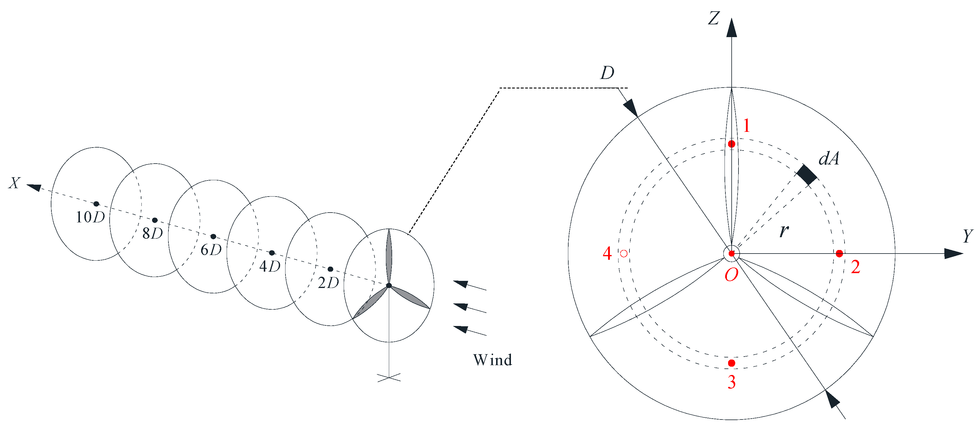
The horizontal axis wind turbine (HAWT) models used in the experiments were acquired from Horizon Educational. The wind turbine consisted of three blades at 120° from each other. The width of the blade chord was 30 mm and the blade profile was designed based on NASA aeronautics, with more details available from the website: www.horizoneducational.com or the authors. The root pitch angle of the blade could be adjusted within a range from 0° to 45°. The diameter of the rotor plane D was 360 mm, so the turbine blade swept area was about 0.102 m2. The corresponding blockage ratio of the blade swept area to the cross-sectional area of the tunnel was less than 2%. The length of the turbine nacelle was 160 mm and the distance from the hub axis to the tunnel ground was 285 mm. A small electric generator was installed inside the nacelle. According to the direction of incoming flow, the axial, lateral, and vertical directions were defined as x-, y-, and z-axes, respectively, as shown in Figure 1, and the hub center was set as the origin of the coordinate system.
The wake characteristics of the HAWT model were measured using cobra probes (Turbulent Flow Instrumentation Pty. Ltd., Tallangatta, Australia) and a PIV system. The cobra probe is a multi-hole pressure probe which can measure the three components of turbulent velocity. The sampling frequency was set to 2000 Hz to resolve turbulent fluctuations of wind velocities in the wind tunnel. For PIV measurement, a thin laser sheet was generated from a double-cavity Q-switched Nd:YAG laser (Nano 50–100, Litron, Rugby, UK). The laser sheet illuminated the central vertical (x-z) plane of the turbine wake, in which the fluid velocities were marked with fine seeding particles in an oil mist generated by a high-volume liquid seeding generator (10F03, Dantec Dynamics, Skovlunde, Denmark). Double-frame flow images were captured by a high-speed CMOS camera (SpeedSense, Dantec Dynamics, Skovlunde, Denmark) which had a high sensitivity for the weak scattered light signals. The time interval between the double laser pulses was set to 0.2 ms to fix the initial and final positions of seeding particles in a double image. Wake characteristics were computed from the double images using the adaptive cross-correlation PIV algorithm [27,28].
2.2. Performance of a Single HAWT
Wind is the movement of air mass. After passing through a wind turbine, the velocity will drop, and the power captured by the turbine can be expressed as
where is the power coefficient of the turbine; is the air density; is the rotor diameter; and is undisturbed wind velocity at the same height of the hub axis.
In the wind tunnel tests, the output voltage was measured to calculate the power generation, and thereby was obtained by Equation (1). describes the turbine performance and is closely related to the TSR determined by Equation (2) and the pitch angle of blade.
where n is the revolution per minute (RPM) of the wind turbine. For a variable-pitch wind turbine, starting and parking can be easily achieved by adjusting the pitch angle, and it can also be used to stabilize the output power above the rated wind speed.
The effect of the root pitch angle on the TSR was first studied. The incoming flow was kept unchanged with at 4.4 m/s and a turbulence intensity of approximately 5% at the height of hub axis. Different root pitch angles ranging between 0° and 45° were considered, and the RPM of the wind turbine was measured by a digital laser tachometer. The results are listed in Table 1. When is small, the blade causes less disturbance to the incoming flow, thus it rotates faster. With an increase in , the flow resistance to the blade increases so decreases, leading to a reduction of the power coefficient. However, the relationship between and is not a linear trend, and is more sensitive to the change of when it is between 7.5° and 22.5° (see Figure 2).
Subsequently, the root pitch angles of 7.5°, 15°, and 22.5° were selected for further testing, where the wind velocity varied between 2 m/s and 10 m/s. For a more convenient comparison, the power coefficients of the wind turbine with different root pitch angles and different wind velocities are normalized by the maximum value. Figure 2 shows the relationship among RPM, , and the normalized power coefficient . For a fixed blade angle, both the RPM and the TSR of the wind turbine increase with increasing wind velocity. The RPM of the wind turbine increases with a TSR at a faster rate when the TSR is larger than its optimum value. With the increase in , the normalized power coefficient first increases rapidly to reach a peak value at an optimum value, beyond which decreases gradually with the RPM.
3. Wake Characteristics of a Single HAWT
In this section, three root-pitch angles were used in the wind tunnel tests, i.e., 7.5°, 15°, and 22.5° among which the turbine performance changed significantly. The wind velocity of the incoming flow () was fixed at 4.4 m/s, and the corresponding TSRs of the wind turbine with the three root-pitch angles were 3.5, 2.5, and 1.8, respectively. It should be noted that the Reynolds number for the turbines in the experiments was 8.8 × 10³, which was much smaller than those in most commercial wind tunnel installations. Even though the Reynolds number effect should be significant, as discussed in Section 1, the primary wake characteristics behind the turbine may be reproduced with less inaccuracy at relatively low Reynolds numbers [18,20].
3.1. Wake Recovery
Three-component flow velocities in the wake of the turbine were measured by a cobra probe, which could resolve the turbulent part of the velocity signals. For each measurement position, the velocity was measured at a rate of 2000 Hz for a sampling time of 60 s. The characteristic time scale of the flow past the turbine () was about 0.08 s, so that the sampling time was sufficient to obtain statistically stable measurements. The measurement was taken within a region from 0.5 D to 12 D in the horizontal direction (x-direction, as shown in Figure 1) and from the tunnel floor level to 1.5 D in the vertical direction (z-direction). The streamwise velocity averaged over the sampling time at a point in the turbine wake was named . Along the hub axis, the change in the ratio of to is shown in Figure 3a. At the axial stations of X/D = 2, 4, 6, 8, and 10, the change in the ratio of to along the z-direction is shown in Figure 3a as well. The streamwise turbulence velocity was computed from the standard deviation of the turbulent part of the streamwise velocity signal, from which the streamwise turbulence intensity was calculated by Equation (3), shown in Figure 3b.
where T is the measurement time; N is the total number of a sample at a certain measurement position; and is the instantaneous streamwise velocity at a certain time.
The results in Figure 3 show that, after passing through the turbine, the velocity of incoming flow decreased but the turbulence intensity increased. A small pitch angle produced smaller disturbances to the flow, but the blade turned faster, leading to larger changes in the wind velocities and turbulence intensities in the wake due to the more frequent disturbances of the wind turbine. As a result, the decreasing range of wake velocities and the increasing range of turbulence intensities were both the largest for the TSR of = 3.5, which was obtained with = 7.5°. At this situation, the wind velocity in the wake decreased first and then recovered slowly with the increase in X/D. The turbulence intensity showed an increasing trend when X/D was less than 4, and then it decreased. It is important to note that even when the downstream distance increased to X/D = 12, the wake velocity only recovered to 0.83 and the turbulence intensity was still obviously larger than that of the incoming flow. At the smaller TSRs of 2.5 and 1.8, the variations of the wind velocity and the turbulence intensity with X/D show monotonically increasing and decreasing trends, respectively. The rotation of the blades became slower with the increase in to 15° and 22.5°. Therefore, the turbine absorbed less energy from winds and exerted smaller effects on its wake. Wind velocities and turbulence intensities in the wake were less affected, and they recovered faster as well, as compared to the case for = 7.5°. At the position of X/D = 12, the wind velocity was slightly smaller than that of the incoming flow and the turbulence intensity was slightly larger.
In the transverse vertical (y-z) plane, the wake effect generated by the wind turbine within its swept area is obvious from Figure 3. The wake effect on the wind velocity was the greatest around the hub axis, while the wake effect on the turbulent intensity was obvious near the blade tip, especially for the upper side. Both the effects decreased progressively when going radially outwards. With the increase in X/D, the decreasing range of the wind velocity and the increasing range of the turbulent intensity became small, but the flow field affected by the wind turbine became broader due to the growth of the wake width. Compared with the region above the hub axis, the wake below the turbine hub had smaller velocities with larger turbulent intensity due to the presence of the ground.
The mean flow field of the turbine wake on the central x-z plane (y = 0) through the turbine hub was also measured by PIV. Considering the fact that the measurement area of the PIV camera was only 390 mm in length and 255 mm in height, the root pitch angle was set as 45° because the wake of the turbine with this lower TSR could recover faster. The results are shown in Figure 4.
In Figure 4, the PIV measurement was made at four measurement areas and the measurement data were combined to obtain the flow field in an investigation region covering an axial distance from 0D to 1.8D along X direction and a vertical distance from −0.7D to 0.6D along z-direction. Figure 4a shows the contour map of and Figure 4b shows the contour map of . Compared to the results with larger TSRs (see Figure 3), the wake fields of the turbine with the smaller TSR show similar features in that the decreases behind the turbine hub and is accompanied by increased but with a shorter distance for wake recovery. In Figure 4a, the contour lines indicate that the largest wake velocity deficit originated from the turbine nacelle and the region of velocity deficit extended farthest around the hub axis. In the region above the hub axis, the separation among adjacent contour lines increased with the increase in distance from the hub. However, the recovery rate became smaller as the wake recovered and the velocity increased. In the region below the hub axis, the velocity deficit was more significant due to the ground roughness and the disruption of the supporting pole. In Figure 4b, was relatively large behind the turbine hub but it recovered quite fast. In addition, large turbulence intensities were also observed on going nearer to the ground surface. Very large values of were found in a region behind the supporting pole, but there appeared to be some PIV measurement errors here due to the poor lighting problem.
Figure 4c shows the contour map of where is the mean vertical velocity. Compared with the streamwise velocities, the were very small implying that the air flow remained approximately horizontal in the turbine wake. There was no obvious pattern in the contour map, but in most of the study area, was negative, i.e., downwards, but near to the ground surface it was positive. Within the zone just behind the turbine and beneath the hub axis, the downward vertical velocity was relatively large, which was also the zone where the streamwise velocity deficit was also the largest.
Figure 4d shows the contour map of the normalized turbulent kinetic energy which was obtained from the planar PIV data as and then normalized by , where is the vertical turbulent velocity. Although not shown, the contour map of had a similar distribution pattern as , but of slightly smaller values. It can be seen in Figure 4d that high turbulent energy was found behind the supporting pole and near the ground, while the region behind the turbine hub had lower energy. This may be due to the more streamlined flow over the turbine hub.
3.2. Wake Correlation
One focus of this paper was to understand the change in spatial correlation of the fluctuating wind speeds in the turbine wake and whether this would affect the performance of the downstream turbine. For this purpose, two cobra probes were used for measuring the wind velocities simultaneously at two positions in the wake. One was placed at a fixed position, that is, the reference position p, and the other was moved along y- or z-direction, that is, the measurement position m. The sampling time was also set to 60 s with a sampling frequency of 2000 Hz. Two sets of correlation measurements were made, with the reference position was placed at a position downstream of the hub axis or the blade tip, as shown in Figure 5. The correlation coefficient with respect to the two positions was calculated by:
where ranging from −1 to 1 is the correlation coefficient between time histories of the two fluctuating wind velocities at positions m and p; and are the standard deviations of the two histories; and is their co-variance during the sampling time of 60 s.
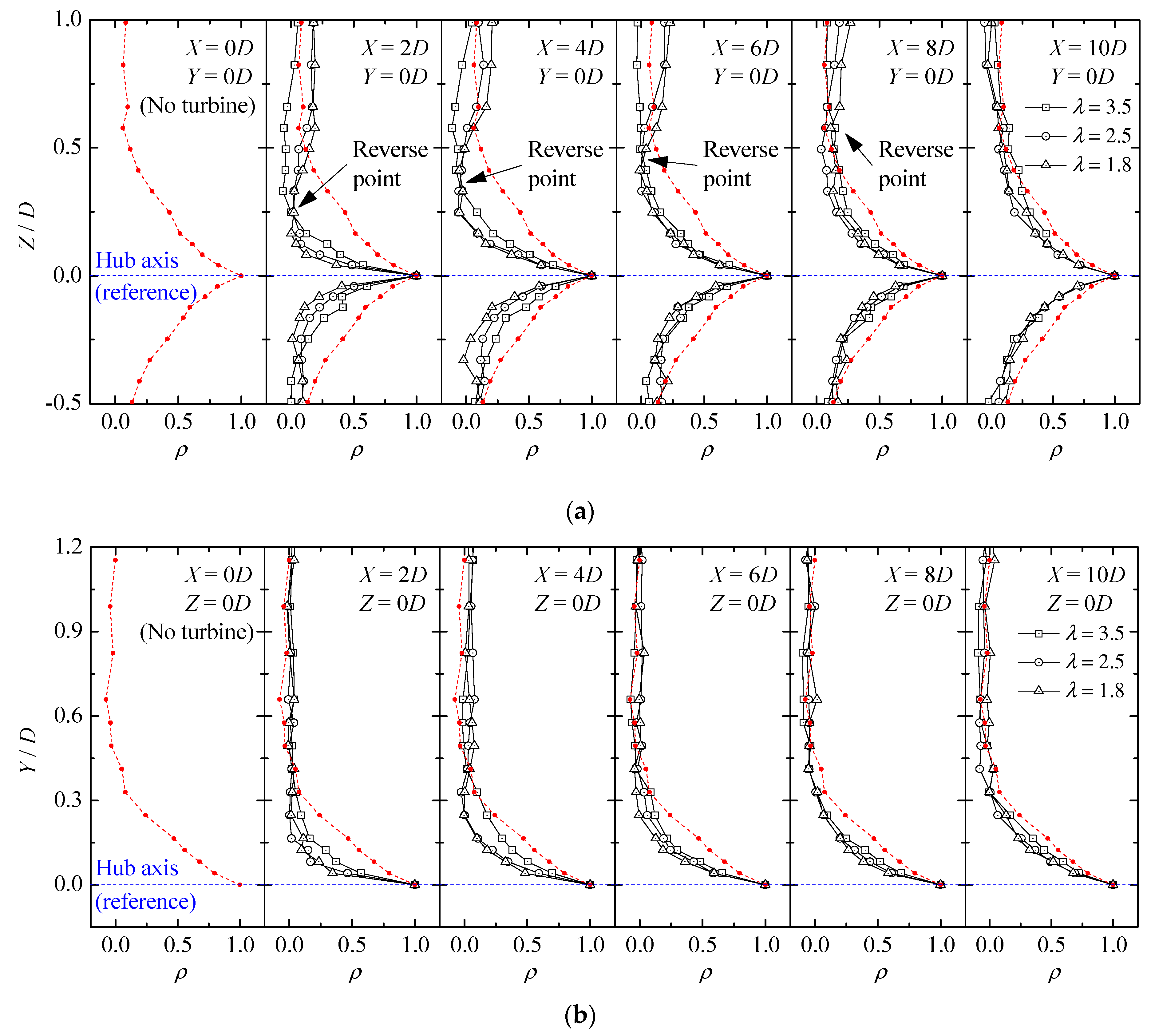
Taking the hub axis as the reference position first (y = 0, z = 0), Figure 6 shows the correlation coefficient between the streamwise velocity at the wake centre and the streamwise velocity at a radial position along y- and z-directions, respectively. Measurements were made at different values of X/D ranging from 0 to 10. It can be seen from Figure 6 that the variations of along the two directions show similar trends. The turbine captures energy from the incoming flow and disturbs it, changing the spatial correlation of velocity fluctuations in the wake flow. The correlation coefficient at X/D = 0 reflects the characteristics of undisturbed incoming flow and this baseline curve is shown in all parts of Figure 6 for comparison.
In the central zone of the blade swept area, the correlation coefficient decreases largely from the free field value at X/D = 0. This may be due to the impedance of the turbine nacelle to the wind flow. The decreased spatial velocity correlation recovered at slightly different rates among the different TSRs, especially when X was not larger than 4D. The faster the rotation, the more the decreased correlation coefficient recovers, and this may be caused by the hub vortex rotating with the turbine and increasing the velocity correlation. With the increase in Z/D, the correlation coefficients of the three cases were close to one another, and the effect from the turbine rotation speed reversed when Z/D was higher than a critical value marked as the reverse point in Figure 6a. This means that at a large radial separation, a faster turbine rotational speed causes a larger decrease in the correlation coefficient. This may be attributed to the stronger impedance of the turbine blades at higher rotational speeds. This critical radial separation to the hub axis moves outwards with the increase in X. More concretely, the separation was observed at Z/D = 0.23 when X was equal to 2D while Z/D = 0.60 when X increased to 8D. The correlation characteristics were still affected to some degrees at X/D = 10. However, it is expected that at a sufficiently far downstream distance from the wind turbine, the wake effect will eventually die down and the correlation coefficients will return to those of the undisturbed incoming flow. In addition, a faster turbine rotational speed leads to stronger tip vortices with more correlated characteristics, but these vortices would diffuse outwards and have less influence on the inner zone of the blade swept area.
For a more direct comparison, the total correlation coefficient representing the spatial correlation of a circular area to its center, i.e., the reference position p, is defined as
where is the correlation coefficient between the reference position and a point related to a very small area around it; is equal to as the blade swept area is selected, as shown in Figure 7. Here, the total correlation coefficient is approximated by the average of the correlation coefficients at a number of measurement points, say, points 1, 2, 3, and 4, along four radial lines (see Figure 7). Velocity fluctuations at points 1, 2, and 3 were measured in the wind tunnel tests and their correlation coefficients to the center are shown in Figure 6, while the value at point 4 was assumed to be same as that at point 2. The approximate total correlation coefficients within the blade swept area at different streamwise locations were computed and are listed in Table 2. It can be seen that the of the undisturbed incoming flow was 0.232 at X/D = 0. After passing through the wind turbine, decreased significantly. The decrease in ranged from 70.8% to 75.6% for = 1.8, 2.5 and 3.5 at X/D = 2. With the recovery of the wake characteristics along the x-direction, increased gradually. However, the decrease in remained a high value at X/D = 10, with an average value of approximately 41.3%.
In the other set of correlation measurements, the reference position p was located at one side location downstream of the blade tip (Y = −0.5D, Z = 0, see Figure 5), while the other position m was placed at different locations along the same horizontal line from one side to the other side of the blade tip. Measurements were made at different values of X/D ranging from 0 to 4 within which the changes in wake characteristics were more significant. As shown in Figure 8, the correlation curves in all cases dropped almost monotonically with the increasing separation between the two points. In the turbine wake, the correlation coefficients became lower than that in the freestream flow, especially at small separation distances. Near the turbine (X/D = 1), it was observed that the faster the turbine rotation, the smaller the correlation coefficient became, as explained above. With the increase in X/D, this phenomenon gradually disappears. Among the three cases, the decreasing range of the correlation coefficient was the maximum for = 3.5, while the recovery for this case was also the fastest. In addition, at the other side of the reference position, small negative correlation coefficients may occur (e.g., X = 3, 4D and Y = 0.1~0.5D). The negative correlation implies that wind velocity fluctuations at the two positions were out of phase, and this may be due to the three-blade geometry and the strong tip vortex when the turbine rotational speed was large enough.
4. Wake Effects on a Downstream HAWT
After understanding the performance and the wake characteristics of a single HAWT, two HAWTs in a tandem arrangement (see Figure 1b) were taken as examples to study how the wake of a turbine affects the performance of another. The two HAWTs had the same parameters, as shown in Section 2.1. The location of the upstream turbine was fixed at x = 0, while the downstream turbine was located at different downstream locations so as to achieve varying separation distance L. Their root pitch angles were named and , respectively. Three root pitch angles, i.e., 7.5°, 15°, and 22.5°, were used in the wind tunnel tests.
was first set equal to . Compared with the output power of a single turbine with the same pitch angle, the percentage change in power generation of both the two turbines are shown in Figure 9 (see solid points connected by dashed lines). Due to the aerodynamic interference between the two turbines in tandem arrangement, their output powers both decreased when compared with a single isolated turbine, especially for the downstream turbine. The aerodynamic interference became weaker with the increase in L/D, so the output powers recovered gradually. No matter how fast the downstream turbine rotates, the effect on the performance of the upstream one is limited, for its output power loss is very small and can almost be ignored when L/D is larger than 2. For the downstream turbine, however, the output power may drop a lot as it is located in the wake of the upstream one. Apparently, this power loss largely depends on . The faster the rotational speed of the upstream turbine is, the smaller the output power of the downstream turbine becomes. For = 7.5°, the output power loss of the downstream turbine exceeded 60% when L/D was 1 or 2, and was still up to about 20% even when L/D increased to 12. With the increasing , the rotational speed of the upstream turbine decreased, so its wake had less adverse effects on the downstream turbine’s performance. For = 22.5°, the range of the output power loss of the downstream turbine decreased to about 10% and remained stable within the range of L/D from 1 to 10. was then changed to the other two values not equal to . The resulting changes in for these two cases are also shown in Figure 9 in the form of an “error” bar. Once was fixed, of the downstream turbine at a given location fluctuated within a small range with the change in its own pitch angle, i.e., .
In summary, the downstream turbine’s performance was mainly determined by the wake characteristics of the upstream one, which were associated with its pitch angle, while adjusting the pitch angle of the downstream wind turbine itself could not help much to mitigate the loss in power generation.
As discussed in Section 3, a turbine captures energy from the incoming flow and the rotating turbine blades generate a turbulent wake behind the turbine with lower wind velocities, smaller correlation, and larger turbulence intensities, as compared to the undisturbed incoming flow. However, the question remains as to how these factors affect the downstream turbine performance, and which one is the major factor governing the downstream turbine performance?
To address this question, the upstream and the downstream turbines with the same root pitch angle of 7.5° were taken as examples, and the percentage changes in power generation () of the downstream turbine at different separation L/D are listed in Table 3. The turbulent wake generated by the upstream wind turbine was mainly described in terms of the mean wind velocity, the turbulence intensity, and the total correlation coefficient. The three parameters were averaged over the blade swept area, and their differences with the corresponding parameters in the undistributed flow were computed and are listed in Table 3 as , , and , respectively. To study their effects separately, the performance of a single wind turbine was tested under the flow conditions simulating the turbulent wake characteristics based on the parameter values in Table 3.
The single turbine was fixed at the same position as that in Section 3, but the inflow condition was changed. To test the effect due to the reduced wind velocities approaching the downstream turbine in the two-turbine situation, uniform incoming flow was simulated in the wind tunnel with wind speed reduced from m/s in the earlier tests. The decrease in wind velocity is given in the third column of in Table 3. The output turbine power was then tested, and the resulting percentage changes are shown by in Table 3. To test the effect of increased turbulence intensities, turbulent incoming flow was simulated in the wind tunnel, which was achieved by adding floor roughness elements in the wind tunnel, as shown in Figure 10. The increase in turbulence intensity is given in the fifth column in Table 3. The output power was tested, and the resulting percentage changes are shown by in Table 3. To analyze the effect of altered spatial velocity correlation, which, however, is difficult to test separately, the corresponding percentage power change was estimated by . In summary, and represent the output power losses directly measured at corresponding mean wind velocities and turbulence intensities, while indirectly represents the effect of the wake correlation.
Table 3 suggests that either a lower wind velocity or a higher turbulence intensity in the incoming flow leads to smaller power generation. For the downstream turbine among two turbines in tandem, the changes in wind velocity and turbulence intensity are brought about by the wake of the upstream turbine. The decrease in power generation in , caused by the lower wind velocity, is obviously larger than that in , caused by the higher turbulence intensity. Higher turbulence intensities are expected to make the rotational speed of the turbine less stable, but this effect on the power generation is relatively small. Compared with the higher turbulence intensity, the reduced mean wind velocity is a much more dominant factor leading to the power loss of the downstream wind turbine. Particularly, the single wind turbine under uniform inflow with the simulated velocity corresponding to the case of = −58% could not even start to rotate, so was given a value of −100%. One possible reason for this phenomenon is that the rotation of a turbine is more sensitive to the flow characteristics near the tip than that near the hub. The wake generated by the upstream turbine is non-uniform, so that the outer ring close to blade tip has higher velocities than the inner ring close to hub. Although and are obtained under the same mean wind speed within the blade swept area, the rotational speed of the turbine in the two-turbine test was higher than the single turbine case due to the non-uniform wake flow, and hence, the decrease in power generation was lower. On the other hand, the phenomenon also indicates that the effects of wake may be beneficial to rotating the turbine, especially at relatively low wind speeds. This viewpoint can also be verified by other cases. As the decrease in power generation due to the and was much greater than that in , there may be some beneficial factors in having the turbine being located in the turbulent wake of an upstream one.
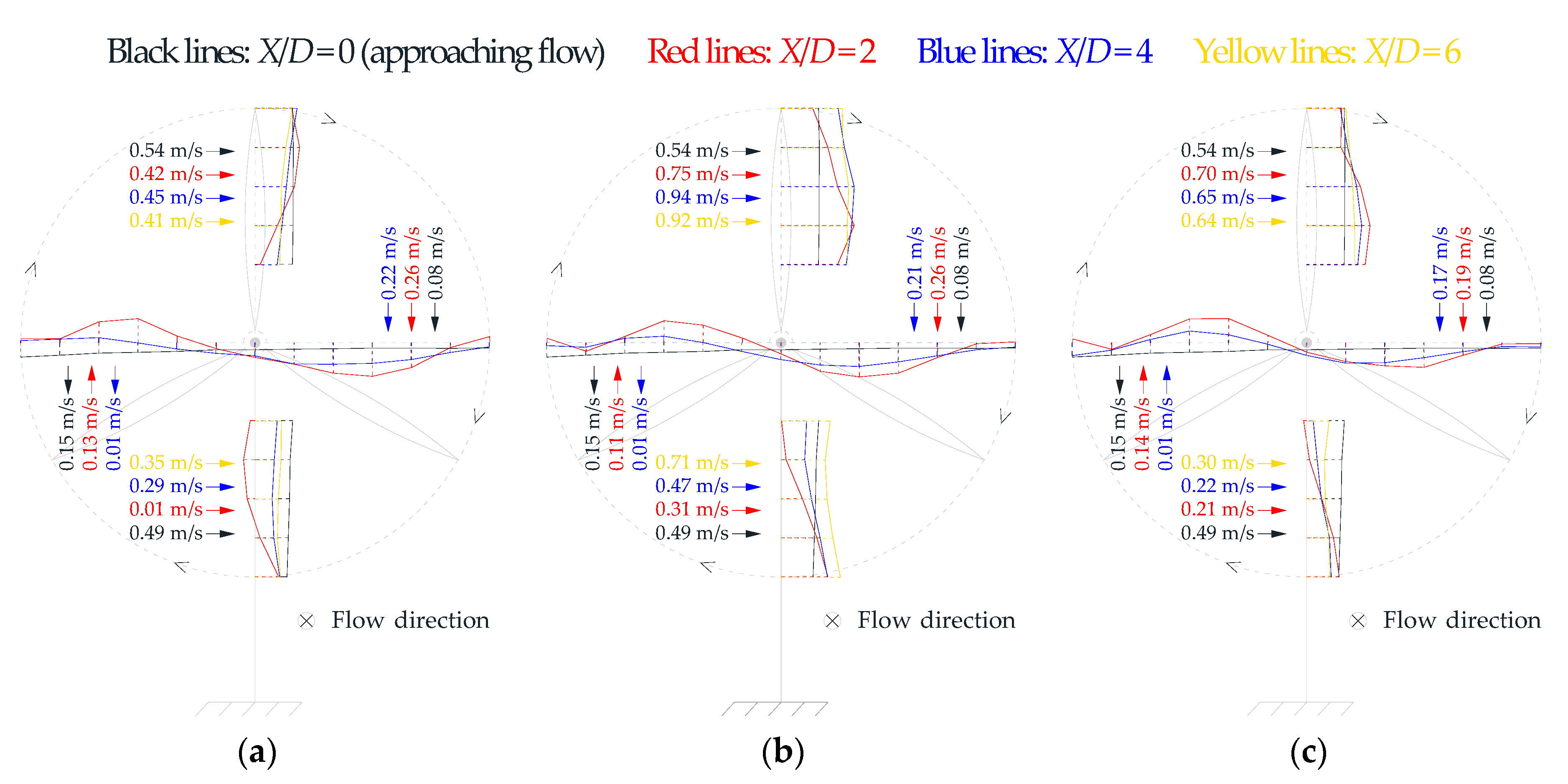
The wake correlation appears to be a beneficial factor governing the performance of the wind turbine. According to the values among , , and , it is estimated that has a positive value. In other words, the change in wake correlation may be favorable to the performance of the downstream turbine. The previous section mainly focuses on the change in which represents the correlation of the streamwise velocities within the blade swept area to its center. This correlation decreases obviously in the wake, but relatively, the decrease in may imply the increase in correlation at other directions such as the tangential and radial velocities. As discussed in Section 3, owing to the three-blade geometry and the strong tip vortices, anti-correlation could be observed between the two opposite sides of the blade swept area, which acts to decrease . To better illustrate this, the wake characteristics in the single turbine with different (see Section 3) were focused again, and the time-averaged mean tangential velocities along the radial lines from the hub axis to the top, right, bottom, and left of the blade swept area are shown in Figure 11. The values of the mean tangential velocity averaged over the four paths and the corresponding directions are also given in the figure.
The approaching flow at X/D = 0 in the wind tunnel did not go perfectly in the axial direction and there were inevitably some velocity values in the other two directions. As measured with the cobra probe, the values of the mean tangential velocities averaged over the top path and the bottom path were 0.54 m/s and 0.49 m/s with the same direction, i.e., rightward. Similarly, the values of the mean tangential velocities averaged over the left path and the right path were 0.15 m/s and 0.08 m/s with the same direction as well, i.e., downward. In this situation, if a turbine is placed, the incoming flow will have opposite effects on a blade when it passes through the top and bottom positions, or the left and right positions.
When the incoming flow is disturbed by an upstream wind turbine, however, the tangential velocities along the four paths obviously change. Due to the fluid rotation in the turbine wake, the tangential velocities at one side, such as the top and the right paths, could be increased from the undisturbed case, while the values at the other side, such as the bottom and the left paths, could be decreased. About the hub axis, the velocity differs between the top and the bottom paths to form a clockwise effect, and so do the right and the left paths. This difference was affected by and decreased with the increase in X/D. Thus, the rotation of the downstream wind turbine will be enhanced due to the sustained clockwise effect that the aerodynamic forces acting on the three blades are now more in phase. In summary, the decrease in was accompanied with the increase in correlation of the tangential velocities within the blade area, which was favorable to the downstream turbine’s performance. However, the effect from this wake correlation was expected to be much weaker than that due to the reduced wind velocities. The values of in Table 3 are far from realistic.
5. Conclusions
In this study, the wake characteristics of a three-blade horizontal axis wind turbine model at different TSRs were measured and analyzed. The effect of the turbine wake on the performance of a downstream turbine was also studied using wind tunnel tests. The main conclusions of this study are summarized as follows:
- (1)
- At a fixed velocity of incoming flow, the rotational speed of the wind turbine decreased with the increase in blade pitch angle, especially when the pitch angle was between 7.5° and 22.5°. This led to a reduction of the power coefficient. With the increase in velocity of incoming flow, the rotational speed of the wind turbine increased stably but the power coefficient first increased to a peak value and then decreased again.
- (2)
- After passing through the wind turbine, the velocity of incoming flow decreased but the turbulence intensity increased significantly. These wake effects were strong within the blade swept area and decreased progressively from the hub center to the blade tip. A small pitch angle provided smaller disturbance to the flow, but the blades turned faster, leading to larger changes in the wind velocity and turbulence intensity due to the more frequent passage of the turbine blades. Compared with the region above the hub axis, the wake characteristics below the hub axis were more difficult to recover due to the presence of the ground surface and disruption of the flow from the supporting pole.
- (3)
- The turbine captured energy from the incoming flow and disturbed it, changing the correlation of the wake flow. Around the hub axis, the wake correlation decreased significantly from the freestream case, but this effect could be slightly weakened by the rotation of the turbine. The faster the rotational speed of the turbine was, the more this decreased correlation coefficient recovered. Overall, the decreased correlation within the blade swept area gradually recovered to the freestream values increased at increasing downstream locations. Moreover, an anti-correlated region can be observed at the two lateral sides of the turbine blade swept area.
- (4)
- Due to the aerodynamic interference between the two turbines in the tandem arrangement, their output powers both decreased when compared with a single isolated turbine, especially for the downstream one. The interference became weaker with the increase in their separation distance, so the output powers recovered gradually. As the performance of the downstream turbine was mainly determined by the wake of the upstream one, the output power of the downstream turbine decreased with the increase in rotational speed of the upstream turbine, but was less related to its own pitch angle. In the wake of the upstream turbine, the reduced mean wind velocity was the most dominant factor in determining the loss of power generation of the downstream turbine. Although higher turbulence intensities make the rotational speed of the turbine less stable, the unfavourable effect was limited. The wake correlation was another important factor governing the performance of the downstream turbine. The decrease in the correlation of the streamwise velocity within the blade swept area was accompanied with the increased correlation of the tangential velocity, which may be favorable to the downstream turbine performance.
- (5)
- This paper mainly focused on the wake characteristics of the wind turbine whose performance was evaluated based on its power generation only, while the changes in thrust force and power quality should be further investigated. Meanwhile, the Reynolds number in the present wind tunnel experiments was much smaller than those in most commercial wind turbine installations. Although previous studies have shown that the primary wake characteristics behind a turbine can be reproduced at relatively low Reynolds numbers, the Reynolds number effect on the results should be further studied by numerical simulations or field experiments.
Author Contributions
Conceptualization, K.M.L.; methodology, H.T., K.-M.L. and Y.L.; investigation, H.T., K.-M.S. and Y.L.; formal analysis, H.T. and K.-M.S.; writing—original draft, H.T.; writing—review and editing, H.T., K.-M.L., K.-M.S. and Y.L.
Funding
This research received no external funding.
Conflicts of Interest
The authors declare no conflict of interest.
References
- Xie, W.; Zeng, P.; Lei, L.P. Wind tunnel experiments for innovative pitch regulated blade of horizontal axis wind turbine. Energy 2015, 91, 1070–1080. [Google Scholar] [CrossRef]
- Xie, W.; Zeng, P.; Lei, L.P. Wind tunnel testing and improved blade element momentum method for umbrella-type rotor of horizontal axis wind turbine. Energy 2017, 119, 334–350. [Google Scholar] [CrossRef]
- Sutrisno; Iswahyudi, S.; Wibowo, S.B. Dimensional analysis of power prediction of a real-scale wind turbine based on wind-tunnel torque measurement of small-scaled models. Energies 2018, 11, 2374. [Google Scholar] [CrossRef]
- Lee, M.H.; Shiah, Y.C.; Bai, C.J. Experiments and numerical simulations of the rotor-blade performance for a small-scale horizontal axis wind turbine. J. Wind Eng. Ind. Aerodyn. 2016, 146, 17–29. [Google Scholar] [CrossRef]
- Lin, Y.T.; Chiu, P.H.; Huang, C.C. An experimental and numerical investigation on the power performance of 150 kW horizontal axis wind turbine. Renew. Energy 2017, 113, 85–93. [Google Scholar] [CrossRef]
- Li, Q.A.; Maeda, T.; Kamada, Y.; Mori, N. Investigation of wake effects on a horizontal axis wind turbine in field experiments (Part I: Horizontal axis direction). Energy 2017, 134, 482–492. [Google Scholar] [CrossRef]
- Howard, K.B.; Guala, M. Upwind preview to a horizontal axis wind turbine: A wind tunnel and field-scale study. Wind Energy 2016, 19, 1371–1389. [Google Scholar] [CrossRef]
- Chamorro, L.P.; Arndt, R.E.A.; Sotiropoulos, F. Reynolds number dependence of turbulence statistics in the wake of wind turbines. Wind Energy 2012, 15, 733–742. [Google Scholar] [CrossRef]
- Park, Y.M.; Chang, B.H.; Cho, T.H. Numerical simulation of wind turbine scale effects by using CFD. In Proceedings of the 45th AIAA Aerospace Sciences Meeting and Exhibit, Reno, NV, USA, 8–11 January 2007. [Google Scholar]
- Ge, M.W.; Tian, D.; Deng, Y. Reynolds number effect on the optimization of a wind turbine blade for maximum aerodynamic efficiency. J. Energy Eng. 2016, 142, 04014056. [Google Scholar] [CrossRef]
- Li, X.X.; Yang, K.; Zhang, L.; Bai, J.Y. Experimental study of Reynolds number effects on performance of thick CAS wind turbine airfoils. J. Renew. Sustain. Energy 2017, 9, 063309. [Google Scholar] [CrossRef]
- Tarhan, C.; Yilmaz, İ. Numerical and experimental investigations of 14 different small wind turbine airfoils for 3 different reynolds number conditions. Wind Struct. 2019, 28, 141–153. [Google Scholar]
- Parker, C.M.; Leftwich, M.C. The effect of tip speed ratio on a vertical axis wind turbine at high Reynolds numbers. Exp. Fluids 2016, 57, 74. [Google Scholar] [CrossRef]
- Zanforlin, S.; Deluca, S. Effects of the Reynolds number and the tip losses on the optimal aspect ratio of straight-bladed vertical axis wind turbines. Energy 2018, 148, 179–195. [Google Scholar] [CrossRef]
- Leung, D.Y.C.; Yang, Y. Wind energy development and its environmental impact: A review. Renew. Sustain. Energy Rev. 2012, 16, 1031–1039. [Google Scholar] [CrossRef]
- Barthelmie, R.J.; Hansen, K.; Frandsen, S.T.; Rathmann, O.; Schepers, J.G.; Schlez, W.; Phillips, J.; Rados, K.; Zervos, A.; Politis, E.S.; et al. Modelling and measuring flow and wind turbine wakes in large wind farms offshore. Wind Energy 2009, 12, 431–444. [Google Scholar] [CrossRef]
- Porté-Agel, F.; Wu, Y.T.; Chen, C.H. A numerical study of the effects of wind direction on turbine wakes and power losses in a large wind farm. Energies 2013, 6, 5297–5313. [Google Scholar] [CrossRef]
- Medici, D.; Alfredsson, P.H. Measurements on a wind turbine wake: 3D effects and bluff body vortex shedding. Wind Energy 2006, 9, 219–236. [Google Scholar] [CrossRef]
- Hu, H.; Yang, Z.F.; Sarkar, P. Dynamic wind loads and wake characteristics of a wind turbine model in an atmospheric boundary layer wind. Exp. Fluids 2012, 52, 1277–1294. [Google Scholar] [CrossRef]
- Zhang, W.; Markfort, C.D.; Porté-Agel, F. Near-wake flow structure downwind of a wind turbine in a turbulent boundary layer. Exp. Fluids 2012, 52, 1219–1235. [Google Scholar] [CrossRef]
- Bastankhah, M.; Porté-Agel, F. Experimental and theoretical study of wind turbine wakes in yawed conditions. J. Fluid Mech. 2016, 806, 506–541. [Google Scholar] [CrossRef]
- Qian, Y.R.; Zhang, Z.Y.; Wang, T.G. Comparative study of the aerodynamic performance of the new MEXICO rotor under yaw conditions. Energies 2018, 11, 833. [Google Scholar] [CrossRef]
- Chu, C.R.; Chiang, P.H. Turbulence effects on the wake flow and power production of a horizontal-axis wind turbine. J. Wind Eng. Ind. Aerodyn. 2014, 124, 82–89. [Google Scholar] [CrossRef]
- Adaramola, M.S.; Krogstad, P.-Å. Experimental investigation of wake effects on wind turbine performance. Renew. Energy 2011, 36, 2078–2086. [Google Scholar] [CrossRef]
- Bastankhah, M.; Porté-Agel, F. Wind tunnel study of the wind turbine interaction with a boundary-layer flow: Upwind region, turbine performance, and wake region. Phys. Fluids 2017, 29, 1–24. [Google Scholar] [CrossRef]
- Talavera, M.; Shu, F.J. Experimental study of turbulence intensity influence on wind turbine performance and wake recovery in a low-speed wind tunnel. Renew. Energy 2017, 109, 363–371. [Google Scholar] [CrossRef]
- Theunissen, R.; Scarano, F.; Riethmuller, M.L. Spatially adaptive PIV interrogation based on data ensemble. Exp. Fluids 2010, 48, 875–887. [Google Scholar] [CrossRef]
- Willert, C.E.; Gharib, M. Digital particle image velocimetry. Exp. Fluids 1991, 10, 181–193. [Google Scholar] [CrossRef]
Figure 1.
Wind tunnel tests: (a) a single wind turbine; (b) two wind turbines in operation.

Figure 2.
Wind turbine performance. (a) relationship between RPM and ; (b) relationship between RPM and
Figure 2.
Wind turbine performance. (a) relationship between RPM and ; (b) relationship between RPM and
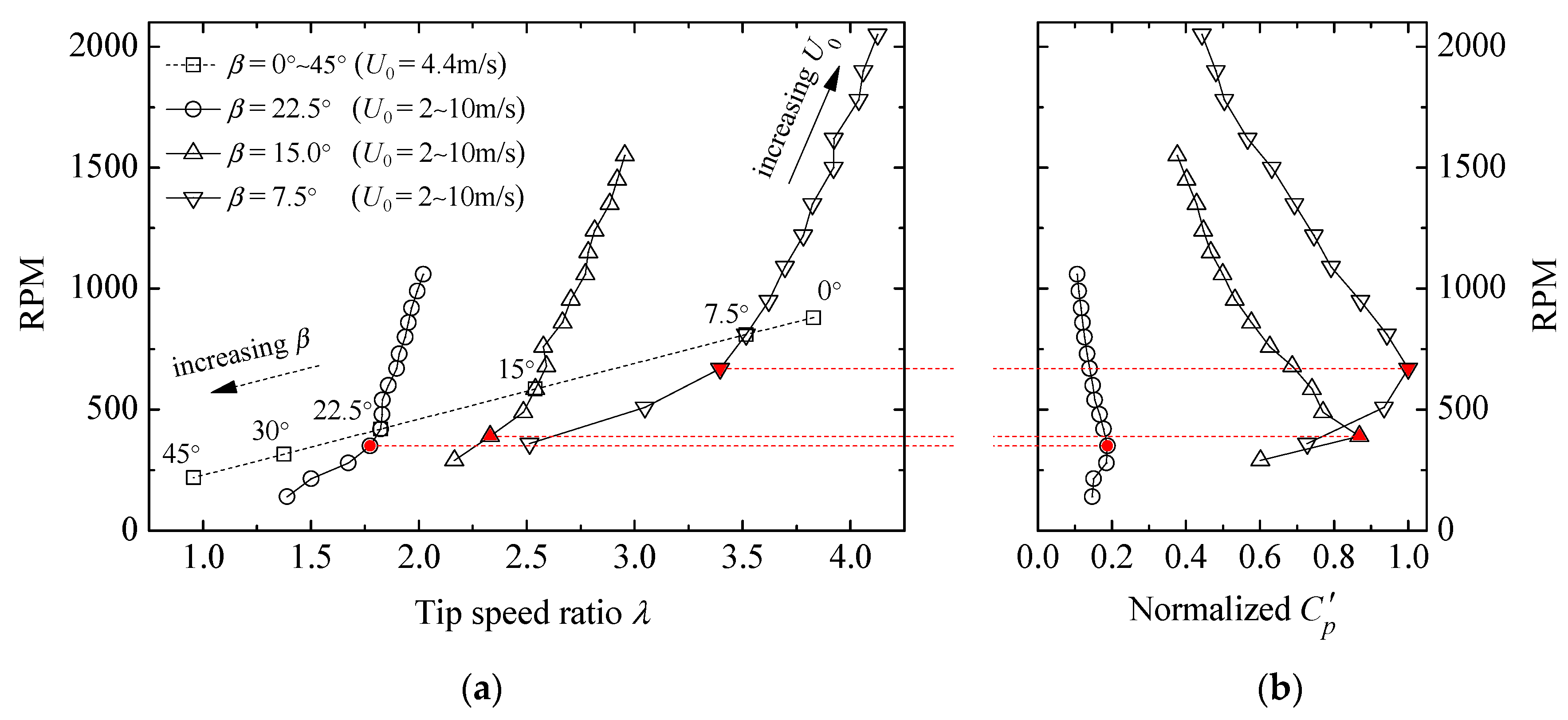
Figure 3.
Wake characteristics of the turbine with larger TSRs: (a) streamwise velocity ratio; (b) streamwise turbulence intensity.
Figure 3.
Wake characteristics of the turbine with larger TSRs: (a) streamwise velocity ratio; (b) streamwise turbulence intensity.
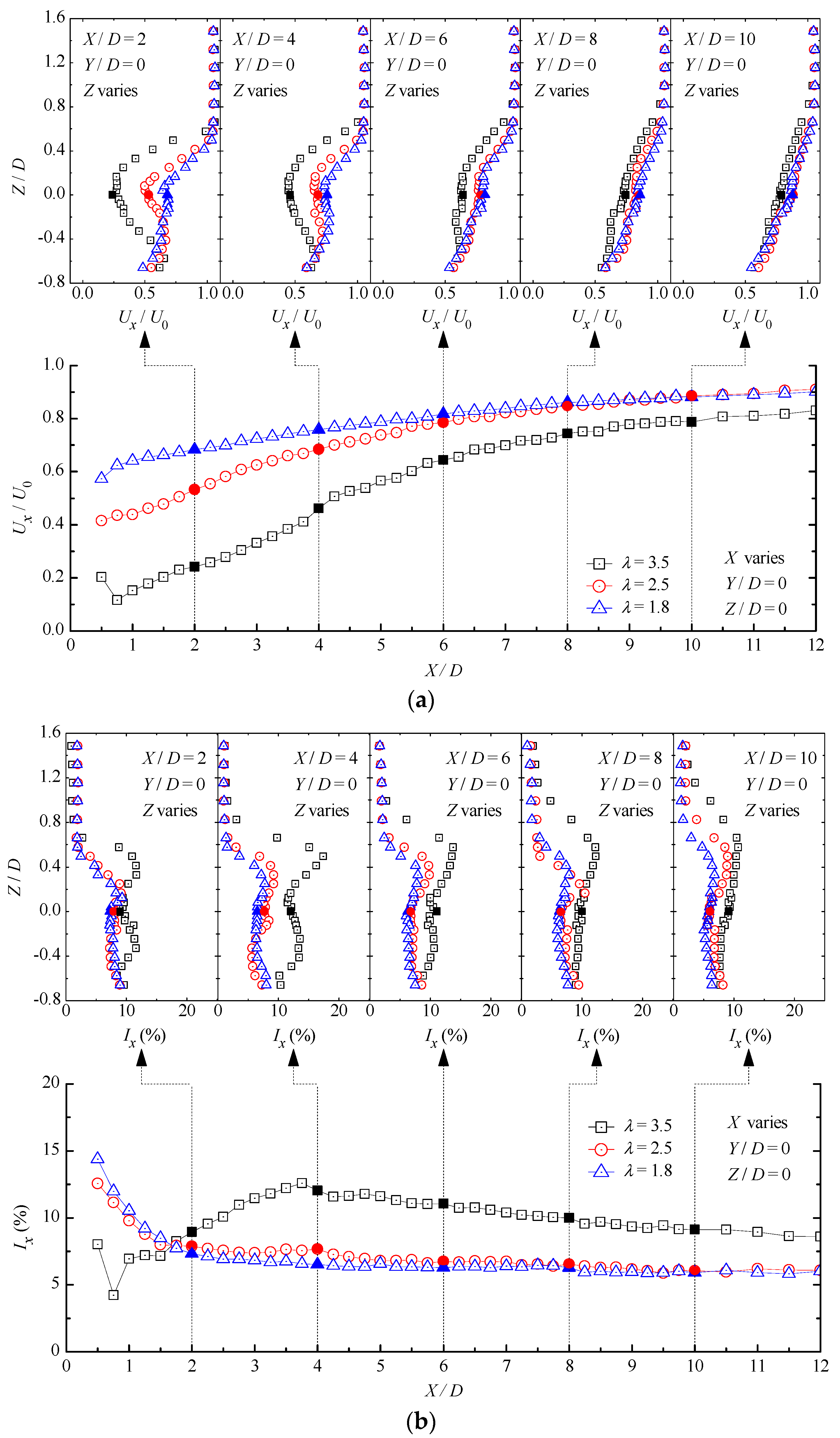
Figure 4.
Wake fields of the turbine with a smaller TSR: (a) streamwise velocity ratio; (b) streamwise turbulence intensity; (c) vertical velocity ratio; (d) normalized turbulent kinetic energy.
Figure 4.
Wake fields of the turbine with a smaller TSR: (a) streamwise velocity ratio; (b) streamwise turbulence intensity; (c) vertical velocity ratio; (d) normalized turbulent kinetic energy.
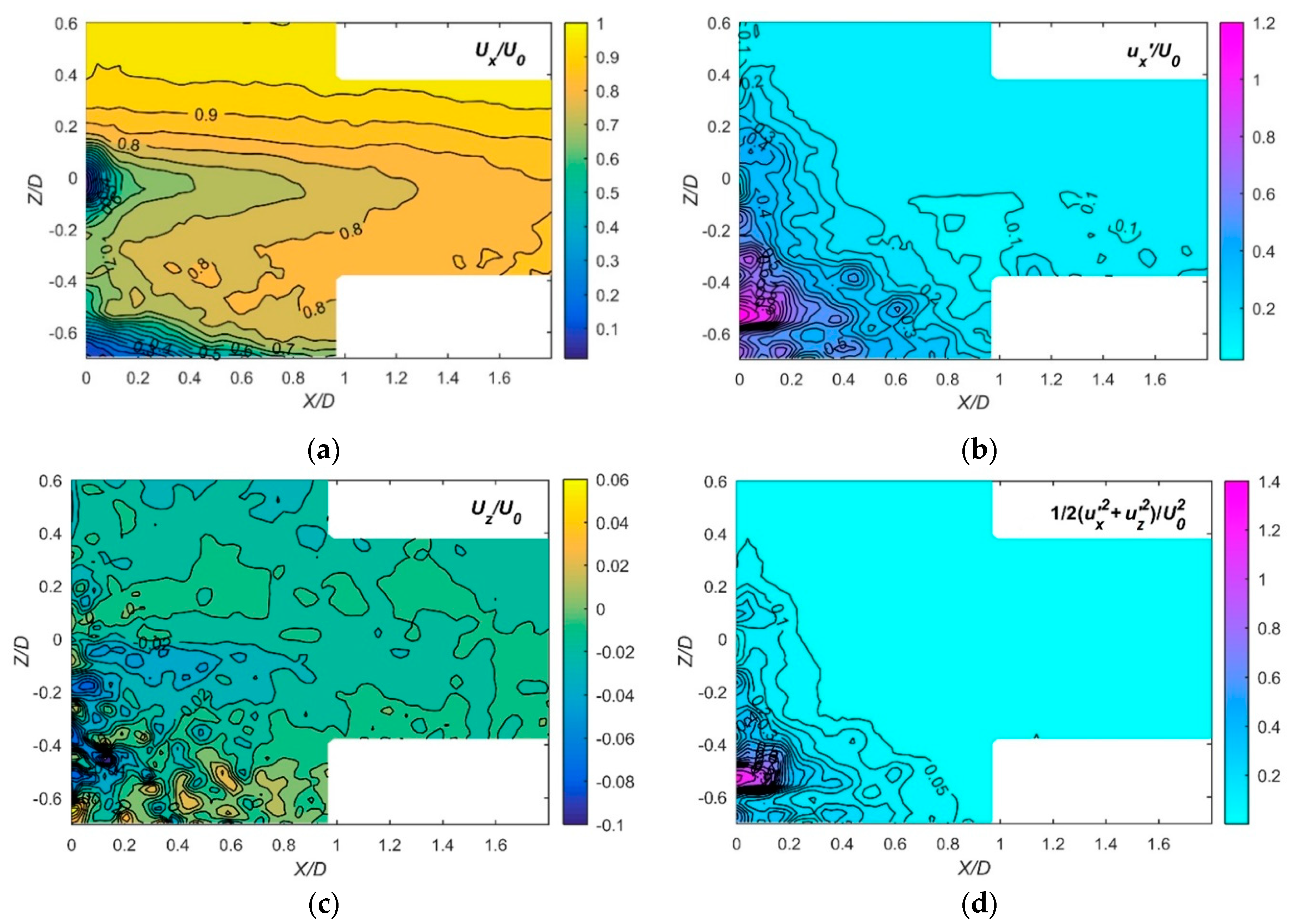
Figure 5.
Schematic diagram for reference positions.
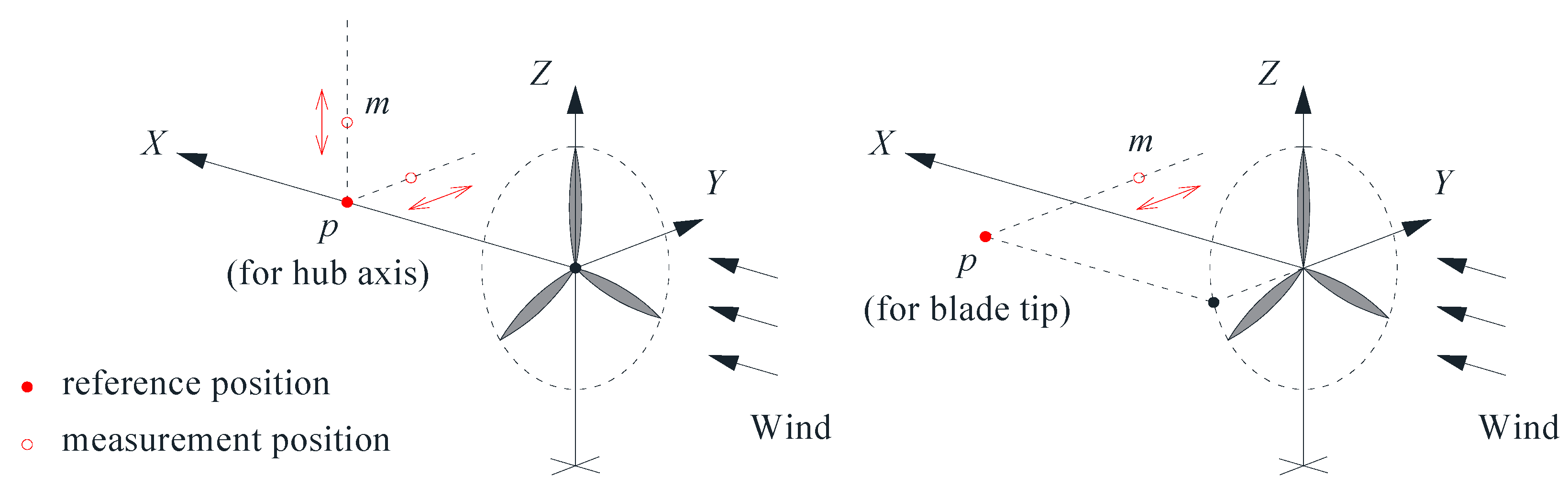
Figure 6.
Correlation coefficients for hub axis: (a) along the z-direction; (b) along the y-direction.
Figure 6.
Correlation coefficients for hub axis: (a) along the z-direction; (b) along the y-direction.

Figure 7.
Schematic diagram for definition of the total correlation coefficient.

Figure 8.
Correlation coefficients for blade tip along the y-direction.
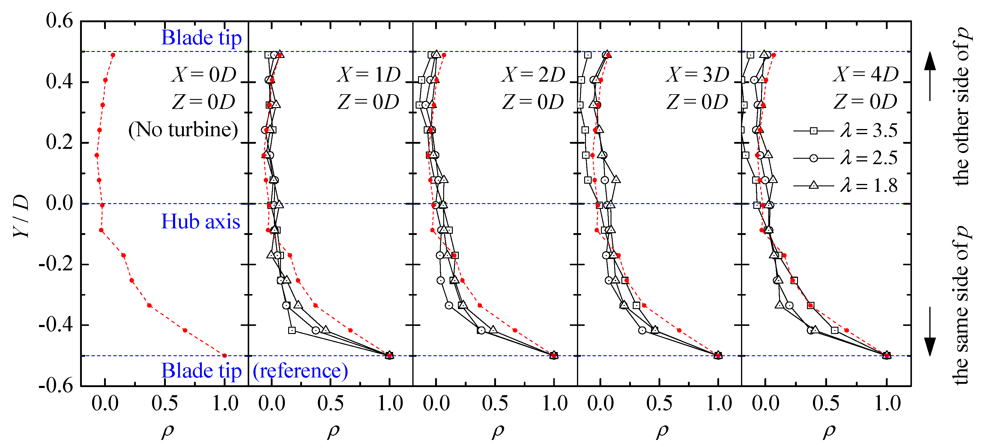
Figure 9.
Variation ranges of output power at different gap spacing: (a) the upstream wind turbine; (b) the downstream wind turbine.
Figure 9.
Variation ranges of output power at different gap spacing: (a) the upstream wind turbine; (b) the downstream wind turbine.
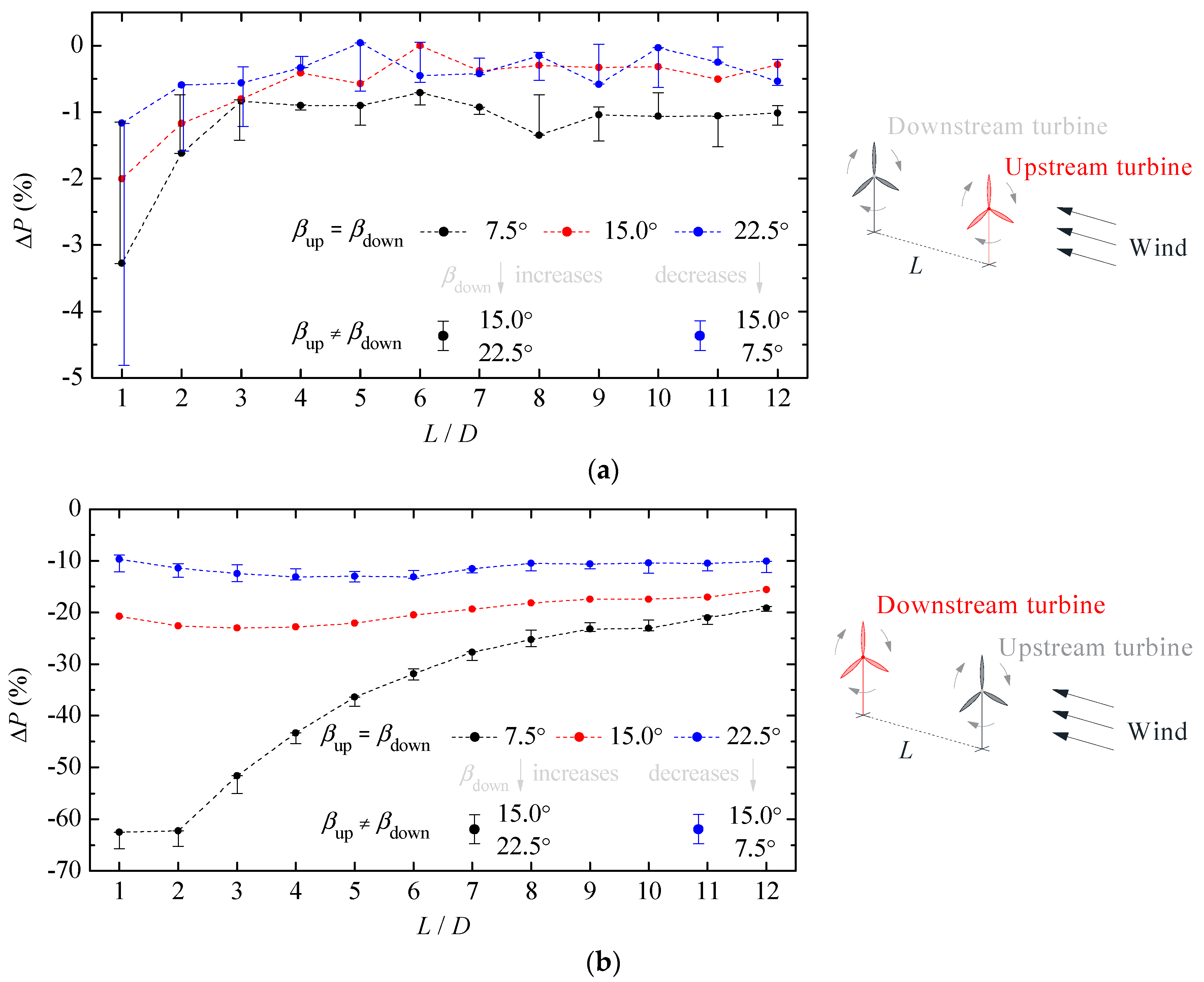
Figure 10.
Different incoming flow conditions: (a) uniform; (b) turbulent; (c) more turbulent.
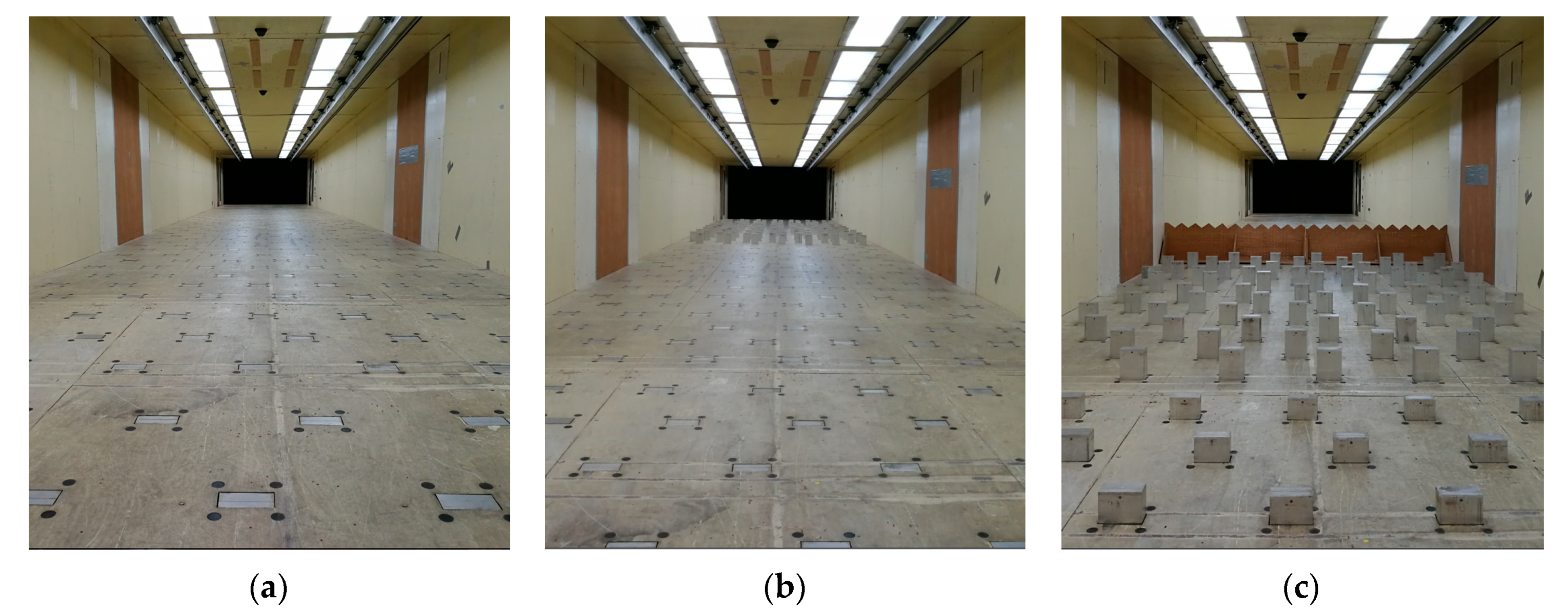
Figure 11.
Mean tangential velocities in the turbine wake: (a) = 7.5°; (b) = 15°; (c) = 22.5°.

Table 1.
Relationship between the tip speed ration (TSR) and root pitch angle.
| Items | Root Pitch Angle β (°) | |||||
|---|---|---|---|---|---|---|
| 0 | 7.5 | 15 | 22.5 | 30 | 45 | |
| RPM | 880 | 810 | 585 | 420 | 316 | 220 |
| TSR | 3.8 | 3.5 | 2.5 | 1.8 | 1.4 | 1.0 |
Table 2.
Total correlation coefficients within the blade swept area
| Total Correlation Coefficient | ||||||
|---|---|---|---|---|---|---|
| X = 0D | X = 2D | X = 4D | X = 6D | X = 8D | X = 10D | |
| 3.5 | 0.232 (no turbine) | 0.0676 | 0.1159 | 0.1051 | 0.1438 | 0.1598 |
| 2.5 | 0.0567 | 0.0625 | 0.0987 | 0.1042 | 0.1049 | |
| 1.8 | 0.0600 | 0.0515 | 0.0751 | 0.1254 | 0.1442 | |
| Average | 0.0614 | 0.0766 | 0.0930 | 0.1245 | 0.1363 | |
Table 3.
Variation ranges of output power at different flow conditions.
| Two HAWTs: | A Single HAWT: | ||||||
|---|---|---|---|---|---|---|---|
| Tested | Estimated | ||||||
| 2 | −62.2 | −58 | −100.0 | +29 | - | −71 | - |
| 4 | −43.3 | −43 | −86.8 | +25 | - | −50 | - |
| 6 | −31.9 | −31 | −69.2 | +17 | −1.4 | −55 | +38.7 |
| 8 | −25.3 | −24 | −54.5 | +13 | - | −38 | - |
| 10 | −23.1 | −19 | −43.6 | +11 | −4.9 | −31 | +25.4 |
© 2019 by the authors. Licensee MDPI, Basel, Switzerland. This article is an open access article distributed under the terms and conditions of the Creative Commons Attribution (CC BY) license (http://creativecommons.org/licenses/by/4.0/).
Share and Cite
MDPI and ACS Style
Tang, H.; Lam, K.-M.; Shum, K.-M.; Li, Y. Wake Effect of a Horizontal Axis Wind Turbine on the Performance of a Downstream Turbine. Energies 2019, 12, 2395. https://doi.org/10.3390/en12122395
AMA Style
Tang H, Lam K-M, Shum K-M, Li Y. Wake Effect of a Horizontal Axis Wind Turbine on the Performance of a Downstream Turbine. Energies. 2019; 12(12):2395. https://doi.org/10.3390/en12122395
Chicago/Turabian StyleTang, Haojun, Kit-Ming Lam, Kei-Man Shum, and Yongle Li. 2019. "Wake Effect of a Horizontal Axis Wind Turbine on the Performance of a Downstream Turbine" Energies 12, no. 12: 2395. https://doi.org/10.3390/en12122395
Note that from the first issue of 2016, this journal uses article numbers instead of page numbers. See further details here.