Static Voltage Sharing Design of a Sextuple-Break 363 kV Vacuum Circuit Breaker †


1
State Key Laboratory of Power Transmission Equipment & System Security and New Technology, School of Electrical Engineering, Chongqing University, Chongqing 400044, China
2
Electric Power Research Institute of Ningxia Electric Power Company of State Grid Corporation of China, Yinchuan 750001, China
3
Wuhan NARI Limited Company of State Grid Electric Power Research Institute, Wuhan 430074, China
*
Author to whom correspondence should be addressed.
†
This paper is an extended version of our paper published in 2018 IEEE International Conference on High Voltage Engineering and Application (ICHVE 2018), Athens, Greece, 10–13 September 2018; pp. 1–4.
Energies 2019, 12(13), 2512; https://doi.org/10.3390/en12132512
Submission received: 22 May 2019
/
Revised: 25 June 2019
/
Accepted: 26 June 2019
/
Published: 29 June 2019
(This article belongs to the Special Issue Selected Papers from 2018 IEEE International Conference on High Voltage Engineering (ICHVE 2018))
Abstract
:A balanced voltage distribution for each break is required for normal operation of a multi-break vacuum circuit breaker (VCB) This paper presented a novel 363 kV/5000 A/63 kA sextuple-break VCB with a series-parallel structure. To determine the static voltage distribution of each break, a 3D finite element method (FEM) model was established to calculate the voltage distribution and the electric field of each break at the fully open state. Our results showed that the applied voltage was unevenly distributed at each break, and that the first break shared the most voltage, about 86.3%. The maximum electric field of the first break was 18.9 kV/mm, which contributed to the reduction of the breaking capacity. The distributed and stray capacitance parameters of the proposed structure were calculated based on the FEM model. According to the distributed capacitance parameters, the equivalent circuit simulation model of the static voltage distribution of this 363 kV VCB was established in PSCAD. Subsequently, the influence of the grading capacitor on the voltage distribution of each break was investigated, and the best value of the grading capacitors for the 363 kV sextuple-break VCB was confirmed to be 10 nF. Finally, the breaking tests of a single-phase unit was conducted both in a minor loop and a major loop. The 363 kV VCB prototype broke both the 63 kA and the 80 kA short circuit currents successfully, which confirmed the validity of the voltage sharing design.
1. Introduction
Modern power systems have a high requirement for switching appliances, which are essential for the safe and reliable operation of power systems. As an important part of electrical switchgear, the vacuum switch plays an important role in controlling and protecting electrical power systems [1]. Vacuum interrupters have the advantages of environmental friendliness, fine extinction capability, and long lifespan [2]. Vacuum circuit breakers (VCBs) are widely applied in 40.5 kV and lower voltage power systems, while for 126 kV and higher voltage power systems SF6 circuit breakers are mainly used. However, modern power systems have larger loads, which have higher requirements of power quality and safety. Hence, short circuit currents should be interrupted instantly to reduce losses [3]. To date, the commonly used SF6 circuit breakers in 330 kV and 500 kV AC power systems have a long remove fault time of approximately 50 ms [4]. During this period, the fault current reaches its peak several times [5]. According to the dielectric strength, SF6 behaves better than VCBs; hence, VCBs have higher dielectric strength restoration after the current is turned to zero, in comparison with other types of circuit breakers. Nowadays, VCBs with controlled switching technology, such as permanent magnetic mechanisms, spring type mechanisms, and electromagnetic repulsion mechanisms, are able to achieve fast interruption during a rising slope within 2–7 ms [6,7,8,9]. However, single-break VCBs are limited to 126 kV due to the saturation effect of the vacuum gap and the overheating problem [10].
There are two ways to develop high-voltage VCBs: higher-voltage single-break VCBs and multi-break VCBs. Due to the saturation characteristic of the vacuum gap, single VCBs are limited to 126 kV. Conversely, multi-break VCBs, which are several vacuum interrupters connected in series, can eliminate the saturation effect and increase the breaking capacity [10]. Hence, the multi-break VCB has drawn more attention [11,12,13,14,15]. The total interruption time of VCBs with an ultra-fast electromagnetic repulsion mechanism and a fault current detection system can be reduced to 10–20 ms [13]. Based on this technology, several features of double- and triple-break VCBs have been investigated, including the open velocity, voltage distribution, and synchronization of each VCB; additionally, a breaking test has been conducted on prototypes [13,16,17]. Vertical series connected structures of double- and triple-break VCBs have been investigated with the purpose of analyzing their static voltage distribution. According to these results, the stray capacitance and post-arc characteristic of uneven voltage distribution limit the breaker capacity and the grading capacitors can improve the balance of voltage distribution and breaking capacity.
However, multi-break VCBs are still limited to under 126 kV. Compared with 126 kV VCBs, higher-voltage VCBs are quite different in structure due to their insulation requirements. Therefore, to extend normal VCBs to 363 kV power systems, two key points should be taken into consideration: (i) the uneven voltage distribution of each break and (ii) the synchronized switching of each break. The voltage distribution of each break can be improved by installing a grading capacitor at each break in parallel to balance the voltage distribution equally [18,19]. As for synchronized switching, a phase-controlled algorithm is always used to detect the fault current changing rate to determine the open time for each break, which ensures the synchronization of the multiple breaks. Furthermore, stray capacitances of multi-break VCBs are mainly decided by the number of breaks, topology, structure, and dimensions. Therefore, for a new 363 kV multi-break VCB, it is necessary to investigate the voltage distribution and stray capacitance in order to design a suitable grading capacitor.
This paper is an extension of our previous work published in ICHVE2018 [20]. Our goal was to determine the value of the grading capacitor for a novel 363 kV sextuple-break VCB taking into account its gas-insulated scheme and series-parallel layout. In order to obtain the static voltage distribution and distributed capacitances of the VCB, a three-dimensional finite element model based on the actual dimension parameters of the single-phase unit was established. An equivalent capacitance network model in PSCAD was also set up to analyze the influence of the grading capacitor on the voltage distribution of each break. Finally, a breaking test was conducted to verify the performance of the grading capacitors.
2. Structure of the 363 kV Circuit Breaker
This section gives the topological structure, dimensions, and parameters of the proposed sextuple-break 363 kV VCB.
2.1. Determination of the Number of Breaks
The vacuum gap is able to withstand a strong electric field and voltage level, and its breakdown voltage is directly proportional to its open distance. However, the large vacuum gap exhibits a saturation phenomenon. The voltage level of VCBs varies greatly, ranging from 3.6 to 72 kV. For a 363 kV VCB, in an open state it must be able to sustain the nominal voltage and the surge voltage. If low-voltage VCBs such as 12 kV VCBs are adopted, many breaks are needed, which would lead to the need for more complex structures and greater costs. The most widely used commercial VCBs are 40.5 kV VCBs, and these are considered to be the best choice. However, the rated current of a 40.5 kV VCB is 2500 A, so a parallel structure of two branches is needed for a rated current of 5000 A and a rated breaking current of 63 kA. To allow for sufficient breaking capacity and sufficient margin, sextuple-break with two branches of parallel structure was adopted. Consequently, the physical structure of the proposed 363 kV VCB was formed by 1240.5 kV VCBs in a series-parallel structure with grading capacitors and inductors (see Figure 1). Series inductors were used to share the current for each phase and grading capacitors were used to share the voltage for each break.
2.2. Structure Design
When designing the structure of a high-voltage multi-break VCB, insulation, size, maintenance, and total cost are the key factors for consideration. A gas-insulated high-voltage apparatus, such as a gas-insulated switchgear, has the advantage of being compact and maintenance-free with a long mechanical life, while other outdoor apparatuses requires tall structures to satisfy their requirement for insulation against ground. Hence, the gas-insulated apparatus was the best choice. The prototype design and connection structure are shown in Figure 2. The VCBs were totally enclosed in the aluminum tank filled with 0.4 MPa SF6 with inlet busbar and outlet busbar. The 40.5 kV VCBs were also connected to terminals and other VCBs by a concentric cylindrical busbar. The dimensions and parameters of the 363 kV VCB and 40.5 kV VCB are shown in Table 1 and Table 2, respectively.
The vacuum interrupter worked with a fast short circuit current prediction algorithm and a phase control system. The moving contact was driven by an ultrafast electromagnetic repulsion mechanism, so the opening time (500 μs) and opening velocity (up to 5 m/s) could be achieved [6,15]. It adopted a fiber-controlled system to synchronize the VCBs. The open dispersibility (i.e., the time delay of the operation of all VCBs) of these VCBs was shorter than 0.1 ms, and the closed dispersibility was shorter than 0.2 ms. Thus, combined with the above components, a quick current interruption within a short arcing time (3 ms) was achieved. Compared to typical high-voltage circuit breakers 30-60 ms, the total interruption time was reduced to 10–20 ms.
3. Finite Element Method (FEM) Model and Voltage Distribution Calculation
As the 363 kV sextuple-break VCB has a complex structure, analytical methods cannot be used to calculate its voltage distribution. As a consequence, taking into account its symmetry, an FEM model of the single unit was established, and a numerical calculation was performed. In establishing the FEM model, some components were simplified as follows: (1) the end shield, bellows, and contacts were simplified to a metal cylinder; (2) the control system, actuator, disc spring, screw holes, and bolts were removed. The entire opening distance was 20 mm. In the FEM model, the relative permittivity of the insulators was set at 4.95, SF6 at 1.002, and epoxy at 4. The applied voltage was 300 kV on the surface of the static rod of the first break and its connected busbar. The outside tank and the moving rod of the last break and its connected busbar were grounded. All the main shields of the vacuum interrupters were set to floating potential. The voltage freedom degrees of other components were coupled using COMSOL software. Tetrahedral mesh was adopted to deal with the irregular geometry. The total mesh elements, as shown in Figure 3, were 39,442,046. The voltage distribution profile and electric field distribution profile are shown in Figure 4.
According to the calculation results, the voltage distribution was exceedingly uneven due to the stray capacitance. The first break shared most of the total applied voltage, reaching 259 kV and accounting for 86.3% of the voltage, while the sixth break shared only 0.0153 kV. The maximum electric field of the first break was 18.5 kV/mm, which easily gave rise to arc reigniting and reduced the interrupting capacity of the VCB. Table 3 shows the voltage of each break.
4. Grading Capacitor Design
When designing the grading capacitor, we needed to know the distributed capacitance and stray capacitance of the 363 kV VCB, which can be regarded as a multi-conductor system considering the influence of the grounded tank. Under AC voltage, the voltage distribution of a multi-conductor system is determined by the self-capacitance and mutual capacitance of these conductors.
The commercial COMSOL software can easily obtain the distributed capacitance and extract a capacitance matrix by defining the conductors successively. As shown in Figure 5, all of the 13 conductors were defined, where the incoming busbar, the upper terminal of the first break, and the static contact were defined as conductor 1; the main shield, which is the floating potential, of the first VCB as conductor 2; the lower terminal of the first break, lower busbar, and the lower terminal of the second break as conductor 3; and so forth, and the exterior tank was grounded. Among the conductors, conductor 13 was composed of the last connecting terminal, last busbar, and outside tank. The capacitances between the moving contact and the static contact, and the capacitance between the conductor and the tank made a greater difference. Therefore, other stray capacitances between the conductors that were at a great distance from each other, such as the capacitance between the main shields of different VCBs, were ignored.
According to the calculated capacitance matrix, the stray capacitances to the earth were greater than the capacitance of the break of the VCB, which makes the voltage of each break unequal, indicating the need for a voltage sharing design. A grading capacitor was an effective and low-cost measure to balance the voltage of each break. To analyze the influence of the grading capacitor, the equivalent circuit model can be used. Figure 6a illustrates the equivalent capacitance network and the simulation model with a grading capacitor in PSCAD of the 363 kV VCB, where C1 was the capacitance between the moving contact and the static contact of the first break, and C10 was the capacitance between conductor 1 and the tank. Cg was the grading capacitor. The capacitance between the main shield and nearby conductors, which was very small, was attributed to the capacitance nearby to simplify the equivalent capacitor network under the criterion that the voltage of each break equals the results of the FEM simulation. Finally, parameters for the equivalent circuit simulation model were as follows: C1 = C2 = C3 = C4 = C5 = C6 = 14.7 pF; C20 = C40 = C60 = 80 pF; C30 = C50 = 76 pF.
By assigning a different value to the grading capacitors, the change in the voltage of the first break along with the grading capacitors is shown in Figure 7. Table 4 shows the voltage variation of the first break at different grading capacitor values. The values of the grading capacitors were set in the range of 700 to 12,000 pF. The authors of [13] indicated that grading capacitors of 1000 pF can meet the opening requirements of a 126 kV triple-break VCB. However, for the 363 kV VCB, the first break shared 23.3% of the applied voltage when the grading capacitor was 1000 pF. When the grading capacitor was 6000 pF, the voltage distribution ratio of the six breaks from one to six was 18.4%, 17.5%, 16.3%, 15.9%, 15.5%, and 15.1%, respectively. The voltage distribution ratio of the first break was 3.2% higher than the sixth. Furthermore, when the grading capacitor exceeded 10,000 pF, the rate of improvement slowed down.
The voltage unbalance coefficient (K) is defined as:
where is the voltage of the ith break and is the average voltage of each break.
When K > 1, the voltage was unevenly distributed. When the grading capacitance equaled 6000 pF, K = 1.1; when the grading capacitance equaled 10,000 pF, K = 1.07. In addition, the accepted standard for selecting grading capacitors in China is that the voltage unbalanced coefficient should be below 1.1. However, according to China’s national standard GB 4787-2010 [21], the preferred minimum for a grading capacitor is 1000 pF in consideration of the function of reducing the steepness of the transient recovery voltage (TRV) [17]. Other researchers have adopted 400 pF grading capacitors for double-break VCBs [19] and 1000 pF grading capacitors for 126 kV triple-break VCBs [17]. Greater grading capacitor values lead to a decrease in the breaking capacitor value because of the post arc current. Hence, the value of grading capacitors for the sextuple-break 363 kV VCB was set at 10 nF in this study.
5. Breaking Test of the 363 kV VCB
The synthetic test circuit, as recommended by IEC standards, was used to impose the appropriate stresses on the test circuit breaker (CB) during the breaking test, as shown in Figure 8. These circuits were essential to verify the short circuit current making and breaking capabilities of the 363 kV VCB. The supply circuit capacity of the synthetic test circuit was 480 kV/80 kA. The grading capacitors were connected in parallel with the VCB. The test was carried out on a single phase only, and in type T100s and T100a both for 63 kA (minor loop) and 80 kA (major loop). The first-pole-to-clear factor was 1.3.
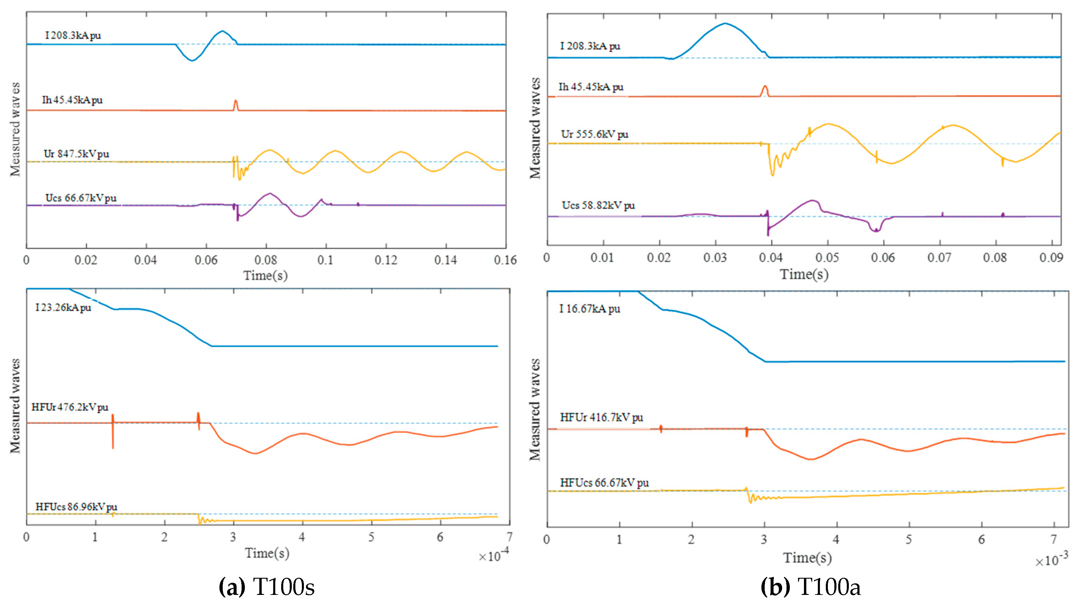
The prototype of the 363 kV sextuple-break VCB interrupted the short circuit current (symmetrical and asymmetrical) successfully in a high-voltage apparatus quality supervision and inspection test center as a preliminary research test. The key information is summarized in Table 5, and all recorded waveforms of the breaking current and the TRV are shown in Figure 9 and Figure 10. In Figure 9 and Figure 10, I is the test current, Ih is the small zero crossing current of synthetic test circuit, Ur is the total transient recovery voltage, Ucs is the voltage of the current source, HFUcs is the high-frequency voltage of the current source, and HFUr is the high-frequency transient recovery voltage. The recovery voltage is less than 258 kV and the TRV peak is less than 544 kV, which indicates that the grading capacitors of 10 nF can meet the requirement of the voltage sharing design and breaking capacity.
6. Summary and Conclusions
This paper presented a novel sextuple-break 363 kV VCB that can remove a short circuit fault in an extremely short time. An FEM model based on actual dimensions was established to calculate the static voltage distribution and the stray capacitance to determine its grading capacitor design. At the fully open state, the voltage distribution of the proposed structure was uneven, and the first break undertook 259 kV, accounting for 86.3% of the total applied voltage. Subsequently, an equivalent capacitor network model was set up in PSCAD based on the parameters from the FEM model. Along with the increase of the grading capacitor value, the voltage of the first break decreased rapidly, and the voltage distribution of each break became more even. The best value of the grading capacitor was 10 nF, and its corresponding voltage unbalance coefficient was 1.07. Finally, T100s and T100a breaking tests were conducted at the short current of 63 kA and 80 kA both in a minor loop and a major loop. The prototype 363 kV VCB passed the test at the maximum TRV of 544 kV, which demonstrated that the performance of grading capacitors can satisfy the requirements of the voltage sharing design. In our future work, we will focus on the sextuple-break 363 kV VCB’s dynamic opening mechanism to gain a deeper insight into the dynamic voltage distribution of the sextuple-break 363 kV VCB and put forward better grading measures.
Author Contributions
Conception, modelling, writing, editing: X.Y; supervision: F.Y.; funding acquisition: S.A., Y.H., Y.F.; experiment: W.D.; review and editing: X.Y, X.L.
Funding
This research was founded by Science and Technology Project of State Grid Corporation of China (grant 5229DK160005), National Key R&D Program of China (grant 2017YFB0902703) Chongqing Postdoctoral Fund Special Grant Project (grant Xm2017195).
Conflicts of Interest
The authors declare no conflict of interest.
References
- Chen, H.; Liu, X.; Li, L.; Liu, Y.; Zhang, Y.; Huang, Y. Analysis of Dynamic Arc Parameters for Vacuum Circuit Breaker Under Short-Circuit Current Breaking. IEEE Trans. Appl. Supercond. 2019, 29, 1–5. [Google Scholar] [CrossRef]
- Yao, X.; Wang, J.; Geng, Y.; Yan, J.; Liu, Z.; Yao, J.; Liu, P. Development and type test of a single-break 126-kV/40-kA–2500-A vacuum circuit breaker. IEEE Trans. Power Deliv. 2016, 31, 182–190. [Google Scholar] [CrossRef]
- Liu, H.; Wang, Z.; Yang, J.; Li, B.; Ren, A. Circuit Breaker Rate-of-Rise Recovery Voltage in Ultra-High Voltage Lines with Hybrid Reactive Power Compensation. Energies 2018, 11, 100. [Google Scholar] [CrossRef]
- Franck, C.M. HVDC circuit breakers: A review identifying future research needs. IEEE Trans. Power Deliv. 2011, 26, 998–1007. [Google Scholar] [CrossRef]
- Jankowski, P.; Mindykowski, J. Study on the Hazard Limitation of Hybrid Circuit Breaker Actuator Operation. Energies 2018, 11, 416. [Google Scholar] [CrossRef]
- Zhang, B.; Ren, L.; Ding, J.G.; Wang, J.; Liu, Z.; Geng, Y.; Yanabu, S. A Relationship between Minimum Arcing Interrupting Capability and Opening Velocity of Vacuum Interrupters in Short-circuit Current Interruption. IEEE Trans. Power Deliv. 2018, 33, 2822–2828. [Google Scholar] [CrossRef]
- Tan, Y.; Kun, Y.; Xiang, B.; Wang, J.; Liu, Z.; Geng, Y.; Yanabu, S. Repulsion mechanism applied in resistive-type superconducting fault current limiter. IEEE Trans. Appl. Supercond. 2016, 26, 1–9. [Google Scholar] [CrossRef]
- He, Z.; Wang, S. Design of the electromagnetic repulsion mechanism and the low-inductive coil used in the resistive-type superconducting fault current limiter. IEEE Trans. Appl. Supercond. 2014, 24, 1–4. [Google Scholar] [CrossRef]
- Hou, C.; Yu, X.; Cao, Y.; Lai, C.; Cao, Y. Prediction of synchronous closing time of permanent magnetic actuator for vacuum circuit breaker based on PSO-BP. IEEE Trans. Dielectr. Electr. Insul. 2017, 24, 3321–3326. [Google Scholar] [CrossRef]
- Homma, M.; Sakaki, M.; Kaneko, E.; Yanabu, S. History of vacuum circuit breakers and recent developments in Japan. IEEE Trans. Dielectr. Electr. Insul. 2006, 13, 85–92. [Google Scholar] [CrossRef]
- Cheng, X.; Chen, S.; Ge, G.; Wang, H.; Wu, Q. Investigating on Synergy Effect of Series-Connected Vacuum Arcs in Multi-break VCBs. In Proceedings of the 2018 28th International Symposium on Discharges and Electrical Insulation in Vacuum (ISDEIV), Greifswald, Germany, 23–28 September 2018; Volume 2, pp. 671–674. [Google Scholar]
- Ge, G.; Liao, M.; Duan, X.; Cheng, X.; Zhao, Y.; Liu, Z.; Zou, J. Experimental investigation into the synergy of vacuum circuit breaker with double-break. IEEE Trans. Plasma Sci. 2016, 44, 79–84. [Google Scholar] [CrossRef]
- Huang, D.; Wu, G.; Ruan, J. Study on Static and Dynamic Voltage Distribution Characteristics and Voltage Sharing Design of a 126-kV Modular Triple-Break Vacuum Circuit Breaker. IEEE Trans. Plasma Sci. 2015, 43, 2694–2702. [Google Scholar] [CrossRef]
- Horn, A.; Lindmayer, M. Investigations on the series connection of two switching gaps in one tube in vacuum. IEEE Trans. Plasma Sci. 2005, 33, 1594–1599. [Google Scholar] [CrossRef]
- Zhang, B.; Tan, Y.; Ren, L.; Wang, J.; Geng, Y.; Liu, Z.; Yanabu, S. Interruption Capability of a Fast Vacuum Circuit Breaker with a Short Arcing Time. In Proceedings of the XXVIIth International Symposium on Discharges and Electrical Insulation in Vacuum, Suzhou, China, 18–23 September 2016; pp. 1–4. [Google Scholar]
- Huang, D.; Shu, S.; Ruan, J. Transient recovery voltage distribution ratio and voltage sharing measure of double-and triple-break vacuum circuit breakers. IEEE Trans. Compon. Packag. Manuf. Technol. 2016, 6, 545–552. [Google Scholar] [CrossRef]
- Ge, G.; Cheng, X.; Liao, M.; Huang, Z.; Zou, J. Mechanism of dynamic voltage distribution in series-connected vacuum interrupters. IEEE Trans. Plasma Sci. 2018, 46, 3083–3089. [Google Scholar] [CrossRef]
- Fugel, T.; Koenig, D. Influence of grading capacitors on the breaking performance of a 24-kV vacuum breaker series design. IEEE Trans. Dielectr. Electr. Insul. 2003, 10, 569–575. [Google Scholar] [CrossRef]
- Sugita, M.; Igarashi, T.; Kasuya, H.; Okabe, S.; Matsui, Y.; van Lanen, E.; Yanabu, S. Relationship between the voltage distribution ratio and the post arc current in double-break vacuum circuit breakers. IEEE Trans. Plasma Sci. 2009, 37, 1438–1445. [Google Scholar] [CrossRef]
- Shaogui, A.; Xiao, Y.; Yongning, H.; Fan, Y.; Yiping, F.; Xing, L. Voltage Distribution Design of a Novel 363 kV Vacuum Circuit Breaker. In Proceedings of the 2018 IEEE International Conference on High Voltage Engineering and Application (ICHVE), ATHENS, Greece, 10–13 September 2018; pp. 1–4. [Google Scholar]
- Grading Capacitors for High-Voltage Alternating Current Circuit Breakers. Available online: https://infostore.saiglobal.com/preview/is/en/2014/i.s.en62146-1-2014%2Ba1-2016.pdf?sku=1723996 (accessed on 21 May 2019).
Figure 1.
Topology of a 363 kV sextuple-break vacuum circuit breaker (VCB). Notes: QF means VCB; C means grading capacitor.
Figure 1.
Topology of a 363 kV sextuple-break vacuum circuit breaker (VCB). Notes: QF means VCB; C means grading capacitor.
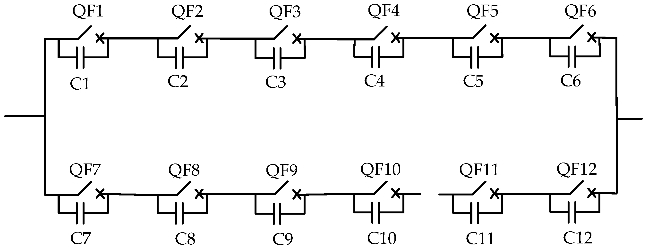
Figure 2.
Single phase structure of the 363 kV VCB.
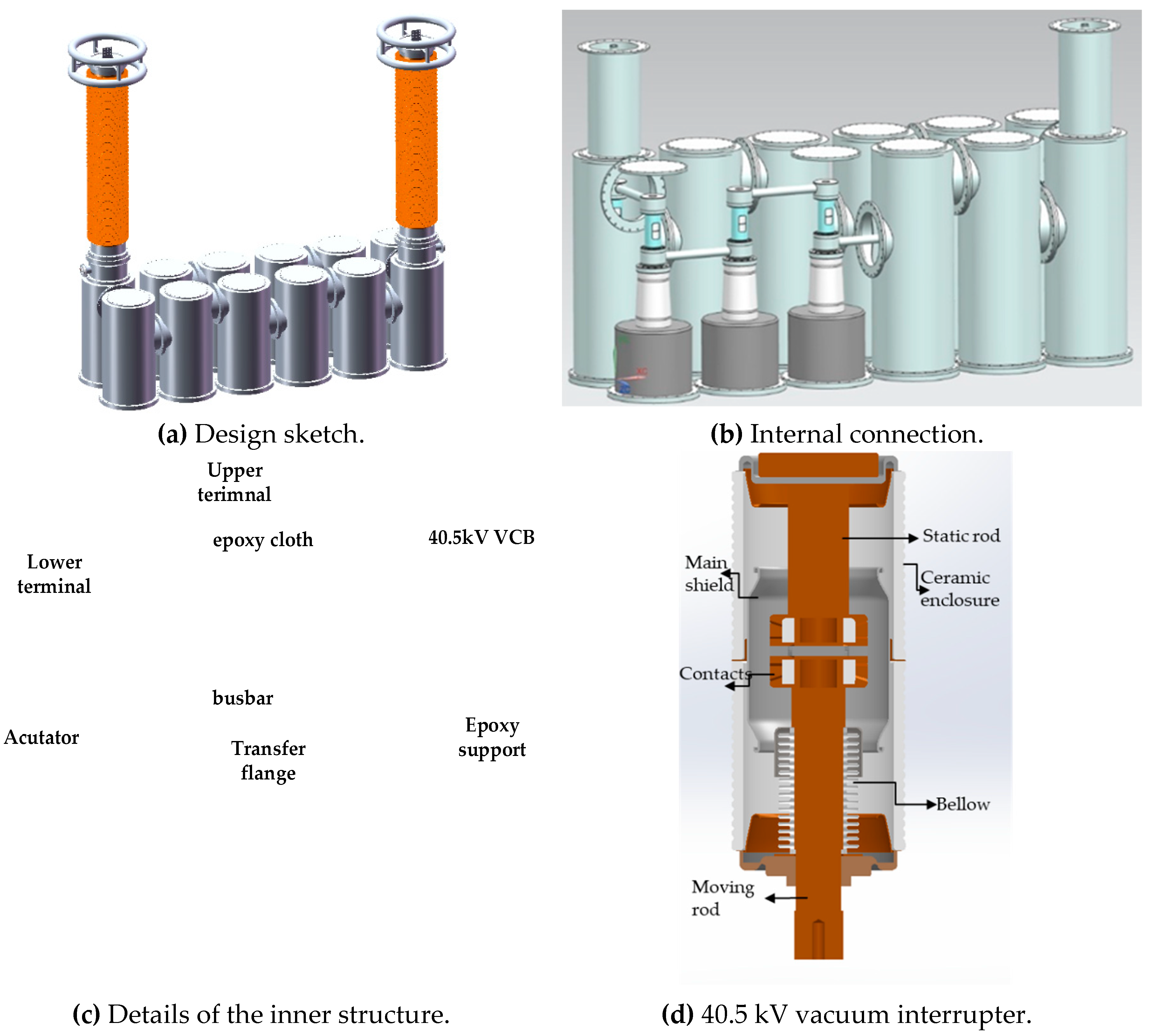
Figure 3.
The mesh of the simulation model.
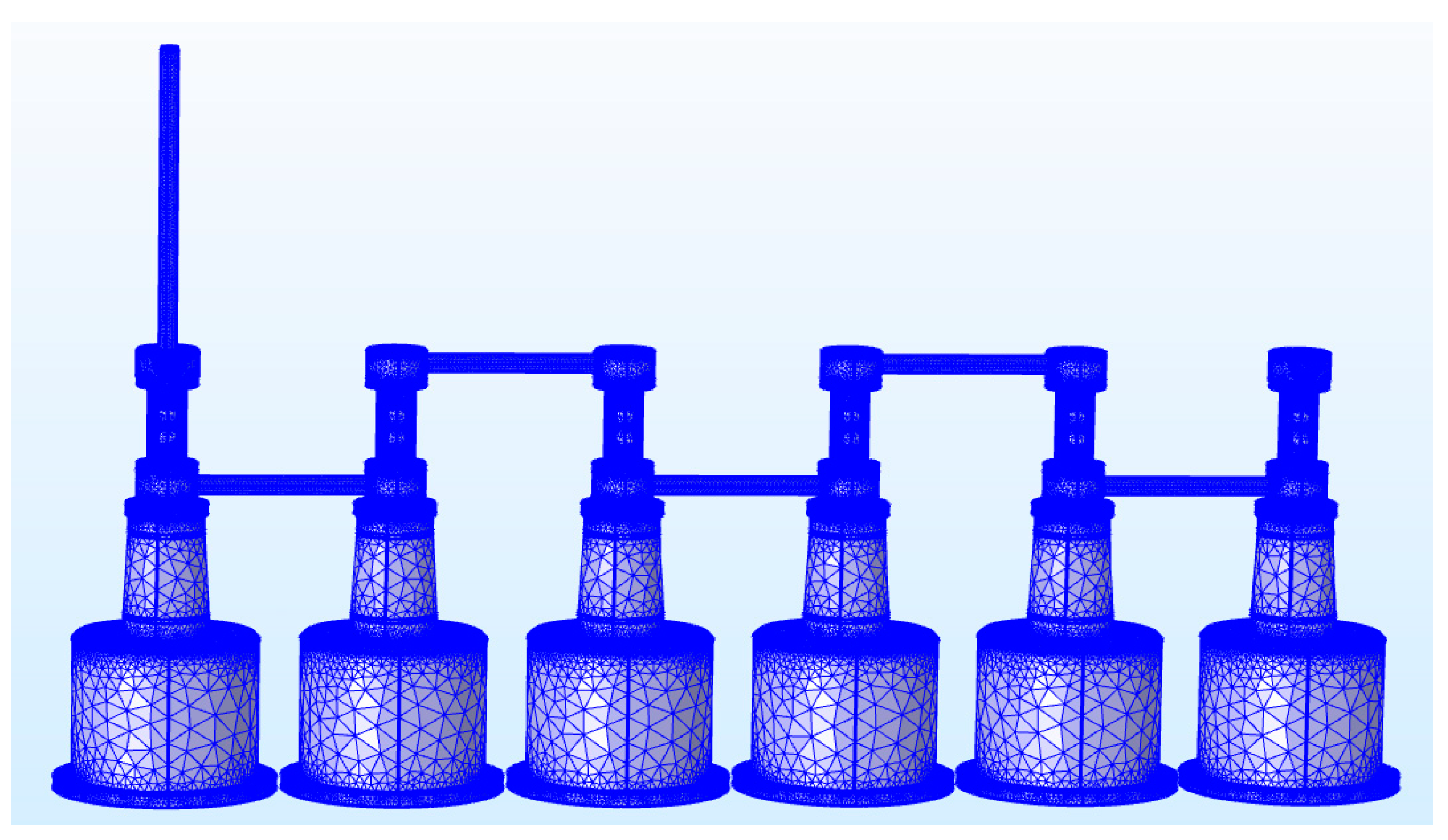
Figure 4.
The static voltage and electric field distribution of the 363 kV VCB.
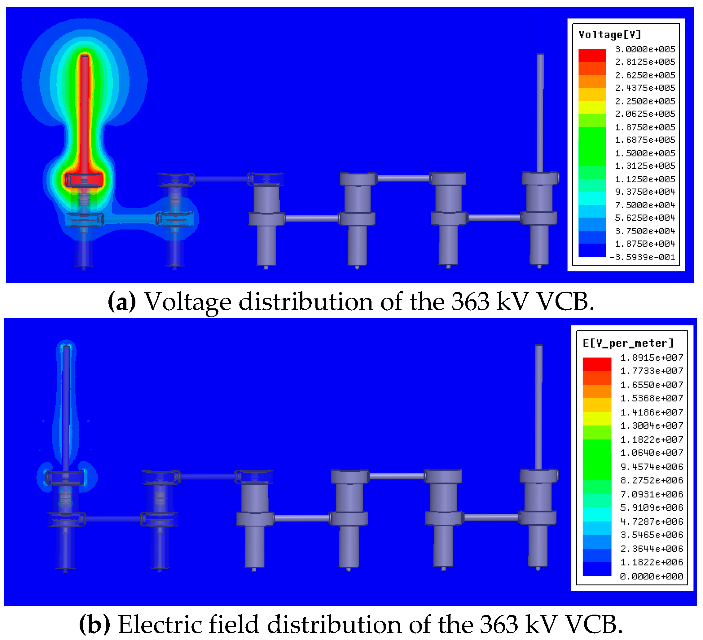
Figure 5.
The conductor definitions.

Figure 6.
The equivalent circuit model of the 363 kV VCB with a grading capacitor.

Figure 7.
Influence of grading capacitors for the 363 kV VCB.
Figure 8.
Breaking test circuit for the 363 kV VCB.G, generator; GB, generator breaker; MS, make switch; MB, master breaker; L, reactor; PT, power transformer; R, resistor; C, capacitor; To, test object; R, arc prolonging circuit; V, voltage measurement; GP, gap; I, current measurement; AB, auxiliary breaker.
Figure 9.
Test waveforms of the synthetic breaking test at 63 kA.
Figure 10.
Test waveforms of the synthetic breaking test at 80 kA.


Table 1.
Dimension of the 363 kV VCB.
| Parameter Name | Value |
|---|---|
| Tank radius | 410 mm |
| Tank height | 2047 mm |
| Busbar external radius | 80 mm |
| Upper and lower terminal radius | 156 mm |
| Transfer flange radius | 245 mm |
Table 2.
Parameters of the 40.5 kV VCB.
| Part Name | Size |
|---|---|
| Moving contact | Radius = 25 mm, length = 190 mm |
| Static contact | Radius = 25 mm, length = 105 mm |
| Contact | Radius = 40 mm, thickness = 30 mm, round radius = 4 mm |
| Ceramic envelope | Radius = 35.5 mm, thickness = 8.5 mm |
| Ceramic envelope | External radius = 240 mm, internal radius = 200 mm, height = 378 mm |
Table 3.
Voltage sharing of each break.
| Break | Voltage | Voltage Distribution Ratio (%) |
|---|---|---|
| V1 | 256 kV | 86.3% |
| V2 | 35.18 kV | 11.73% |
| V3 | 5.03 kV | 1.68% |
| V4 | 0.684 kV | 0.23% |
| V5 | 0.0982 kV | 0.032% |
| V6 | 0.0153 kV | 0.00% |
Note: V1 to V6 denote the first to sixth breaks.
Table 4.
Voltage of the first break at different grading capacitor values.
| Grading Capacitor (pF) | Voltage of the First Break (kV) |
|---|---|
| 700 | 89.4 |
| 900 | 83 |
| 1100 | 78 |
| 1500 | 72 |
| 2000 | 67 |
| 4000 | 56 |
| 6000 | 55 |
| 7000 | 55 |
| 8000 | 54.5 |
| 10,000 | 53.5 |
| 12,000 | 52.7 |
Table 5.
Results of the breaking test.
| Test Parameters | 63 kA | 80 kA | ||
|---|---|---|---|---|
| T100s | T100a | T100s | T100a | |
| Charging voltage | 512 kV | 460 kV | 487 kV | 471 kV |
| Breaking current | 64 kA | 63.7 kA | 73.5 kA | 80.2 kA |
| di/dt | 28 A/us | 24.4 A/us | 35.5 A/us | 35.5 A/us |
| Recovery voltage | 258 kV | 228 kV | 254 kV | 246 KV |
| TRV peak | –544 kV | –484 kV | –542 kV | –526 kV |
| Th | 461 us | 230 us | 200 us | 233 us |
© 2019 by the authors. Licensee MDPI, Basel, Switzerland. This article is an open access article distributed under the terms and conditions of the Creative Commons Attribution (CC BY) license (http://creativecommons.org/licenses/by/4.0/).
Share and Cite
MDPI and ACS Style
Yu, X.; Yang, F.; Li, X.; Ai, S.; Huang, Y.; Fan, Y.; Du, W. Static Voltage Sharing Design of a Sextuple-Break 363 kV Vacuum Circuit Breaker. Energies 2019, 12, 2512. https://doi.org/10.3390/en12132512
AMA Style
Yu X, Yang F, Li X, Ai S, Huang Y, Fan Y, Du W. Static Voltage Sharing Design of a Sextuple-Break 363 kV Vacuum Circuit Breaker. Energies. 2019; 12(13):2512. https://doi.org/10.3390/en12132512
Chicago/Turabian StyleYu, Xiao, Fan Yang, Xing Li, Shaogui Ai, Yongning Huang, Yiping Fan, and Wei Du. 2019. "Static Voltage Sharing Design of a Sextuple-Break 363 kV Vacuum Circuit Breaker" Energies 12, no. 13: 2512. https://doi.org/10.3390/en12132512
Note that from the first issue of 2016, this journal uses article numbers instead of page numbers. See further details here.