Load Transfer Device for Solving a Three-Phase Unbalance Problem Under a Low-Voltage Distribution Network


1
College of Electrical Engineering, Fuzhou University, Fuzhou 350001, China
2
Fujian Key Laboratory of New Energy Generation and Power Conversion, Fuzhou 350108, China
*
Author to whom correspondence should be addressed.
Energies 2019, 12(15), 2842; https://doi.org/10.3390/en12152842
Submission received: 24 June 2019
/
Revised: 15 July 2019
/
Accepted: 23 July 2019
/
Published: 24 July 2019
(This article belongs to the Special Issue The Digital Revolution in Future Power Distribution and Microgrids)
Abstract
:In the low-voltage (LV) distribution network, a three-phase unbalance problem often exists. It does not only increase line loss but also threaten the safety of the distribution network. Therefore, the author designs a residential load transfer device for a LV distribution network that can deal with a three-phase unbalance problem by changing the connecting phase of the load. It consists of three parts: user controller for phase swapping, central controller for signal processing and monitoring platform for strategy calculation. This design was based on message queuing telemetry transport (MQTT) communication protocol, and Long Range and 4th Generation mobile telecommunications (LoRa + 4G) communication mode is used to realize the wireless connection between equipment and monitoring platform, and a control scheme is proposed. The improved multi-population genetic algorithm (IMPGA) with multi-objective is used to find the optimal swapping strategy, which is implemented on the monitoring platform. Then the phase swapping is realized by remote control, and the function of reducing three-phase unbalance is realized. The practical experimental result shows that the method can help to reduce the three-phase unbalance rate by changing the connection phase of the load, and the simulation results verify the effectiveness of the algorithm in the phase-swapping strategy.

1. Introduction
Nowadays, with the rapid development of electronics industry and the Internet, the demand for power is constantly increasing. To reduce transmission losses, improving power quality and power supply reliability are long-term tasks for power supply companies. In a power system, the unbalanced three-phase load distribution can cause unbalanced three-phase voltage and current, which will lead to the generation of zero sequence voltage, offsetting of the zero point, and an increase of the voltage difference. We term this the three-phase unbalance. A three-phase unbalance can cause:
- Unbalanced voltage, causing the customer’s electrical equipment to not work properly or damage.
- Zero-sequence magnetic flux is generated in transformer core, causing the temperature rise of local metal, which may lead to a transformer burnout accident.
Because of the uneven distribution of a three-phase load [4,5], the uncontrollable power consumption of customers and the use of a large number of high-power equipment [6], three-phase is often unbalanced. Therefore, in order to protect equipment, ensure the quality of the power supply and reduce losses, an economic and effective solution is needed to solve the three-phase unbalance problem.
In China, the LV feeders are usually three-phase four-wire systems, and have single-phase and three-phase power supply modes. In the LV distribution system, the main methods to reduce three-phase unbalance rate are power compensation and load transfer. However, although reactive power compensation can reduce the three-phase unbalance by increasing the power factor, when the three-phase unbalance is very serious, the reactive power compensation will not completely solve the three-phase unbalance problem [7], and reactive power compensation device need high cost [8]. The most direct and effective techniques to deal with the unbalanced distribution of load is to dynamically change the connection phase of single-phase users according to the unbalanced rate, so that the unbalanced rate of three-phase is within the prescribed range. Traditionally, the three-phase unbalance problem has been solved by manually to adjust the users’ phase connection, but this method will cause the temporary power lose. And at the same time, due to the uncontrollable customer’s power consumption, three-phase unbalance may occur in a short time. Therefore, manual adjustments require high labor costs and make the poor user experience.
Power companies strive to innovate and add new elements of automation and intelligence to traditional distribution networks. [9] pointed out that the electric power distribution network is very complex, and not suitable for the needs of the 21st century. Among the deficiencies are a lack of automated analysis and poor visibility. Therefore, it is proposed to improve the visibility, reliability, and security of the distribution system through automatic control and modern communication technology. [10] also pointed out that the anticipated benefits and requirements of smart grid improve the reliability and quality of the power, and can achieve automated operation. [11,12] proposed that the traditional power grid has a large loss, so it is necessary to build a smart grid to improve the efficiency. In recent years, many scholars have proposed new solutions to solve the three-phase unbalance problem with higher reliability, better visualization, and higher automation.
In order to solve the problem of three-phase unbalance in the LV distribution network, [13] proposed the overall framework scheme to solve this problem. In order to realize the automatic load adjustment function, an algorithm needs to be designed to calculate the strategy of effectively reducing the three-phase unbalance rate. [14] aimed at minimizing the power loss, and a load balancing technology based on fuzzy logic is proposed. [15] proposed the genetic algorithm with voltage imbalance and penalty factor as the objective function. In [16], a particle swarm optimization (PSO) algorithm for minimizing power loss is proposed. In [17], a heuristic method of minimizing power loss as an objective function was proposed, and static transfer switches (STS) were used as a phase-swapping switch. In [18], an ant colony algorithm was designed with the objective function of minimizing unbalanced current, and a scheme of using relay as phase-swapping switch was proposed. From the research of a control algorithm and phase switching switch, the above literature have their own characteristics, which are summarized in Table 1.
In order to reduce cost and improve reliability and visibility, this paper introduces a new LV three-phase unbalance solution. The main contributions of this article are:
(1) Different from the above research, this paper also considers the problem of the number of switch performing phase swapping, which designed a multi-objective improved multi-group genetic algorithm for phase-swapping strategy calculation, it can calculate strategy to reduce the unbalance and switch times quickly and effectively, this extends the life of the switch and makes the power supply more reliable.
(2) Because the cost of STS is too high, this paper designs the driving process of the magnetic latching relay, which is used as a phase-swapping switch. It reduces the cost of the equipment and can realize the functions of zero-voltage turn-on and zero-current turn-off, which reduce the impact of inrush current and arc on the user. It also has the phase-locked ability to avoid short-circuiting the phases.
(3) In order to monitor power consumption and realize complex arithmetic function, this design uses MQTT communication protocol and LoRa + 4G communication mode, which makes the monitoring platform have the functions of monitoring and remote control, and realizes the function of automatic unbalance adjustment.
(4) The overall scheme design of LV residential load transfer device has been completed and the actual prototype has been made. The feasibility of controlling three-phase unbalance is verified by simulation and practical experiments.
2. Design of Algorithms
2.1. Establishment of Control Equation
For the three-phase unbalance problem, it is judged by the current. An improved multi-population genetic algorithm (IMPGA) is used to calculate the control strategy to achieve load-balancing allocation. For the proposed method, the following requirements should be considered.
1. Reduce the three-phase unbalance to the specified requirements.
2. Fewer times of switching actions and does not affect the user’s power quality during operation.
Therefore, the mathematical model of phase transformation in LV system can be represented by the following two objective functions.
2.1.1. Definition 1: The Lowest Three-Phase Unbalance
Suppose there are n user controllers in the system, where the current data of user i is Ii, and these data constitute the current vector I:
When calling the algorithm on the monitoring platform, it is necessary to input the user’s connection phase state. Therefore, in order to edit the input data and determine the times of switch actions, the connection phase of each customer is expressed in ternary code. For example, when the user connects to phase A, it is represented by k = 1. When the user connects to phase B, it is represented by k = 2. When the user connects to phase C, it is represented by k = 3. The ki represents the connection phase of user i. Therefore, the connection state of all users is represented by vector K:
To calculate the current connected to the user controller after phase-swapping operation, the state vector K should be converted to the form of a matrix T. When k = 1, it is represented by ts = [1 0 0]T. When k = 2, it is represented by ts = [0 1 0]T. When k = 3, it is represented by ts = [0 0 1]T. Therefore, the connection phase state of all phase-swapping switches is translated into matrix T:
The three-phase current of the user controller are as follows:
The current on the three-phase busbar of the LV distribution network is expressed as IMA, IMB, and IMC. For customers who do not have a user controller installed, the total three-phase current IGA, IGB, and IGC can be calculated. The calculation results are as follows:
The maximum and minimum current on the three-phase bus at LV distribution network are:
In China, according to the Standard (SD) 292-1988 overhead distribution lines and equipment operation procedures, the unbalance rate should not more than 15%, and the formula to a three-phase unbalance rate is:
Therefore, the objective function can be expressed as:
2.1.2. Definition 2: Minimum the Times of Switch Actions
The m is defined as the transformation factor, and the times of phase-swapping switch actions can be determined according to the number of element different from the vector K. Where ki is the connection phase at the ith position under the initial connection state vector K, and kji is the connection phase at the ith position of the jth individual in the population calculated by the algorithm.
The times of phase-swapping switch actions can be recorded as:
Therefore, the objective function of minimum the times of switch actions can be expressed as:
Since the three-phase unbalance rate must be reduced to less than 15% after phase swapping, it is necessary to add a constraint in the algorithm. The multi-objective function equation to obtain the optimal phase-swapping strategy can be expressed as follows:
Equation (12) is the objective function, and Equation (13) is the restrictions:
2.2. Design of IMPGA
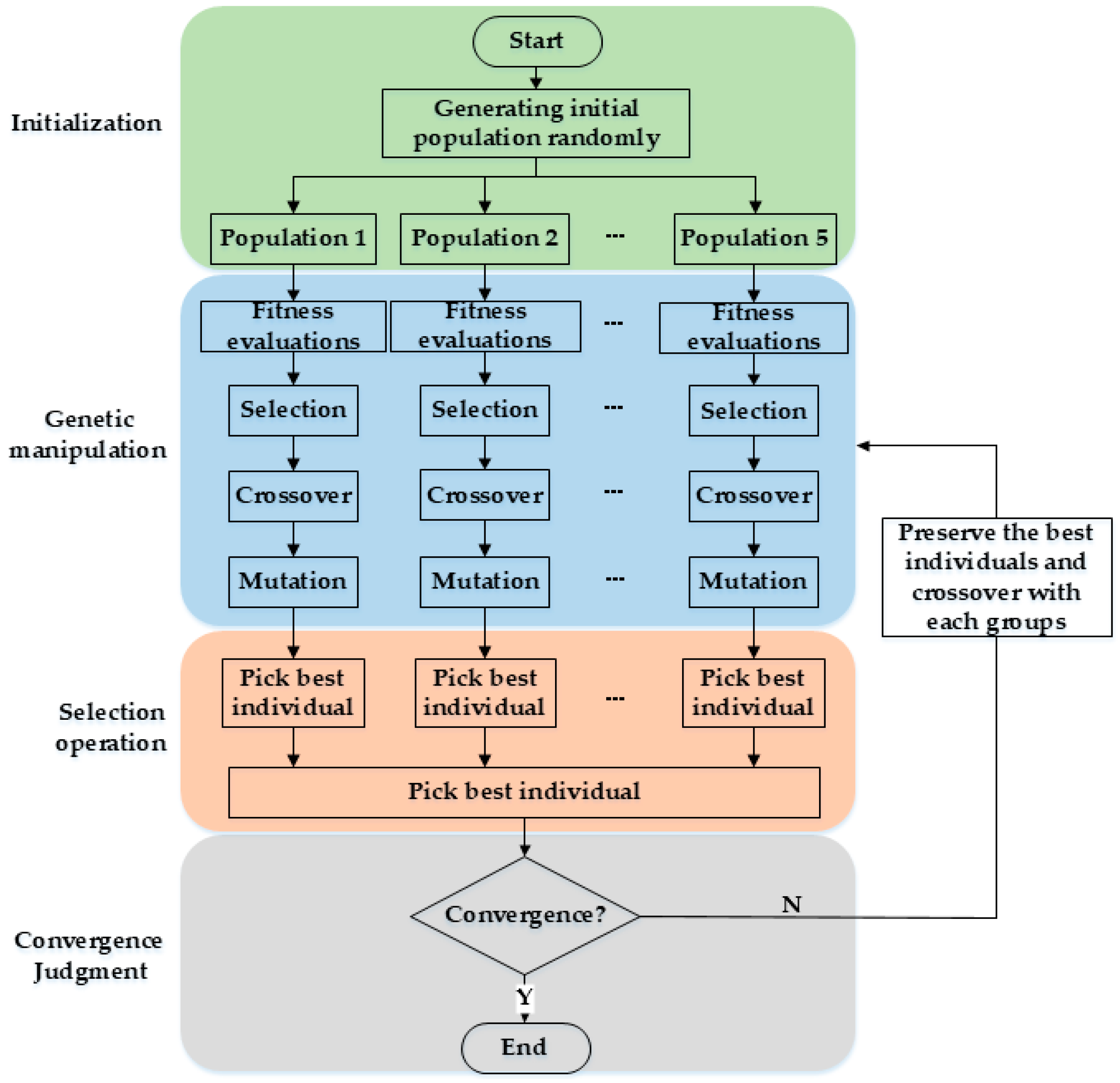
Genetic algorithm (GA) is an algorithm for searching the global optimal solution emulating the survival rule of the fittest, but there is a phenomenon that it is easy to premature. The multi-population genetic algorithm (MPGA) divides a population into several isolated sub-populations, compared to the single population of GA, it is able to raise the parallelism of the genetic execution and is more resistant to premature convergence than that of the single-population [19,20]. The IMPGA also divides the population into several sub-populations, and it assigns different cross-variation rates to each population to improve species diversity. In the evolutionary process, the best individual in each sub-population is saved to the next evolutionary process, and then the best individuals in the population are driven to communicate with each sub-population. Finally, the individual with the highest fitness in the population is found as the optimal solution. In this way, not only the convergence speed can be accelerated, but also the premature problem can be better resisted. The flow chart for IMPGA is shown in Figure 1.
- Gene coding: Use the switch state vector K as the initial gene.
- Generate initial population: Five initial sub-populations were set and 100 individuals were randomly generated in each sub-population.
- Fitness assessment: Calculate the fitness values of all individuals.
- Genetic process: Each population screen excellent individuals through roulette wheel selection algorithm, and carries out genetic operation according to different crossover and mutation probabilities. The r1, r2 are random numbers from 0 to 1, and crossover probability PC and mutation probability Pm of each group are calculated as follows:
- High-quality inheritance: Each sub-population picks out the best individual to save to the next evolutionary process, it avoided the loss of optimal individuals. Then, the best individual in the population was selected, and gene crossover operations were carried out with five individuals in each sub-population during the next evolutionary process, so that all sub-populations could have the opportunity to communicate with the best individuals.
- Convergence judgment: When the optimal individual does not change in the continuous 20 times of evolution, it is judged that the results converge and the optimal solution is obtained.
2.3. Comparison of Simulation Effects of GA, MPGA, IMPGA
By setting the population with gene length of 20, the effect of calculating the Pareto solution of phase-swapping strategy by GA, MPGA and IMPGA were compared. Table 2 shows the parameter settings of each algorithm. Figure 2 shows the evolution process of the three algorithms.
As can be seen from Figure 2a,b, both GA and MPGA lose their optimal solution in the process of evolution, and the algorithm does not converge when the maximum evolution times are reached. Although MPGA increases the probability of finding an optimal solution by setting multiple sub-populations, it does not improve the problem of premature and slow convergence. In Figure 2c, the improved algorithm preserves the optimal solution in the process of evolution, which avoids the loss of the optimal solution. At the same time, it achieves better results than GA and MPGA in both the convergence speed and optimal value.
2.4. Simulation Result
Table 3 lists three sets of distribution system data in three-phase unbalanced state. Each set has 20 user controllers to perform swapping operation. After the simulation experiment with MATLAB 2018, the connection phase of load calculated by IMPGA are obtained.
Table 4 lists three-phase current and three-phase unbalance before and after the treatment of three-phase unbalance.
By comparing the above results, it can be proved that the load phase connection state calculated by IMPGA can significantly reduce the three-phase unbalance, make it reach the prescribed range and only operate the least switching times, and reduce the interference to users, thus making the distribution system more reliable.
3. Three-Phase Unbalanced Treatment Plan
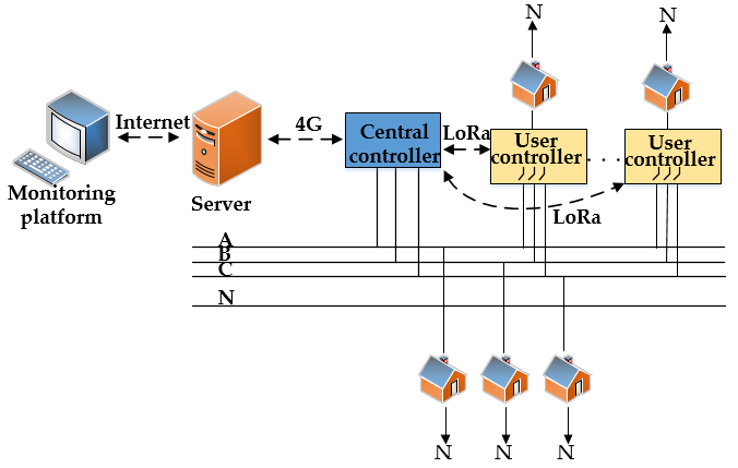
In this paper, the LV residential load transfer device is used to evenly distribute the load to manage the three-phase unbalance problem. The overall structure of the device is shown in Figure 3. It consists of three parts: user controller, central controller, and monitoring platform.
The user controllers were installed at the users’ residence, use three-phase input and single-phase output. The voltage, load current and connection phase information of the user are collected in real time, and then sent them to the central controller. When receiving the control command, microcontroller unit (MCU) controls the magnetic holding relay to perform related actions. The central controller is installed on the output side of the transformer of the LV distribution network, and collects the current data on the three-phase bus in real time. Finally, the three-phase bus current data and user controller data are packaged and uploaded to the server through 4G communication. The monitoring platform can process the data from the server and realize the function of visualization, algorithm realization and sending phase exchange instructions.
This article integrates IMPGA into the monitoring platform when the three-phase unbalance condition is reached; the platform shall sort out the current number of consumers, load current value, phase connection state and three-phase bus current data, and takes them as the input data of the algorithm. Then, the algorithm is called to calculate the phase-swapping strategy, which can obtain the result in a few seconds. Finally, the monitoring platform sends commands to the corresponding user controller to change the user’s connection phase, which can automatically solve the three-phase unbalance problem in the real world.
4. Design of the User Controller and Central Controller
4.1. Implementation Plan of User Controller
The user controller is used as an actuator for load delivery and is designed with the following requirements:
- Online function, that is, to achieve the load transfer without affecting the users’ power consumption.
- Lower impact; will not make the power quality worse.
- Real-time adjustability, when the three-phase unbalance condition is reached, the load transfer action can be performed in time to make the three-phase unbalance rate meet the specified requirements.
- Low cost; can achieve a low price and high efficiency as much as possible.
According to the above requirements, the overall block diagram of the user controller proposed in this paper is shown in Figure 4. It mainly has power information collection function, zero-crossing detection function, phase detection function, relay drive function, and communication function.
4.2. Phase-Swapping Switch with Automatic Adjustment of the Action Point
The load phase-swapping operation of mechanical switches creates transients-overvoltage, inrush current and harmonics. These transients not only inject small disturbance into local and regional system, but also suppress the switching gear and slowly degrade the devices insulation [21]. Therefore, this paper uses the method of a synchronous switch to design the phase-swapping switch.
The synchronous switch is a relay controlled by MCU that is precisely controlled to ensure the minimum current when the circuit is broken and can close the circuit at the minimum voltage. It also overcomes the shortcomings that the thyristor switch is easily damaged in the phase-swapping switch, and the cost is much lower than that of STS.
Due to mechanical dispersion problems, and as the number of switching operations increases, the operating time of the magnetic holding relay will deviate to some extent. The main difficulty in the design of the synchronous switch is that it is difficult to accurately grasp the timing of the switching action. Firstly, the operation time of the switch is calculated to ensure zero-voltage turn-on and zero-current turn-off under any kind of load. After that, the sampling circuit collects the action duration and the action time, and realizes the automatic correction of the action time through software design, which makes the zero-crossing action more accurate. Finally, the software phase-locked design ensures that two-phase short-circuit accidents do not occur during the load transfer process.
4.2.1. Calculation of the Best Action Time
The phase angle of each phase voltage in the three-phase system is 120° apart. When calculating the driving timing of the switching action, it can be divided into two cases:
1. Switching to the leading phase, that is, phase A to phase C, phase B to phase A, or phase C to phase B.
2. Switch to the lag phase, that is, phase A to phase B, phase B to phase C, or phase C to phase A.
In Figure 5, the command of switching to the leading phase is received at . First, the zero-crossing of the leading phase voltage will trigger the calculation of the time interval from the voltage zero-crossing point T2 to the current zero-crossing point T3.
Then, according to the relay disconnection travel time , the delay drive time required to achieve zero-current turn-off can be calculated, and the delay drive time required for zero-voltage turn-on can also be calculated by . Ta is the interval time between relay from turn-off to turn-on. In order to avoid the two-phase short-circuit accidents, the Ta interval time in this design is set to be greater than 10 ms, so Ta = 20 − t when t < 10 ms, which will make the relay turn-on at zero voltage. When t > 10 ms, the turn-on time of relay needs to be delayed by half a cycle, so Ta = 30 − t. The calculation method is as follows:
Switching to the lagging phase is another process. As we can see in Figure 6, zero-current is firstly detected as the trigger signal to calculate the time interval and delayed drive time . The calculation formula is as follows:
4.2.2. Automatic Correction Design of Action Time
In order to avoid the inability to accurately operate at the zero-crossing due to problems such as mechanical dispersion and equipment aging, the circuit of Figure 7 is used to collect information about the duration of the switching action and , and the connection phase state.
The circuit of Figure 7 uses a bidirectional optocoupler to perform the acquisition. When the relay is closed, the circuit is turned on and the voltage comparator outputs a high level. Therefore, by calculating the times of the relay driving point to the circuit conduction point , the relay closing operation time can be obtained. The time of the relay closing action was measured 5 times and is the average value of the closed action.
4.2.3. Software Design of Phase-Locked Function
In order to avoid that two-phase short-circuit accident due to caused by relay failure or arcing, through the design of the software, if the circuit is not broken within the specified time during the phase-swapping operation, the next action will not be performed. The flow chart of phase-locked design is shown in Figure 8.
4.3. Implementation Plan of Central Controller
The central controller is used as the core of online governance for three-phase unbalance. It collects three-phase current data at the output of the LV distribution transformer and acts as a medium for communication between the user controller and the server, enabling to implement online governance functions. Therefore, when the three-phase unbalance condition is reached, the monitoring platform can send a phase exchange command to the user controller through the central controller. The overall block diagram of the central controller proposed in this paper is shown in Figure 9.
The central controller is mainly composed of mutual inductors, analog-to-digital converter (ADC), MCU, power supply system, LoRa wireless communication module, 4G communication module and so on.
4.4. Design and Implementation of a Wireless Communication System
In order to meet the requirements of the residential load transfer device in the long-distance, small data transmission, low power consumption and low cost in practical applications, a LV wide-area network information monitoring approach based on LoRa + 4G is proposed in this paper.
The system block diagram is shown in Figure 10. The user controller only contains the LoRa module and we call it the subnode in the communication system. The central controller contains LoRa and 4G modules, which is called the main node. The communication system mainly includes the subnode, main node, and server. The subnode collects user voltage, current and connection phase information, and conducts point-to-point communications with the main node by LoRa communication module. The function of the main node is to receive information from the subnode and server and process the received information. The server acts as a MQTT broker and forwards the received information. The user can use the monitoring platform to monitor the user controller through the Internet [22,23].
5. Establishment of Intelligent Monitoring Platform
5.1. Introduction to MQTT Protocol
As is shown in Figure 11, MQTT protocol contains three identities: publisher, subscriber, and MQTT broker. The information exchange between clients is realized through the MQTT broker. The intelligent monitoring platform and the central controller act as clients, and the message subscription mode enables the monitoring platform to implement monitoring functions for multiple stations. Meanwhile, the subscription function can facilitate and quickly monitor the user controller constructed in the later stage.
By writing the MQTT protocol program in the MCU of the central controller, network connection, subscribe and publish functions can be realized. The data is published to the MQTT server according to the customized message format, and the monitoring platform receives the corresponding data by subscribing function, then analyzes the data to implement monitoring of the user controller.
5.2. Design and Implementation of Monitoring Platform
The monitoring platform is designed and developed by Visual Studio, Net Framework and C++ language. It can monitor the central controller and the user controller, at the same time, it can send commands to any user controller to perform corresponding operations. The platform designs a local database to store the current data information for future analysis. The intelligent monitoring platform is shown in Figure 12. Figure 13 shows the workflow of the monitoring platform.
In order to carry out IMPGA in the monitoring platform, the script program written by MATLAB is packaged into IMPGA.dll file by .NET Assembly tool. Then add MWArray, a toolkit that can convert MATLAB data to NET data, and IMPGA.dll to VS. The input data of the algorithm are n, K, Ii, IM (IMA, IMB, IMC), and the output data are optimal state of connection phase (OP), numbers of user controllers performing phase swapping (NPP), M(K) and B(K).
The monitoring platform receives the data and calculates the three-phase unbalance rate every 5 minutes. When the three-phase unbalance rate exceeds 15% for more than 3 times within 30 minutes, it is considered that the three-phase unbalance event occurs and then calculates the swapping strategy. First, these input signals are arranged into an array, and then converted into the language that MATLAB can recognize using MWArray. Next, IMPGA is called, and the algorithm can be realized on the monitoring platform to obtain the optimal swapping strategy. After sorting out the calculation results, the corresponding commands are sent for swapping action, so that the three-phase load is evenly distributed.
6. Experimental Result
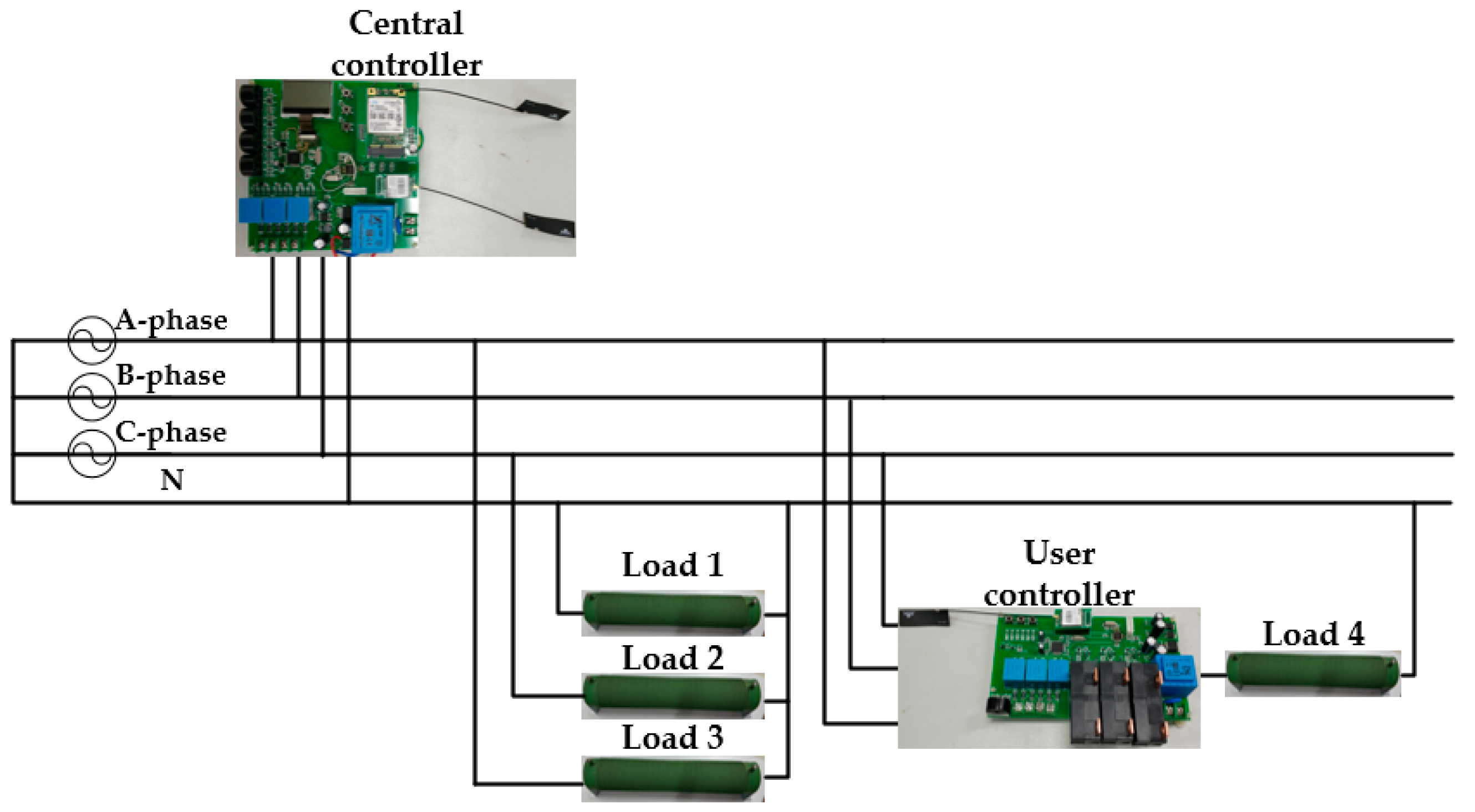
In order to verify the effectiveness of the design, a circuit with three-phase unbalanced state was built, which proved that the residential load transfer device can effectively solve the three-phase unbalance problem. It also proves that the user controller has the ability of zero-voltage turn-on and zero-current turn-off, making the load transmission process smooth and ensuring good power quality. The circuit diagram is shown in Figure 14, and the practice experimental diagram is shown in Figure 15.
In Figure 16a, the function of zero-current turn-off of the phase-swapping switch is shown, and the function of zero-voltage turn-on is realized in Figure 16b. In this actual experiment, the precise operation of phase swapping and the function of automatically adjusting operation time point are proved. In Figure 16c, a three-phase unbalance event occurs, and then the phase-swapping switch is driven to perform a load exchange operation to achieve uniform load distribution and reduce the three-phase unbalance.
7. Conclusions
To solve the problem of three-phase unbalance of LV distribution network, a residential load transfer device was designed, and a phase-swapping strategy algorithm based on an IMPGA was proposed. From the above results, it can be seen that the equipment can monitor users’ electricity consumption and three-phase unbalance rate on the platform, which realizing the visualization function, that the power supply company can find and eliminate some faults in the distribution network in time. The device realizes the function of algorithm on the monitoring platform. When three-phase unbalance events occur, the optimal phase-changing strategy is automatically calculated and the corresponding switch is remotely controlled to perform the phase-swapping action, which reduces the risk of distribution transformer damage and improves the power quality. On the economic level, the device reduces line loss and manual commutating operation costs, and the visual function reduces the risk of distribution system equipment damage to a certain extent. In addition, in order to reduce the deployment cost of wireless communication, the LoRa communication module adopted in this paper has the characteristics of low cost, only about $4, and it works in the global free frequency band, that don’t need additional communication costs. Compared with the high labor cost and equipment maintenance cost, the scheme designed in this paper has a higher economic benefit. The phase-swapping scheme of magnetic latching relay can also reduce the cost. Currently, the price of three magnetic latches with a maximum load of 100A on the market is less than $30, while the price of STS is usually more than $100. Therefore, this design has a huge cost advantage over the design in the references. The effectiveness of the switch in load transfer is verified by practical experiments, and the proposed algorithm is verified by simulation experiments.
Author Contributions
Conceptualization, investigation, and resources, G.B.; formal analysis, methodology, software, and visualization, S.K.
Funding
This research received no external funding.
Conflicts of Interest
The authors declare no conflicts of interest.
Nomenclatures
| Abbreviations | |
| LV | Low-voltage |
| 4G | 4th generation mobile telecommunications |
| LoRa | Long Range |
| IMPGA | Improved multi-population genetic algorithm |
| PSO | Particle swarm optimization |
| STS | Static Transfer Switches |
| SD | Standard |
| GA | Genetic algorithm |
| MPGA | Multi-population genetic algorithm |
| MCU | Microcontroller unit |
| MQTT | Message Queuing Telemetry Transport |
| ADC | Analog-to-digital converter |
| OP | Optimal state of connection phase |
| NPP | Number of user controllers performing phase swapping |
| Parameters | |
| Ii | User loads for installed user controllers (i = 1,2,...,n) |
| I | Vectors of user loads for all installed user controllers |
| k | User phase connection for installed user controller |
| K | User phase connection vector for all installed user controllers |
| ts | User phase connection column vector for installed user controller |
| T | User phase connection matrix for all installed user controllers |
| IA, IB, IC | The three-phase current of the user controller |
| IMA, IMB, IMC | The current on the three-phase busbar |
| IGA, IGB, IGC | The total three-phase current of the user who has not installed the controller |
| Imax, Imin | Maximum and minimum currents of three-phase busbar |
| B(K) | Three-phase unbalance rate |
| ε1 | Minimum unbalance rate coefficient |
| m | Transformation factor |
| M(K) | The times of phase swapping switch actions |
| ε2 | Minimum number of actions coefficient |
| r1, r2 | Random numbers from 0 to 1 |
| Pc | Cross probability coefficient |
| Pm | Mutation probability coefficient |
| t | Time interval between voltage zero-crossing point and current zero-crossing point |
| T1 | The time that issue load transfer instructions |
| T2, T3 | The time that zero-crossing |
| T4 | The time that control the relay turn-off |
| T5 | The time that relay break |
| T6 | The time that control the relay turn-on |
| T7 | The time that relay close |
| Tdc | The delay time to turn-off the relay |
| Tc | Duration of relay breaking action |
| Tdo | The delay time to turn-on the relay |
| To | Duration of relay closing action |
| Ta | The time interval between relay turn-off and turn-on |
| n | Numbers of connected user controllers |
References
- Ali, B.; Siddique, I. Distribution System Loss Reduction by Automatic Transformer Load Balancing. In Proceedings of the 2017 International Multi-Topic Conference (INMIC), Lahore, Pakistan, 24–26 November 2017; pp. 1–5. [Google Scholar]
- Rao, B.V.; Kupzog, F.; Kozek, M. Phase Balancing Home Energy Management System Using Model Predictive Control. Energies 2018, 11, 3323. [Google Scholar] [CrossRef]
- Ma, K.; Li, R.; Li, F. Utility-Scale Estimation of Additional Reinforcement Cost from Three-Phase Imbalance Considering Thermal Constraints. IEEE Trans. Power Syst. 2017, 32, 3912–3923. [Google Scholar] [CrossRef]
- Hooshmand, R.A.; Soltani, S. Fuzzy Optimal Phase Balancing of Radial and Meshed Distribution Networks Using BF-PSO Algorithm. IEEE Trans. Power Syst. 2012, 27, 47–57. [Google Scholar] [CrossRef]
- Sreenivasarao, D.; Agarwal, P.; Das, B. Neutral current compensation in three-phase, four-wire systems: A review. Electr. Power Syst. Res. 2012, 86, 170–180. [Google Scholar] [CrossRef]
- Von Jouanne, A.; Banerjee, B. Assessment of voltage unbalance. IEEE Trans. Power Deliv. 2001, 16, 782–790. [Google Scholar] [CrossRef]
- Wang, X.; Dai, K.; Chen, X.; Zhang, X.; Wu, Q.; Dai, Z. Reactive Power Compensation and Imbalance Suppression by Star-Connected Buck-Type D-CAP. Energies 2019, 12, 1914. [Google Scholar] [CrossRef]
- Liu, Y.-W.; Rau, S.-H.; Wu, C.-J.; Lee, W.-J. Improvement of Power Quality by Using Advanced Reactive Power Compensation. IEEE Trans. Ind. Appl. 2018, 54, 18–24. [Google Scholar] [CrossRef]
- Gungor, V.C.; Sahin, D.; Kocak, T.; Ergut, S.; Buccella, C.; Cecati, C.; Hancke, G.P. Smart Grid Technologies: Communication Technologies and Standards. IEEE Trans. Ind. Inform. 2011, 7, 529–539. [Google Scholar] [CrossRef] [Green Version]
- Fang, X.; Misra, S.; Xue, G.; Yang, D. Smart Grid—The New and Improved Power Grid: A Survey. IEEE Commun. Surv. Tutor. 2012, 14, 944–980. [Google Scholar] [CrossRef]
- Farhangi, H. The Path of the Smart Grid. IEEE Power Energy Mag. 2010, 8, 18–28. [Google Scholar] [CrossRef]
- Li, F.; Qiao, W.; Sun, H.; Wan, H.; Wang, J.; Xia, Y.; Xu, Z.; Zhang, P. Smart Transmission Grid: Vision and Framework. IEEE Trans. Smart Grid. 2010, 1, 168–177. [Google Scholar] [CrossRef]
- Popoola, O.; Jimoh, A.; Nicolae, D. On-Line Remote and Automatic Switching of Consumers’ Connection for Optimal Performance of a Distribution Feeder. In Proceedings of the AFRICON 2007, Windhoek, South Africa, 26–28 September 2007; pp. 1–6. [Google Scholar]
- Siti, M.W.; Jimoh, A.A.; Nicolae, D.V. Phase load balancing in the secondary distribution network using fuzzy logic. In Proceedings of the AFRICON 2007, Windhoek, South Africa, 26–28 September 2007; pp. 1–7. [Google Scholar]
- Shahnia, F.; Wolfs, P.J.; Ghosh, A. Voltage Unbalance Reduction in Low Voltage Feeders by Dynamic Switching of Residential Customers among Three Phases. IEEE Trans. Smart Grid. 2014, 5, 1318–1327. [Google Scholar] [CrossRef]
- Kalesar, B.M. Customers swapping between phases for loss reduction considering daily load profile model in smart grid. In Proceedings of the CIRED Workshop 2016, Helsinki, Finland, 14–15 June 2016; pp. 1–4. [Google Scholar]
- Siti, M.W.; Nicolae, D.V.; Jimoh, A.A.; Ukil, A. Reconfiguration and Load Balancing in the LV and MV Distribution Networks for Optimal Performance. IEEE Trans. Power Deliv. 2007, 22, 2534–2540. [Google Scholar] [CrossRef]
- Pasdar, A.; Mehne, H.H. Intelligent three-phase current balancing technique for single-phase load based on smart metering. Int. J. Electr. Power Energy Syst. 2011, 33, 693–698. [Google Scholar] [CrossRef]
- Hong, T.-P.; Peng, Y.-C.; Lin, W.-Y.; Wang, S.-L. Empirical comparison of level-wise hierarchical multi-population genetic algorithm. J. Inf. Telecommun. 2017, 1, 66–78. [Google Scholar] [CrossRef] [Green Version]
- Su, Y.; Chi, R. Multi-objective particle swarm-differential evolution algorithm. Neural Comput. Appl. 2017, 28, 407–418. [Google Scholar] [CrossRef]
- Sun, R.; McVey, M.; Yang, D.; Stage, J.R. A Study of Synchronous Breaker Switching with Preinsertion Resistor for Capacitors Banks. IEEE Trans. Power Deliv. 2018, 33, 821–829. [Google Scholar] [CrossRef]
- Zhang, X.; Zhang, M.; Meng, F.; Qiao, Y.; Xu, S.; Hour, S. A Low-Power Wide-Area Network Information Monitoring System by Combining NB-IoT and LoRa. IEEE Internet Things J. 2019, 6, 590–598. [Google Scholar] [CrossRef]
- Hwang, H.C.; Park, J.S.; Shon, J.G. Design and Implementation of a Reliable Message Transmission System Based on MQTT Protocol in IoT. Wirel. Pers. Commun. 2016, 91, 1765–1777. [Google Scholar] [CrossRef]
Figure 1.
Flow chart of improved multi-population genetic algorithm (IMPGA).

Figure 2.
The evolutionary process of different algorithms: (a) Evolutionary process of the traditional genetic algorithm; (b) evolutionary process of the multi-population genetic algorithm; (c) evolutionary process of IMPGA.
Figure 2.
The evolutionary process of different algorithms: (a) Evolutionary process of the traditional genetic algorithm; (b) evolutionary process of the multi-population genetic algorithm; (c) evolutionary process of IMPGA.

Figure 3.
The overall frame of residential load transfer device.

Figure 4.
Structure of the user controller.

Figure 5.
Sequence diagram of switch to the leading phase.

Figure 6.
Sequence diagram of switch to lag phase.

Figure 7.
Action time acquisition circuit.

Figure 8.
Flow chart of phase-locked function.

Figure 9.
System structure diagram of central controller.

Figure 10.
Wireless communication framework.

Figure 11.
Message Queuing Telemetry Transport (MQTT) model.

Figure 12.
Intelligent monitoring platform.

Figure 13.
The workflow of the platform.

Figure 14.
Experimental circuit diagram.

Figure 15.
Practice experiment diagram.

Figure 16.
The current waveform of the switching action in the actual experiment. (a) Zero-current turn-off. (b) Zero-voltage turn-on. (c) Load transfer operation.
Figure 16.
The current waveform of the switching action in the actual experiment. (a) Zero-current turn-off. (b) Zero-voltage turn-on. (c) Load transfer operation.


Table 1.
Several pieces of research about phase-swapping strategy algorithms and phase-swapping switches.
Table 1.
Several pieces of research about phase-swapping strategy algorithms and phase-swapping switches.
| Type | Author(s) | Methods | Effectiveness Analysis |
|---|---|---|---|
| Research on phase switching strategy algorithm | M.W. Siti et al. [14] | Fuzzy logic operation with minimizing power loss as objective function | Too many switching actions and has a large amount of calculation. |
| Farhad Shahnia et al. [16] | Genetic algorithm with voltage imbalance and penalty factor as objective function | Convergence is faster, but it is easy to premature, and too many switching actions | |
| Belal Mohamadi Kalesar et al. [17] | Particle swarm optimization with minimizing power loss as objective function | Easy to premature, and too many switching actions | |
| Mukwanga W et al. [18] | A heuristic method with minimizing power loss as objective function | Historical data is required for training, and the problem of frequent switching is not considered. | |
| A. Pasdar et al. [19] | Ant colony algorithm with minimizing unbalanced current as objective function | Convergence is slow, easy to premature, and the problem of frequent switching is not considered. | |
| Research on phase-swapping switch | Mukwanga W et al. [18] | STS | Higher precision and better reliability |
| A. Pasdar et al. [19] | Relay | Low cost |
Table 2.
Parameter settings of each algorithm.
| Algorithm Type | Population Size | Number of Population | Crossover Probability | Mutation Probability | Maximum Number of Evolutions |
|---|---|---|---|---|---|
| GA | 100 | 1 | 0.2 | 0.2 | 200 |
| MPGA | 100 | 5 | 0.2 | 0.2 | 200 |
| IMPGA | 100 | 5 | 0.2 + 0.4 × r1 | 0.15 + 0.1 × r2 | 200 |
Table 3.
Comparison of effects before and after three-phase unbalanced treatment.
| Consumer Number | 1st Data Set | 2nd Data Set | 3rd Data Set | ||||||
|---|---|---|---|---|---|---|---|---|---|
| IL(A) | Initial Phase | After IMPGA | IL(A) | Initial Phase | After IMPGA | IL(A) | Initial Phase | After IMPGA | |
| 1 | 8 | A | A | 8 | A | A | 27 | A | A |
| 2 | 4 | A | A | 27 | A | A | 26 | A | A |
| 3 | 3 | A | A | 15 | A | A | 16 | A | A |
| 4 | 21 | A | A | 27 | A | A | 22 | A | A |
| 5 | 11 | A | A | 25 | A | C | 29 | A | C |
| 6 | 8 | A | A | 2 | A | A | 17 | A | A |
| 7 | 14 | A | A | 29 | A | A | 26 | A | B |
| 8 | 14 | A | A | 20 | A | A | 26 | A | A |
| 9 | 10 | B | B | 5 | A | A | 4 | A | A |
| 10 | 10 | B | B | 20 | B | B | 25 | B | B |
| 11 | 24 | B | B | 14 | B | B | 13 | B | B |
| 12 | 15 | B | B | 25 | B | B | 10 | B | B |
| 13 | 29 | B | A | 27 | B | B | 19 | B | B |
| 14 | 9 | B | B | 9 | B | B | 3 | B | B |
| 15 | 20 | C | C | 23 | B | B | 5 | B | B |
| 16 | 29 | C | C | 28 | C | C | 14 | C | C |
| 17 | 18 | C | C | 20 | C | C | 21 | C | C |
| 18 | 3 | C | C | 3 | C | C | 27 | C | C |
| 19 | 21 | C | C | 1 | C | C | 4 | C | C |
| 20 | 29 | C | C | 25 | C | C | 19 | C | C |
Table 4.
The results comparison.
| Results | Initial State | After IMPGA | Initial State | After IMPGA | Initial State | After IMPGA |
|---|---|---|---|---|---|---|
| IMA | 211 | 240 | 271 | 246 | 321 | 266 |
| IMB | 278 | 249 | 268 | 268 | 211 | 237 |
| IMC | 224 | 224 | 212 | 237 | 208 | 237 |
| B(K) | 24.1% | 10.4% | 21.7% | 11.6% | 35.2% | 10.9% |
© 2019 by the authors. Licensee MDPI, Basel, Switzerland. This article is an open access article distributed under the terms and conditions of the Creative Commons Attribution (CC BY) license (http://creativecommons.org/licenses/by/4.0/).
Share and Cite
MDPI and ACS Style
Bao, G.; Ke, S. Load Transfer Device for Solving a Three-Phase Unbalance Problem Under a Low-Voltage Distribution Network. Energies 2019, 12, 2842. https://doi.org/10.3390/en12152842
AMA Style
Bao G, Ke S. Load Transfer Device for Solving a Three-Phase Unbalance Problem Under a Low-Voltage Distribution Network. Energies. 2019; 12(15):2842. https://doi.org/10.3390/en12152842
Chicago/Turabian StyleBao, Guanghai, and Sikai Ke. 2019. "Load Transfer Device for Solving a Three-Phase Unbalance Problem Under a Low-Voltage Distribution Network" Energies 12, no. 15: 2842. https://doi.org/10.3390/en12152842
Note that from the first issue of 2016, this journal uses article numbers instead of page numbers. See further details here.