Driven Primary Regulation for Minimum Power Losses Operation in Islanded Microgrids
by
 , , and
Quynh T.T Tran
1,* ,
,
Maria Luisa Di Silvestre
2 ,
,
Eleonora Riva Sanseverino
2,
Gaetano Zizzo
2 and
and
Thanh Nam Pham
3 1
Institute of Energy Science, Vietnam Academy of Science and Technology, Hanoi 10000-04, Vietnam
2
Department of Energy, Information Engineering and Mathematical Models, University of Palermo, 90128 Palermo, Italy
3
Faculty of Electrical Engineering, Electric Power University, Hanoi 10000-04, Vietnam
*
Author to whom correspondence should be addressed.
Energies 2018, 11(11), 2890; https://doi.org/10.3390/en11112890
Submission received: 1 September 2018
/
Revised: 18 October 2018
/
Accepted: 19 October 2018
/
Published: 24 October 2018
(This article belongs to the Special Issue The Digital Revolution in Future Power Distribution and Microgrids)
Abstract
:The paper proposes an improved primary regulation method for inverter-interfaced generating units in islanded microgrids. The considered approach employs an off-line minimum losses optimal power flow (OPF) to devise the primary frequency regulation curve’s set-points while satisfying the power balance, frequency and current constraints. In this way, generators will reach an optimized operating point corresponding to a given and unique power flow distribution presenting the minimum power losses. The proposed approach can be particularly interesting for diesel-based islanded microgrids that face, constantly, the issue of reducing their dependency from fossil fuels and of enhancing their generation and distribution efficiency. The Glow-worm Swarm Optimization (GSO) algorithm is selected as a key heuristic tool for solving the optimization problem. The main program is carried out in Matlab environment. A case study with a parametric analysis is implemented and all results are assessed and compared with the conventional droop control method to show the effectiveness of the proposed method as well as the improved reliability of the system.
1. Introduction
In the last years, thanks to the development of new devices and new technologies and the wide use of information and communications technology (ICT) in power systems, microgrids have become an effective solution for providing electricity at small scale using various distributed energy sources and energy storage systems. Microgrids are flexible systems that can be operated either in grid-connected or in islanded mode [1]. When operated in grid-connected mode, microgrids purchase electricity from the main grid to control voltage and power balance [2] or sell unused electricity to the main grid for maximizing the operational benefits [3]. When operated in islanded mode, microgrids operate independently from the main grid and the management of voltage and frequency are the most important operations to enhance the optimal generated power sharing while stabilizing the system [4]. The generated power sharing problem is implemented at different control levels (primary, secondary and tertiary regulation) with various time scales from milliseconds to minutes.
Recently, studies about droop control for microgrid systems have focused on finding solutions for improving system stability. As an example, in [5], a new scheme for the control of parallel-connected inverters in an islanded microgrid was presented. The study uses the feedback from those variables that can be measured locally at the inverter. In this way it is not necessary to establish a communication flow of control signals between the devices, with high advantages for large microgrids, where distances between inverters make communication impractical. In [6] the authors propose a new methodology for quickly and accurately calculating the average power for single-phase paralleled inverters intended to be applied in a droop-control microgrid system. In [7], the authors face the issue of frequency stabilization of islanded microgrids through Demand Response and generation-side management, using droop control and allowing them to share imbalances. Finally, in [8] the authors propose a direct current vector control mechanism integrated in the droop control method for improving microgrid’s stability, relibility and power quality.
There are three most famous droop control methodologies in the literature: linear, nonlinear and dynamic droop control. Linear (or conventional) droop control is based on the use of a constant droop coefficient for each distributed generator (DG). This type of control is executed as a primary control to regulate frequency and voltage in a microgrid and to devise the power sharing between the DGs involved in the regulation. The issue is very relevant as demonstrated by the scientific literature [9]. As an example, in [10] the authors study the problem of droop control in microgrids with highly-resistive lines. In [11], a model for islanded microgrids with droop control is proposed, introducing a suitable state-space transformation that allows writing the closed-loop model in an explicit state-space form. Then, the authors adopt the singular perturbations technique to obtain reduced order models that reproduce the stability properties of the original closed-loop model.
In [5,12], the authors present two different problems about controlling parallel-connected inverters by using linear droop control in an islanded supply system, without communicating control signals between the inverters. In [13], the linear droop control method is used to find the best placement and operation mode for DG units in islanded microgrids. The paper only focuses on minimum fuel consumption cost and voltage stability issues and does not include frequency constraints.
The non-linear and dynamic droop control rely on more complicated functions and are difficult to apply broadly. In nonlinear droop control, the frequency and voltage of the system are changed as a function of the optimized sharing between the DGs of the active and reactive power, respectively. In [14] the authors apply this method to minimize the operating cost, verifying the effectiveness of the method in an experimental case study. The nonlinear-droop control is also mentioned in [15,16,17] where the authors propose different approaches to this issue.
Finally, dynamic droop control uses dynamic signals, like voltage and frequency reference values, to regulate the output power of the generators. In [18], a dynamic droop control methodology is applied to improve the quality of power system stability in presence of variability of renewable energy sources in an islanded microgrid. Another research study adopted the same methodology to regulate the active power flow following the frequency values at no load to reduce the fuel cost of DGs [19]. A dynamic power sharing method for minimum operation costs is mentioned in [20]. However, results are just focused on the sharing of power to attain minimum operational cost without considering frequency limitations. Another dynamic droop control method is applied in [21] to regulate the frequency in presence of wind generators and solve stability problems. In this case, an efficient droop control allows extracting the maximum available power from wind turbines regardless of the wind speed. Table 1 summarizes the above analysis highlighting the advantages and disadvantages of the various approaches present in literature.
In this paper, a driven primary regulation method, based on simple and easy to implement algorithms, is proposed with the aim of minimizing the power losses in an isolated microgrid. Based on the optimal power flow procedure, the droop coefficients in the droop control function are adjusted following the variation of the loading conditions, and a unique piecewise droop curve for the controlled generator is built from a set of optimized operating points. In this way, the distributed generator’s power output can be adjusted more flexibly, the operational efficiency of microgrid is increased, and the power losses are reduced. The novelty of the paper, with respect to the state of the art, is, therefore, the use of non-costant droop coefficients in order to enhance the overall efficiency of the microgrid while preserving its stability. This issue is of particular interest for diesel-based islanded microgrids that face, constantly, the issue of reducing their dependency from fossil fuels and of enhancing the quality of the supply, also reducing voltage drops and power losses.
From a technical point of view, the contributions of the paper are listed below: (1) The proposed primary droop regulation improves the overall efficiency of the microgrid by adopting a Glow-worm Swarm Optimization (GSO) procedure. (2) The proposed primary droop regulation keeps frequency within desired limits and can relieve also volumes that secondary and tertiary regulation have to take over from primary control, if limited load-generators variations occur in the microgrid. (3) The model for implementing the system in Matlab/Simulink (R2017b, Palermo, Italy) environment is fully described. (4) The approach is tested under dynamic conditions in simulation environment for giving good results.
The paper extends previous work of the same authors [22] where a case study showing the advantages of the proposed approach was discussed. In this work, the mathematical approach is described in details, clarifying some important aspects of the implemented model and providing new simulation results for showing the effectiveness of the method. Moreover, the optimal power flow formulation is enhanced by taking into account the ampacity of the microgrid’s lines as a new constraint and considering the dependence of the system loads on frequency and bus voltages. In this way, the loads representation is more accurate and, as a consequence, the achieved simulation results are improved.
The paper includes four sections, as described below. Section 2 introduces the proposed primary regulation technique for minimum power losses operation and the advantages of the new method compared to the conventional droop control. Finally, it contains the description of the GSO algorithm that is used to solve the optimal power flow (OPF) problem. Moreover, the section describes the implementation in Matlab/Simulink environment; such implementation is useful to check the effectiveness of the proposed method as well as its improved reliability. Section 3 presents the analysis of a case study. Section 4 contains a discussion on the results of the simulations. The results show the dependency between the droop coefficient value and the system operating point and how the proposed regulation method can be used to reduce the power losses in the microgrid. Finally, Section 5 reports the conclusion of the work.
2. Driven Primary Regulation for Minimum Power Losses Operation
The droop control is a control method that is widely used to regulate frequency and voltage and to adjust the power sharing between the generators in a microgrid. In the following, a comparison between the linear droop control method and the new primary regulation method is presented, considering, as an example, the system in Figure 1, including i distributed generators (DG1, DG2,…, DGi) connected to a load bus.
2.1. Conventional Droop Control Method
The linear droop control technique is shown in Equations (1) and (2) [5]:
where PGi and QGi are the real and reactive power generated by the i-th generator; KGi and Kdi are the frequency and voltage droop coefficient of the i-th generator; fx,i and Vi are the frequency and output voltage at the i-th generator; f0i and V0i are the frequency and voltage of the i-th generator at no load.
In the conventional droop control method, the droop coefficient KGi of the i-th generator is typically taken at its maximum value KGmaxi, namely the ratio between the maximum output power PGmaxi (rated power) and the maximum frequency deviation:
where fmin is the frequency lower limit [16].
Since fxi is the same for all the generators in the microgrid, from Equation (1) it derives that the real power sharing between the generators is function of the droop coefficients KGi. Moreover, the microgrid operating frequency fx can be written for the generic i-th generator as it follows:
When the load increases, the microgrid operating frequency varies from fx to f’x and the new value must be comprised in between the minimum acceptable frequency fmin and the maximum acceptable frequency fmax [23].
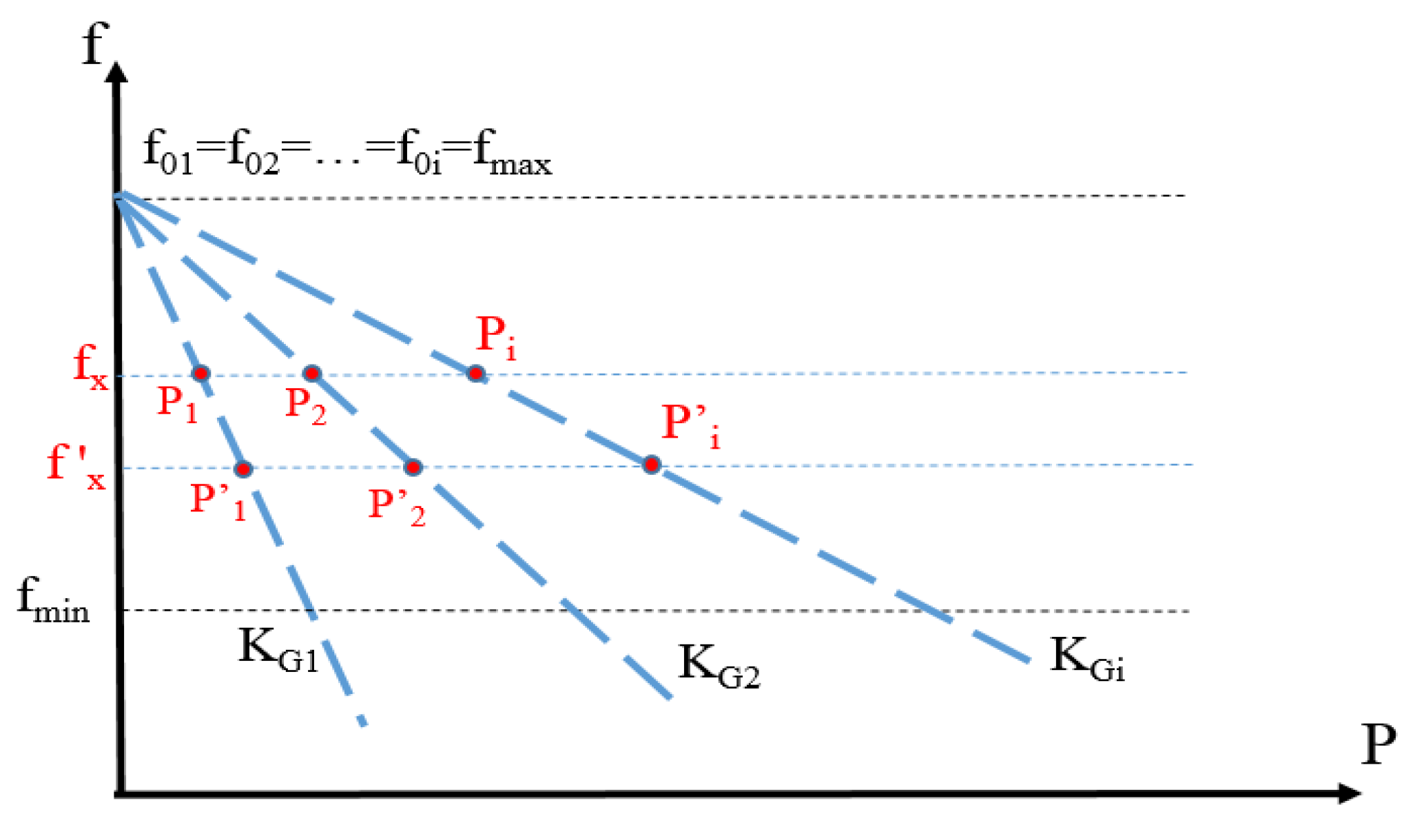
Figure 2 illustrates the variation of the microgrid operating frequency fx as a function of the real power generated by DG1, DG2, …, DGi. When the load increases, the active power of DG1 changes from P1 to P’1, the active power of DG2 changes from P2 to P’2, etc.… It is observed that, in standard linear droop control, the change of the real power demand of the generic i-th generator always stays proportional to its rated power. As shown in Figure 2, the real power demand variation leads to a slight change of the microgrid operating frequency fx and after a few oscillations, the frequency of the system is again stable at a new microgrid operating frequency f’x. The strength of conventional droop control is in its simplicity and reliability, but power sharing based on rated power cannot provide a good solution for optimization problems.
2.2. Proposed Driven Primary Regulation Method
In the literature, some examples can be found showing that, in practical applications, KG can be adjusted [24]. For example, in [25], it is proved that the coefficient KG of wind turbine is not constant. When wind direction and speed fluctuate, the output power changes and this means that the real power of the wind generator transferred to the primary frequency control changes. As a consequence, the value of KG should be picked out under various wind speeds. It is worth to highlight that, also in [2,19], different droop relations are required to resynchronize the system in different operating conditions.
The proposed driven primary regulation method for inverter-interfaced units in isolated microgrids presented in the following is an expansion of the conventional droop control method described in Section 2.1. The new droop curves are built by changing the load in the microgrid and assessing through the OPF the relevant value of KGi, which is considered as the only adjustable parameter producing a new real power sharing among the two generators. The droop coefficients KGi of all the generators are selected optimally in a given range [KGmini; KGmaxi], according to the limitations of output power and frequency. For every load condition, an OPF problem is solved for finding a minimum–losses operating state, assuming that every generator is able to regulate its frequency droop coefficient.
The OPF underlying the construction of the piecewise linear droop control law is formulated as indicated in [26]. The objective of the OPF problem is the minimization of the power losses of the microgrid and can be written as it follows:
where nbus is the total number of buses of the microgrid and is the injected power at bus i given by:
where Vi and Vj are the voltages at buses i and j, respectively; δi and δj are the phase angles of the voltages at bus i, j; Yij is the admittance of the ij branch; θij is the phase angle of Yij; nbr is the number of branches connected to bus i.
The OPF is solved considering the following constraints:
where nG is the number of generators in microgrid; nd is the number of load buses; PGi is the real power generated by DGi; PLi is the real power demand of the i-th load; Ploss indicates the total real power losses of migrogrid; Ibranchj is the current flowing in the j-th branch of microgrid; Imaxbranchj is the ampacity of the j-th branch of microgrid and nbranch is the number of transmission branch in the microgrid.
In the problem formulation, loads are modeled as frequency and voltage dependent terms, as expressed below [27]:
where ∆f is the frequency deviation; P0i and Q0i are the real and reactive power of the load in the operating point; α, β are the real and reactive power exponents [3,28]; Kpf is a coefficient ranging from 0 to 3.0; Kqf is a coefficient ranging from −2.0 to 0 [27].
The coefficients KGi are the decision variables of the optimization problem, although they are not explicitly appearing in the objective function (5), they are contained in the expression (1) of generated powers in inverter interfaced units. The solution found for each load condition is an optimal operating point characterized the following state variables:
- The amplitude and displacement of the voltage phasors at the P–Q buses.
- The amplitude and displacement of the voltage phasors at all the P–V buses except the reference bus (Qi depends on Vi by (2));
- The voltage amplitude at the reference bus;
- The frequency of the system in the range [fmin, fmax].
The power flow solution has thus 2xbus nodes and 2xnbus variables. Consider the power sharing between two generators DG1 and DG2, as shown in Figure 3, where the frequencies f0i are considered equal to fmax.
The droop coefficients of DG2 are kept constant (continuous brown line) while KG1 of DG1 is varied (from the blue to the red dashed line) allowing to modify the real power contribution of each generator to the overall load demand. Finally, to ensure the stability of the system while adopting the new droop law, the frequency of the microgrid should be a monotonic function satisfying the following property [8]:
This requirement is to get a single droop value for every changing load condition and to provide a negative feedback in the droop relations.
Regarding the power loss minimization issue, it is worth to underline that in a system with parallel inverters, the losses can be separated into two terms. The first is generated by the currents flowing from the generators to the loads, and is the power losses component considered in this paper. The second term is generated by the circulation currents between paralleled three-phase generators’ converters. The method to calculate this second power loss component is presented in [29]. At present, there are many research studies on methods to eliminate this loss component [30,31,32,33], but this issue is beyond the scope of this paper.
2.3. Glow-worm Swarm Optimization Algorithm
The optimization problem here considered (5)–(9) is highly non-linear and multimodal. For this reason, to solve this problem, a swarm intelligence algorithm is a good choice. There are three most popular swarm techniques: Ant Colony Optimization (ACO), Particle Swarm Optimization (PSO) and Glow-worm Swarm Optimization (GSO). In [34], the authors reviewed various papers and gave evidences that the glow-worm swarm has high ability of looking for global optimization and has a fast convergence rate, achieving more stable and accurate results compared to other methods. For these reasons, GSO is selected as a key tool to solve the optimization problem in this paper.
GSO is a relatively recent heuristic method proposed by Krishnanad and Ghose [4,35]. The optimization algorithm starts from a random distribution of solutions in the search space of the objective function. The objective function values are then encoded into a function that is called ‘luciferin’ and is calculated for each solution (firefly), in this way, the better objective function, the greater the firefly’s brightness. Fireflies will move towards solutions that have a higher luciferin value within a dynamic range. In the last iteration, the solution with the highest luciferin value will be the solution of problem. The steps of the GSO algorithm are reported below:
- Step 1: Start.
- Step 2: Collect input data regarding the microgrid (including real power and reactive power of generators, bus voltages, features of the lines, droop parameters, etc.).
- Step 3: Initialize a population of glow-worms randomly. Every glow-worm is a potential solution of optimization problem.
- Step 4: Generate luciferin lo, local decision range ro at time t = 0.
- Step 5: The objective function is calculated by running the OPF for each solution and is stored in vector J(x).
- Step 6: Update the value of luciferin li(t + 1) using (11):where ρ is the luciferin decay constant (0 < ρ < 1) and γ is the enhancement constant (0 < γ < 1).
- Step 7: Find the neighborhood agents having stronger luciferin in the local decision range.
- Step 8: Update the probability of glow–worm i moving to neighbor j in the t iteration denoted by pij(t):where Ni(t) is the set of neighborhood of glow-worm i at the t-th iteration.
- Step 9: Update the location of glow-worms as following:where s is the step-size.
- Step 10: Update the local decision range :
- Step 11: Iterate the step from 5 to 10 until reach the maximum iterations number.
- Step 12: Show the results.
The whole system has been implemented in Matlab/Simulink environment, as described in the following section.
2.4. Simulation of the Droop Control Loop
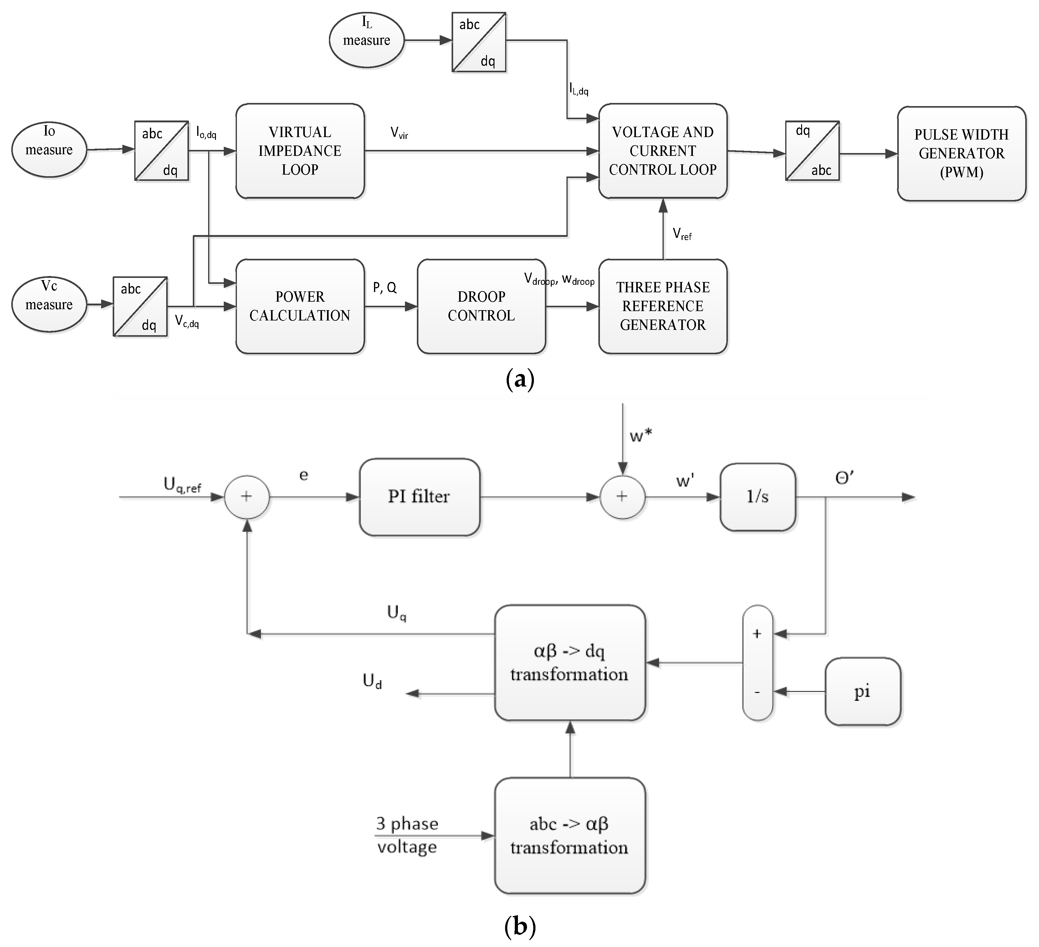
The droop control loop, implementing the proposed regulation method and containing the constraints of the optimization problem, is shown in Figure 4a. A Phase-Locked Loop (PLL) is used to remove disturbance signals and keep the system frequency stable at its reference values [5,36]. The structure of phase-locked loop is illustrated in the Figure 4b.
As shown in Figure 4a, the control signals are transferred to the control loops (Proportional Integral (PI) controllers) to generate the reference signals for the Pulse Width Modulator (PMW). The symmetrical optimum method is used to adjust the PI controller [37].
The process model transfer function is expressed as follows:
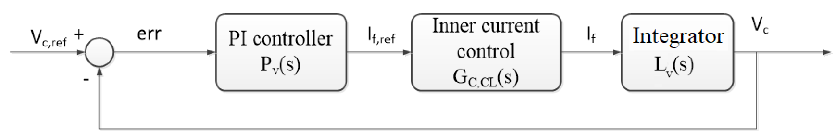
where KP is the proportional gain constant; is the switching frequency of the PWM; Ti is the integral time constant and σ is defined as the symmetrical distance between 1/Ti and 1/Te to crossover frequency fc. The recommended value for σ is between 2 and 4. By increasing σ, the system will have a better damping and higher phase margin, but its response will become slower [38]. The block diagram of the outer voltage PI controller is presented in Figure 5.
Figure 5 shows a PI controller Pv(s), an inner current control block GC,CL(s) and the integrator block Lv(s), whose transfer functions are:
where Cf is filter parameters.
The open loop Gv(s)OL and close loop Gv(s)CL transfer functions of the current controller are defined as it follows:
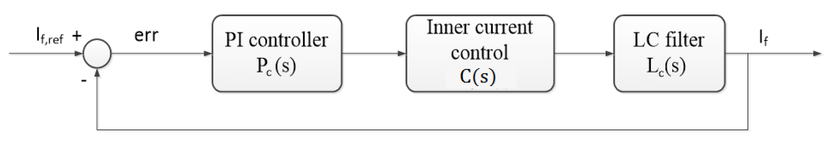
The block of the outer current PI controller is presented in Figure 6.
The transfer function of the current loop can be expressed as:
where Lf and Rf are the filter parameters and Tf is the system time constant.
The open Gc(s)OL and close loop Gc(s)CL transfer functions of the current controller are defined as it follows:
3. Case Study
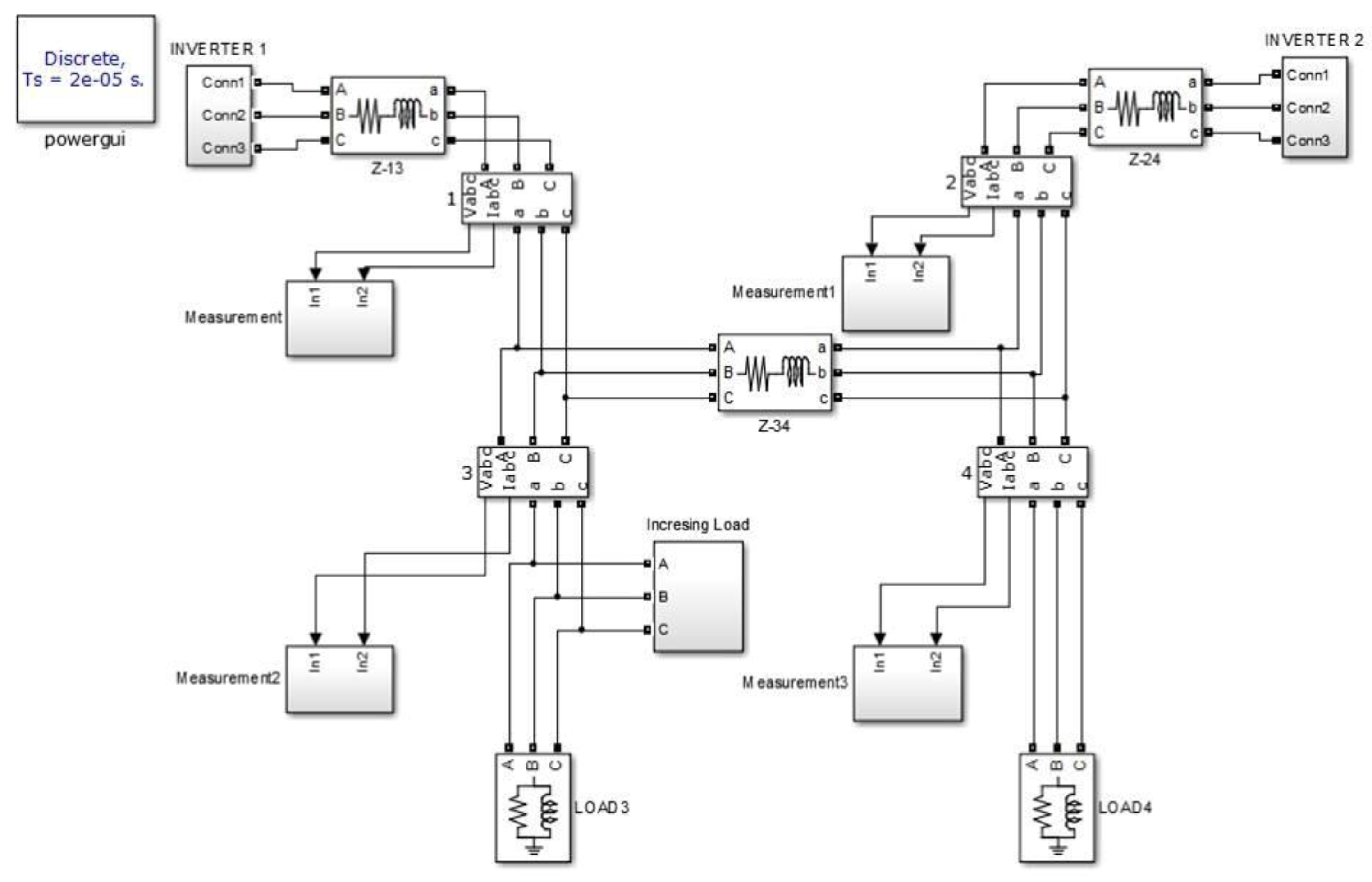
The effects of the proposed regulation method on the real power sharing between DGs are analyzed in a simple case study. The test microgrid in Figure 7 is based on the 4-bus test system issued by IEEE [39]. However, the parameters are modified to be more appropriate for the proposed problem. A system with two generators indicated as DG1 and DG2 and two loads, is considered. The electrical parameters of the microgrid are reported in Table 2.
The generator DG1 can provide real power in the range 0–0.3 pu, while DG2 can operate in the range 0–0.2 pu. The no load-frequency f0 is assumed the same for DG1 and DG2 and equal to 1.02 pu. The system frequency limits are set to fmin = 0.98 pu and fmax = 1.02 pu, meaning that the frequency must be within +/−1 Hz of 50 Hz.
In the considered case study, the droop coefficient KG1 of DG1 is varied for adjusting the output power of the generators. KG1max is assumed equal to 7.5, while the coefficient KG2 of DG2 is assumed invariable and equal to 5 in all the examined cases. The load at bus 4 is assumed equal to 0.1 pu while the load at bus 3 varies in the range from 0.1 pu to 0.37 pu with a step equal to +0.02 pu.
For testing the proposed method in different conditions, in the following, three scenarios are considered:
- Scenario 1, implementing the conventional droop control method
- Scenario 2, implementing the proposed optimized control method with KG1 selected optimally in the range [5–7.5]
- Scenario 3, implementing the proposed optimized control method with KG1 selected optimally in the range [6–7.5]
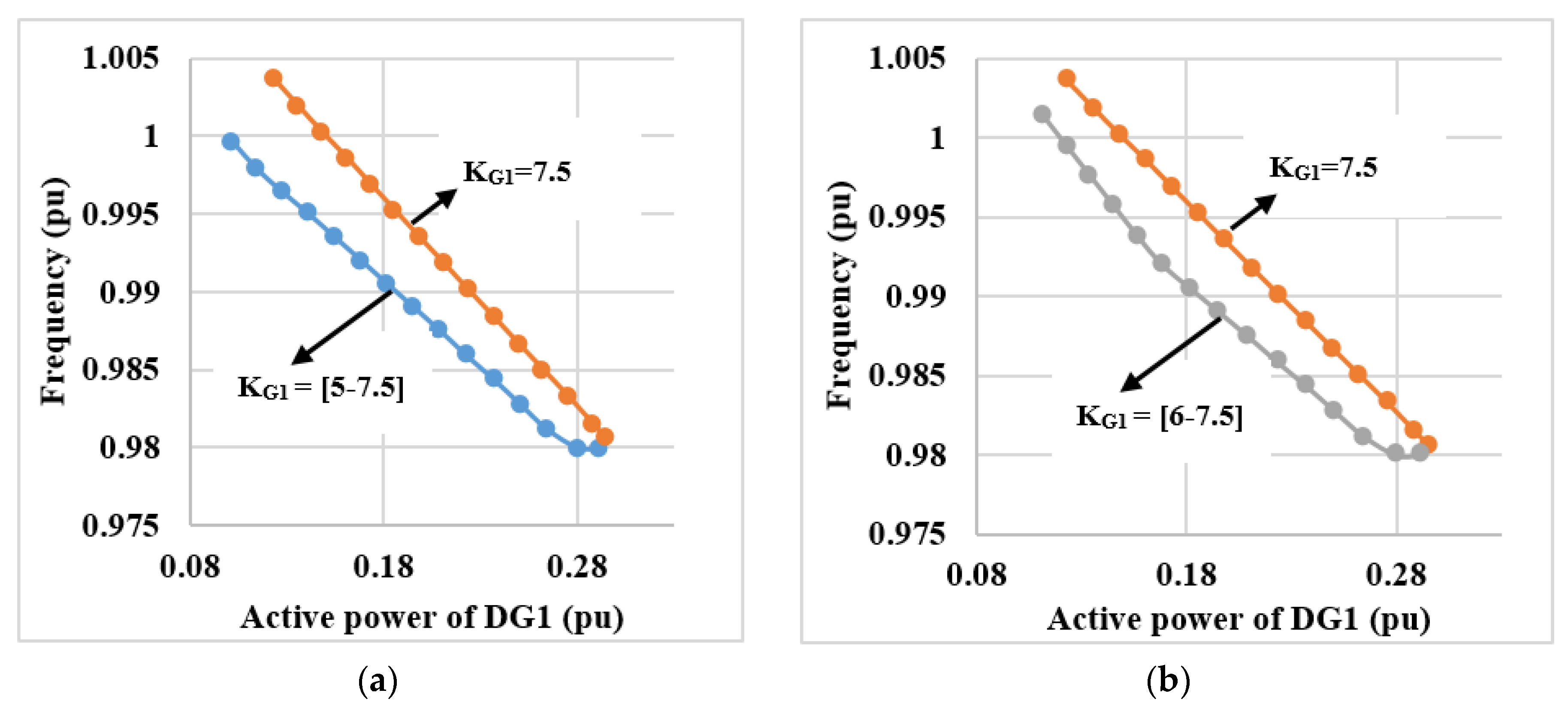
As shown in Section 2.2, the new droop curves of the generators are built by solving the OPF problem. Therefore, for the proposed example, there are two droop curves of DG1 constructed to reduce the power losses for the considered test microgrid. The first curve is built with KG1 selected optimally in the range [5–7.5] (Scenario 2) and is illustrated in Figure 8a. The second is built with KG1 in the range [6–7.5] (Scenario 3) and is shown in the Figure 8b. The conventional droop control curve (Scenario 1) is also represented in Figure 8 to show the improvements obtained with the proposed optimized control method.
The active power PG1 of the generator DG1, the power losses Ploss and the frequency f as function of KG1 are listed in Table 3.
4. Discussion
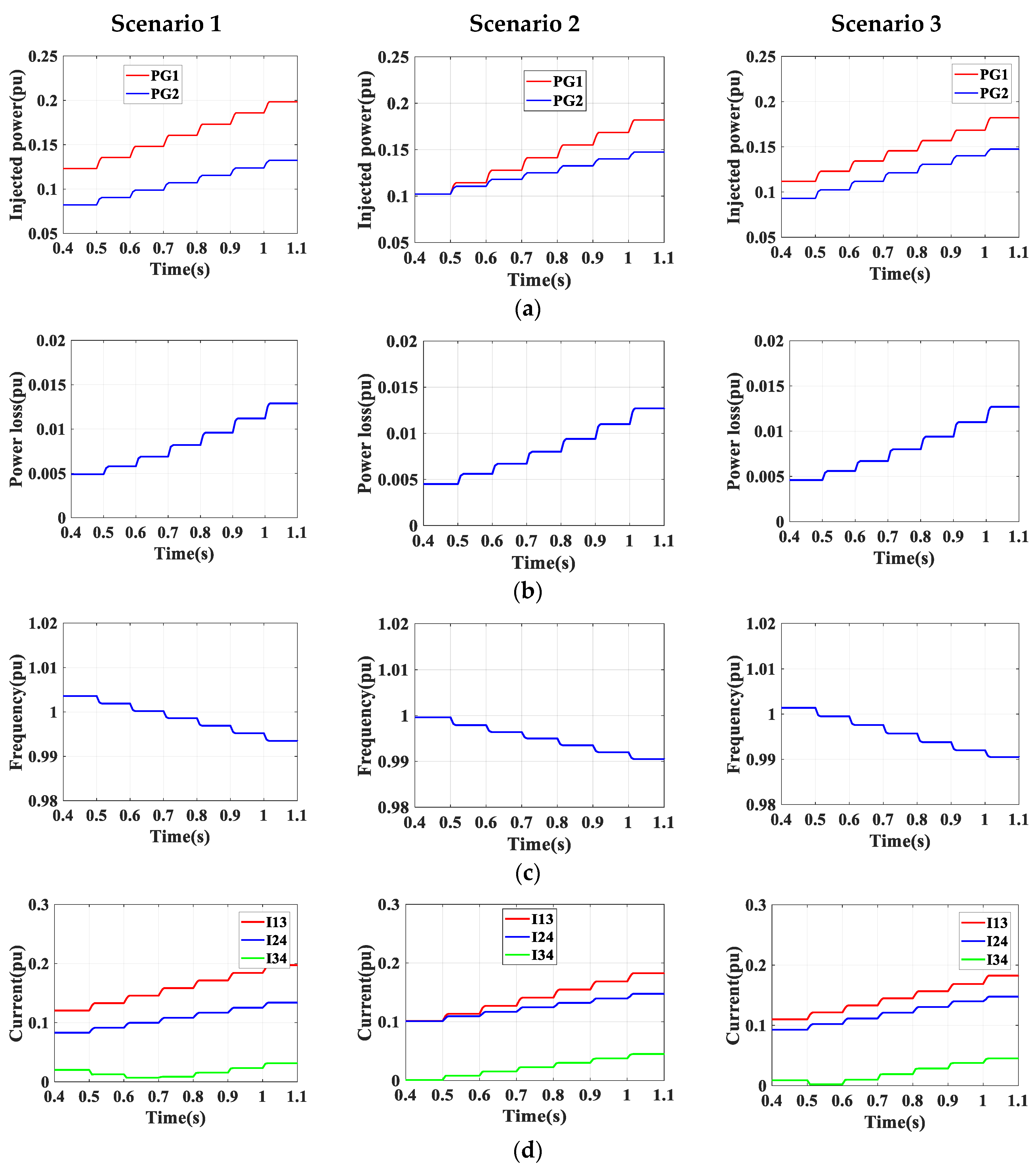
In the previous Figure 8, the underlying droop curve is a piecewise line that is composed by a set of 15 optimal operating points at different load demand conditions. With a different adjustment range of frequency coefficient, a different shape of the P–f curve is constructed. In order to figure out this set of optimized operating point, the program has to collect the information of power grid topology, load demands and power capacity of distributed generators, so for every specific microgrid, an unique droop control relation will be considered. In Table 2, it can be noticed that the scenario 2 with KG1 in the range [5–7.5] gives the best results in terms of power losses reduction with respect to scenario 1. Indeed, power losses are reduced of about 8% as compared to the conventional droop control method. The improvement is illustrated clearly at low power demand where the power sharing is needed to be adjusted for optimizing the microgrid’s operation.
The power losses in scenarios 2 and 3 are quite similar, but the variation of the adjustment range for the frequency coefficient leads to the variation of the power sharing between the generators and other parameters of islanded microgrid as shown in Figure 9.
Figure 9a shows the power sharing between the two DGs in the three scenarios. The wider range of droop coefficients, the greater adjustability of the generators, this explains why the power output of the distributed generators in the three cases is different. As a consequence, the frequency of the islanded microgrid is improved in each of scenario. With KG1 constant at 7.5 (scenario 1), the frequency fluctuates from 0.9918 pu to 1.0036 pu, while with KG1 in the range from 6 to 7.5, the frequency changes from 0.989 to 1.0014 and with KG1 varying in the range from 5 to 7.5, the frequency only changes from 0.989 to 0.9996. In all cases, the frequency stay within the constrained operating limits from 0.98 pu to 1.02 pu. Figure 9c shows that the frequency response is smooth: system frequency fluctuates within the imposed limits from 0.992 pu to 0.998 pu, without abnormal peaks or nadir. This trend demonstrates the stability of the proposed control method.
The values of the currents in the microgrid branches are shown in Figure 9d. The change in power sharing leads to the current flowing in transmission lines also changes. It observed that all values are smaller than the related limit Imaxbranch. From the results, it can be seen that the new proposed droop control method demonstrates its powerful efficiency compared to conventional droop method, the microgrid operates more effectively at every load variation. By this way, the frequency is kept within desired limits and the volumes are relieved for secondary and tertiary regulation which have to take over from primary control, if limited load-generators variations occur in the microgrid.
5. Conclusions
This work presented an improved droop regulation methodology for islanded microgrids. In the new methodology, solving an OPF problem, new feasible and optimized set points for distributed generators are found to minimize the microgrid operation losses and satisfy the grid and generators constraints. In this way, the frequency is kept within the desired limits and the energy volumes are relieved for secondary and tertiary regulation purposes. The GSO algorithm is selected to solve the OPF problem, for its ability of looking for global optimization and its fast convergence rate.
A case study was implemented for demonstrating the effectiveness of the proposed method in different loading conditions. And a Matlab/Simulink model was built for testing the operating characteristics of the system. The achieved results were compared to those obtained with the conventional droop regulation. It was shown that, when a load variation occurs, the proposed droop regulation adjusts the droop coefficients, minimizes the power losses, and maximizes the efficiency of power sharing between distributed generators.
In further works, the optimization procedure, that currently considers only the minimization of the microgrid’s power losses, will be modified in order to generate new droop regulation curves for larger systems, and to minimize also the microgrid’s operating cost. Moreover, the new regulation method will be applied to battery storage systems since they are currently showing their potential to enhance system stability in grid-connected and in islanded microgrids.
Author Contributions
Conceptualization and methodology, Q.T.T.T., E.R.S., G.Z., M.L.D.S.; Software, T.N.P., Q.T.T.T., M.L.D.S.; Validation, Q.T.T.T., T.N.P.; Formal Analysis, Q.T.T.T., T.N.P., E.R.S., M.L.D.S., G.Z.; Writing, Q.T.T.T., E.R.S., G.Z.; Supervision, E.R.S., M.L.D.S., G.Z.
Funding
This research was funded by Ministry of Foreign Affairs Italy, MAE.
Acknowledgments
The authors wish to thank the Italian Ministry of Foreign affairs and International Cooperation (MAECI), The Directorate General for the Promotion of the Italian Economic System (DGSP) for their support to the research activity within the frame of the Scientific cooperation Italy-Vietnam 2017-2019 (Project ‘Greening the power systems with solar power for Greenhouse gas emission reduction in Vietnam’).
Conflicts of Interest
The authors declare no conflict of interest.
Abbreviations and Nomenclature
| DG | Distributed generator | δi | Phase angles of the voltages at bus i |
| OPF | Optimal Power Flow | θij | Phase angle of Yij |
| GSO | Glow-worm Swarm Optimization | nbr | Number of branches connected to bus i |
| OF | Objective Function | P0i | Real power of the load in the operating point |
| ICT | Information and Communications Technology | Q0i | Reactive power of the load in the operating point |
| ACO | Ant Colony Optimization | α | Real power exponents |
| PSO | Particle Swarm Optimization | β | Reactive power exponents |
| PWM | Pulse Width Modulator | Yij | Admittance of the ij branch |
| PLL | Phase-Locked Loop | Kpf | Coefficient, ranging from 0 to 3.0 |
| PI | Proportional Integral | Kqf | Coefficient ranging from −2.0 to 0 |
| PGi | Real power generated of the i-th generator | ∆P | Real power deviation |
| QGi | Reactive power generated of the i-th generator | x(t) | Location of glow-worms in the search space at iteration t |
| KGi | Frequency droop coefficient of the i-th generator | l(t) | Value of luciferin at iteration t |
| Kdi | Voltage droop coefficient of the i-th generator | ρ | Luciferin decay constant |
| fx,i | Frequency at the i-th generator | γ | Enhancement constant |
| Vi | Output voltage at the i-th generator | Ni(t) | Set of neighborhood of glow-worm i at the t-th iteration |
| f0i | Frequency of the i-th generator at no load | s | Step-size |
| V0i | Voltage of the i-th generator at no load | rdi | Local decision range |
| KGmaxi | Maximum value of frequency droop coefficient of the i-th generator | KP | Proportional gain constant |
| PGmaxi | Rated power of i-th generator | fsw | The switching frequency of the PWM |
| nG | Number of generators in microgrid | Ti | Integral time constant |
| nd | Number of load buses | σ | Symmetrical distance |
| PLi | Real power demand of the i-th load | fc | Crossover frequency |
| Ibranchi | Current flowing in the i-th branch of the microgrid | Lv(s) | LC filter transfer function |
| Imaxbranchi | Ampacity of the i-th branch of the microgrid | Pv(s) | PI controller transfer function |
| nbranch | Number of transmission branches in the microgrid | GC,CL(s) | Inner current control transfer function |
| fmax | Frequency upper limit | Cf | Filter parameters |
| fmin | Frequency lower limit | Lf, Rf | Filter parameters |
| Pi | Injected power at bus i | Tf | System time constant |
| Ploss | Power losses of the microgrid | Gv(s)OL | Open loop transfer function |
| nbus | Number of buses of the microgrid | Gv(s)CL | Close loop transfer function |
| Vi | Voltages at buses i | ∆f | Frequency deviation |
References
- Hirase, Y.; Sugimoto, K.; Sakimoto, K.; Ise, T. Analysis of Resonance in Microgrids and Effects of System Frequency Stabilization Using a Virtual Synchronous Generator. IEEE J. Emerg. Sel. Top. Power Electron. 2016, 4, 1287–1298. [Google Scholar] [CrossRef]
- Karavas, C.; Kyriakarakos, G.; Arvanitis, K.G.; Papadakis, G. A multi-agent decentralized energy management system based on distributed intelligence for the design and control of autonomous polygeneration microgrids. Energy Convers. Manag. 2015, 103, 166–179. [Google Scholar] [CrossRef]
- Atia, R.; Yamada, N. Sizing and Analysis of Renewable Energy and Battery Systems in Residential Microgrids. IEEE Trans. Smart Grid 2016, 7, 1204–1213. [Google Scholar] [CrossRef]
- Han, H.; Hou, X.; Yang, J.; Wu, J.; Su, M.; Guerrero, J.M. Review of Power Sharing Control Strategies for Islanding Operation of AC Microgrids. IEEE Trans. Smart Grid 2016, 7, 200–215. [Google Scholar] [CrossRef] [Green Version]
- Chandorkar, M.C.; Divan, D.M.; Adapa, R. Control of parallel connected inverters in stand-alone AC supply systems. In Proceedings of the Conference Record of the 1991 IEEE Industry Applications Society Annual Meeting, Dearborn, MI, USA, 28 September–4 October 1991. [Google Scholar]
- Andrade, E.T.; Ribeiro, P.E.M.J.; Pinto, J.O.P.; Chen, C.L.; Lai, J.S.; Kees, N. A novel power calculation method for droop-control microgrid systems. In Proceedings of the 2012 Twenty-Seventh Annual IEEE Applied Power Electronics Conference and Exposition (APEC), Orlando, FL, USA, 5–9 February 2012. [Google Scholar]
- Klem, A.; Nehrir, M.H.; Dehghanpour, K. Frequency stabilization of an islanded microgrid using droop control and demand response. In Proceedings of the 2016 North American Power Symposium (NAPS), Denver, CO, USA, 18–20 September 2016. [Google Scholar]
- Ramezani, M.; Li, S. Voltage and frequency control of islanded microgrid based on combined direct current vector control and droop control. In Proceedings of the 2016 IEEE Power and Energy Society General Meeting (PESGM), Boston, MA, USA, 17–21 July 2016. [Google Scholar]
- Villa, A.; Belloni, F.; Chiumeo, R.; Gandolfi, C. Conventional and reverse droop control in islanded microgrid: Simulation and experimental test. In Proceedings of the 2016 International Symposium on Power Electronics, Electrical Drives, Automation and Motion (SPEEDAM), Anacapri, Italy, 22–24 June 2016. [Google Scholar]
- Hou, X.; Sun, Y.; Yuan, W.; Han, H.; Zhong, C.; Guerrero, M.J. Conventional P-ω/Q-V Droop Control in Highly Resistive Line of Low-Voltage Converter-Based AC Microgrid. Energies 2016, 9, 943. [Google Scholar] [CrossRef]
- Mariani, V.; Vasca, F.; Vásquez, J.C.; Guerrero, J.M. Model Order Reductions for Stability Analysis of Islanded Microgrids With Droop Control. IEEE Trans. Ind. Electron. 2015, 62, 4344–4354. [Google Scholar] [CrossRef] [Green Version]
- Brabandere, K.D.; Bolsens, B.; Keybus, J.V.d.; Woyte, A.; Driesen, J.; Belmans, R. A Voltage and Frequency Droop Control Method for Parallel Inverters. IEEE Trans. Power Electron. 2007, 22, 1107–1115. [Google Scholar] [CrossRef]
- Moazami Goodarzi, H.; Kazemi, H.M. A Novel Optimal Control Method for Islanded Microgrids Based on Droop Control Using the ICA-GA Algorithm. Energies 2017, 10, 485. [Google Scholar] [CrossRef]
- Elrayyah, A.; Cingoz, F.; Sozer, Y. Construction of Nonlinear Droop Relations to Optimize Islanded Microgrid Operation. IEEE Trans. Ind. Appl. 2015, 51, 3404–3413. [Google Scholar] [CrossRef]
- Sinha, M.; Dhople, S.; Johnson, B.; Ainsworth, N.; Dörfler, F. Nonlinear supersets to droop control. In Proceedings of the 2015 IEEE 16th Workshop on Control and Modeling for Power Electronics (COMPEL), Vancouver, BC, Canada, 12–15 July 2015. [Google Scholar]
- Ashabani, S.M.; Mohamed, Y.A.R.I. General Interface for Power Management of Micro-Grids Using Nonlinear Cooperative Droop Control. IEEE Trans. Power Syst. 2013, 28, 2929–2941. [Google Scholar] [CrossRef]
- Sun, Y.; Huang, W.; Wang, G.; Wenjun, W.; Wang, D.; Li, Z. Study of control strategy of DG based on nonlinear droop characteristic. In Proceedings of the 2012 China International Conference on Electricity Distribution, Shanghai, China, 10–14 September 2012. [Google Scholar]
- Krismanto, A.U.; Mithulananthan, N.; Lomi, A. Dynamic droop control in microgrid for stability enhancement considering RES variation. In Proceedings of the 2017 IEEE PES Innovative Smart Grid Technologies Conference Europe (ISGT-Europe), Torino, Italy, 26–29 September 2017. [Google Scholar]
- Hernandez-Aramburo, C.A.; Green, T.C.; Mugniot, N. Fuel consumption minimization of a microgrid. IEEE Trans. Ind. Appl. 2005, 41, 673–681. [Google Scholar] [CrossRef]
- Carniato, L.A.; Godoy, R.B.; Pinto, J.O.P.; Canesin, C.A.; Ribeiro, P.E.M.J. Dynamic adaptation of droop control curves for microgrid connected inverters with variable input power. In Proceedings of the 2013 Brazilian Power Electronics Conference, Gramado, Brazil, 27–31 October 2013. [Google Scholar]
- Arani, M.F.M.; Mohamed, Y.A.I. Dynamic Droop Control for Wind Turbines Participating in Primary Frequency Regulation in Microgrids. IEEE Trans. Smart Grid 2018. [Google Scholar] [CrossRef]
- Sanseverino, E.R.; Favuzza, S.; Silvestre, M.L.; Tran, Q.; Zizzo, G.; Pham, N.T.; Kieu, T.T.H. Improved primary regulation for minimum energy losses in islanded microgrids. In Proceedings of the 2017 IEEE PES Innovative Smart Grid Technologies Conference Europe (ISGT-Europe), Torino, Italy, 26–29 September 2017. [Google Scholar]
- Sanseverino, E.R.; Nguyen, N.Q.; Silvestre, M.L.D.; Zizzo, G.; Bosio, F.d.; Tran, Q.T.T. Frequency constrained optimal power flow based on glow-worm swarm optimization in islanded microgrids. In Proceedings of the 2015 AEIT International Annual Conference (AEIT), Naples, Italy, 14–16 October 2015. [Google Scholar]
- Buckspan, A.; Aho, J.; Fleming, P.; Jeong, Y.; Pao, L. Combining droop curve concepts with control systems for wind turbine active power control. In Proceedings of the 2012 IEEE Power Electronics and Machines in Wind Applications, Denver, CO, USA, 16–18 July 2012. [Google Scholar]
- Krpan, M.; Kuzle, I. Inertial and primary frequency response model of variable-speed wind turbines. J. Eng. 2017, 2017, 844–848. [Google Scholar] [CrossRef]
- Quang, N.N.; Sanseverino, E.R.; Silvestre, M.L.D.; Madonia, A.; Li, C.; Guerrero, J.M. Optimal power flow based on glow worm-swarm optimization for three-phase islanded microgrids. In Proceedings of the 2014 AEIT Annual Conference—From Research to Industry: The Need for a More Effective Technology Transfer (AEIT), Trieste, Italy, 18–19 September 2014. [Google Scholar]
- Kundur, P. Power System Stability and Control; McGraw-Hill: New York, NY, USA, 1994. [Google Scholar]
- Bibliography on load models for power flow and dynamic performance simulation. IEEE Trans. Power Syst. 1995, 10, 523–538. [CrossRef]
- Patel, M.J.; Patel, M.V.; Sorathiya, J. Real Power Loss Allocation Based on Circulating Current between Generators. Int. J. Emerg. Technol. Adv. Eng. 2013, 3, 232–239. [Google Scholar]
- Zhang, D.; Wang, F.F.; Burgos, R.; Boroyevich, D. Common-Mode Circulating Current Control of Paralleled Interleaved Three-Phase Two-Level Voltage-Source Converters With Discontinuous Space-Vector Modulation. IEEE Trans. Power Electron. 2011, 26, 3925–3935. [Google Scholar] [CrossRef]
- Li, M.; Zhang, X.; Zhao, W. A Novel Stability Improvement Strategy for a Multi-Inverter System in a Weak Grid Utilizing Dual-Mode Control. Energies 2018, 11, 2144. [Google Scholar] [CrossRef]
- Hosseinzadeh, M.; Salmasi, F.R. Power management of an isolated hybrid AC/DC micro-grid with fuzzy control of battery banks. IET Renew. Power Gener. 2015, 9, 484–493. [Google Scholar] [CrossRef]
- Guerrero, J.M.; Vasquez, J.C.; Matas, J.; Vicuna, L.G.d.; Castilla, M. Hierarchical Control of Droop-Controlled AC and DC Microgrids—A General Approach Toward Standardization. IEEE Trans. Ind. Electron. 2011, 58, 158–172. [Google Scholar] [CrossRef]
- Karegowda, A.G.; Prasad, M. A Survey of Applications of Glowworm Swarm Optimization Algorithm. In Proceedings of the International Conference on Computing and information Technology 2013 (IC2IT), Bangkok, Thailand, 9–10 May 2013. [Google Scholar]
- Krishnanand, D.G.; Kaipa, N. Glowworm Swarm Optimization: Theory, Algorithms, and Applications, 1st ed.; Springer: Norfolk, VA, USA, 2017; ISBN 978-331-951-594-6. [Google Scholar]
- Sheikh, A.; Youssef, T.; Mohammed, O. AC Microgrid Control Using Adaptive Synchronous Reference Frame PLL. In Proceedings of the 2017 Ninth Annual IEEE Green Technologies Conference (GreenTech), Denver, CO, USA, 29–31 March 2017. [Google Scholar]
- Barbosa, A.L.S.; Barros, P.R.; Acioli, G. Identification and PI controller redesign in symmetrical optimum based design. In Proceedings of the 2014 IEEE Conference on Control Applications (CCA), Juan Les Antibes, France, 8–10 October 2014. [Google Scholar]
- Bajracharya, C.; Molinas, M.; Suul, J.A.; Undeland, T.M. Understanding of tuning techniques of converter controllers for VSC-HVDC. In Proceedings of the Nordic Workshop on Power and Industrial Electronics Conference, Helsinki, Finland, 9–11 June 2008. [Google Scholar]
- IEEE Power and Eenergy Society, Analytic Methods for Power Systems Committee Distribution System Analysis Subcommittee Test Feeder Working Group. Available online: http://sites.ieee.org/pes-testfeeders/resources/ (accessed on 1 January 2018).
Figure 1.
Distributed generators connected to a load through three cable lines.

Figure 2.
Power sharing with conventional droop control method.

Figure 3.
Power sharing with new droop control method among two generating units.

Figure 4.
Simulation block diagram: (a) Block diagram of the control system of one inverter; (b) Structure of phase-locked loop (PLL).
Figure 4.
Simulation block diagram: (a) Block diagram of the control system of one inverter; (b) Structure of phase-locked loop (PLL).

Figure 5.
Block of the outer voltage PI controller.

Figure 6.
Block of the outer current PI controller.

Figure 7.
Test microgrid.

Figure 8.
P-f relation curves: (a) P-f relation of DG1 with KG1 selected optimally in the range [5–7.5]; (b) P-f relation of DG1 with KG1 selected optimally in the range [6–7.5].
Figure 8.
P-f relation curves: (a) P-f relation of DG1 with KG1 selected optimally in the range [5–7.5]; (b) P-f relation of DG1 with KG1 selected optimally in the range [6–7.5].

Figure 9.
Simulation results: (a) Real power of the distributed generators in the three scenarios; (b) Power losses of the microgrid in the three scenarios; (c) System frequency in the three scenarios; (d) Current of branches in the three scenarios.
Figure 9.
Simulation results: (a) Real power of the distributed generators in the three scenarios; (b) Power losses of the microgrid in the three scenarios; (c) System frequency in the three scenarios; (d) Current of branches in the three scenarios.


Table 1.
The advantages and disadvantages of droop control methods.
| Droop Control Methods | Conventional Droop Control | Non-Linear Droop Control | Dynamic Droop Control | Proposed Droop Control |
|---|---|---|---|---|
| References | [9,10,11] | [5,12,13,14,15,16,17] | [18,19,20,21] | |
| Simple | ✓ | - | - | ✓ |
| Easy to implement | ✓ | - | - | ✓ |
| Quick response | ✓ | - | - | ✓ |
| No communication signals between the inverters | ✓ | - | - | ✓ |
| Improved power sharing | - | ✓ | ✓ | ✓ |
| Improved stability | - | ✓ | ✓ | ✓ |
Table 2.
Electric parameters of the microgrid branches.
| Branch | R (pu) | X (pu) | R/X | Imaxbranch (pu) |
|---|---|---|---|---|
| 1–3 | 0.22229917 | 0.02873961 | 7.7 | 0.5396 |
| 2–4 | 0.22229917 | 0.02873961 | 7.7 | 0.5396 |
| 3–4 | 0.22229917 | 0.02873961 | 7.7 | 0.5396 |
Table 3.
New operating points of DG1 droop curve in the three scenarios.
| Scenario | Initial Load | Scenario 1 | Scenario 2 | Scenario 3 | ||||||||||
|---|---|---|---|---|---|---|---|---|---|---|---|---|---|---|
| PL3 | PL4 | KG1 | PG1 | Ploss | f | KG1 | PG1 | Ploss | f | KG1 | PG1 | Ploss | f | |
| 1 | 0.1 | 0.1 | 7.5 | 0.1233 | 0.0049 | 1.0036 | 5.01 | 0.1022 | 0.0045 | 0.9996 | 6.01 | 0.1118 | 0.0046 | 1.0014 |
| 2 | 0.12 | 0.1 | 7.5 | 0.1357 | 0.0058 | 1.0019 | 5.18 | 0.1144 | 0.0055 | 0.9979 | 6.00 | 0.123 | 0.0056 | 0.9995 |
| 3 | 0.14 | 0.1 | 7.5 | 0.1482 | 0.0069 | 1.0002 | 5.42 | 0.1279 | 0.0066 | 0.9964 | 6.00 | 0.1343 | 0.0067 | 0.9976 |
| 4 | 0.16 | 0.1 | 7.5 | 0.1607 | 0.0082 | 0.9986 | 5.66 | 0.1414 | 0.0079 | 0.995 | 5.99 | 0.1456 | 0.0080 | 0.9957 |
| 5 | 0.18 | 0.1 | 7.5 | 0.1732 | 0.0096 | 0.9969 | 5.85 | 0.1550 | 0.0093 | 0.9935 | 5.99 | 0.1569 | 0.0094 | 0.9938 |
| 6 | 0.2 | 0.1 | 7.5 | 0.1858 | 0.0112 | 0.9952 | 6.02 | 0.1686 | 0.0110 | 0.992 | 6.02 | 0.1685 | 0.0110 | 0.992 |
| 7 | 0.22 | 0.1 | 7.5 | 0.1985 | 0.0129 | 0.9935 | 6.17 | 0.1821 | 0.0127 | 0.9905 | 6.17 | 0.1821 | 0.0127 | 0.9905 |
| 8 | 0.24 | 0.1 | 7.5 | 0.2112 | 0.0147 | 0.9918 | 6.32 | 0.1958 | 0.0146 | 0.989 | 6.32 | 0.1958 | 0.0146 | 0.989 |
| 9 | 0.26 | 0.1 | 7.5 | 0.2239 | 0.0168 | 0.9901 | 6.44 | 0.2094 | 0.0167 | 0.9875 | 6.44 | 0.2094 | 0.0167 | 0.9875 |
| 10 | 0.28 | 0.1 | 7.5 | 0.2368 | 0.019 | 0.9884 | 6.54 | 0.2231 | 0.0189 | 0.9859 | 6.55 | 0.2232 | 0.0189 | 0.9859 |
| 11 | 0.3 | 0.1 | 7.5 | 0.2496 | 0.0214 | 0.9867 | 6.65 | 0.2369 | 0.0213 | 0.9844 | 6.65 | 0.2369 | 0.0213 | 0.9844 |
| 12 | 0.32 | 0.1 | 7.5 | 0.2626 | 0.0239 | 0.985 | 6.74 | 0.2507 | 0.0238 | 0.9828 | 6.74 | 0.2506 | 0.0238 | 0.9828 |
| 13 | 0.34 | 0.1 | 7.5 | 0.2755 | 0.0266 | 0.9833 | 6.82 | 0.2645 | 0.0265 | 0.9812 | 6.82 | 0.2645 | 0.0265 | 0.9812 |
| 14 | 0.36 | 0.1 | 7.5 | 0.2886 | 0.0295 | 0.9815 | 7.01 | 0.2805 | 0.0295 | 0.98 | 7.01 | 0.2803 | 0.0295 | 0.98 |
| 15 | 0.37 | 0.1 | 7.5 | 0.2952 | 0.0311 | 0.9806 | 7.29 | 0.2918 | 0.0311 | 0.98 | 7.29 | 0.2918 | 0.0311 | 0.98 |
© 2018 by the authors. Licensee MDPI, Basel, Switzerland. This article is an open access article distributed under the terms and conditions of the Creative Commons Attribution (CC BY) license (http://creativecommons.org/licenses/by/4.0/).
Share and Cite
MDPI and ACS Style
T.T Tran, Q.; Luisa Di Silvestre, M.; Riva Sanseverino, E.; Zizzo, G.; Pham, T.N. Driven Primary Regulation for Minimum Power Losses Operation in Islanded Microgrids. Energies 2018, 11, 2890. https://doi.org/10.3390/en11112890
AMA Style
T.T Tran Q, Luisa Di Silvestre M, Riva Sanseverino E, Zizzo G, Pham TN. Driven Primary Regulation for Minimum Power Losses Operation in Islanded Microgrids. Energies. 2018; 11(11):2890. https://doi.org/10.3390/en11112890
Chicago/Turabian StyleT.T Tran, Quynh, Maria Luisa Di Silvestre, Eleonora Riva Sanseverino, Gaetano Zizzo, and Thanh Nam Pham. 2018. "Driven Primary Regulation for Minimum Power Losses Operation in Islanded Microgrids" Energies 11, no. 11: 2890. https://doi.org/10.3390/en11112890
Note that from the first issue of 2016, this journal uses article numbers instead of page numbers. See further details here.