Sensorless PMSM Drive Implementation by Introduction of Maximum Efficiency Characteristics in Reference Current Generation

1
Energy Institute Hrvoje Požar, 10001 Zagreb, Croatia
2
Energy Agency of the Republic of Slovenia, 2000 Maribor, Slovenia
3
Power engineering institute, Faculty of Electrical Engineering and Computer Science; University of Maribor, 2000 Maribor, Slovenia
*
Author to whom correspondence should be addressed.
Energies 2019, 12(18), 3502; https://doi.org/10.3390/en12183502
Submission received: 30 July 2019
/
Revised: 4 September 2019
/
Accepted: 5 September 2019
/
Published: 11 September 2019
(This article belongs to the Special Issue Energy Efficiency in Electric Devices, Machines and Drives)
Abstract
:This paper presents the efficiency improvement in a speed closed-loop controlled permanent magnet synchronous machine (PMSM) sensorless drive. The drive efficiency can be improved by minimizing the inverter and the PMSM losses. These can be influenced by proper selection of DC-bus voltage and switching frequency of the inverter. The direct (d-) and quadrature (q-) axis current references generation methods, discussed in this paper, further improve the efficiency of the drive. Besides zero d-axis current reference control, the maximum torque per ampere (MTPA) characteristic is normally applied to generate the d- and q-axis current references in vector controlled PMSM drives. It assures control with maximum torque per unit of current but cannot assure maximum efficiency. In order to improve efficiency of the PMSM drive, this paper proposes the generation of d- and q-axis current references based on maximum efficiency (ME) characteristic. In the case study, the MTPA and ME characteristics are theoretically evaluated and determined experimentally by measurements on discussed PMSM drive. The obtained characteristics are applied for the d- and q-axis current references generation in the speed closed-loop vector controlled PMSM drive. The measured drive efficiency clearly shows that the use of ME characteristic instead of MTPA characteristic or zero d-axis current in the current references generation improves the efficiency of PMSM drive realizations with position sensor and without it—sensorless control.
1. Introduction
The energy savings during the entire exploitation time of an electric drive can be achieved only through a coordinated efficiency improvement of all components of the drive, including control algorithms. Nowadays, efficiency maximization is a normal design aspect for electric drives. Thus, more and more researchers are occupied with decreasing overall power losses of electric drives and simultaneously saving component and operational costs. In some applications, minimum loss is not only one of the design criteria, but is of paramount importance, e.g., in battery-powered road-vehicles [1,2] or even more importantly in autonomous aircrafts [3]. In such applications, even a small decrease of losses can have a significant impact on overall system performance in terms of ensuring adequate operating range. Due to its high efficiency, high power density and wide operating range of speed, the permanent magnet synchronous machine (PMSM) is used very often. By employment of a speed- or position-sensorless control, a more compact drive with less maintenance [4,5,6] can be obtained.
Besides designing a new machine, the efficiency of the drive can be improved by minimizing losses of the power inverter by proper selection of the DC-bus voltage and the switching frequency [7,8,9], and a proper control of the PMSM as well. Sensorless PMSM drive control algorithms vary in complexity and computational performance demanded by different target applications. The main difference between available sensorless control algorithms from the literature is that model-based methods [5,10,11,12,13] are more straightforward to implement but are not directly applicable at standstill, and therefore saliency-based methods [14,15,16] have been developed. Authors combine the aforementioned methods in various approaches [9,17,18,19,20], thus ensuring adequate sensorless performance from zero speed up to the field-weakening region.
In the case of vector controlled PMSM, a proper selection of the direct (d-) and quadrature (q-) axis current references can further improve drive efficiency. The simplest zero d-axis current reference control (idr = 0) is still employed in applications with surface mounted PMSMs [21], which exhibit similar values of d- and q-axis inductances. Although it is generally applicable, the maximum torque per ampere (MTPA) characteristic [10,15,19,20,21,22,23,24,25,26,27], which considers PMSM copper losses, is usually used for generation of current references in drives with interior PMSM, which exhibit different values of d- and q-axis inductances and thus produce a significant reluctance torque component in addition to the permanent magnet torque component. When MTPA is applied, the PMSM drive produces maximum torque per unit of stator current but cannot reach the maximum efficiency due to the neglected iron core losses. The maximum efficiency (ME) characteristic [21,23,24,25,26,27,28] considers copper losses as well as iron core losses of PMSM. When it is applied for generation of current references, the maximum efficiency of a PMSM drive can be achieved. The concept was first evaluated by Colby et al. [29] for a surface mounted PMSM. Later it was applied by Morimoto et al. [30] in control of an interior PMSM drive as well. More recently, Pohlenz et al. [23] and Cavallaro et al. [28] reported improved efficiencies by implementing ME in the control software. While applying ME, Hassan et al. [24] analyzed PMSM and inverter losses due to changed harmonic content. Ni et al. [21] developed an iron loss formula by introducing new coefficients. However, the needed detailed PMSM data might not always be available, as discussed later.
General forms of the MTPA characteristic and the ME characteristic are shown in Figure 1a, from where it is evident that ME characteristics require higher values of the negative d-axis current in comparison to the MTPA characteristics, and MTPA characteristics in turn require higher values of the negative d-axis current than the idr = 0 control. Figure 1b shows the stator current vector Is and its components Id and Iq, where |Is| denotes the length of Is.
In this paper, the origins of losses in a PMSM drive are introduced and evaluated in Section 2. The PMSM model is used to explain the differences between the MTPA and ME characteristics, and to obtain the equations which relate the ME characteristics to the stator currents Id and Iq in Section 3. Although the ME characteristics are usually derived in relation to the magnetizing currents Imd and Imq, the here presented equation (20) provides the optimal current Id for a given load torque by considering the ME characteristic-i.e., the copper and the iron losses of the PMSM. Furthermore, this paper focuses on the drive implementation from the control designer’s point of view, where detailed information of the PMSM is not available, contrarily to machine designer’s point of view, where all details of the PMSM are known [21]. Unfortunately, the aforementioned equations cannot be used directly in the control implementation because the needed iron core resistance parameter value Rc cannot be determined directly or to be modeled in form of a function. Therefore, this paper proposes an alternative, which is suitable for control design and applicable to all types of PMSM. There the ME characteristics are determined experimentally by measurements performed on the tested vector controlled PMSM drive. The existing control algorithm is extended by a current references generator, where the determined ME characteristics are applied to generate the d- and q-axis current references. The speed closed-loop vector control of PMSM, obtained in this way, is used to measure the efficiency of the entire drive. The control is realized with the position sensor and without it—sensorless control.
Moreover, in this work the ME characteristics are implemented in sensorless control for the first time and presented in Section 4. There the rotor speed and position are determined by nonlinear phase-locked loop (PLL) observer [9,31], whose inputs are calculated by the modified active flux method [32,33,34,35]. It is shown that the drive efficiency can be improved when ME characteristics are used to generate the d- and q-axis current references, which is true for the sensorless control as well as for the control realization with position sensor. In order to facilitate a direct comparison, the space vector modulation has been utilized without any advanced modulation techniques such as discussed in [36,37]. Section 5 then concludes the paper.
2. PMSM Drive Losses
A PMSM drive normally consists of the PMSM, power inverter, load, and the control system. The load is the element, which dictates the proper selection of the other PMSM drive elements. The energy conversion process inevitably includes losses, mostly in the power inverter and PMSM. These loss components substantially influence the drive efficiency. This paper focuses on the detailed research of PMSM losses, which are minimized in the speed closed-loop controlled PMSM drive by a proper generation of d- and q-axis current references.
The employed PMSM had surface mounted magnets and was rated for 400 V and 1.6 kW at 2250 rpm.
2.1. Power Losses in Power Inverter
The power losses in a power inverter consist of conduction or Ohm’s losses and switching losses. In this work they are minimized by proper selection of the DC-bus voltage, where the impact of dead times is minimized [5,8,9] and by proper selection of the switching frequency [7,24,36,37] as well. The proper values were determined experimentally by measurements performed on the tested PMSM drive.
In order to evaluate the impact of switching frequency on drive efficiency, a series of tests was performed, where the PMSM load was varied, while the switching frequency was set to 4, 6, and 9 kHz, respectively. Figure 2 presents the PMSM drive efficiency characteristics in dependence of the current vector length . Drive efficiencies vary because the inverter losses increase with the increase of switching frequency and simultaneously the PMSM losses decrease with the increase of switching frequency [38], and the drive efficiency represents their product. Figure 2 shows that the highest efficiency of this particular PMSM drive was obtained when the switching frequency of 6 kHz was employed. Thus, the aforementioned switching frequency value was used through all successive tests.
In addition to the switching frequency, the inverter’s DC-bus voltage influences the PMSM drive efficiency as well. When the desired inverter output voltage is much smaller than the DC-bus voltage, then the inverter output voltage pulses are unnecessarily narrow which increases switching losses. However, it is noted that the DC-bus voltage control is not possible if a diode rectifier is employed in the inverter. In order to evaluate the impact of DC-bus voltage on PMSM drive efficiency, a series of tests was performed, where the PMSM load was varied, while the rotor speed and DC-bus voltage were set to different values. The PMSM efficiency was not significantly affected by the change of DC-bus voltage. Thus, the significant variation of PMSM drive efficiency presented in Figure 3 was due to the inverter efficiency variation by the change of DC-bus voltage. The differences in efficiencies at low speeds were more expressed because the PMSM back-emf was smaller at low speeds. The implementation of variable DC-bus voltage could make sense in variable speed drives operating mostly at partial loads and in a broad range of speeds in applications where efficiency is crucial.
2.2. Power Losses in PMSM
The analysis of power losses in the PMSM is based on the two-axis steady-state PMSM model with lumped parameters, written in the d-q reference frame. The d-axis was aligned with the flux linkage vector due to the permanent magnets while the q-axis led for electrical π/2. The model is schematically shown in Figure 4.
The copper losses are considered by the stator resistance Rs while the iron core losses are accounted for by the iron core resistance Rc. In the steady-state model, written in the d-q reference frame, the indices d and q refer to the d- and q-axis, Ud and Uq are the stator voltages, Id and Iq are stator currents, Imd and Imq are the magnetizing currents, Icd and Icq are the iron core currents, Ld and Lq are the stator inductances, Ψmd is the flux linkage due to the permanent magnets, Te is the electromagnetic torque, ωe is the electrical rotor speed and pp is the number of pole pairs. Considering Figure 4, the voltage Equation (1) and the torque Equation (2) can be written:
where
The power losses in the PMSM Ploss,PMSM can be divided into controllable losses, which are the copper losses Ploss,Cu and the iron core losses Ploss,Fe, and uncontrollable losses, which are the mechanical and additional losses [28]. Neglecting the uncontrollable losses, (4) describes the PMSM losses.
Considering Figure 4 and Equations (1) to (4), Ploss,Cu and Ploss,Fe can be expressed by (5) and (6).
3. Improving Efficiency by Reference Current Generation
Assuming a given inverter and a given PMSM, the PMSM drive efficiency can be improved by minimizing inverter losses and PMSM losses. In addition to advanced modulation techniques [36,37], the inverter losses can be mostly influenced by the closed-loop control or a proper choice of DC-bus voltage and by an optimal choice of switching frequency [24]. The PMSM losses can be influenced by the voltage and current total harmonic distortion that depend on the switching frequency [7,24,38], and in the case of vector controlled PMSM by the generation of the d- and q-axis current references. The generation of current references is usually based idr = 0 or on the MTPA characteristic [10,15,19,20,21,22,23], which assures the maximum torque per unit of current but not the maximum efficiency of the entire drive [21,23]. The last can be achieved when the ME characteristic is applied for generation of the d- and q-axis current references.
3.1. Theoretical Background of the MTPA and ME Characteristics
Let us consider all parameters of the PMSM steady-state model, shown in Figure 4 and described by Equations (1) to (6), as constant. The starting point for derivation of the MTPA characteristic is the torque equation (Equation (2)) and the PMSM steady-state model shown in Figure 4, where the iron core resistance is neglected (Rc →∞). Consequently, according to Equation (3), Icd and Icq equal zero which leads to Id = Imd and Iq = Imq. Considering the angle of the stator current vector α, shown in Figure 1b, the relation between the d- and q-axis currents, that provides the maximum torque per unit of current, can be determined from Equation (2) by Equation (7), which yields Equation (8) [22].
Similarly, the ME characteristic describes the relation between the d- and q-axis current that provides the minimum of PMSM losses, which leads to the maximum efficiency of the PMSM drive. According to [24,28], the PMSM losses (Equation (4)) can be minimized for each combination of Te, and ωe. Considering Equation (2) in Equations (5) and (6), Equation (4) can be expressed as a function of Imd, Te, and ωe. In the case of steady-state operation, Te, and ωe are constants, which means that the PMSM power losses Ploss,PMSM (Equation (4)) can be described as a function of Imd. However, because Te (Equation (2)) depends on Imd and Imq, the PMSM power losses can be minimized by Equation (9), which yields Equation (10) [24] describing the ME characteristic.
3.2. Evaluation of the Impact of Rc on the ME Characteristic
A sensitivity analysis was performed in order to evaluate the impact of the iron core resistance Rc on the ME characteristic. The parameter Rc was varied while the other PMSM parameters presented in Table 1 remained constant. The theoretical derivation of obtaining the necessary measurable current Id for every corresponding combination of Iq and ωe is presented hereinafter with the assumption of constant PMSM model parameters in the given operating points.
The voltage equations derived from Figure 4 can be rewritten also in the form of Equation (11).
Considering Equation (3), the currents Imd and Imq can be expressed in terms of the measurable stator currents Id and Iq (Equation (12)). Note that it is essential for control implementation that measurable quantities (such as Id and Iq instead of Imd and Imq) are included in the algorithm.
Similarly, the currents Icd and Icq can be expressed in terms of Id and Iq (13).
Then the PMSM losses can be expressed in terms of Id and Iq as well (14).
If we consider Equation (15) in Equation (14), then Equation (16) is obtained.
The PMSM losses are minimized by Equation (17), yielding Equation (18).
By rearranging Equation (18) we obtain Equation (19) and consequently Equation (20) which provides the necessary current Id for every corresponding combination of Iq and ωe.
Figure 5 presents the obtained MTPA characteristic by Equation (8), and the obtained ME characteristics by Equation (20) at different values of rotor speed and different values of the iron core resistance Rc. Although, this may not be evident from Figure 5 and similarly to the MTPA characteristics, the ME characteristics are nonlinear. It is however evident from Figure 5 that the iron core resistance Rc plays a crucial role in shaping the ME characteristic. Unfortunately, in practice its value changes depending on operating conditions and it cannot be determined directly or to be given in form of a function.
Therefore, the authors have turned to an implicit but general approach for determination of the ME characteristic based on experiments, which is described hereinafter. The determined ME characteristics are then used to improve the efficiency of the PMSM drive in sensorless control as well as for the control realization with position sensor. The approach proposed here is novel, and can easily be adopted by control designers when of-the-shelf (or unknown) PMSMs are employed—contrarily to methods based, e.g., on finite element analyses which depend on detailed information about the employed geometry and materials in the PMSM.
3.3. Experimental Determination of ME Characteristics
The ME characteristics derived theoretically in the previous subsections are based on the steady-state PMSM model with constant parameters. With the aim to improve the PMSM drive efficiency and to evaluate the previously presented results, the characteristics were determined also by measurements performed on the PMSM drive, schematically shown in Figure 6. The presented approach includes all effects that are also present during real drive operation in the ME characteristics, these being effects of magnetic nonlinearities, saturation, cross-coupling, end-winding leakage, permanent magnets and slotting, converter nonlinearities and dead times in transistor switching. The PMSM was torque controlled and fed by the inverter. This means that during all tests the d- and q-axis currents were close-loop controlled, following their references set to different constant values. The vector control of PMSM was realized on the control system dSPACE PPC 1103. The rotor speed was closed-loop controlled by an active load IM. The input and output power of the inverter and PMSM, and their efficiencies, were measured by the power analyzers NORMA I (Norma D5255M) and NORMA II (Norma D6100), as shown Figure 6. The equal equipment was used throughout all successive tests, thus enabling a direct and comprehensive comparison of the PMSM drive efficiency operating in closed-loop control with or without the position sensor.
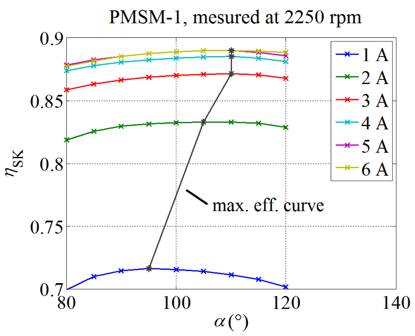
The ME characteristics were determined by changing the length and angle of the stator current vector at different values of the rotor speed. In individual steady-states, based on the measurements of voltages, currents, powers, torque and speed, the efficiencies are determined. A three-dimensional matrix of measurement results was generated, which includes length and angle of the stator current vector as well as the rotation speed. The experimentally obtained drive efficiency curves at 2250 rpm in dependence of the length and angle of the stator current vector are shown in Figure 7. The ME characteristic at 2250 rpm was then determined by connecting the points of maximum efficiencies of respective efficiency curves (black line). The determined ME characteristics at different rotor speeds are then shown in Figure 8, where they are presented in dependence of d- and q-axis currents. From Figure 8 it is evident that if we want to control the drive with maximum efficiency, the d-axis current component has to be increased by increase of the rotor speed, which is also known as flux-weakening. Unfortunately, due to hardware limitations, only currents of up to 6 A could be achieved during the experiments.
4. Results and Discussion
This section shows how the employment of the previously experimentally determined ME characteristics influences the efficiency of the discussed speed closed-loop controlled PMSM drive, when it is used to generate the d- and q-axis current references. The rotor position and speed required for the control realization are obtained in two different ways: firstly, by using sensors and secondly, by the sensorless control. In the last case, the measured PMSM currents and DC-bus voltage are used together with the PMSM dynamic model to calculate the rotor position and speed. The active flux based sensorless control method is applied. The active flux ΨAF is defined as a hypothetical flux, which multiplied by the instantaneous q-axis current iq produces the measured instantaneous electro-magnetic torque te [32,33,34,35]. Consequently, the effects which are neglected in the PMSM model are thus considered by employment of ΨAF.
The active flux concept uses the flux linkage vector estimates αβu and αβi obtained by the voltage (index u) and current models (index i) (Equation (22)), written in the α-β reference frame [32]. The difference between both estimates gives the compensation voltage uk, which is added in the voltage model to eliminate the DC-offset and other errors in measured stator currents, variation of stator resistance, and integrator drifts in the calculation procedure.
Considering zero initial conditions, the required estimates of the electrical rotor speed and position are calculated by the nonlinear PLL-observer (Equation (23)) [31], where ε represents the error signal; k1 and k2 represent the observer gains.
Thus, in the case of sensorless control, the estimates and (Equation (23)) are used instead measured speed and position in the control algorithm, enabling closed loop-speed control without mechanical speed sensor.
Figure 9 shows the schematic presentation of the speed closed-loop control realizations with sensors (position and speed) and without them. These control realizations are applied in the experimental set-up, shown in Figure 6, which is used to measure drive efficiencies in cases when idr = 0, MTPA and ME characteristics, respectively. These characteristics (MTPA or ME) are used to determine the d- and q-axis current references idr and iqr.
Figure 10 shows the measured PMSM drive efficiencies (ηALL) at the rated speed of 2250 rpm and different loads in the case when idr = 0 and in the cases when idr and iqr are determined with the MTPA and ME characteristics, respectively. The results are given for the control realization with position and speed sensors and for the sensorless control. They are completed by the presentation of differences between different measured efficiency curves.
The presented results clearly show that the lowest efficiencies are achieved when idr = 0. The drive efficiency is improved when the MTPA characteristic is used for the generation of idr and iqr. When it is replaced with the ME characteristic, the drive efficiency is further improved. Similar findings have been reported in [21,23,28] for an IPMSM drive with position sensor. The efficiency improvements decrease with the increase of the load torque (Tm). This is true for the control realization with the position and speed sensors as well as for the sensorless control realization.
5. Conclusions
This paper presents a way of improving the PMSM drive efficiency, where the more usual idr = 0 and MTPA characteristic for generation of reference current in vector controlled PMSM drives are compared with the proposed ME characteristic. There, both copper and iron core losses of the PMSM are considered. The equations which relate the ME characteristics to the measurable stator currents Id and Iq which are needed by control designers (instead to the magnetizing currents Imd and Imq) are derived, and consequently the equation which provides the optimal current Id for a given load torque by considering the ME characteristic is obtained for the first time. The problem of adequately determining the iron core resistance parameter value Rc is effectively mitigated by employing experimentally determined ME characteristics on the real PMSM drive system. Differences between the MTPA and ME characteristics are detailed; they are used in speed closed-loop vector control realizations with position and speed sensors and without them. The ME characteristic is implemented in sensorless control for the first time, where a nonlinear PLL observer is applied. Its inputs are calculated by the modified active flux method. The work clearly demonstrates that the use of ME characteristic instead of MTPA characteristic or idr = 0 in the current references generation improves the efficiency of PMSM drive realizations with position and speed sensors and without them—sensorless control.
This particular comparative case study showed that choosing an adequate switching frequency might improve the drive efficiency by 1.5–5.0%. At small load and speed values where the voltage value is small as well, an adequate DC-bus voltage control may improve the drive efficiency up to 30%. Ultimately, this particular PMSM drive efficiency was improved by 0.1–0.5% when the proposed ME was implemented in comparison to the MTPA, and by 1.0–2.0% in comparison to idr = 0, respectively. Therefore, it should be preferred that the PMSM drive control solutions proposed here are implemented in applications where efficiency is crucial. Moreover, the ME implementation can cut down the annual energy consumption of the studied drive by up to approximately 130 kWh, depending on the load and control case presented in Figure 11. This fact certainly cannot be neglected, since its implementation requires merely the modification of a few lines of code in the control realization.
Author Contributions
Ž.P. performed derivations, experimental work and analyses. T.M. and M.B. prepared the final form of the paper, including editing of the text, equations and figures. G.Š. prepared the experiments and coordinated the research work and paper preparation.
Funding
This work was supported by the Slovenian Research Agency [grant numbers J2-1742, P2-0115].
Conflicts of Interest
The authors declare no conflict of interest.
References
- Yilmaz, M. Limitations/capabilities of electric machine technologies and modeling approaches for electric motor design and analysis in plug-in electric vehicle applications. Renew. Sustain. Energy Rev. 2015, 52, 80–99. [Google Scholar] [CrossRef]
- Wang, E.; Guo, D.; Yang, F. System design and energetic characterization of a four-wheel-driven series-parallel hybrid electric powertrain for heavy-duty applications. Energy Convers. Manag. 2015, 106, 1264–1275. [Google Scholar] [CrossRef]
- Gao, X.Z.; Houn, Z.X.; Guo, Z.; Chen, X.Q. Reviews of methods to extract and store energy for solar-powered aircraft. Renew. Sustain. Energy Rev. 2015, 44, 96–108. [Google Scholar]
- Daili, Y.; Gaubert, J.P.; Rahmani, L. Implementation of a new maximum power point tracking control strategy for small wind energy conversion systems without mechanical sensors. Energy Convers. Manag. 2015, 97, 298–306. [Google Scholar] [CrossRef]
- Finch, J.W.; Giaouris, D. Controlled AC electrical drives. IEEE Trans. Ind. Electron. 2008, 55, 481–491. [Google Scholar] [CrossRef]
- Chaoui, H.; Khayamy, M.; Okoye, O. MTPA based operation point speed tracking for PMSM drives without explicit current regulation. Electr. Power Syst. Res. 2017, 151, 125–135. [Google Scholar] [CrossRef]
- Ancuti, R.; Boldea, I.; Andreescu, G.D. Sensorless V/f control of high-speed surface permanent magnet synchronous motor drives with two novel stabilising loops for fast dynamics and robustness. IET Electr. Power Appl. 2010, 4, 149–157. [Google Scholar] [CrossRef]
- Krüner, S.; Hackl, C.M. Experimental Identification of the Optimal Current Vectors for a Permanent-Magnet Synchronous Machine in Wave Energy Converters. Energies 2019, 12, 862. [Google Scholar] [CrossRef]
- Wang, G.; Yang, R.; Xu, D. DSP-based control of sensorless IPMSM drives for wide-speed-range operation. IEEE Trans. Ind. Electron. 2013, 60, 720–727. [Google Scholar] [CrossRef]
- Chi, W.C.; Cheng, M.Y. Implementation of a sliding-mode-based position sensorless drive for high-speed micro permanent-magnet synchronous motors. ISA Trans. 2014, 53, 444–453. [Google Scholar] [CrossRef]
- Toman, M.; Dolinar, D.; Štumberger, G. Sensorless control of the permanent magnet synchronous motor. Electrotech. Rev. 2004, 71, 277–282. [Google Scholar]
- Kung, Y.S.; Thanh, N.P.; Wang, M.S. Design and simulation of a sensorless permanent magnet synchronous motor drive with microprocessor-based PI controller and dedicated hardware EKF estimator. Appl. Math. Model. 2015, 39, 5816–5827. [Google Scholar] [CrossRef]
- Lin, S.; Zhang, W. An adaptive sliding-mode observer with a tangent function-based PLL structure for position sensorless PMSM drives. Electr. Power Energy Syst. 2017, 88, 63–74. [Google Scholar] [CrossRef]
- Rostami, A.; Asaei, B. A novel method for estimating the initial rotor position of PM motors without the position sensor. Energy Convers. Manag. 2009, 50, 1879–1883. [Google Scholar] [CrossRef]
- Zhu, Z.Q.; Gong, L.M. Investigation of effectiveness of sensorless operation in carrier-signal-injection-based sensorless-control methods. IEEE Trans. Ind. Electron. 2011, 58, 3431–3439. [Google Scholar] [CrossRef]
- Wu, X.; Huang, S.; Liu, P.; Wu, T.; He, Y.; Zhang, X.; Chen, K.; Wu, Q. A reliable initial rotor position estimation method for sensorless control of interior permanent magnet synchronous motors. ISA Trans. 2019, in press. [Google Scholar] [CrossRef] [PubMed]
- Song, Z.; Hou, Z.; Jiang, C.; Wei, X. Sensorless control of surface permanent magnet synchronous motor using a new method. Energy Convers. Manag. 2006, 47, 2451–2460. [Google Scholar] [CrossRef]
- Omrane, I.; Etien, E.; Dib, W.; Bachelier, O. Modeling and simulation of soft sensor design for real-time speed and position estimation of PMSM. ISA Trans. 2015, 57, 329–339. [Google Scholar] [CrossRef] [PubMed]
- Foo, G.; Rahman, M.F. Sensorless sliding-mode MTPA control of an IPM synchronous motor drive using a sliding-mode observer and HF signal injection. IEEE Trans. Ind. Electron. 2010, 57, 1270–1278. [Google Scholar] [CrossRef]
- Chen, S.Y.; Luo, Y.; Pi, Y.G. PMSM sensorless control with separate control strategiesand smooth switch from low speed to high speed. ISA Trans. 2015, 58, 650–658. [Google Scholar] [CrossRef] [PubMed]
- Ni, R.; Xu, D.; Wang, G.; Ding, L.; Zhang, G.; Qu, L. Maximum efficiency per ampere control of permanent-magnet synchronous machines. IEEE Trans. Ind. Electron. 2015, 62, 2135–2143. [Google Scholar] [CrossRef]
- Pan, C.T.; Sue, S.M. A linear maximum torque per ampere control for IPMSM drives over full-speed range. IEEE Trans. Energy Convers. 2005, 20, 359–366. [Google Scholar] [CrossRef]
- Pohlenz, D.; Böcker, J. Efficiency improvement of an IPMSM using maximum efficiency operating strategy. In Proceedings of the 14th International Power Electronics and Motion Control Conference (EPE/PEMC), Ohrid, Macedonia, 6–8 September 2010; pp. T5-15–T5-19. [Google Scholar]
- Hassan, W.; Wang, B. Efficiency optimization of PMSM based drive system. In Proceedings of the 7th International Power Electronics and Motion Control Conference (IPEMC), Harbin, China, 2–5 June 2012; pp. 1027–1033. [Google Scholar]
- Wang, M.S.; Hsieh, M.F.; Lin, H.Y. Operational Improvement of Interior Permanent Magnet Synchronous Motor Using Fuzzy Field-Weakening Control. Electronics 2018, 7, 452. [Google Scholar] [CrossRef]
- Yu, L.; Zhang, Y.; Huang, W. Accurate and Efficient Torque Control of an Interior Permanent Magnet Synchronous Motor in Electric Vehicles Based on Hall-Effect Sensors. Energies 2017, 10, 410. [Google Scholar] [CrossRef]
- Li, H.; Gao, J.; Huang, S.; Fan, P. A Novel Optimal Current Trajectory Control Strategy of IPMSM Considering the Cross Saturation Effects. Energies 2017, 10, 1460. [Google Scholar] [CrossRef]
- Cavallaro, C.; Di Tommaso, A.O.; Miceli, R.; Raciti, A.; Galluzzo, G.R.; Trapanese, M. Efficiency enhancement of permanent-magnet synchronous motor drives by online loss minimization approaches. IEEE Trans. Ind. Electron. 2005, 52, 1153–1160. [Google Scholar] [CrossRef]
- Colby, R.S.; Novotny, D.W. Efficient operation of surface-mounted PM synchronous motors. IEEE Trans. Ind. Appl. 1987, IA-23, 1048–1054. [Google Scholar] [CrossRef]
- Morimoto, S.; Tong, Y.; Takeda, Y.; Hirasa, T. Loss minimization control of permanent magnet synchronous motor drives. IEEE Trans. Ind. Electron. 1994, 41, 511–517. [Google Scholar] [CrossRef]
- Harnefors, L.; Nee, H.P. A general algorithm for speed and position estimation of AC motors. IEEE Trans. Ind. Electron. 2000, 47, 77–83. [Google Scholar] [CrossRef]
- Boldea, I.; Paicu, M.C.; Andreescu, G.D. Active flux concept for motion-sensorless unified AC drives. IEEE Trans. Power Electron. 2008, 23, 2612–2618. [Google Scholar] [CrossRef]
- Boldea, I.; Paicu, M.C.; Andreescu, G.D.; Blaabjerg, F. Active flux” orientation vector sensorless control of IPMSM. In Proceedings of the 11th International Conference on Optimization of Electrical and Electronic Equipment (OPTIM), Brasov, Romania, 22–24 May 2008; pp. 161–168. [Google Scholar]
- Boldea, I.; Paicu, M.C.; Andreescu, G.D.; Blaabjerg, F. “Active Flux” DTFC-SVM sensorless control of IPMSM. IEEE Trans. Energy Convers. 2009, 24, 314–322. [Google Scholar] [CrossRef]
- Chen, J.; Chen, S.; Wu, X.; Tan, G.; Hao, J. A Super-Twisting Sliding-Mode Stator Flux Observer for Sensorless Direct Torque and Flux Control of IPMSM. Energies 2019, 12, 2564. [Google Scholar] [CrossRef]
- Di Piazza, M.C.; Pucci, M. Techniques for efficiency improvement in PWM motor drives. Electr. Power Syst. Res. 2016, 136, 270–280. [Google Scholar]
- Ghaeb, J.A.; Smadi, M.A.; Ababneh, M. Progressive decrement PWM algorithm for minimum mean square error inverter output voltage. Energy Convers. Manag. 2011, 52, 3309–3318. [Google Scholar] [CrossRef]
- Marčič, T.; Štumberger, G.; Hadžiselimović, M.; Zagradišnik, I. The impact of modulation frequency on losses, current harmonic distortion and motor temperature in an induction motor drive. Electrotech. Rev. 2006, 73, 125–130. [Google Scholar]
Figure 1.
Maximum torque per ampere (MTPA) and maximum efficiency (ME) characteristics (a) and stator current vector in α-β and d-q reference frame (b).
Figure 1.
Maximum torque per ampere (MTPA) and maximum efficiency (ME) characteristics (a) and stator current vector in α-β and d-q reference frame (b).

Figure 2.
Measured efficiency characteristics of the permanent magnet synchronous machine (PMSM) drive at different switching frequencies.
Figure 2.
Measured efficiency characteristics of the permanent magnet synchronous machine (PMSM) drive at different switching frequencies.

Figure 3.
Measured efficiency characteristics of the PMSM drive at different rotor speed and different DC-bus voltage.
Figure 3.
Measured efficiency characteristics of the PMSM drive at different rotor speed and different DC-bus voltage.

Figure 4.
Applied steady-state model of PMSM in d-q reference frame.

Figure 5.
Calculated MTPA and ME characteristics at different rotor speeds and different constant values of the iron core resistance Rc.
Figure 5.
Calculated MTPA and ME characteristics at different rotor speeds and different constant values of the iron core resistance Rc.

Figure 6.
Experimental set-up—schematic presentation.

Figure 7.
ME characteristic at 2250 rpm in dependence of the length and angle of the stator current vector.
Figure 7.
ME characteristic at 2250 rpm in dependence of the length and angle of the stator current vector.

Figure 8.
Experimentally determined ME characteristics.

Figure 9.
Schematic presentation of the applied speed closed-loop control.

Figure 10.
Measured efficiencies of the speed closed-loop controlled PMSM drive and their differences for the control realization with the mechanical sensor and for the sensorless control in the cases when idr and iqr are determined with MTPA and ME characteristics and in the case when idr = 0.
Figure 10.
Measured efficiencies of the speed closed-loop controlled PMSM drive and their differences for the control realization with the mechanical sensor and for the sensorless control in the cases when idr and iqr are determined with MTPA and ME characteristics and in the case when idr = 0.

Figure 11.
Annual energy savings achieved by different methods of reference current generation in the speed closed-loop controlled PMSM drive for the realization with the mechanical sensor and for the sensorless control.
Figure 11.
Annual energy savings achieved by different methods of reference current generation in the speed closed-loop controlled PMSM drive for the realization with the mechanical sensor and for the sensorless control.


Table 1.
Permanent magnet synchronous machine PMSM parameters.
| Parameter | Value |
|---|---|
| pp | 5 |
| Rs (Ω) | 1.15 |
| ψmd (Vs) | 0.2415 |
| Ld (H) | 0.02654 |
| Lq (H) | 0.02865 |
© 2019 by the authors. Licensee MDPI, Basel, Switzerland. This article is an open access article distributed under the terms and conditions of the Creative Commons Attribution (CC BY) license (http://creativecommons.org/licenses/by/4.0/).
Share and Cite
MDPI and ACS Style
Plantić, Ž.; Marčič, T.; Beković, M.; Štumberger, G. Sensorless PMSM Drive Implementation by Introduction of Maximum Efficiency Characteristics in Reference Current Generation. Energies 2019, 12, 3502. https://doi.org/10.3390/en12183502
AMA Style
Plantić Ž, Marčič T, Beković M, Štumberger G. Sensorless PMSM Drive Implementation by Introduction of Maximum Efficiency Characteristics in Reference Current Generation. Energies. 2019; 12(18):3502. https://doi.org/10.3390/en12183502
Chicago/Turabian StylePlantić, Željko, Tine Marčič, Miloš Beković, and Gorazd Štumberger. 2019. "Sensorless PMSM Drive Implementation by Introduction of Maximum Efficiency Characteristics in Reference Current Generation" Energies 12, no. 18: 3502. https://doi.org/10.3390/en12183502
Note that from the first issue of 2016, this journal uses article numbers instead of page numbers. See further details here.