Article

Gas Turbine Cycle with External Combustion Chamber for Prosumer and Distributed Energy Systems

1
Faculty of Mechanical Engineering, Gdansk University of Technology, Gabriela Narutowicza Street 11/12, 80-233 Gdansk, Poland
2
Department of Organization and Production Engineering, Warsaw University of Life Sciences, Nowoursynowska Street 164, 02-787 Warsaw, Poland
3
Department of Production Management, Bialystok University of Technology, Wiejska Street 45A, 15-351 Bialystok, Poland
*
Authors to whom correspondence should be addressed.
Energies 2019, 12(18), 3501; https://doi.org/10.3390/en12183501
Submission received: 16 July 2019 / Revised: 7 September 2019 / Accepted: 10 September 2019 / Published: 11 September 2019
(This article belongs to the Special Issue Small-Scale Energy Systems with Gas Turbines and Heat Pumps)

Abstract

:
The use of various biofuels, usually of relatively small Lower Heating Value (LHV), affects the gas turbine efficiency. The present paper shows that applying the proposed air by-pass system of the combustor at the turbine exit causes tan increase of efficiency of the turbine cycle increased by a few points. This solution appears very promising also in combined gas/steam turbine power plants. The comparison of a turbine set operating according to an open cycle with partial bypassing of external combustion chamber at the turbine exit (a new solution) and, for comparison, a turbine set operating according to an open cycle with a regenerator. The calculations were carried out for different fuels: gas from biomass gasification (LHV = 4.4 MJ/kg), biogas (LHV = 17.5 MJ/kg) and methane (LHV = 50 MJ/kg). It is demonstrated that analyzed solution enables construction of several kW power microturbines that might be used on a local scale. Such turbines, operated by prosumer’s type of organizations may change the efficiency of electricity generation on a country-wide scale evidently contributing to the sustainability of power generation, as well as the economy as a whole.

1. Introduction

An increase in the demand for energy and its carriers, as well as the growing legal requirements in the aspect of harmful emissions cause [1,2,3] the necessity to continuously increase the share of energy from renewable sources [4,5,6]. In addition to energy from water, wind or solar radiation, biomass is the most commonly used source of renewable fuel [7,8,9]. Its importance as an inexpensive and renewable source of energy grows particularly when it is produced from agricultural and forestry residues [10,11]. The use of by-products or residues of the agri-food industry for biogas or biofuel production is frequently observed. The growing level of public awareness together with the tightening of legal requirements in environmental protection issues add dynamics to the increase in the level of attractiveness of activities and technologies leading to the reduction of adverse human impact on the ecosystem [12,13,14]. The sustainability of biomass derived energetics based on distributed electricity generation can be assessed by means of life cycle assessment (LCA) methodology, as well as the direct approach offered by [15,16,17]. During managing of the production process, the amount of energy consumed and the production of post-production waste emitted to the atmosphere are analyzed at each stage of the production process. The analysis of energy expenditure is carried out in a comprehensive manner, concerning the whole life cycle of the product. In this context, even electromobility requires a huge amount of energy used to extract and process lithium, cobalt, and manganese; the key raw materials needed to produce batteries for electric cars. Thermodynamic cycles and the use of modern calculation tools are also important in this process [18,19].
The development of prosumer energetics, is expected to assure strengthening of energy security, to implement climate policy, but also create the opportunity to solve grid problems and also to mitigate an increase of energy prices [20,21,22]. The observed dynamic changes in the structure of the electricity mix are caused, among others, by changes in the development strategy of individual countries, which are motivated by principles of sustainable development and, as a consequence, climate policy being an indispensable element of planning reforms in the power sector [23]. This leads to a visible increase in the number of prosumer generation centers being built (also biogas production plants/biorefineries with polygeneration devices) [24,25]. In these types of units, most often turbines, attention is paid to durability, reliability, low price or efficiency of components and the entire installation [26,27].
Biogas plants and biorefineries are, apart from technology, connected to either dedicated energy crops (biogas-biomethane) or to lignocellulosic wastes of plants used for edible crops (second generation biofuels-biomethanol) [28,29,30]. Biogas obtained in the process of anaerobic methane fermentation can be considered as a substitute for natural gas and a universal source of cheap energy produced and used locally [31,32]. Production of biomethane is, in turn, the clean for the environment, and the fuel is characterized by a higher EROEI index than vegetable oils [33]. The division of biofuels into individual generations is based mainly on the type of raw material processed [34]. Currently, R&D activities in biorefineries are aimed at the bioconversion of lignocellulose to simple sugars and fermentation to ethanol. In addition, the work focuses on breeding new varieties of energy plants with high biomass efficiency (e.g., 2nd generation bioethanol from hemp mass). Third generation biofuels (products obtained as a result of the conversion of new raw materials intended for this purpose) seem to be still a distant future [35,36,37]. The only enterprise on the wider scale operating in Poland that attempts to produce third generation biofuels is PKN Orlen [38,39]. The experimental station launched in Płock, in which the technology for the production of biocomponents derived from oil algae is being developed [40]. For their production, post-production water and CO2 obtained from refining processes will be used [41,42].
The innovativeness of modern biogas plants is primarily connected with new technologies for the production of energy crops and models of “tapes” of plant production and preservation assuring the continuous supply of energetic biomass along with the necessary logistic security [43,44]. In addition, innovative processes for the fermentation are used due to the microbiological composition of the fermentation flora depending on the biomass feedstock parameters. R&D works are conducted towards the optimization of the biochemical processes of the bioreactor depending on the type of plant biomass and the use of biogas in the fuel cell [45,46]. The disadvantage of the domestic power generation sector is the relatively low efficiency of energy production from coal, and in the case of dispersed power engineering, the efficiencies of small power plants are even lower, and thermal power plants based on circuits with organic agents achieve efficiencies of only a dozen or so percent [47,48,49,50]. In addition, there is the issue of high carbon dioxide emissions [51].
As part of the electric micro-plants’ development, one can indicate turbine micro-turbines [52,53], bladeless-free adhesive turbines [54] or solar collectors [55,56]. Turbines of small output can be arranged in simple or complex cycles, including regenerators, interstage coolers or successive combustion chambers. Turbines burning biofuels in external combustion chambers arouse particular interest. In this solution, clean air flows in compressor and turbine during the whole period of operation. In the case of an external combustion chamber, it is possible to bleed some turbine exhaust air and omit a combustion chamber. This can improve turbine unit efficiency.
A key role in the modern cogeneration units belongs to the high efficiency and (in parallel) compact heat exchangers with passive techniques of heat transfer augmentation. Preferential are the heat exchangers with minichannels of cylindrical construction [57] and plate ones [58]. Very promising are also the heat exchangers with the micro-jets’ technology—very intensive experimental and numerical investigations of their development are conducted at the moment.
Particular biofuels can differ depending on their chemical composition and the heating values which influence the relations between the temperatures and the mass (and volume) flow rates of the working media. This, in turn, shows some impact on the power plant overall efficiency and the design of turbomachinery flow parts. In the case of various biofuels (especially pellets) so called “external combustion systems” may be used, which allows to burn different sorts of fuel (liquid, gas or solid), even of poor quality, because in these units’ clean air flows through the compressor and the turbine.
Currently, it is possible to obtain a stable flame during the combustion of low calorific fuels in a wide range of operating parameters, such as the molar composition of the fuel and the excess air coefficient. However, the biogas must be properly cleaned and dried so that it does not damage the turbine. Depending on the origin, the biogas composition is variable. The calorific value depends primarily on the methane content. Currently, biogas, that is combusted in gas turbines, has the methane content from 35% to 100%. As a result of continuous combustion with excess air and low pressures in the combustion chamber, turbines as well as microturbines have a significantly lower value of exhaust emissions as compared to the reciprocating engines. The combustion of low calorific gases has a significant impact on the natural environment by reducing the emission of nitrogen oxides [59,60].
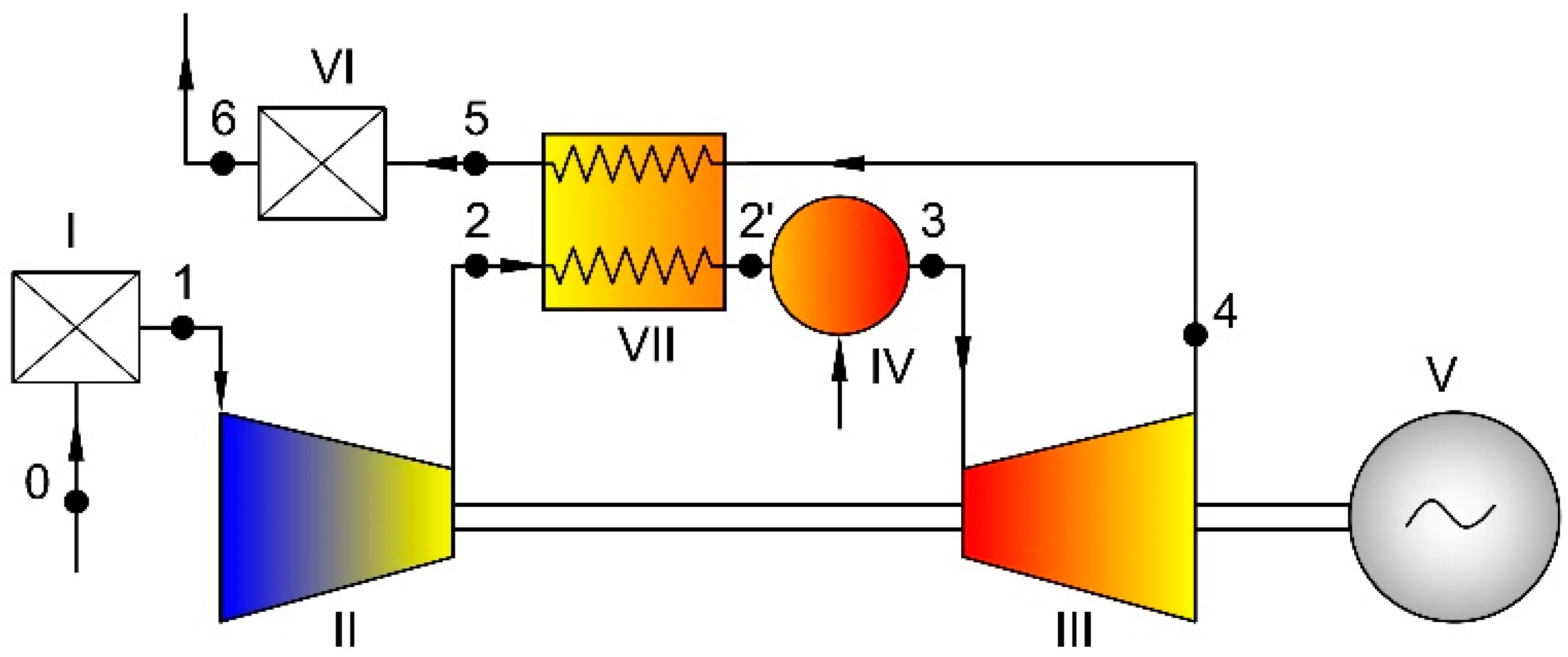
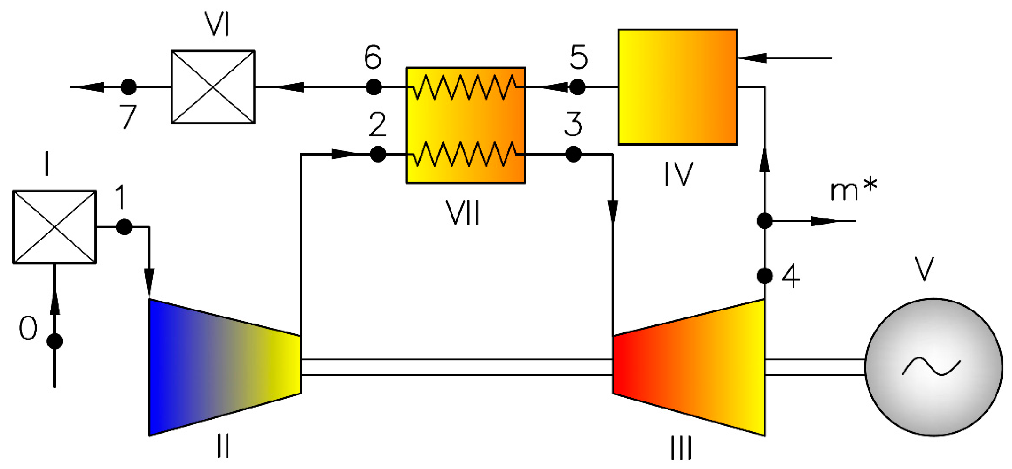
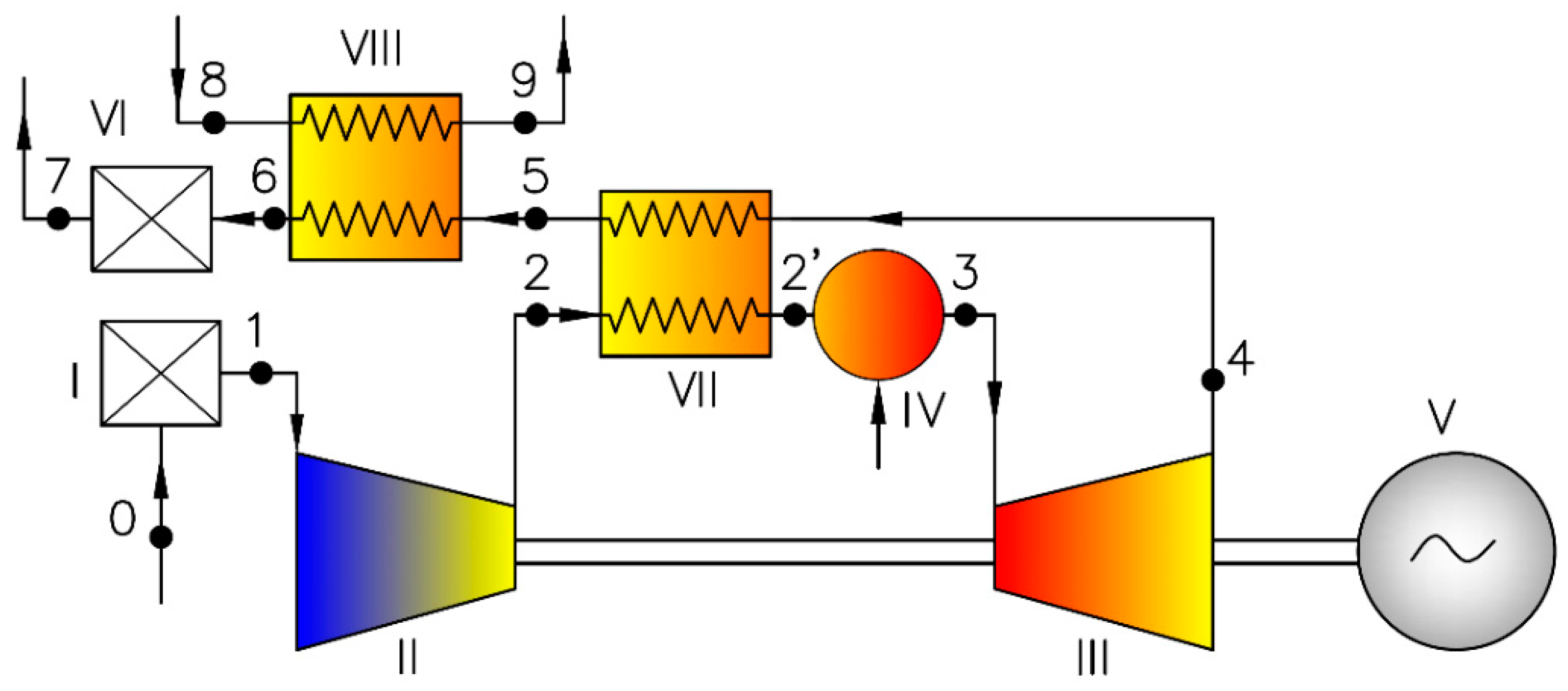
If the fuel of low value of Lower Heating Value (LHV) is used in gas turbine units, the mass flow rate of a turbine exhaust air can be remarkably higher than mass flow rate of compressor air. Thus, in the case of an external combustion chamber, it is possible to bleed some turbine exhaust air and omit a combustion chamber. This original arrangement was compared with the open gas turbine cycle with regenerator. Thus, two variants were considered during the calculations:
  • Variant 1: turbine set operating according to the open cycle with regenerator (Figure 1),
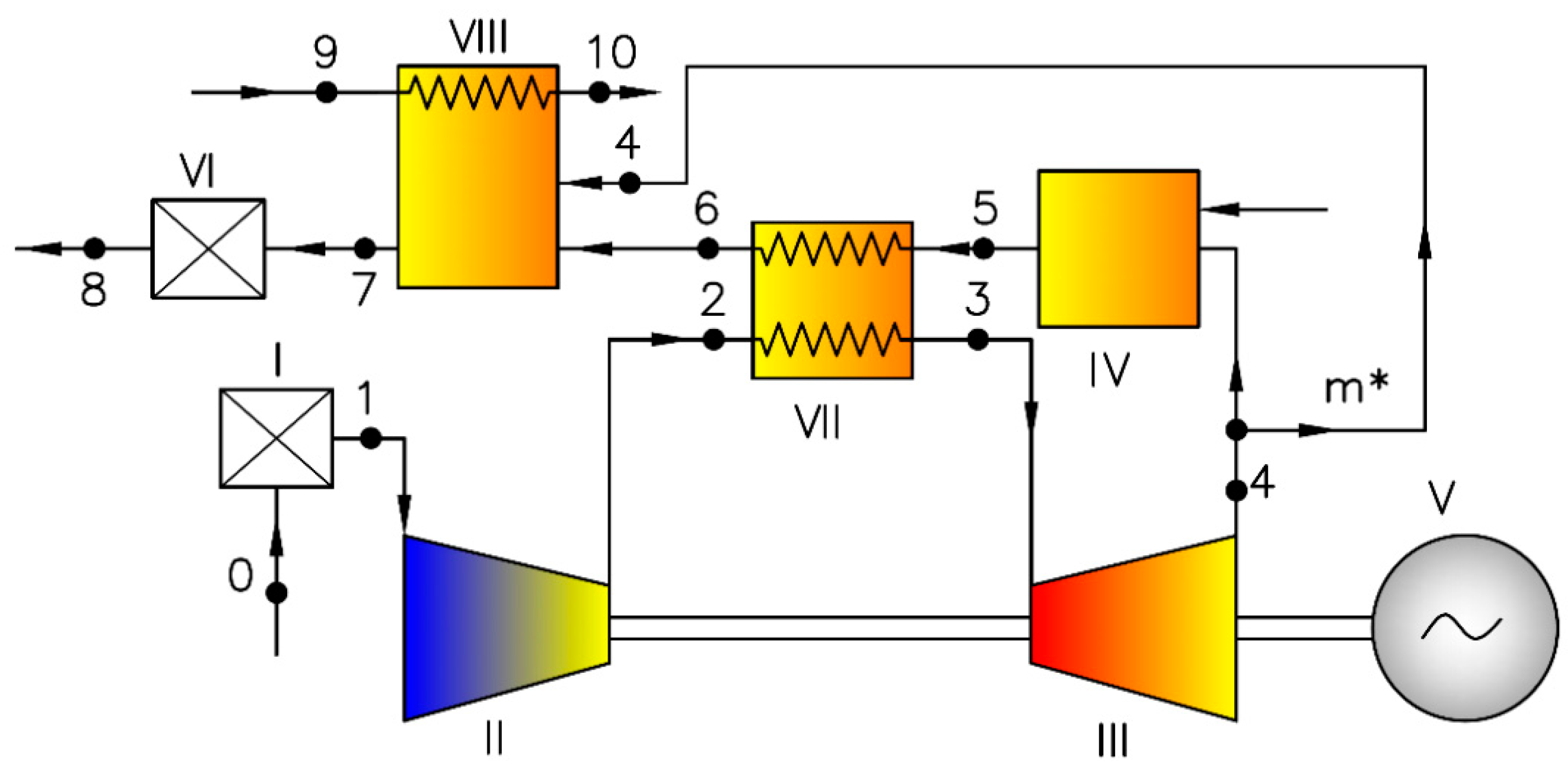
  • Variant 2: turbine set operating according to the open cycle with partial bypassing of external combustion chamber at turbine exit and with high-temperature heat exchanger (Figure 2).

2. Materials and Methods

2.1. Nomentclature and Units

The following list contains the most important symbols and units (Table 1 and Table 2) used in the formulae and in the figures.

2.2. The Computation Algorithm

In the case of small power plants (from several kW to several hundred kW), the maximum temperature 900 °C was assumed before the turbine, and the low efficiency of the components was assumed. Assumptions adopted for the analysis are presented in Table 3.
The results of thermodynamical calculations of the cycles with gas turbines using fuels of different caloric values were presented in the paper. The results are presented for a gas from biomass gasification and for a biogas. For comparison, the analysis was also carried out for methane (the main component of LNG or natural gas). The characteristics of the considered gases are shown in Table 4.
The thermodynamical calculations were performed following classical approach known from the bibliography [27,63,64,65]. The calculations were performed in the following order: the calculations of compression process in the compressor, calculations of expansion line in the turbine, calculations of regenerator and combustion chamber energy balance equations. The following main relationships were used in the analysis, including energy balances and definitions for the efficiencies.
The power and specific work of the gas turbine set are determined accordingly to the dependencies:
W G T = η m · m ˙ T · l T m ˙ C · l C
l G T = W G T m ˙ C = η m · ( m ˙ T m ˙ C ) · l T ( m ˙ C m ˙ C ) · l C = η m · ( m ˙ T m ˙ C ) · l T l C
The specific work of the compressor and turbine are defined by relations:
l C = 1 η C · c p C · T 1 · ( ( p 2 p 1 ) κ C 1 κ C 1 )
l T = η T · c p T · T 3 ( 1 ( p 4 p 3 ) κ T 1 κ T )
The efficiency of the gas turbine cycle is defined as:
η G T = W G T Q ˙ 1
where the heat flux brought to combustion chamber:
Q ˙ 1 = ( m ˙ T · h 3 m ˙ C · h 2 ) 1 η C C = m ˙ f · L H V
After the transformations of the above equations, it was obtained:
η G T = η m · m ˙ T · l T m ˙ C · l C ( m ˙ T · i 3 m ˙ C · i 2 ) · 1 η C C
and:
η T G = η K S · η m · η C · c p T · T 3 T 1 [ 1 ( 1 T ) κ T 1 κ T ] · m ˙ T m ˙ C 1 η C · c p C · [ ( C ) κ C 1 κ C 1 ] m ˙ T m ˙ C · c p C C · T 3 T 1 1 η C · c p C · [ ( C ) κ C 1 κ C 1 ]
The heat flux transferred from the exhaust fumes in the regenerator is that:
Q ˙ V I I ,   T = m ˙ T · ( h 4 h 5 )
The heat flux received by the air in the regenerator is that:
Q ˙ V I I ,   C = m ˙ C · ( h 2 h 2 )
Average values of specific heat for particular states of working media were determined on the basis of their chemical composition and thermodynamical parameters using REFPROP software.

3. Results

Calculations of two variants of cycles were performed (Figure 1 and Figure 2) for three fuels with different lower heating values (
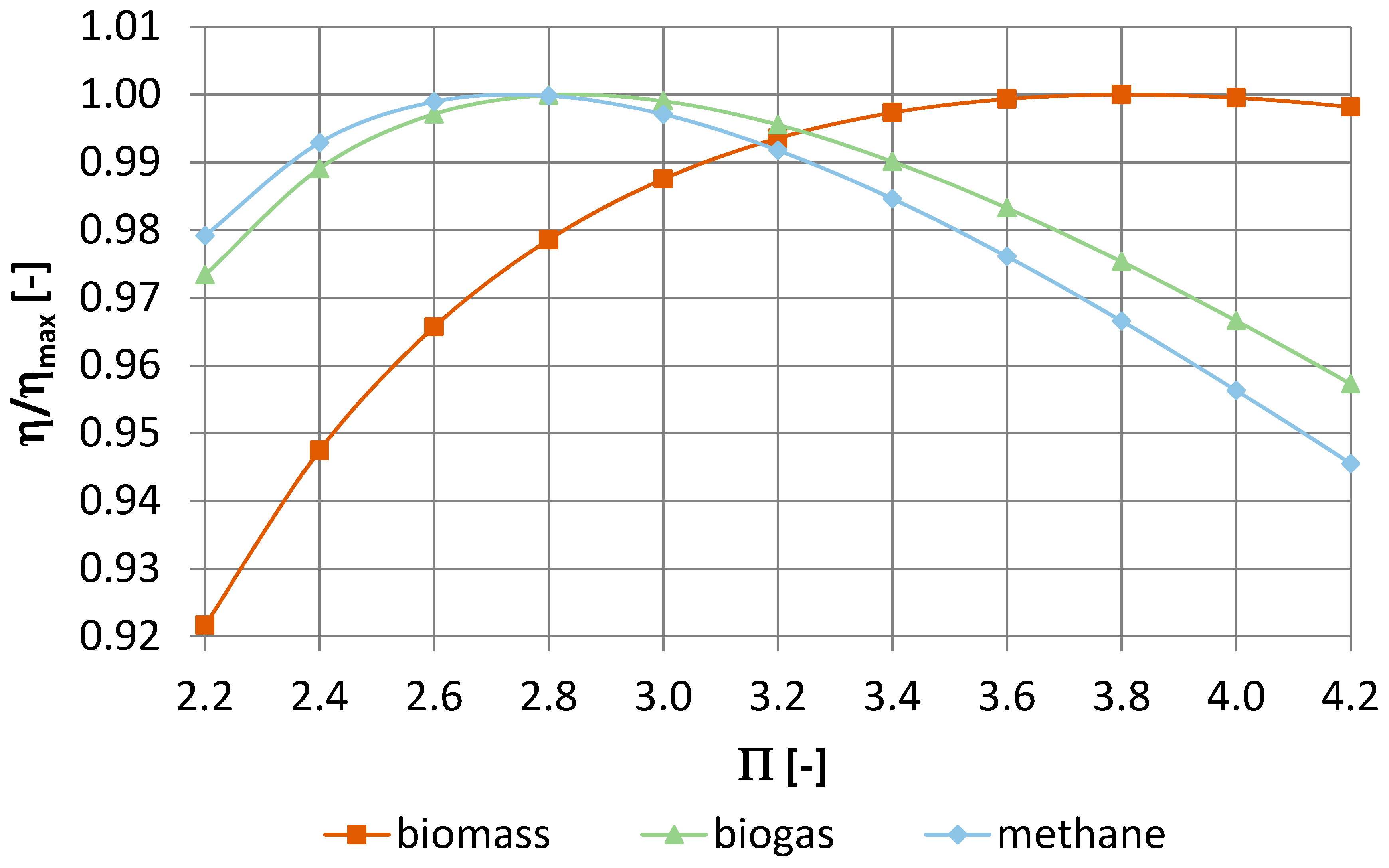
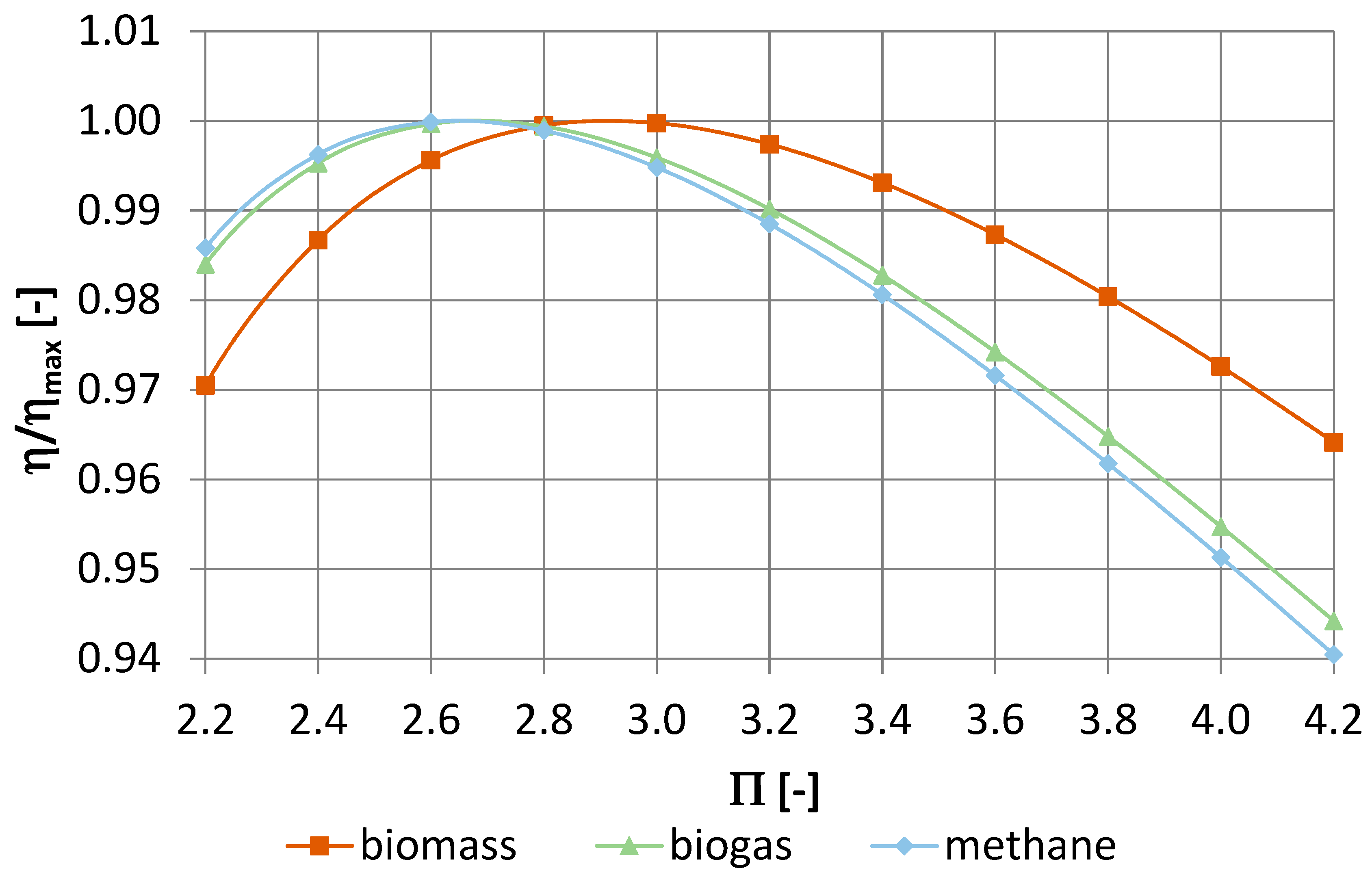
Table 4). The reference was made to the results for methane as a comparative fuel. For each of the analyzed variants, the compression ratio was optimized to obtain maximum efficiency. The effect of the compression on the value of the relative efficiency (referred to the maximum value) for three fuels used in variant 1 is shown in Figure 3, and for variant 2-in 
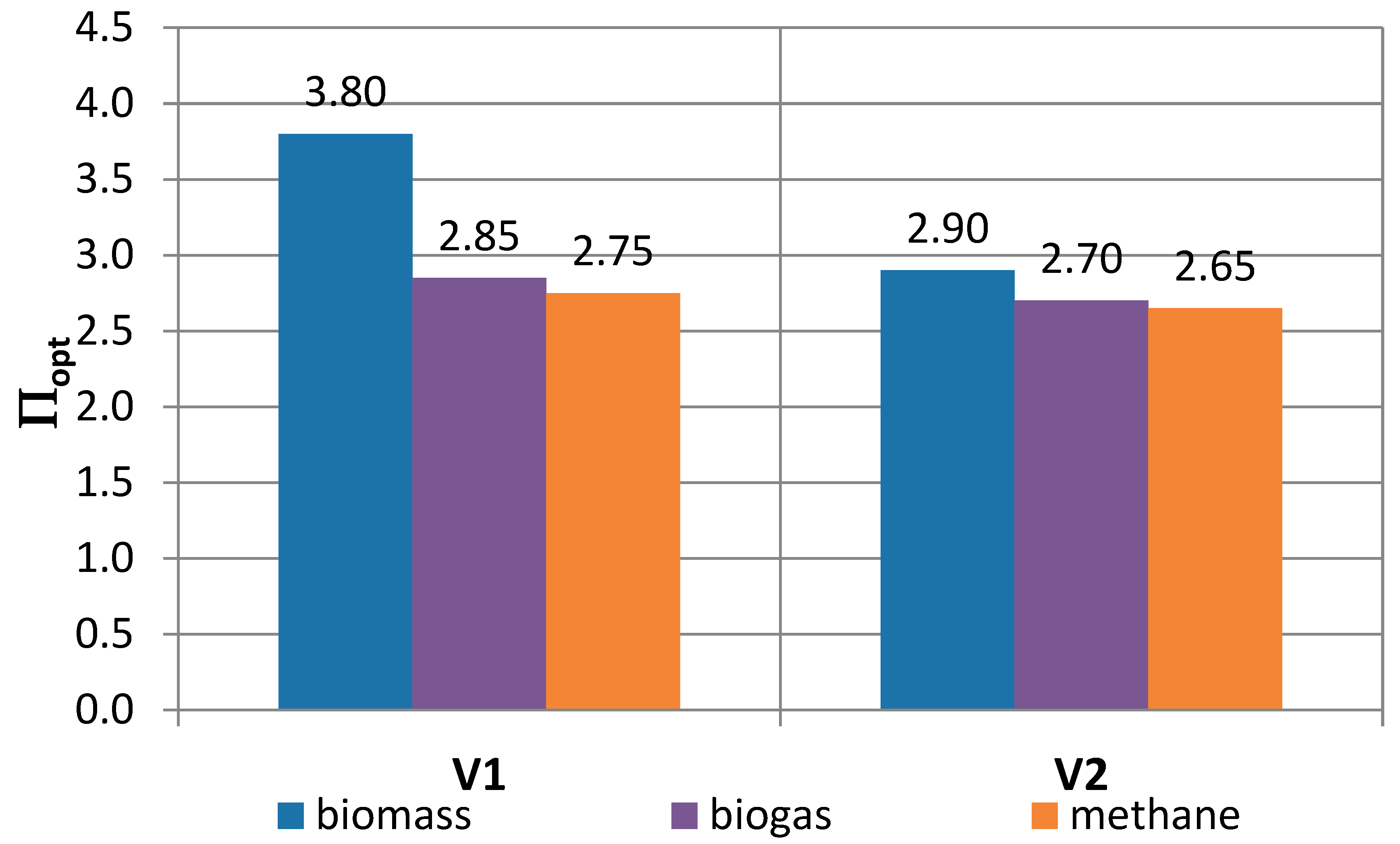
Figure 4. As can be seen, the calorific value shows an effect on the optimal compression (maximum efficiency) only for variant 1, whereas in variant 2 the type of fuel has a little effect on the optimal compression value. This is confirmed by the results shown in Figure 5 (optimal compression values for different types of fuel and both variants).
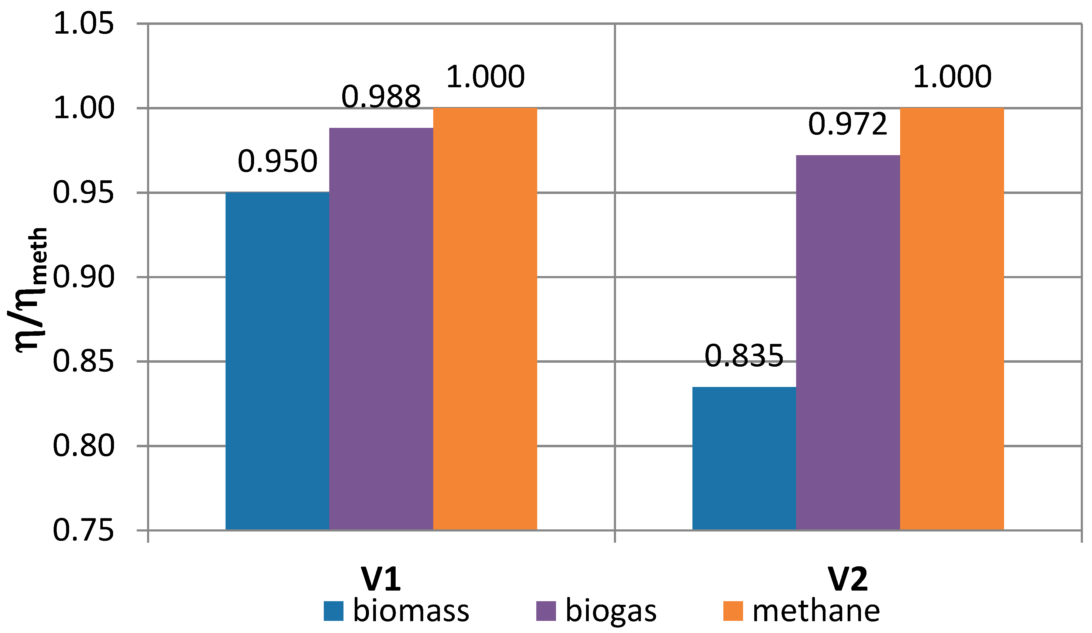
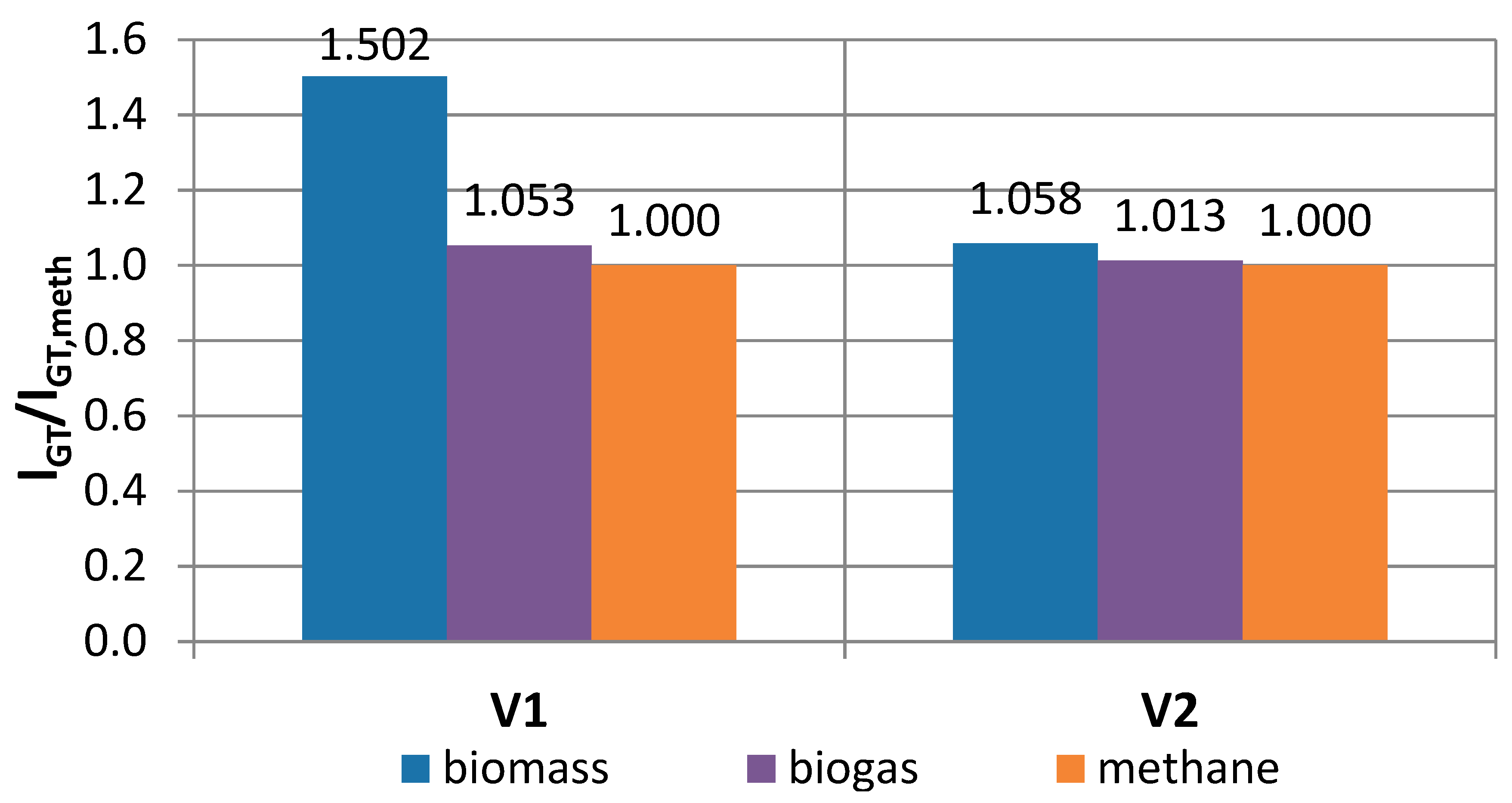
The 
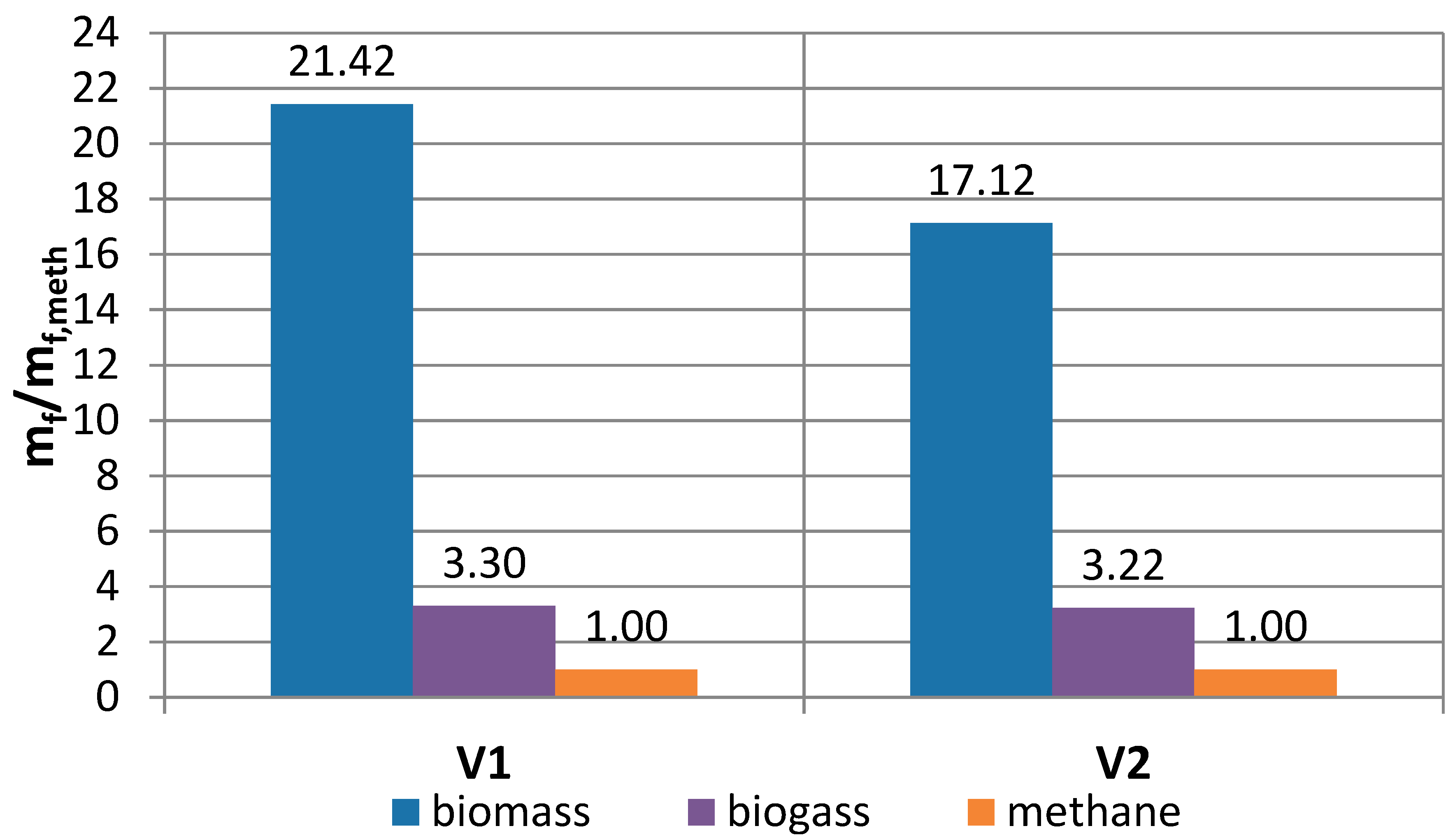
Figure 6, in turn, shows the influence of the structure of the cycle and calorific value of the fuel on the relative efficiency (referred to methane) for both variants of turbine sets. In each case considered, the decrease of calorific value leads to a reduction in the efficiency of the turbine set (from a few to a dozen or so percent). The subsequent figures show the influence of the cycle structure and of calorific value of the fuel on the relative mass flow of fuel combusted in the combustion chamber (
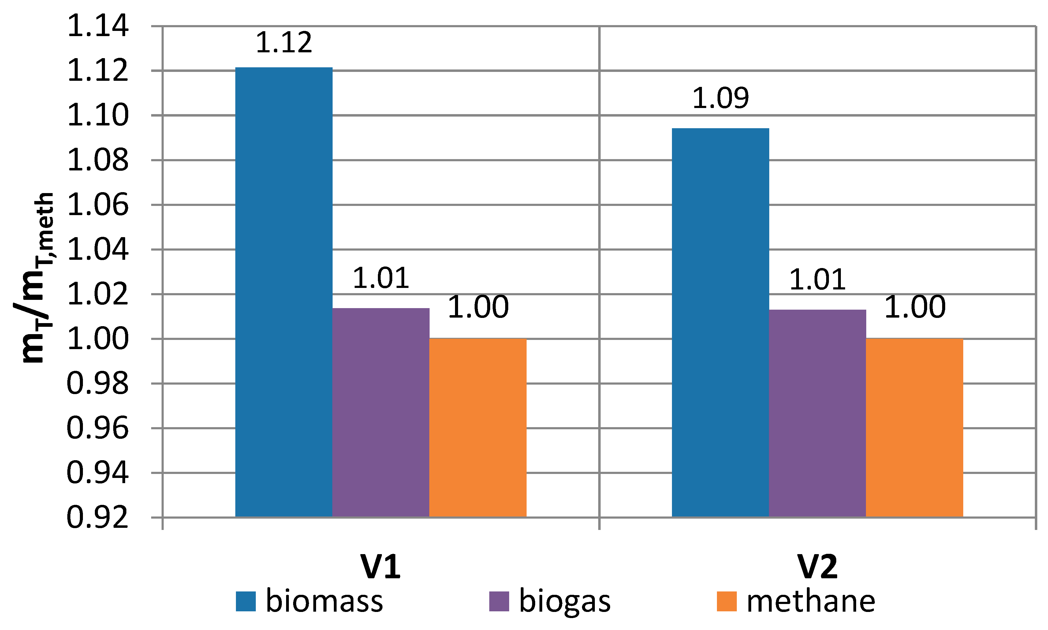
Figure 7), on the relative mass flow of exhaust (Figure 8) and on the relative power of the turbine set all related to the corresponding variants of the cycles with methane used as a fuel (Figure 9).
A decrease of the lower heating value leads to a clear, multiple increase in mass fuel consumption, especially when using low calorific biomass gasification fuel (Figure 7). However, due to the small mass fraction of fuels in relation to air, this does not significantly affect the increase of exhaust gas flow (Figure 8). Only in the case of fuel from biomass, the increase of the flue gas stream may amount to approx. 10% and only in variant 1 this results in a very large increase in the unit power of the turbine set.
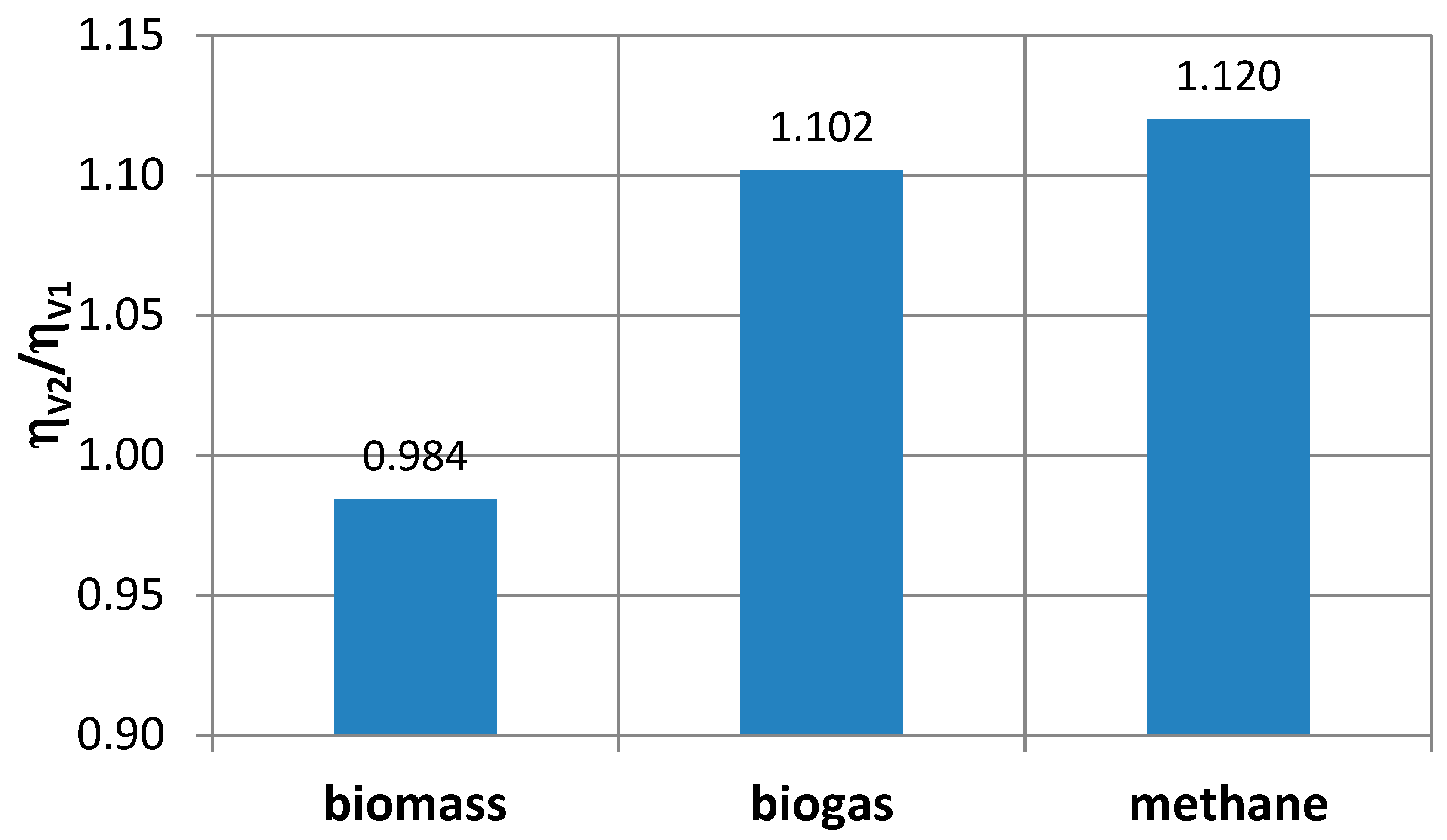
It is interesting to compare directly the efficiency of both variants of the turbine set cycles (V1 and V2). Only for biomass fuel, the variant with the external combustion chamber (V2) appears worse than the classic turbine set with the regenerator (V1). For higher caloricity of the fuel, variant 2 achieves higher efficiency than variant 1, Figure 10.
In the analysis of the work of cycles, one should also consider the possibilities of using energy of exhaust gas in cogeneration systems for generating electricity and heat as well as in combined systems (cooperation with other types of thermal cycles). Therefore, in this analysis the values of the stream intensity and the temperature of the medium leaving the turbine set are important. 
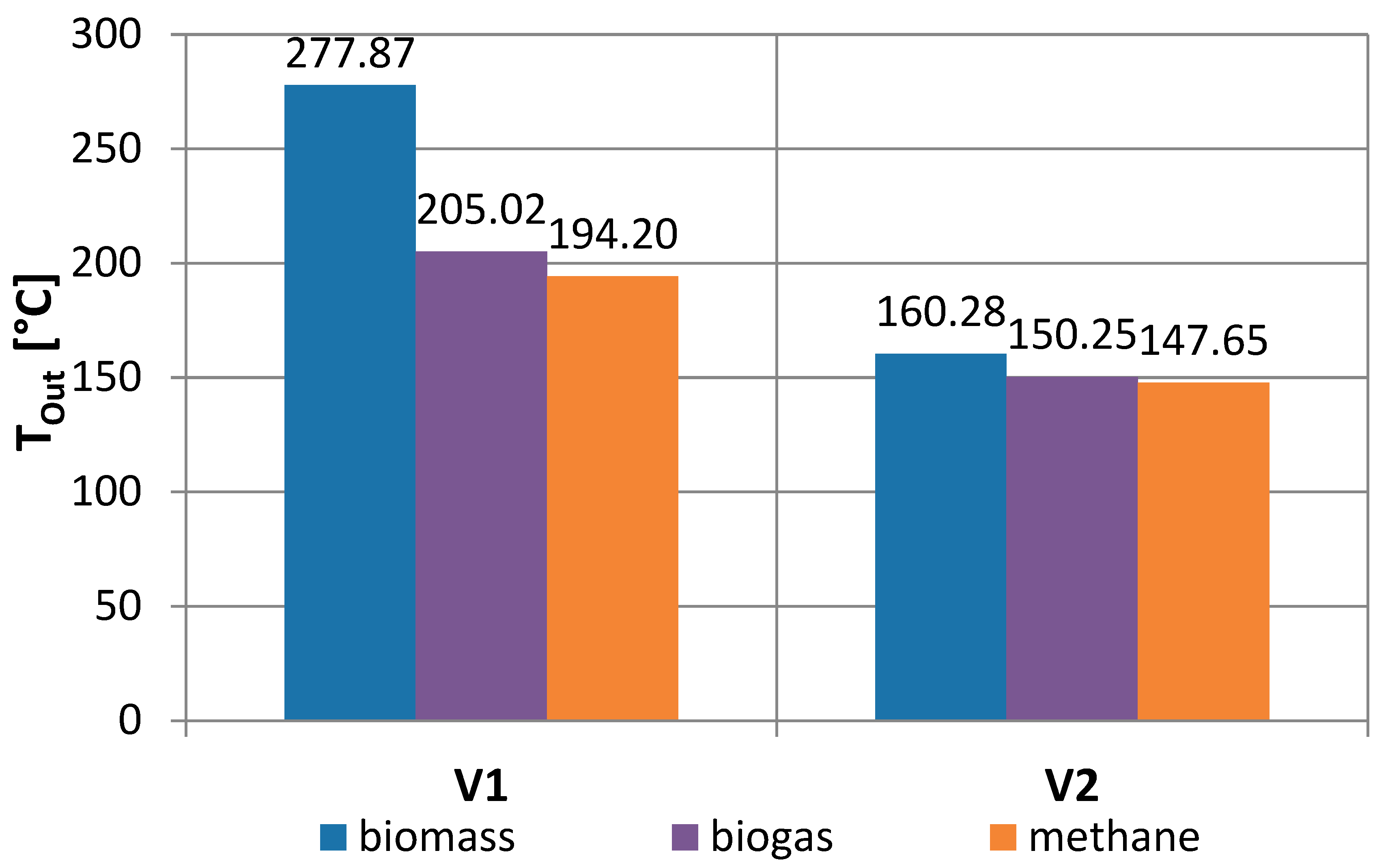
Figure 11 shows the outlet air temperature (after the regenerator) for both variants V1 and V2, and for all the fuels considered. The highest outlet temperatures are for biomass fuel (with the lowest caloricity LHV) for both the regenerator cycle (278 °C) and the cycle with the external combustion chamber (160 °C). Cycles with an external combustion chamber are usually characterized by a lower outlet temperature of the working medium.
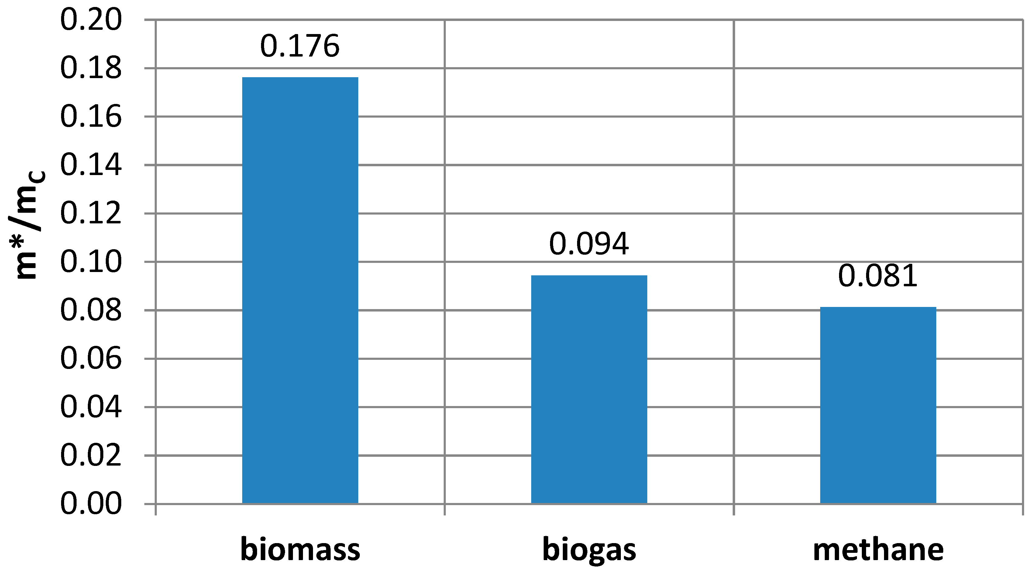
Figure 12 shows the relative air flow drawn from behind the turbine in relation to the air flow through the compressor. It ranges from a few to a dozen or so percent (for the fuel from biomass), but it should be taken into account that it is a high temperature air, which creates greater opportunities for its use, also in combined systems. The possibility of heat production in cogeneration with electricity generation for variants with a regenerator and an external combustion chamber is shown in Figure 13 (variant 3) and Figure 14 (variant 4), respectively.
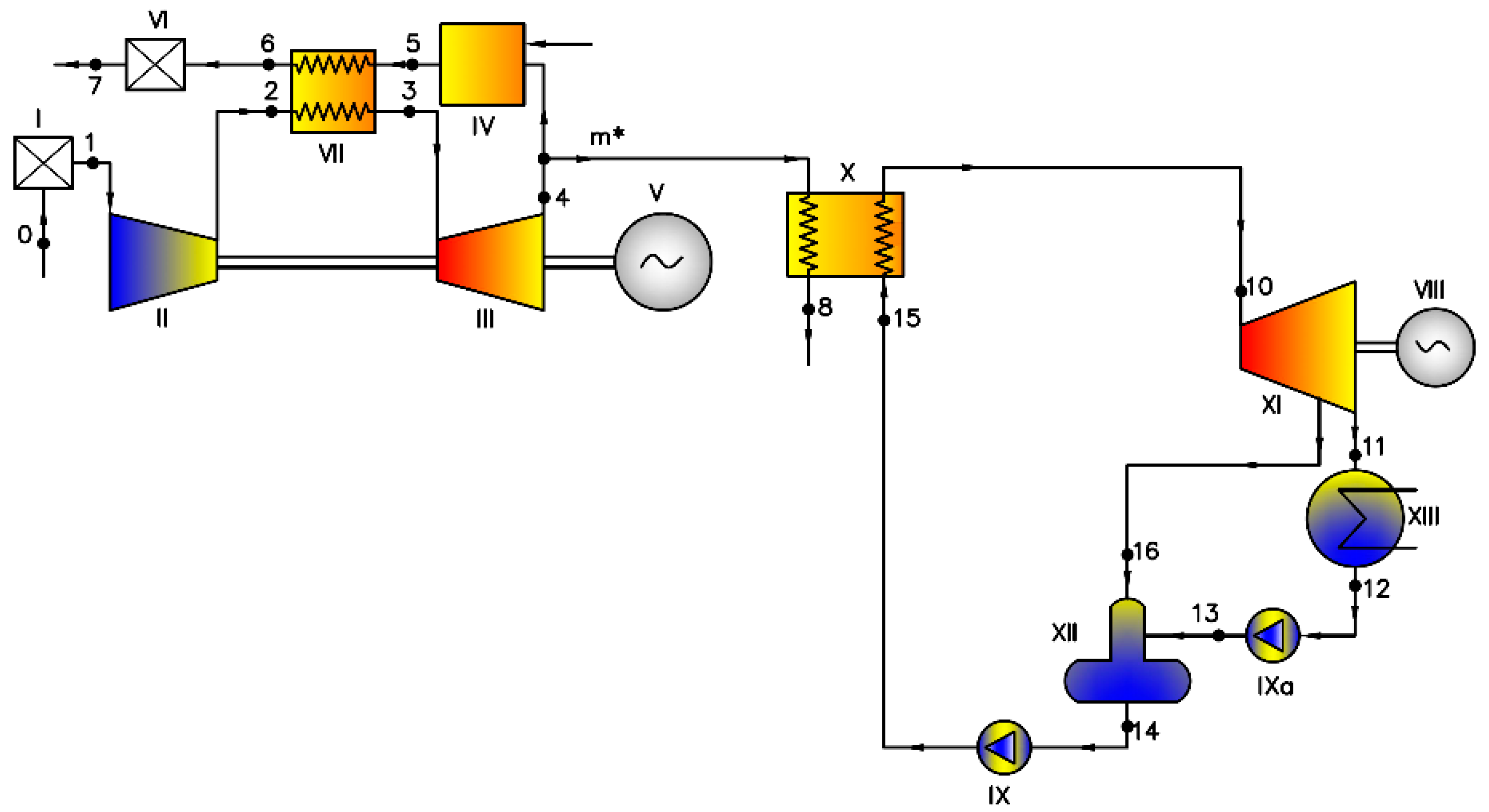
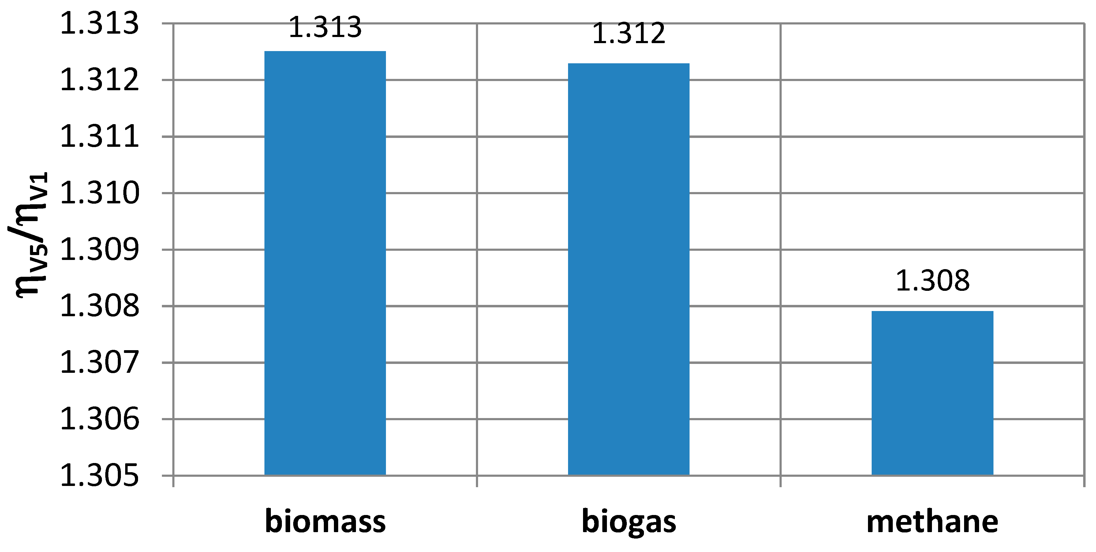
Figure 15 shows a gas turbine with an external combustion chamber and air intake from behind the turbine for combined cycle with a steam turbine (variant 5). This solution increases the electric power generated, and the efficiency of the entire power plant. The comparison of the efficiency of the combined machine (variant 5) with the efficiency of the system with regenerator (variant 1) is shown in Figure 16. Regardless of the fuel used, the efficiency of the combined system (variant 5) exceeded about 30% efficiency of turbine set with regenerator (variant 1).
The results of calculations for the analyzed fuels are presented in Table 5 and Table 6.
All the calculations were performed assuming efficiencies of the main turbine power plants elements. Efficiencies of compressors, turbines, combustion chambers and regenerators (Table 3) can be treated as quite good values for gas turbine sets of small output. If we consider the other values of these parameters, we may expect a change of overall power plant efficiency, for example:
  • applying lower compressor efficiency equal to 0.75 (instead 0.80) we observe the drop of overall efficiency by about 7%–8% for all considered variants while assuming higher compressor efficiency 0.85 the increase in overall efficiency can reach 6.5%–7.5%,
  • decreasing turbine efficiency from 0.82 to 0.77 we lower the overall efficiency by about 9%–10% and increasing it to 0.87 we have the rise in overall efficiency by about 8%–9%,
  • changing the combustion chamber efficiency by 5% the overall efficiency also changes by about 5%,
  • assuming high values of all elements (compressor efficiency −0.85, turbine efficiency −0.87, combustion chamber efficiency −0.985, regenerator efficiency 0.98) we may increase the overall power plant efficiency by 18%–21%,
  • using low values of all elements (compressor efficiency −0.75, turbine efficiency −0.77, combustion chamber efficiency −0.9, regenerator efficiency 0.8) we may reduce the overall power plant efficiency by 28%–32%.
All the considered variants, in spite of the fuel used, are more sensitive to reduction than to growth of the efficiency of particular power plant elements.
For many years, installations with electric power of several hundred kilowatts and more have been used in biomass-burning power plants. Cogeneration systems working with organic media are already available in a wide range of electrical and thermal power, e.g., a power plant with an electrical power of 300–600 kW and a heat power of 1500–2800 kW or a heat and power plant with an electric power of 200–1000 kW and a thermal power of 1000–6000 kW [66]. However, only a few examples of Organic Rankin Cycle (ORC) installations with an output power less than 100 kW [67] or less than 30 kW [68] of electrical power can be found. Only a few examples of ORC cogeneration systems (Organic Rankin Cycle) with an electric power below 5 kW can be found on the market. The published results of experimental studies on the operation of microturbine sets can be found, for example, in [69].
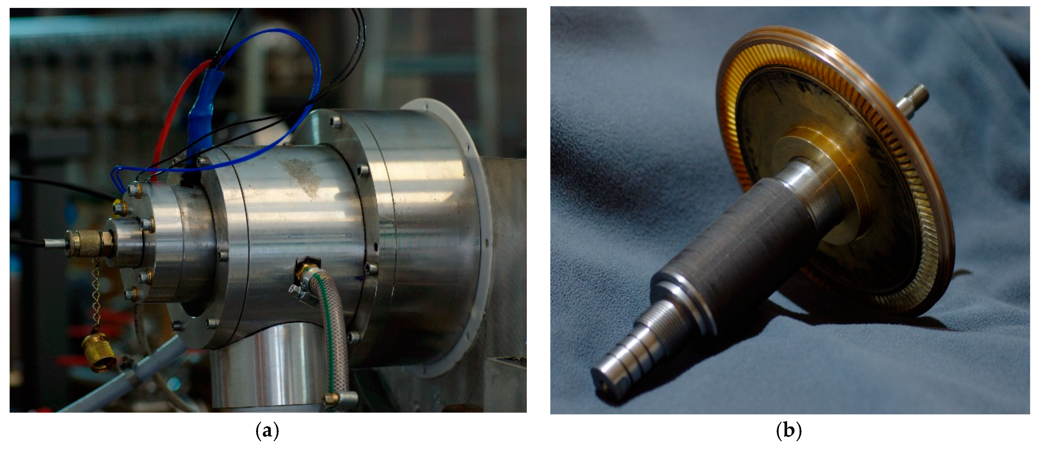
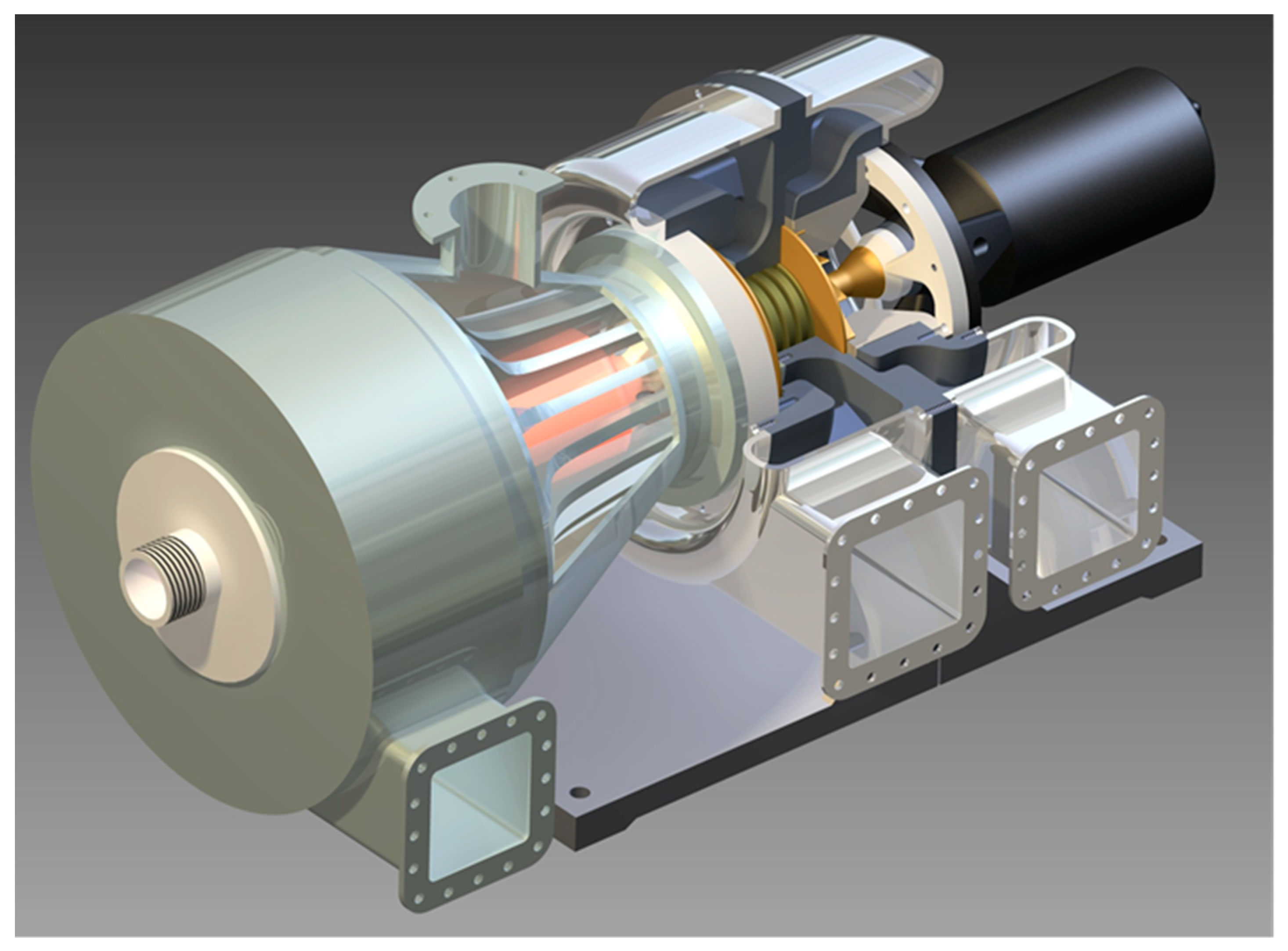
Previous research has shown that it is possible to build a set of microturbines with a capacity of about 2 kW with a higher efficiency than in existing machines [70]. It is worth noting that the relatively high efficiency of microturbines can be achieved thanks to a very careful and advanced design process (Figure 17). The safe and reliable behavior of the microturbine set has been confirmed during operational tests. The results indicate the need to consider the interaction between components of the ORC installation and microturbine.

4. Final Conclusions

The performed analysis have shown that:
  • Systems with an external combustion chamber and air intake from behind the turbine can be competitive in terms of efficiency with classic turbine sets, also those with regeneration.
  • The use of fuels with lower calorific value usually leads to a lower efficiency of the power plant.
  • The structure of the gas turbine power plant and the type of fuel should be taken into account at the stage of determining the main design parameters of the turbine set (e.g., optimal compression ratio, unit power).
  • Turbosets with an external combustion chamber and air intake from behind the turbine are characterized by wide possibilities of applications in cogeneration systems and high efficiency combined systems.
Conducted analyses provide knowledge to help to mitigate potential environmental hazards through introduction of biofuels into distributed energy generation and optimization of turbines to such, locally available fuels.
Energy efficiency solutions provide opportunities for diversification and reduce energy consumption as well as primary consumption. It seems that the efficiency of turbine sets for micro-energetics will clearly increase after the introduction of new high-efficiency thermodynamic cycles. Such effective technological changes and improvements to the system may be one of the stages in the fight against the energy crisis, as well as an element of strategic development in the shaping of the national power generation sector.
The problem still requires further research, but implementation of the final might contribute to the reduction of environmental burdens.
At present two experimental micro power plants with external combustion chambers are being built: a domestic cogeneration power plant of 20 kW heat power and 2 kW electric power as well as a high efficiency turbine power plant with an innovative isothermal turbine of 5 kW (Figure 18).

Author Contributions

Conceptualization, K.K. and M.P.; R.S.; W.W.; Methodology, K.T. and O.O.; D.M.; Investigation, R.S. and W.W.; Writing—Original Draft Preparation, K.T.; M.P. and O.O.; Funding Acquisition, K.K. and D.M.

Funding

The Authors wish to express their deep gratitude to Gdansk University of Technology for financial support given to the present publication (Krzysztof Kosowski). The research was carried out under financial support obtained from the research subsidy of the Faculty of Engineering Management (WIZ) of Bialystok University of Technology (Olga Orynycz).

Conflicts of Interest

The authors declare no conflict of interest. The funders had no role in the design of the study; in the collection, analyses, or interpretation of data; in the writing of the manuscript, and in the decision to publish the results.

References

  1. Maczynska, J.; Krzywonos, M.; Kupczyk, A.; Tucki, K.; Sikora, M.; Pinkowska, H.; Baczyk, A.; Wielewska, I. Production and use of biofuels for transport in Poland and Brazil. The case of bioethanol. Fuel 2019, 241, 989–996. [Google Scholar] [CrossRef]
  2. Tucki, K.; Mruk, M.; Orynycz, O.; Botwinska, K.; Gola, A. Toxicity of Exhaust Fumes (CO, NOx) of the Compression-Ignition (Diesel) Engine with the Use of Simulation. Sustainability 2019, 11, 2188. [Google Scholar] [CrossRef]
  3. Tucki, K.; Mruk, R.; Orynycz, O.; Wasiak, A.; Botwinska, K.; Gola, A. Simulation of the Operation of a Spark Ignition Engine Fueled with Various Biofuels and Its Contribution to Technology Management. Sustainability 2019, 11, 2799. [Google Scholar] [CrossRef]
  4. Braungardt, S.; Bürger, V.; Zieger, J.; Bosselaar, L. How to include cooling in the EU Renewable Energy Directive? Strategies and policy implications. Energy Policy 2019, 129, 260–267. [Google Scholar] [CrossRef]
  5. Veum, K.; Bauknecht, D. How to reach the EU renewables target by 2030? An analysis of the governance framework. Energy Policy 2019, 127, 299–307. [Google Scholar] [CrossRef]
  6. Gökgöz, F.; Güvercin, M.T. Energy security and renewable energy efficiency in EU. Renew. Sustain. Energy Rev. 2018, 96, 226–239. [Google Scholar] [CrossRef]
  7. Xu, G.; Li, M.; Lu, P. Experimental investigation on flow properties of different biomass and torrefied biomass powders. Biomass Bioenergy 2019, 122, 63–75. [Google Scholar] [CrossRef]
  8. Goffé, J.; Ferrasse, J.H. Stoichiometry impact on the optimum efficiency of biomass conversion to biofuels. Energy 2019, 170, 438–458. [Google Scholar]
  9. Tucki, K.; Orynycz, O.; Wasiak, A.; Swic, A.; Wichlacz, J. The Impact of Fuel Type on the Output Parameters of a New Biofuel Burner. Energies 2019, 12, 1383. [Google Scholar] [CrossRef]
  10. Bunn, D.W.; Redondo-Martin, J.; Munoz-Hernandez, J.I.; Diaz-Cachinero, P. Analysis of coal conversion to biomass as a transitional technology. Renew. Energy 2019, 132, 752–760. [Google Scholar] [CrossRef]
  11. Hamelin, L.; Borzęcka, M.; Kozak, M.; Pudełko, R. A spatial approach to bioeconomy: Quantifying the residual biomass potential in the EU-27. Renew. Sustain. Energy Rev. 2019, 100, 127–142. [Google Scholar] [CrossRef]
  12. Holland, R.A.; Beaumont, N.; Hooper, T.; Austen, M.; Gross, R.J.K.; Heptonstall, P.J.; Ketsopoulou, I.; Winskel, M.; Watson, J.; Taylor, G. Incorporating ecosystem services into the design of future energy systems. Appl. Energy 2018, 222, 812–822. [Google Scholar] [CrossRef]
  13. Picchi, P.; Van Lierop, M.; Geneletti, D.; Stremke, S. Advancing the relationship between renewable energy and ecosystem services for landscape planning and design: A literature review. Ecosyst. Serv. 2019, 35, 241–259. [Google Scholar] [CrossRef]
  14. Tucki, K.; Mruk, R.; Orynycz, O.; Gola, A. The Effects of Pressure and Temperature on the Process of Auto-Ignition and Combustion of Rape Oil and Its Mixtures. Sustainability 2019, 11, 3451. [Google Scholar] [CrossRef]
  15. Wasiak, A.; Orynycz, O. The effects of energy contributions into subsidiary processes on energetic efficiency of biomass plantation supplying biofuel production system. Agric. Agric. Sci. Procedia 2015, 7, 292–300. [Google Scholar] [CrossRef]
  16. Moslehi, S.; Reddy, T.A. An LCA methodology to assess location-specific environmental externalities of integrated energy systems. Sustain. Cities Soc. 2019, 46, 1–14. [Google Scholar] [CrossRef]
  17. Kupczyk, A.; Maczynska, J.; Redlarski, G.; Tucki, K.; Baczyk, A.; Rutkowski, D. Selected Aspects of Biofuels Market and the Electromobility Development in Poland: Current Trends and Forecasting Changes. Appl. Sci. 2019, 9, 254. [Google Scholar] [CrossRef]
  18. Kosowski, K.; Tucki, K.; Kosowski, A. Application of Artificial Neural Networks in Investigations of Steam Turbine Cascades. J. Turbomach. Trans. ASME 2010, 132, 014501–014505. [Google Scholar] [CrossRef]
  19. Kosowski, K.; Tucki, K.; Kosowski, A. Turbine stage design aided by artificial intelligence methods. Expert Syst. Appl. 2009, 36, 11536–11542. [Google Scholar] [CrossRef]
  20. IEO Report PV Market in Poland 2019. Available online: www.ieo.en/ (accessed on 17 July 2019).
  21. Tucki, K.; Orynycz, O.; Wasiak, A.; Świć, A.; Dybaś, W. Capacity market implementation in Poland: Analysis of a survey on consequences for the electricity market and for energy management. Energies 2019, 12, 839. [Google Scholar] [CrossRef]
  22. Baatz, B.; Relf, G.; Nowak, S. The role of energy efficiency in a distributed energy future. Electr. J. 2018, 31, 13–16. [Google Scholar] [CrossRef]
  23. Puri, S.; Perera, A.T.D.; Mauree, D.; Coccolo, S.; Delannoy, L.; Scartezzini, J.L. The role of distributed energy systems in European energy transition. Energy Procedia 2019, 159, 286–291. [Google Scholar] [CrossRef]
  24. Calise, F.; De Notaristefani di Vastogirardi, G.; D’Accadia, M.D.; Vicidomini, M. Simulation of polygeneration systems. Energy 2018, 163, 290–337. [Google Scholar] [CrossRef]
  25. Jarnut, M.; Wermiński, S.; Waśkowicz, B. Comparative analysis of selected energy storage technologies for prosumer-owned microgrids. Renew. Sustain. Energy Rev. 2017, 74, 925–937. [Google Scholar] [CrossRef]
  26. Aiying, R.; Risto, L. Role of polygeneration in sustainable energy system development: Challenges and opportunities from optimization viewpoints. Renew. Sustain. Energy Rev. 2016, 53, 363–372. [Google Scholar]
  27. Kosowski, K.; Domachowski, Z.; Próchnicki, W.; Kosowski, A.; Stępień, R.; Piwowarski, M.; Włodarski, W.; Ghaemi, M.; Tucki, K.; Gardzilewicz, A.; et al. Steam and Gas Turbines with the Examples of Alstom Technology, 1st ed.; Alstom: Saint-Quen, France, 2007; ISBN 978-83-925959-3-9. [Google Scholar]
  28. Krzywonos, M.; Tucki, K.; Wojdalski, J.; Kupczyk, A.; Sikora, M. Analysis of Properties of Synthetic Hydrocarbons Produced Using the ETG Method and Selected Conventional Biofuels Made in Poland in the Context of Environmental Effects Achieved. Rocz. Ochr. Śr. 2017, 19, 394–410. [Google Scholar]
  29. Tonini, D.; Hamelin, L.; Alvarado-Morales, M.; Astrup, T.F. GHG emission factors for bioelectricity, biomethane, and bioethanol quantified for 24 biomass substrates with consequential life-cycle assessment. Bioresour. Technol. 2016, 208, 123–133. [Google Scholar] [CrossRef] [Green Version]
  30. Shen, X.; Kommalapati, R.R.; Huque, Z. The Comparative Life Cycle Assessment of Power Generation from Lignocellulosic Biomass. Sustainability 2015, 7, 12974. [Google Scholar] [CrossRef]
  31. Carneiro, M.L.N.M.; Pradelle, F.; Braga, S.L.; Gomes, M.S.P.; Martins, M.R.F.A.; Turkovics, F.; Pradelle, R.N.C. Potential of biofuels from algae: Comparison with fossil fuels, ethanol and biodiesel in Europe and Brazil through life cycle assessment (LCA). Renew. Sustain. Energy Rev. 2017, 73, 632–653. [Google Scholar] [CrossRef]
  32. Adelt, M.; Wolf, D.; Vogel, A. LCA of biomethane. J. Nat. Gas Sci. Eng. 2011, 3, 646–650. [Google Scholar] [CrossRef]
  33. Ardolino, F.; Arena, U. Biowaste-to-Biomethane: An LCA study on biogas and syngas roads. Waste Manag. 2019, 87, 441–453. [Google Scholar] [CrossRef] [PubMed]
  34. Rocha, M.H.; Capaz, R.S.; Lora, E.E.S.; Nogueira, L.A.H.; Leme, M.M.V.; Renó, M.L.G.; Del Olmo, O.A. Life cycle assessment (LCA) for biofuels in Brazilian conditions: A meta-analysis. Renew. Sustain. Energy Rev. 2014, 37, 435–459. [Google Scholar] [CrossRef]
  35. Collotta, M.; Champagne, P.; Mabee, W.; Tomasoni, G.; Leite, G.B.; Busi, L.; Alberti, M. Comparative LCA of Flocculation for the Harvesting of Microalgae for Biofuels Production. Procedia CIRP 2017, 61, 756–760. [Google Scholar] [CrossRef]
  36. Milledge, J.J.; Heaven, S. Energy Balance of Biogas Production from Microalgae: Effect of Harvesting Method, Multiple Raceways, Scale of Plant and Combined Heat and Power Generation. J. Mar. Sci. Eng. 2017, 5, 9. [Google Scholar] [CrossRef]
  37. Gonzalez-Fernandez, C.; Sialve, B.; Bernet, N.; Steyer, J.P. Impact of microalgae characteristics on their conversion to biofuel. Part ii: Focus on biomethane production. Biofuels Bioprod. Biorefining 2012, 6, 205–218. [Google Scholar] [CrossRef]
  38. Igliński, B.; Iglińska, A.; Kujawski, W.; Buczkowski, R.; Cichosz, M. Bioenergy in Poland. Renew. Sustain. Energy Rev. 2011, 15, 2999–3007. [Google Scholar] [CrossRef]
  39. Experimental Algae to Grow at the Refinery. Available online: https://www.orlen.pl/ (accessed on 17 July 2019).
  40. PKN ORLEN Invests in Biofuels of the Future. Available online: https://www.orlen.pl/ (accessed on 17 July 2019).
  41. ORLEN Group 2017. Integrated Report. Available online: https://raportzintegrowany2017.orlen.pl/ (accessed on 17 July 2019).
  42. Unipetrol Enters the BIOENERGY 2020+ project. Available online: http://www.unipetrol.cz (accessed on 17 July 2019).
  43. Lisowski, A. Technologie Zbioru Roślin Energetycznych (Energy Plants Harvesting Technologies), 1st ed.; Wydawnictwo SGGW: Warszawa, Polska, 2010; pp. 77–119. [Google Scholar]
  44. Stolarski, M.J.; Niksa, D.; Krzyżaniak, M.; Tworkowski, J.; Szczukowski, S. Willow productivity from small- and large-scale experimental plantations in Poland from 2000 to 2017. Renew. Sustain. Energy Rev. 2019, 101, 461–475. [Google Scholar] [CrossRef]
  45. Cozzolino, R.; Lombardi, L.; Tribioli, L. Use of biogas from biowaste in a solid oxide fuel cell stack: Application to an off-grid power plant. Renew. Energy 2017, 111, 781–791. [Google Scholar] [CrossRef]
  46. Saadabadi, S.A.; Thattai, A.T.; Fan, L.; Lindeboom, R.E.F.; Spanjers, H.; Aravind, P.V. Solid Oxide Fuel Cells fuelled with biogas: Potential and constraints. Renew. Energy 2019, 134, 194–214. [Google Scholar] [CrossRef]
  47. Mikielewicz, J.; Piwowarski, M.; Kosowski, K. Design analysis of turbines for co-generating micro-power plant working in accordance with organic rankine’s cycle. Pol. Marit. Res. 2009, 1, 34–38. [Google Scholar] [CrossRef]
  48. Stępniak, D.; Piwowarski, M. Analyzing selection of low-temperature medium for cogeneration micro power plant. Pol. J. Environ. Stud. 2014, 23, 1417–1421. [Google Scholar]
  49. Tucki, K.; Sikora, M. Technical and logistics analysis of the extension of the energy supply system with the cogeneration unit supplied with biogas from the water treatment plant. TEKA of the Commission of Motorization and Power Industry in Agriculture 2016, 16, 71–75. [Google Scholar]
  50. Piwowarski, M.; Kosowski, K. Design analysis of combined gas-vapour micro power plant with 30 kw air turbine. Pol. J. Environ. Stud. 2014, 23, 1397–1401. [Google Scholar]
  51. Kosowski, K.; Tucki, K.; Piwowarski, M.; Stępień, R.; Orynycz, O.; Włodarski, W.; Bączyk, A. Thermodynamic Cycle Concepts for High-Efficiency Power Plans. Part A: Public Power Plants 60+. Sustainability 2019, 11, 554. [Google Scholar] [CrossRef]
  52. Giorgetti, S.; Parente, A.; Bricteux, L.; Contino, F.; De Paepe, W. Optimal design and operating strategy of a carbon-clean micro gas turbine for combined heat and power applications. International Journal of Greenhouse Gas Control 2019, 88, 469–481. [Google Scholar] [CrossRef]
  53. De Paepe, W.; Coppitters, D.; Abraham, S.; Tsirikoglou, P.; Ghorbaniasl, G.; Contino, F. Robust Operational Optimization of a Typical micro Gas Turbine. Energy Procedia 2019, 158, 5795–5803. [Google Scholar] [CrossRef]
  54. Lampart, P.; Kosowski, K.; Piwowarski, M.; Jędrzejewski, L. Design analysis of tesla micro-turbine operating on a low-boiling medium. Pol. Marit. Res. 2009, 1, 28–33. [Google Scholar] [CrossRef]
  55. Kabir, E.; Kumar, P.; Kumar, S.; Adelodun, A.A.; Kim, K.H. Solar energy: Potential and future prospects. Renew. Sustain. Energy Rev. 2018, 82, 894–900. [Google Scholar] [CrossRef]
  56. Palm, J.; Eidenskog, M.; Luthander, R. Sufficiency, change, and flexibility: Critically examining the energy consumption profiles of solar PV prosumers in Sweden. Energy Res. Soc. Sci. 2018, 39, 12–18. [Google Scholar] [CrossRef]
  57. Chordia, L. High temperature heat exchanger design and fabrication for systems with large pressure differentials. In Final Scientific/Technical Report 2017. Available online: www.osti.gov/servlets/purl/1349235 (accessed on 17 July 2019).
  58. The exceptional performance of Heatric PCHE heat exchangers. Available online: www.heatric.com/heat_exchanger_performance.html (accessed on 17 July 2019).
  59. Ślefarski, R.; Jójka, J.; Czyżewski, P.; Grzymisławski, P. Experimental investigation on syngas reburning process in a gaseous fuel firing semi-industrial combustion chamber. Fuel 2018, 217, 490–498. [Google Scholar] [CrossRef]
  60. Włodarski, W. Control of a vapour microturbine set in cogeneration applications. ISA Transa. 2019, in press. [Google Scholar] [CrossRef]
  61. Taler, J.; Mruk, A.; Cisek, J.; Majewski, K. Combined heat and power plant with internal combustion engine fuelled by wood gas. Rynek Energii 2013, 4, 62–67. [Google Scholar]
  62. Kordylewski, W. Spalanie i Paliwa, 5th ed.; Oficyna Wydawnicza Politechniki Wrocławskiej: Wrocław, Polska, 2008; pp. 10–470. ISBN 978-83-7493-378-0. [Google Scholar]
  63. Traupel, W. Thermische Turbomachinen, 2nd ed.; Springer: Berlin, Heidelberg; New York, NY, USA, 1982; pp. 122–525. Available online: https://link.springer.com/book/10.1007%2F978-3-642-96632-3 (accessed on 12 August 2019).
  64. Sawyer, J.W. Gas Turbine Engineering Handbook, 3rd ed.; Turbomachinery International Publications: Norwalk, CT, USA, 1985; pp. 98–245. ISBN 0-937506-14-1. [Google Scholar]
  65. Sorensen, H.A. Gas Turbines (Series in Mechanical Engineering), 1st ed.; Ronald Press Company: New York, NY, USA, 1951; pp. 48–440. [Google Scholar]
  66. Gailfuß, M. Private meets Public—Small Scale CHP; Technological Developments, Workshop BHKW-Infozentrum Rastatt 09.09.2003: Berlin, Germany, 2003. [Google Scholar]
  67. Kosowski, K.; Piwowarski, M.; Stępień, R.; Włodarski, W. Design and Investigations of a Micro-Turbine Flow Part. In Proceedings of the ASME Turbo Expo 2012: Turbine Technical Conference and Exposition; Volume 5: Manufacturing Materials and Metallurgy; Marine; Microturbines and Small Turbomachinery; Supercritical CO2 Power Cycles, Copenhagen, Denmark, 11–15 June 2012; Paper No. GT2012-69222. pp. 807–814. [Google Scholar] [CrossRef]
  68. Mills, D. Advances in solar thermal electricity technology. Solar Energy 2004, 76, 19–31. [Google Scholar] [CrossRef]
  69. Kosowski, K.; Włodarski, W.; Piwowarski, M.; Stepień, R. Performance characteristics of a micro-turbine. Adv. Vib. Eng. 2014, 2, 341–350. [Google Scholar]
  70. Kosowski, K.; Piwowarski, M.; Stępień, R.; Włodarski, W. Design and investigations of the ethanol microturbine. Arch. Thermodyn. 2018, 39, 41–54. [Google Scholar]
Figure 1. Turbine set operating according to the open cycle with regenerator (Variant 1-V1). I–filter; II–compressor; III–turbine; IV–combustion chamber; V–electric generator; VI–silencer; VII–regenerator.
Energies 12 03501 g001
Figure 2. Turbine set operating according to the open cycle with partial bypassing of the external combustion chamber at the turbine exit and with a high-temperature heat exchanger (Variant 2 -V2). I–filter; II–compressor; III–turbine; IV–external combustion chamber; V–electric generator; VI–silencer; VII–regenerator.
Energies 12 03501 g002
Figure 3. Effect of compression ratio ∏ on the value of relative efficiency (referred to the maximum value) for three example fuels in variant 1.
Energies 12 03501 g003
Figure 4. Effect of compression ratio ∏ on the value of relative efficiency (referred to the maximum value) for three exemplary fuels in variant 2.
Energies 12 03501 g004
Figure 5. Influence of the structure of the cycle and calorific value of fuel on the optimal compression.
Energies 12 03501 g005
Figure 6. The influence of the structure of the cycle and calorific value of the fuel on the relative efficiency (referred to methane) for both variants of turbine sets.
Energies 12 03501 g006
Figure 7. The influence of the structure of the cycle and calorific value of fuel on the relative mass stream of the fuel in the combustion chamber for both variants (referred to methane as a fuel).
Energies 12 03501 g007
Figure 8. Effect of the structure of the cycle and calorific value of fuel on the exhaust gas mass flow for both variants (related to methane used as a fuel).
Energies 12 03501 g008
Figure 9. The influence of the structure of the cycle and calorific value of fuel for both variants on the effective power related to that with methane as a fuel.
Energies 12 03501 g009
Figure 10. The influence of calorific value of the fuel on the efficiency ratio of the cycles with the external combustion chamber and bypass (V2), and for with the regenerator (V1).
Energies 12 03501 g010
Figure 11. The influence of the calorific value of the fuel and the structure of the cycle on temperature of exhaust gas leaving the turbine set.
Energies 12 03501 g011
Figure 12. The influence of the calorific value of the fuel on the relative mass stream of the bypass to the mass flow of air flowing through the compressor for the optimal compression ratio.
Energies 12 03501 g012
Figure 13. Circulation diagram with a gas turbine with a regenerator and cogeneration (Variant 3-V3). I–filter; II–compressor; III–turbine; IV–combustion chamber; V–electric generator; VI–silencer; VII–regenerator; VIII- heat exchanger (for cogeneration heat).
Energies 12 03501 g013
Figure 14. Circulation diagram with air turbine, external combustion chamber and bypass and cogeneration (Variant 4-V4). I–filter; II–compressor; III–turbine; IV–external combustion chamber; V–electric generator; VI–silencer; VII–regenerator; VIII- heat exchanger (for cogeneration heat).
Energies 12 03501 g014
Figure 15. Circulation diagram with an air turbine, an external combustion chamber and a bypass with an additional steam circuit (Variant 5-V5). I–filter; II–compressor; III–turbine; IV–external combustion chamber; V–electric generator of gas turbine; VI–silencer; VII–regenerator; VIII- electric generator of steam turbine; IX–main pump; IXa–condensate pump; X–heat recovery steam generator; X1–steam turbine; XII–direct contact heat exchanger; XIII–condenser.
Energies 12 03501 g015
Figure 16. The effect of calorific value of fuel on the relative efficiency of the cycle with the external combustion chamber and bypass and additional steam circuit (V5) referred to the cycle with regenerator (V1).
Energies 12 03501 g016
Figure 17. Example of experimental single stage micro turbine. (a) view of experimental micro turbine; (b) bladed rotor of micro turbine with shaft and electrical generator rotor.
Energies 12 03501 g017
Figure 18. Example of an experimental variant of the innovative isothermal turbine.
Energies 12 03501 g018
Table 1. Symbols and units used in calculations.
SymbolDescriptionUnit
c p specific heat at constant pressure [ kJ / kg · K ]
h enthalpy of unit mass [ kJ / kg ]
p pressure [ Pa ]
η efficiency [ ]
m ˙ mass flow [ kg / s ]
l work of unit mass [ kJ / kg ]
c p specific heat at constant pressure [ kJ / kg · K ]
κ exponent of isentropic process [ ]
W power [ kW ]
Q ˙ heat flux[kW]
T temperature [ · K ]
LHV lower heating value [ MJ / m 3 ] or [ MJ / kg ]
compression ratio [ ]
Table 2. List of used subscripts.
SymbolDescription
ffuel
mmechanical
optoptimal
methmethane
Ccompressor
CCcombustion chamber
Tturbine
GTgas turbine set
1, 2,…points on diagrams
Table 3. Assumptions adopted for the design analysis of turbine generator variants [27,51].
DescriptionUnitValue
compressor efficiency[-]0.800
turbine efficiency[-]0.820
mechanical efficiency[-]0.980
leakage losses[-]0.02
generator efficiency[-]0.900
efficiency of the combustion chamber[-]0.950
pressure loss in the filter[-]0.995
pressure loss in the silencer[-]0.995
pressure losses in the combustion chamber[-]0.98
pressure loss in the regenerator[-]0.98
Table 4. The list of analyzed gases with different heating values [61,62].
Fuel TypeVolumetric CompositionDensityCalorific Value, LHV
[-][kg/m3][MJ/kg]
gas from biomass gasificationCH4 0.09; CO2 0.133; CO 0.147; H2 0.073; N2 0.42; H2O 0.1371.21074.4
biogasCH4 0.4; CO2 0.23; H2 0.16; CO 0.1; N2 0.110.943817.5
methaneCH4 1.00.666054.1
Table 5. Summary of the results of calculations carried out for the different calorific values.
ParameterVariantBiomassBiogasMethane
optV13.802.852.75
V22.902.702.65
η/ηmethV10.9500.9881.000
V20.8350.9721.000
mf/mf,methV121.423.301.00
V217.123.221.00
mT/mT,methV11.121.011.00
V21.091.011.00
lGT/lGT,methV11.5021.0531.000
V21.0581.0131.000
ToutV1277.87205.02194.20
V2160.28150.25147.65
Table 6. Summary of the results of calculations carried out for the different calorific values of fuel for selected cycles.
FuelηV2V1m*/mc
Biomass0.9840.176
Biogas1.1020.094
Methane1.1200.081

