Article

Study on Unbalanced Magnetic Pulling Analysis and Its Control Method for Primary Helium Circulator of High-Temperature Gas-Cooled Reactor

1
Institute of Nuclear and New Energy Technology of Tsinghua University, Beijing 100084, China
2
Collaborative Innovation Center of Advanced Nuclear Energy Technology, Beijing 100084, China
3
The Key Laboratory of Advanced Reactor Engineering and Safety, Ministry of Education, Beijing 100084, China
*
Author to whom correspondence should be addressed.
Energies 2019, 12(19), 3682; https://doi.org/10.3390/en12193682
Submission received: 22 August 2019 / Revised: 18 September 2019 / Accepted: 23 September 2019 / Published: 26 September 2019

Abstract

:
In addition to providing an extremely clean environment for primary loop of high-temperature gas-cooled reactor (HTR), the primary helium circulator (PHC) using electromagnetic levitation technology also provides an effective means for vibration control. Besides synchronous vibration produced by mass imbalance and sensor runout, double-frequency vibration produced by unbalanced magnetic pull (UMP) is serious in PHC engineering prototype (PHC-EP). In this paper, we firstly analyzed the mechanism of UMP and the multi-frequency vibration characteristics in combination with the PHC-EP. Then we put forward a distributed iterative learning control (ILC) algorithm and a parallel control scheme to suppress the periodic vibrations. Finally, we verified the methods by carrying out experimental researches on the active magnetic bearing (AMB) bench of PHC-EP. The results show that the methods put forward in this paper have significant control effect on the double-frequency vibration generated by UMP of the PHC-EP and provide theoretical and practical references for the PHC safe operation in HTR.

Graphical Abstract

1. Introduction

The construction of the world’s first high-temperature gas-cooled reactor (HTR) for commercial demonstration [1,2] will be completed and put into trial operation soon. As the “primary pump”, primary helium circulator (PHC) is the key safety device in the HTR primary loop. Due to the special requirements of the helium circulation system, the traditional mechanical bearings cannot meet the application requirements as lubrication. Nevertheless, electromagnetic bearing is the best technical choice for the PHC rotor support because it has no mechanical contact and no lubrication [3].
So far, the active magnetic bearing system (AMBs) used in PHC has been verified and will be put into commercial operation [4]. The PHC rotor is completed in accordance with strict standards in material selection, manufacturing and processing, etc., so the rotor mass imbalance is not serious. However, due to imprecise installation, the geometric centers between the rotor and the stator are out of alignment in PHC engineering prototype (PHC-EP), which eventually leads to multi-frequency vibrations. Moreover, the most serious is double-frequency vibration, which leaves the potential safety hazard to HTR-EP safety operation.
There are many researches on multi-frequency vibration caused by the geometric center misalignment between the rotor and the stator in traditional mechanical bearings [5,6,7,8,9,10,11]. Ruf [6] focused on the mechanical bearing load caused by unbalanced magnetic pull (UMP) based on an analysis of static and dynamic eccentricities at different positions and different amplitudes. The nonlinear vibration of the rotor with UMP has been extensively investigated by Xu [7]. Zhang [8] investigated the vibration and noise of permanent magnet synchronous motors caused by UMP. The measurement and calculation of UMP in a wound rotor induction machine were addressed by Dorrell and Kayani [9]. In the field of AMB, an investigation into the UMP effect on the static stiffness models of radial AMB in brushless direct current motor without load and with load conditions using the finite element method was reported by Han [10]. Moreover, the AMBs was designed and optimized with the consideration of gravity and UMP effects, and the required current compensation for the forces in the horizontal and vertical directions was studied during the operation and verified by the finite element method by Di [11].
According to the literature research, the UMP has achieved fruitful results in the traditional bearings, but the researches in the fields of electromagnetic bearings are not sufficient. Moreover, they are only limited to the theoretical analysis of finite element, without detailed analysis and experimental research on the actual unbalanced force control in the AMBs.
In this paper, the mechanism and characteristics of multi-frequency vibrations caused by UMP in the PHC-EP are comprehensively researched and analyzed. In view of repetitive characteristics of the multi-frequency vibrations, we proposed a distributed iterative learning control (ILC) algorithm with a variable forgetting factor and a variable learning gain and a parallel control scheme to suppress the variations. Finally, the verification of the control method is carried out in an AMB bench of PHC-EP.

2. The Mechanism of UMP in PHC-EP

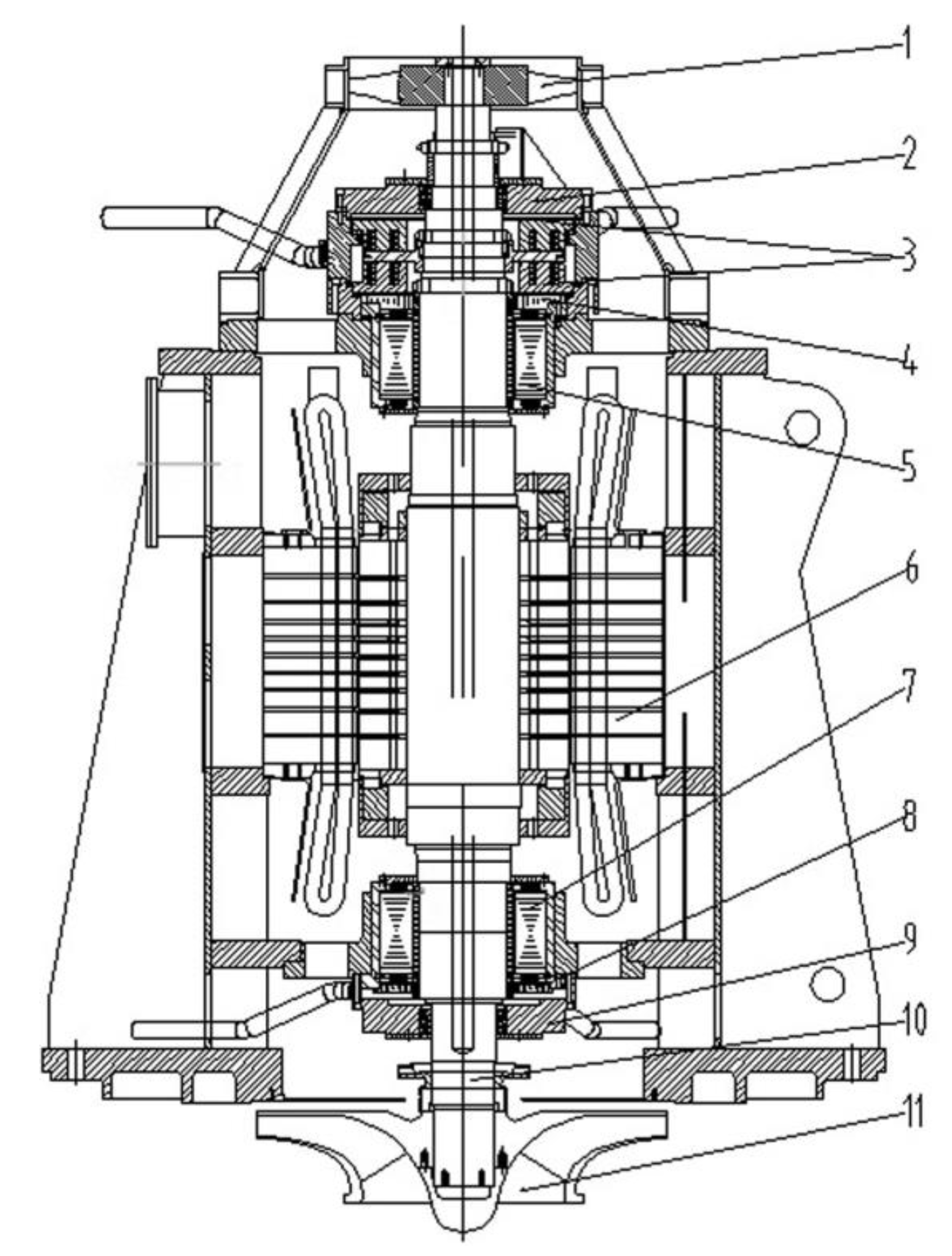
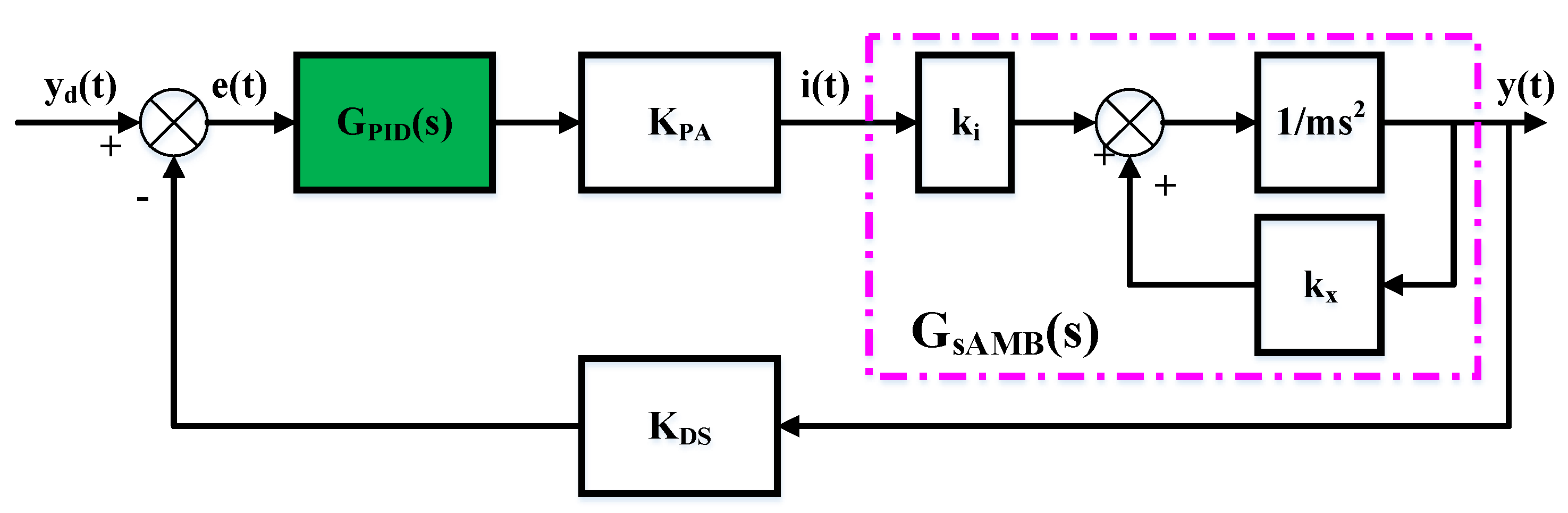
2.1. The Analysis of AMB in PHC-EP

In HTR, AMB technology is used to suspend the PHC rotor. According to the design requirements of the HTR primary loop, the PHC adopts vertical layout, and the structure of PHC-EP is shown in Figure 1, and the main parameters are shown in Table 1.
In order to analyze the AMB technology of the PHC clearly, the schematic diagram of vertical AMBs is shown in Figure 2.
In Figure 2, the axial thrust bearing is used to balance the gravity of the rotor, and the upper and lower radial AMBs are used to achieve the stability control for the four degrees of freedom (DOF) of the rotor. Generally, a rigid rotor has six degrees of freedom of motion, they are translational motion along three axes and rotation around three axes respectively [13]. However, in an AMBs, five DOFs (four radial DOFs and one DOF that refers to axial motion) are controlled by AMB, and the other DOF that rotates around its axis is controlled by a motor [3].

2.2. The Analysis of UMP in PHC-EP

As one of the key components of the PHC, AMBs have many unbalance factors that would lead to vibration. Here we can divide them into two categories: One is unbalanced centrifugal force produced by the rotor mass imbalance, or sensor runout, which comes from manufacturing inaccuracy, residual dirt, structural corrosion, or deformation of the rotor during operation; the other is UMP produced by misalignment of the geometric center between the stator and the rotor, or the circuit imbalance in motor converter, AMB power amplifier, or pole winding. In the construction of the PHC-EP, the rotor mass imbalance and sensor runout problems have been effectively solved through various means. In this paper, we analyze the mathematical mechanism of the UMP to reveal the multi-frequency vibration characteristics.
There are lots of research results on the UMP in rotating machinery. In this paper, the vibration characteristics are analyzed based on the PHC-EP rigid rotor. A cross-sectional view of the rotor at the motor position is shown in Figure 3.
Here, O ( 0 , 0 ) is the geometric center of the stator, and the fixed coordinate system OXY is established with this point as the origin of coordinates. Furthermore, O g ( x g , y g ) is the geometric center of the rotor, O m ( x m , y m ) is the rotor mass center,   O O g = r is the geometric eccentricity and O g O m = a is the mass eccentricity. Meanwhile, ω is the rotor rotational speed and θ is the initial phase of the mass center with respect to   OXY . Thus, the geometrical relationship can be expressed as
{ x m x g = a c o s θ y m y g = a s i n θ
From the electromagnetic induction principle [14], it can be known that the magnetic pole of the motor can generate the tangential force and radial force on the rotor simultaneously. Therefore, once the rotor does not rotate around the stator axis, the magnetic field of the air gap between the rotor and the magnetic pole of the motor will be asymmetric, and the radial force generated cannot be balanced with each other. Here, the analysis of UMP is carried out in combination with the three-phase induction motor with p = 1 ( p is number of pole-pairs) used in PHC-EP. According to the principle of electrical machine [12,15] and [16], the fundamental magnetic motive force (MMF) with the air gap can be expressed as:
F ( α , t ) = F 0 c o s ( ω t α )
where F 0 is the amplitude of the fundamental MMF of the excitation current of the rotor, related with the motor structure, winding turns, current, etc. The air gap expression of an arbitrary angle α shown in Figure 3 can be obtained as:
δ ( α , t ) = δ 0 r c o s ( α θ )
where δ 0 is the mean air-gap length when the rotor is centered. Therefore, the air-gap permeability can be written as Equation (4) [17]. Furthermore, it can be transformed with the theory of Fourier [18], and the first three terms are kept here and expressed as in Equation (5).
δ ( δ ) = μ 0 δ ( α ) = μ 0 δ 0 [ 1 e c o s ( α θ ) ]
δ ( δ ) = μ 0 δ 0 n = 0 e n c o s n ( α θ ) 0 + 1 c o s ( α θ ) + 2 c o s 2 ( α θ )
e = r δ 0
where e is the relative eccentricity, μ 0 is permeability of vacuum. 0 ,   1 , and 2 are the Fourier coefficients expressed in Equation (7).
{ 0 = μ 0 δ 0 1 e 2 1 = 2 μ 0 δ 0 1 e 2 ( 1 1 e 2 e ) 2 = 2 μ 0 δ 0 1 e 2 ( 1 1 e 2 e ) 2 3 = 2 μ 0 δ 0 1 e 2 ( 1 1 e 2 e ) 3
According to Equation (2) and Equation (5), the expression of the magnetic field density of air gap with α can be obtained:
B ( α , t ) = δ ( δ ) F ( α , t )
Then according to the principle of Maxwell stress integral [14], the stress over rotor surface can be obtained by decomposing the UMP along the X and Y directions.
{ F u m p x = L R 0 2 π B ( α , t ) 2 μ 0 c o s α d α F u m p y = L R 0 2 π B ( α , t ) 2 μ 0 s i n α d α
where L is the length of rotor, and R is the radius of rotor. Substituting Equation (8) into Equation (9), the calculation results can be get as shown in Equation (10).
{ F u m p x = c 0 c o s θ + c 1 cos ( 2 ω t θ ) + c 2 cos ( 2 ω t 3 θ ) F u m p y = c 0 s i n θ + c 1 sin ( 2 ω t θ ) c 2 sin ( 2 ω t 3 θ )
where c 0 , c 1 , and c 2 are the coefficients, which are calculated as expressed in Equation (11).
{ c 0 = π R L 4 μ 0 F 0 2 ( 2 0 1 + 1 2 + 2 3 )   c 1 = π R L 4 μ 0 F 0 2 ( 0 1 + 1 2 1 2 + 1 2 2 3 ) c 2 = π R L 4 μ 0 F 0 2 ( 0 3 + 1 2 1 2 )  
It can be seen that the results of the high-frequency components of the UMP are ignored in equations (10), but the rest of UMP are still complex. Fortunately, as the frequency increases, the amplitudes of the UMP are increasingly smaller, so they can be ignored in the practical calculation. However, in Equation (10), there are the constant forces with coefficient   c 0 , and this part of the force is needed to be balanced by the magnetic force produced by AMBs [19]. This is a prerequisite for system stability. The other two parts of the force with double-frequency characteristic are the main sources of the double-frequency vibration disturbance of the AMBs.

2.3. The Analysis of Multi-Frequency Vibration Characteristics

In fact, the geometrical eccentricity between the stator and the rotor is derived from two parts, one part is called static eccentricity, which is caused by the misalignment in the installation, and the other part is called dynamic eccentricity, which is caused by unbalanced force, such as the rotor mass imbalance and sensor runout [6]. Due to the complexity of high-frequency vibration analysis, the high-frequency of the UMP has been ignored in the Section 2.2, and the only double-frequency components are retained. Therefore, the analysis in this paper is based on the double-frequency vibration generated by the UMP described in Equation (10).
As the UMP exists in the traditional mechanical bearing, the constant part of the UMP will pull the rotor towards the narrowest air gap, resulting in excessive friction, friction heat and energy loss, etc. [16]. Fortunately, when the rotor is suspended by AMBs, the dynamic balance of this component force can be achieved under the action of the AMB closed-loop feedback control system [3,19]. Nevertheless, the rotor would still vibrate, which can be reflected from the rotor’s axis loci. The rest of the UMP components described in Equation (10) can be expressed as
{ F ˜ u m p x = A 2 x cos ( 2 ω t φ 2 x ) F ˜ u m p y = A 2 y sin ( 2 ω t φ 2 y )
{ A 2 x = ( c 1 c o s θ + c 2 cos 3 θ ) 2 + ( c 1 s i n θ + c 2 sin 3 θ ) 2 A 2 y = ( c 1 c o s θ c 2 sin 3 θ ) 2 + ( c 1 s i n θ c 2 sin 3 θ ) 2 { t a n φ 2 x = c 1 s i n θ + c 2 sin 3 θ c 1 c o s θ + c 2 cos 3 θ t a n φ 2 x = c 1 s i n θ c 2 sin 3 θ c 1 c o s θ c 2 cos 3 θ
Since the PHC-EP rigid rotor is with typical second-order characteristics, the nonlinear vibration of the system caused by the UMP can be calculated as
{ m x g ¨ + c x g ˙ + k x g = F ˜ u m p x m y g ¨ + c y g ˙ + k y g = F ˜ u m p y
where c is rotor damping and k is rotor stiffness. Here we can see that it is difficult to solve the equation by numerical analysis, and the implicit integration formula of the Newmark integral method [20] can be used to calculate the non-linear dynamic response of equations (14). However, in this paper, the vibration characteristics are analyzed mainly from the perspective of solution form. According to the solution method of differential equation [21], the solution of the equations (14) can be expressed as
{ x g ( t ) = C x 1 e x 1 t + C x 2 e x 2 t + C u m p x cos ( 2 ω t + φ u m p x ) y g ( t ) = C y 1 e y 1 t + C y 2 e y 2 t + C u m p y sin ( 2 ω t + φ u m p x )
where   x 1 , x 2 , y 1 ,   and   y 2 are the eigenvalues,   C x 1 , C x 2 , C u m p x , C y 1 , C y 2 , C u m p y , φ u m p x , and φ u m p y are the constants of the solution of equations (15). Since the AMB rotor system is stable operating in equilibrium point based on closed loop negative control system, the eigenvalues are located in the left half complex plane. This means the exponential terms ( C x 1 e x 1 t + C x 2 e x 2 t and   C y 1 e y 1 t + C y 2 e y 2 t ) of equations (15) are decayed over time, and the rest components of the motion can be written as
{ x g ( t ) = C u m p x cos ( 2 ω t + φ u m p x ) y g ( t ) = C u m p y sin ( 2 ω t + φ u m p x )
As described in Equation (16), the UMP eventually leads to the simple harmonic vibration with the double-frequency characteristics in the X and Y directions. In view of the actual rotor vibration components, if there is only single double-frequency vibration, the rotor's axis locus is round or oval; if there are synchronous frequency and double-frequency vibrations, the rotor's axis locus is usually “heart-shaped”; if there are several different frequency vibrations, the rotor's axis locus would become a more complex one, such as in the form of “petal type”. Figure 4 graphically describes the rotor's axis loci under these typical combinations of vibrations.
From the above analysis, it can be known that no matter which combination of vibrations, the vibrations produced by the UMP have periodic characteristics. Unfortunately, the closed-loop feedback control system based on PID algorithm has very limited effect on periodic vibration control.
However, since the PHC is the main equipment of the HTR primary loop, the PHC rotor vibration not only easily causes friction between rotor and the auxiliary bearing, which would lead to damage of the system structure, but also indirectly transfers the vibration through the base to the whole primary loop main pipeline. That is to say, these vibrations may lay significant safety hazard to the HTR. Therefore, how to effectively suppress the periodic vibrations generated by this unbalanced force has become one of the crucial technical problems to be solved urgently in the application of AMB in the PHC.

3. The Control Method for UMP

Since the constant component of the UMP can be balanced by AMB, which is achieved by the AMB closed-loop feedback control system, the control method studied here is only used to the periodic components of the UMP.
As an intelligent control method, ILC algorithm has a good self-learning ability due to the use of the system’s past information and also has unique advantages in the field of controlling repetitive problems. According to [22,23], the theory of ILC has been developed rapidly and applied successfully in many areas. In this paper, an efficient ILC algorithm is designed to suppress the double-frequency vibration generated by the UMP of the PHC-EP.

3.1. Distributed ILC Algorithm

Although there is a certain radial coupling in the radial AMBs in the design of the PHC-EP AMB control system, a distributed independent control strategy is adopted in the radial AMBs. In order to keep consistency with the original AMB control system, a distributed control scheme is also adopted in the design of the periodic vibration control. Additionally, since the UMP acts only on the rotor radial directions, the axial vibration is not considered in this paper.
Here, a single input single output (SISO) time-varying system is used to describe the plant model of a single DOF AMBs. Since a digital control system is used in actual AMBs, the discrete difference equation of a single DOF AMBs can be described as
{ x k ( t + 1 ) = A ( t ) x k ( t ) + B ( t ) u k ( t )   y k ( t )   = C ( t ) x k ( t )  
where k ϵ { 0 , 1 , 2 , } is the iterative index, t = [ 0 , 1 , 2 , , N 1 ] , N is the iterative learning step size, and is equal to the number of sampling points in the iterative learning cycle T satisfying the relationship as described in Equation (18),
T = N f s
where f s is the sampling frequency of the control system. The system control objective can be expressed as described in Equation (19).
lim k e k ( t ) = lim k [ y d ( t ) y k ( t ) ] = 0
Now we assume the system is reachable, that is, there exists a unique target input sequence u d ( t )   for the target output sequence   y d ( t ) . Thus the goal of ILC is to find the target control sequence u d ( t )   through repetitive iterations so that the actual output sequence y k ( t ) can track the target output sequence   y d ( t ) .
The solution of the state equation of the discrete system shown in Equation (17) can be described as Equation (20) [24],
x k ( t ) = Φ ( t , 0 ) x k ( 0 ) + l = 0 t 1 Φ ( t , l + 1 ) B ( l ) u k ( l ) ,   ( 1 t T )
where x k ( 0 ) is the initial state of the system.
Considering the time-varying characteristics of the system state, and the typical second-order characteristics of the PHC-EP rigid rotor, here a first order open-loop differential ILC algorithm with variable forgetting factor and variable learning gain is proposed to adapt to the changes of the system states. The structure of the distributed ILC algorithm in each direction is shown as
u j k + 1 ( t ) = ( 1 ξ j f f ( k ) ) u j k ( t ) + ξ j f f ( k ) u j 0 ( t ) + j k ( k , t ) ( e j k ( t + 1 ) e j k ( t ) )
where j ϵ { x 1 , y 1 , x 2 , y 2 } are the four radial directions of the AMBs, ξ j f f ( k ) is the forgetting factor changed with the iterations, and j k ( k , t ) is the variable differential gain changed with the iteration k and learning step t . For the convenience of subsequent algorithm analysis, ILC algorithms in four directions are unified as
u k + 1 ( t ) = ( 1 ξ f f ( k ) ) u k ( t ) + ξ f f ( k ) u 0 ( t ) + k ( k , t ) ( e k ( t + 1 ) e k ( t ) )
Combining with Equation (17) and (22), the convergence condition of the control error can be obtained as
{ | 1 ξ f f ( k ) ( k , t ) C ( t + 1 ) B ( t ) | < 1 lim k ξ f f ( k ) = 0
Here, the iterative control error of the ( k + 1 ) th sample is used to prove the convergence of the algorithm, and the analysis processed are described as follows:
Δ u k + 1 ( t ) = u d ( t ) u k + 1 ( t ) = u d ( t ) ( ( 1 ξ f f ( k ) ) u k ( t ) + ξ f f ( k ) u 0 ( t ) + k ( k , t ) ( e k ( t + 1 ) e k ( t ) ) ) = ( 1 ξ f f ( k ) ) Δ u k ( t ) + ξ f f ( k ) Δ u 0 ( t ) k ( k , t ) C ( t + 1 ) Δ x k ( t + 1 ) + k ( k , t ) C ( t ) Δ x k ( t ) = ( 1 ξ f f ( k ) ) Δ u k ( t ) + ξ f f ( k ) Δ u 0 ( t ) k ( k , t ) C ( t + 1 ) k ( k , t ) C ( t + 1 ) ( A ( t ) Δ x k ( t ) + B ( t ) Δ u k ( t ) ) + k ( k , t ) C ( t ) Δ x k ( t ) = [ 1 ξ f f ( k ) k ( k , t ) C ( t + 1 ) B ( t ) ] Δ u k ( t ) + ξ f f ( k ) Δ u 0 ( t ) + k ( k , t ) [ C ( t ) C ( t + 1 ) A ( t ) ] Δ x k ( t )
Namely,
Δ u k + 1 ( t ) = [ 1 ξ f f ( k ) k ( k , t ) C ( t + 1 ) B ( t ) ] Δ u k ( t ) + ξ f f ( k ) Δ u 0 ( t ) + k ( k , t ) [ C ( t ) C ( t + 1 ) A ( t ) ] Δ x k ( t )
We take the norm of both sides of Equation (25); it can be
Δ u k + 1 ( t ) 1 ξ f f ( k ) k ( k , t ) C ( t + 1 ) B ( t ) Δ u k ( t ) + ξ f f ( k ) Δ u 0 ( t ) + k ( k , t ) [ C ( t ) C ( t + 1 ) A ( t ) ] Δ x k ( t ) ρ Δ u k ( t ) + ξ f f ( k ) Δ u 0 ( t ) + a 1 Δ x k ( t ) ρ Δ u k ( t ) + ξ f f ( k ) Δ u 0 ( t ) + a 1 l = 0 t 1 Φ ( t , l + 1 ) B ( l ) Δ u k ( t ) ρ Δ u k ( t ) + ξ f f ( k ) Δ u 0 ( t ) + a 1 a 2 l = 0 t 1 Δ u k ( l )
where
{ ρ = 1 ξ f f ( k ) k ( k , t ) C ( t + 1 ) B ( t ) a 1 = sup 0 t T 1 k ( k , t ) [ C ( t ) C ( t + 1 ) A ( t ) ] a 2 = sup 0 t T 1 , 0 l t 1 Φ ( t , l + 1 ) B ( l )
We multiply by λ t on both sides of Equation (26), where 0 < λ < 1 , it can be
λ t Δ u k + 1 ( t ) ρ λ t Δ u k ( t ) + ξ f f ( k ) λ t Δ u 0 ( t ) + a 1 a 2 l = 0 t 1 λ t l λ l Δ u k ( l )
Based on the theory of λ norm [25], it can be
Δ u k + 1 ( t ) λ ρ ˜ Δ u k ( t ) λ + ξ f f ( k ) Δ u 0 ( t ) λ
where ρ ˜ =   ρ + a 1 a 2 λ ( 1 λ T ) 1 λ . Obviously, we can find a small λ as   ρ < 1 , to ensure   ρ ˜ < 1 . Therefore, it can be
Δ u k ( t ) λ Δ u 0 ( t ) λ 1 ρ ˜ ξ f f ( k )
Then we take the limit for both sides of Equation (30), it can be
lim k Δ u k ( t ) λ Δ u 0 ( t ) λ 1 ρ ˜ lim k ξ f f ( k ) = 0
As lim k Δ u k ( t ) λ 0 , so it can be
lim k Δ u k ( t ) λ = 0
According to equations (17) and (20)
λ t e k ( t ) C ( t ) l = 0 t 1 Φ ( t , l + 1 ) B ( l ) λ t l λ l Δ u k ( l ) a 2 a 3 λ ( 1 λ T ) 1 λ Δ u k ( t ) λ
where a 3 = sup 0 t T C ( t ) , and based on the theory of λ norm, it can be
sup 0 t T { λ t e k ( t ) } a 2 a 3 λ ( 1 λ T ) 1 λ Δ u k ( t ) λ
Combining with Equation (31), finally we can get:
lim k sup 0 t T { λ t e k ( t ) } = 0
It can be seen that under the condition of Equation (23), the system control error described in Equation (19) converges to zero in a limited time, which indicates that the first order open-loop differential ILC algorithm with variable learning gain and variable forgetting factor proposed in this paper has the convergence characteristics. Furthermore, u 0 ( t ) and ξ f f ( k ) are explained as:
(1)
u 0 ( t ) is the initial control value. In this paper,   u 0 ( t ) = 0 .
(2)
ξ f f ( k ) is mainly used to improve the stability condition of the system with too fast convergence in the process of variable gain learning. It is also a kind of robust design method, to solve the problem that the identical initial conditions cannot be satisfied completely in each iteration. We set it here as the simplest inverse proportional function of   k . Namely,
ξ f f ( k ) = 1 k
This is an empirical approach, and it can be adjusted according to the speed of actual iteration. Further,
lim k ( 1 ξ f f ( k ) ) = 1
It can be seen from Equation (21) that as the number of iterations increases, u k + 1 ( t ) is more and more dependent on the previous   u k ( t ) .
(3)
k ( k , t ) is used to solve the problem that it is lack of real-time performance as a constant learning gain used in the algorithm; we choose a comprehensive exponential function based on k and t as the differential gain to achieve fast convergence of the system. Namely,
k ( k , t ) = k B C 1 k e t N
where k B C is determined by Equation (23). Based on equations (23), (37), and (38), it can be seen that it is only necessary to determine k B C if the condition expressed in Equation (23) is satisfied. Further,
lim k k B C 1 k e t N = 0
If conservative setting method is adopted, a model-free control method can be achieved here. Further, under the condition expressed in equations (37) and (39), the control output expressed by Equation (22) can be rewritten as
lim k u k + 1 ( t ) = lim k u k ( t ) = u d ( t )
This reveals that the target output sequence u d ( t ) can be obtained through repetitive iterative learning as   k , and lim k e k ( t ) = 0 can be achieved finally.

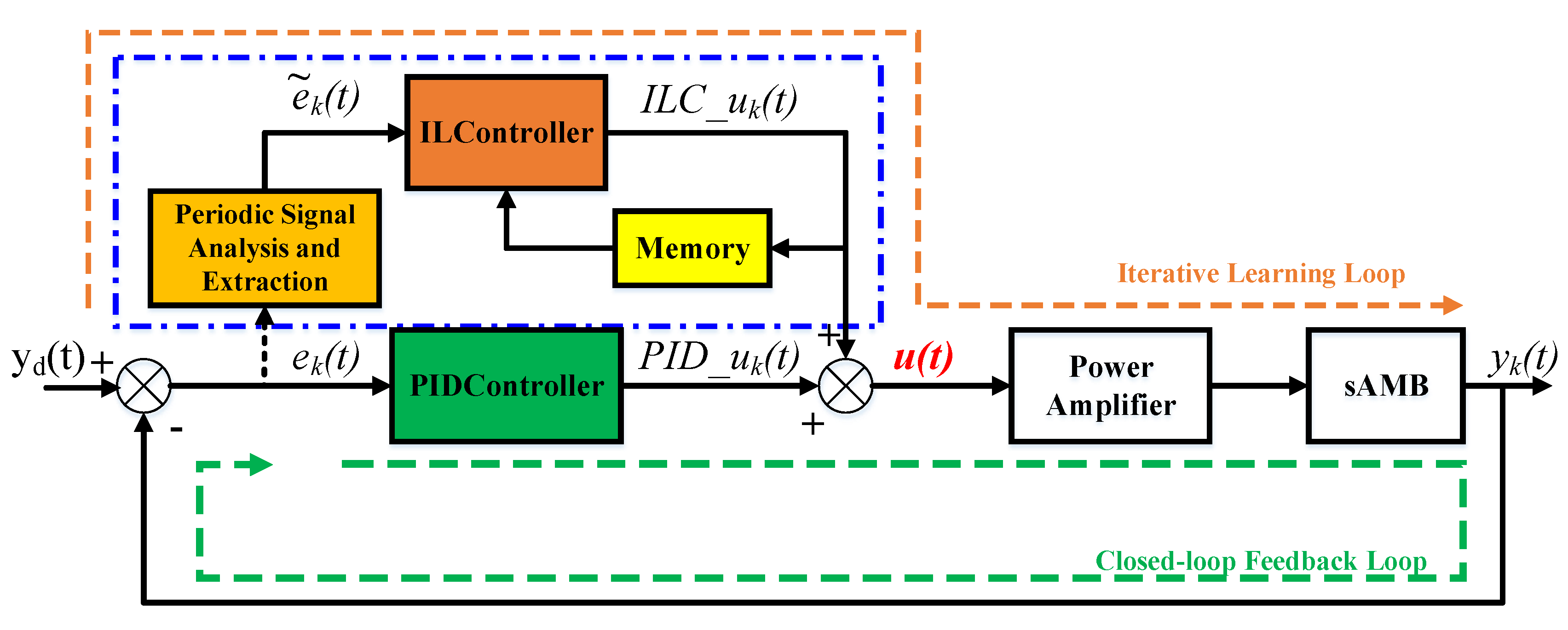
3.2. Integrated Parallel Control Scheme

The ILC designed in this paper as shown in Equation (23) belongs to open-loop control method, so it needs the original closed-loop feedback control scheme to achieve the system stability. Firstly, a SISO AMBs is taken as an example to analyze the original closed-loop feedback control system as shown in Figure 5.
In Figure 5, K P A and K D S are the power amplifier coefficient and displacement sensor coefficient of the AMBs, respectively, and they are constants while the system is designed. Additionally, k i and k x are the current coefficient and displacement coefficient of the AMBs, respectively, which are two constants related to the structure and equilibrium point after linearization. Therefore, the transfer function of the SISO AMBs can be expressed as
G s A M B ( s ) = k i m s 2 k x
Obviously, AMB is an open-loop unstable system, the closed-loop feedback loop scheme must be used to achieve the system stability control. At present, PID control algorithms are always used in actual AMBs. According to [26,27], an effective way of ILC is combined with other control methods, so the ILC in this paper is implemented in parallel with the existing closed-loop feedback system of the AMB. The final control scheme is shown in Figure 6.
From Figure 6, the actual output of the designed integrated parallel controllers is generated by both the PID controller and ILC controller and can be expressed as
u ( t ) = I L C _ u k ( t ) + P I D _ u k ( t )

3.3. Asynchronous Learning Mechanism Based on the Period of Rotation

From the above analysis, the time of a revolution of the rotor is used as the iterative learning period   T because the periodic vibration caused by UMP has double-frequency characteristics. Therefore, the speed phase detected is used as the condition to reset each iteration, which is inconsistent with the traditional iterative learning as it is reset completely to the initial states in each iteration. This kind of ILC is always called asynchronous learning mechanism in [28]. So the ILC based on asynchronous learning mechanism can be rewritten as
u k + 1 ( ( k + 1 ) T + t )                                                                                                                                         = ( 1 ξ f f ( k ) ) u k ( k T + t ) + ξ f f ( k ) u 0 ( t ) + k ( k , t ) ( e k ( k T + t + 1 ) e k ( k T + t ) )                 
Since PHC-EP is always running at the rated speed and the rotation time of the rotor is fixed, the number of sampling points ( N ) in the control system is a deterministic value during this fixed time interval. Moreover, it is necessary to perform periodic component extraction on the displacement error information at the end of each iteration, which is determined by the real-time speed phase. Extraction algorithm of double-frequency vibration component is based on discrete Fourier transform theory [29], and the extraction process can be described as follows:
(1)
The first step is to calculate the periodic component coefficients a k and b k , and expressed as
{ a k = i = 0 N 1 e k [ i ] cos ( 4 π i N ) b k = i = 0 N 1 e k [ i ] sin ( 4 π i N )
(2)
The second step is to synthesize periodic vibrations   e k ˜ [ i ] as expressed below:
e k ˜ [ i ] | N 1 i = 0 = 2 N ( a k cos ( 4 π i N ) + b k sin ( 4 π i N ) )
e k ˜ [ i ] | N 1 i = 0 = A k cos ( 4 π i N θ )
{ A k = 2 N a k 2 + b k 2 t a n θ = b k a k
In particular, this extraction method includes components of the synchronous frequency component and double-frequency to achieve effective control of periodic vibration, which has important value in practical application, especially for the AMBs where the rotor still has serious mass imbalance or sensor runout.

4. Experimental Research on Control Method

4.1. Experimental System Design

In order to verify the effectiveness of the control method, experimental studies are carried out on the AMB bench of PHC-EP. The control system in four radial directions is upgraded by the integrated distributed parallel control scheme as described in the Section 3.2, and the upgraded control system is shown in Figure 7.
In order to realize the function of the integrated distributed parallel control system, a multi-channel analog adder with limiting function is specially designed to achieve the superposition function of the parallel control outputs descried in Equation (41). The circuit of the multi-channel analog adder and its channel conformance test results are shown in Figure 8 and Figure 9.
The experimental system adopts a digital control system, which is also developed by our group. Also the ILC controller and PID controller are all developed based on TMS320F28335, which is a 32-bit floating-point DSP with the main frequency of 150MHz. Control algorithms are developed on the Code Composer Studio 8.1.0 environment. NI USB 6215 with the frequency of 10 kHz is used to gather the displacement signal of each control channel for real-time monitoring.

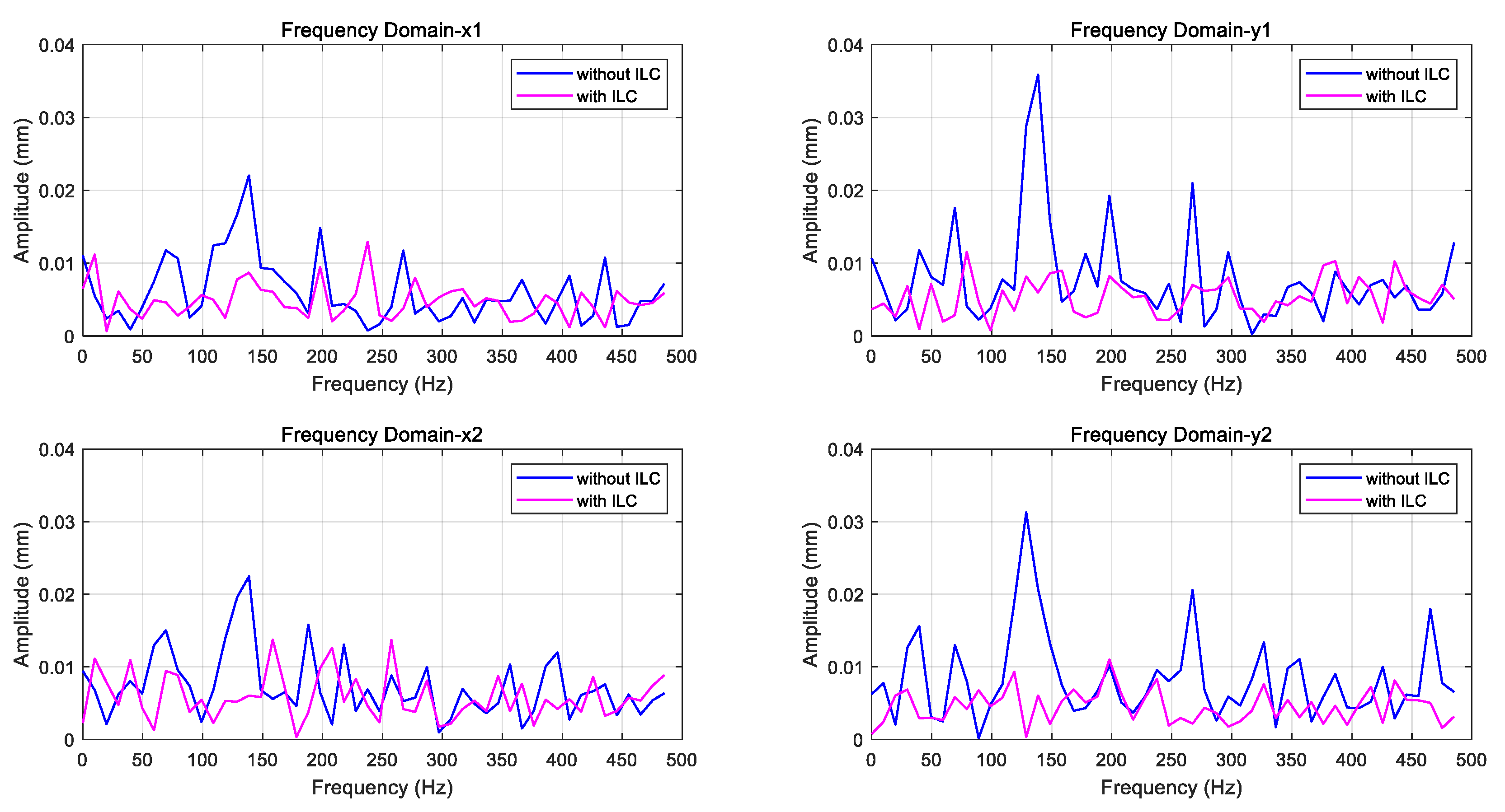
4.2. Experimental Results Analysis

According to the operation specification of the PHC-EP, the speed is steadily increased to the rated speed with 4 000   r / m ( f 66.7   Hz ) as described in Table 1, and then, we carry out the experimental researches.
Since the implementation of the ILC algorithm does not need to pay attention to the original closed-loop feedback control system parameters and considering that the AMBs has been working stably near the equilibrium point, the ILC parameters of the radial four directions are set in accordance with equations (35) and (37), and k B C = 1 is selected according to the AMB bench of PHC-EP.
In order to better illustrate the effectiveness of the control method, this paper mainly uses the comparative analysis method to study the experimental results. The vibration spectrums of the four radical directions and the rotor’s axis loci of the places’ installed displacement sensors with and without the ILC are selected as observational parameters or states. The experimental results are shown in Figure 10 and Figure 11.
From Figure 10, it can be seen that there are synchronous vibration, double-frequency; multi-frequency vibration and non-periodic vibration exist in the radial four directions, but the double-frequency vibration are the most serious as the ILC loops are not activated. However, the periodic vibrations are suppressed effectively as the ILC loops are activated, which are related to the periodic component extraction algorithm described in Equations (43), (44), and (45), because the extraction algorithm proposed in this paper can process synchronous vibration and double-frequency vibration simultaneously.
From the AMB rotor’s axis loci described in Figure 11, the axis loci are complex and in the form of “quasi heart-shaped” as the ILC loops are not activated. The reasons are that the vibrations with many frequencies are existing in the radial four directions, and they are more complex than expressed in Figure 4. However, the axis loci are eventually converged to cluster as the ILC loops are activated, which is due to the fact that there are only some non-periodic vibrations left.
It can be seen that periodic vibrations are effectively suppressed by activating the ILC loops from Figure 10 and Figure 11. In other words, the UMP caused by the misalignment of the geometric center between the rotor and the stator can be effectively controlled by the control method designed in this paper.

5. Conclusions

The synchronous vibration caused by the rotor mass imbalance or sensor runout is often dominant in the actual vibration control of AMB system, but double-frequency vibration and multi-frequency vibration caused by UMP or other reasons cannot be ignored. Due to the significant double-frequency vibration disturbance existing in the PHC-EP, we analyzed the mechanisms of UMP and the double-frequency vibration and designed the control method to suppress double-frequency vibration. Moreover, we took into account the control of synchronous vibration. Therefore, it can be said that the control method developed in this paper can suppress the synchronous vibration and double-frequency vibration and provide technical support for safe and stable operation of PHC-EP. In particular, the method proposed in this paper also can be further extended to the vibration control of AMBs in other fields.

Author Contributions

Methodology, Y.Z. (Yangbo Zheng), N.M., and Z.S. (Zhe Sun); writing—original draft preparation, Y.Z. (Yangbo Zheng); guidance and editing, Y.Z. (Yangbo Zheng), N.M., Z.S. (Zhe Sun), Y.Z. (Yan Zhou), and Z.S. (Zhengang Shi).

Funding

This work is supported by National Science and Technology Major Project (No. 2019ZX06903019) of China.

Conflicts of Interest

The authors declare no conflict of interest.

References

  1. Zhang, Z.; Dong, Y.; Li, F.; Zhang, Y.; Wang, H.; Huang, X.; Li, H.; Liu, B.; Wu, X.; Wang, H.; et al. The Shandong Shidao Bay 200 MWe High-Temperature Gas-Cooled Reactor Pebble-Bed Module (HTR-PM) Demonstration Power Plant: An Engineering and Technological Innovation. Engineering 2016, 2, 112–118. [Google Scholar] [CrossRef]
  2. Dong, Z. Saturated Adaptive Output-Feedback Power-Level Control for Modular High Temperature Gas-Cooled Reactors. Energies 2014, 7, 7620–7639. [Google Scholar] [CrossRef] [Green Version]
  3. Maslen, E.; Schweitzer, G. Magnetic Bearings: Theory, Design, and Application to Rotating Machinery; Springer: Berlin, Germany, 2009. [Google Scholar]
  4. Yang, G.; Shi, Z.; Mo, N.; Zhao, L. Research on Active Magnetic Bearing Applied in Chinese Modular High-temperature Gas-cooled Reactor. Prog. Nucl. Energy 2014, 77, 352–360. [Google Scholar] [CrossRef]
  5. Zhang, G.; Wu, J.; Hao, L. Fast Calculation Model and Theoretical Analysis of Rotor Unbalanced Magnetic Pull for Inter-Turn Short Circuit of Field Windings of Non-Salient Pole Generators. Energies 2017, 10, 732. [Google Scholar] [CrossRef]
  6. Ruf, A.; Schroder, M.; Putri, A.K.; Konrad, R.; Franck, D.; Hameyer, K. Analysis and Determination of Mechanical Bearing Load Caused by Unbalanced Magnetic Pull. COMPEL 2016, 35, 728–743. [Google Scholar] [CrossRef]
  7. Xu, X.; Han, Q.; Chu, F. Nonlinear Vibration of a Generator Rotor with Unbalanced Magnetic Pull considering Both Dynamic and Static Eccentricities. Arch. Appl. Mech. 2016, 86, 1521–1536. [Google Scholar] [CrossRef]
  8. Zhang, A.; Bai, Y.; Yang, B.; Li, H. Analysis of Nonlinear Vibration in Permanent Magnet Synchronous Motors under Unbalanced Magnetic Pull. Appl. Sci. 2018, 8, 113. [Google Scholar] [CrossRef]
  9. Dorrell, D.; Kayani, O. Measurement and Calculation of Unbalanced Magnetic Pull in Wound Rotor Induction Machine. IEEE Trans. Magn. 2014, 50, 1–4. [Google Scholar] [CrossRef]
  10. Han, B.; Zheng, S.; Liu, X. Unbalanced Magnetic Pull Effect on Stiffness Models of Active Magnetic Bearing Due to Rotor Eccentricity in Brushless DC Motor Using Finite Element Method. Math. Probl. Eng. 2013, 2013, 1–10. [Google Scholar] [CrossRef]
  11. Di, C.; Petrov, I.; Pyrhönen, J.J.; Bao, X. Unbalanced Magnetic Pull Compensation with Active Magnetic Bearings in a 2 MW High-Speed Induction Machine by FEM. IEEE Trans. Magn. 2018, 54, 1–13. [Google Scholar] [CrossRef]
  12. Yang, G.; Shi, Z.; Mo, N. Technical Design and Engineering Prototype Experiment of Active Magnetic Bearing for Helium Blower of HTR-PM. Ann. Nucl. Energy 2014, 71, 103–110. [Google Scholar] [CrossRef]
  13. Dimarogonas, A.D.; Paipetis, S.A.; Chondros, T.G. Analytical Methods in Rotor Dynamics; Springer: Berlin, Germany, 2013. [Google Scholar]
  14. Krause, P.; Wasynczuk, O.; Pekarek, S. Electromechanical Motion Devices, 2nd ed.; John Wiley & Sons: Haboken, NJ, USA, 2012. [Google Scholar]
  15. Gerling, D. Electrical Machines and Drives: Mathematical Fundamentals of Machine Topology; Springer: Berlin, Germany, 2012. [Google Scholar]
  16. Guo, D.; Chu, F.; Chen, D. The unbalanced magnetic pull and its effects on vibration in a three-phase generator with eccentric rotor. J. Sound Vib. 2002, 254, 297–312. [Google Scholar] [CrossRef]
  17. Sen, P. Principles of Electric Machines and Power Electronics, 3rd ed.; John Wiley and Sons: Hoboken, NJ, USA, 2014. [Google Scholar]
  18. Howell, K. Principles of Fourier Analysis, 2nd ed.; Textbooks in Mathematics; CRC Press: Boca Raton, FL, USA, 2016; pp. 76–77. [Google Scholar]
  19. Schweitzer, G. Magnetic Bearings for Vibration Control; Technical Report No. 86-30185; NASA: Washington, DC, USA, 2014.
  20. Newmark, N. A method of computation for structural dynamics. J. Eng. Mech. Div. Am. Soc. Civ. Eng. 1959, 85, 67–94. [Google Scholar]
  21. Sal, K. ; World Public Library Association Author Community. Complex Roots of the Characteristic Equations 2 Differential Equations Series; Khan Academy: Mountain View, CA, USA, 2014. [Google Scholar]
  22. Xu, J.; Xu, Y. Linear and Nonlinear Iterative Learning Control; Springer: Berlin, Germany, 2003. [Google Scholar]
  23. Owens, D. Iterative Learning Control; Springer: Berlin, Germany, 2016. [Google Scholar]
  24. Rabbath, C.; Léchevin, N. Discrete-Time Control System Design with Applications; Springer: Berlin, Germany, 2014. [Google Scholar]
  25. Saff, E.; Arthur, D. Fundamentals of Matrix Analysis with Applications; John Wiley & Sons: Hoboken, NJ, USA, 2015. [Google Scholar]
  26. Maeda, G.; Manchester, I.; Rye, D. Combined ILC and Disturbance Observer for the Rejection of Near-Repetitive Disturbances with Application to Excavation. IEEE Trans. Control Syst. Technol. 2015, 23, 1754–1769. [Google Scholar] [CrossRef]
  27. Zundert, J.; Oomen, T. On Optimal Feedforward and ILC: The Role of Feedback for Optimal Performance and Inferential Control. IFAC PapersOnLine 2017, 50, 6093–6098. [Google Scholar]
  28. Xu, J.; Panda, S.; Lee, T. Real-Time Iterative Learning Control: Design and Applications; Springer: Berlin, Germany, 2009. [Google Scholar]
  29. Sundararajan, D. The Discrete Fourier Transform Theory, Algorithms and Applications; World Scientific: Singapore, 2001. [Google Scholar]
Figure 1. The structure of primary helium circulator (PHC) engineering prototype (PHC-EP) [12]. 1. Cooling fan; 2. upper auxiliary bearing; 3. axial thrust active magnetic bearing (AMB); 4. upper displacement sensor; 5. upper radial AMB; 6. asynchronous motor; 7. lower radial AMB; 8. lower displacement sensor; 9. lower auxiliary bearing; 10. rotor; 11. Wheel.
Energies 12 03682 g001
Figure 2. The schematic diagram of vertical AMBs.
Energies 12 03682 g002
Figure 3. The geometric center misalignment model between the stator and the rotor.
Energies 12 03682 g003
Figure 4. Several rotor's axis loci under typical combinations of vibrations.
Energies 12 03682 g004
Figure 5. A SISO closed-loop feedback control system for the single DOF AMBs.
Energies 12 03682 g005
Figure 6. The parallel control system for UMP of the FHC AMB.
Energies 12 03682 g006
Figure 7. The integrated parallel control system of four radial directions in the AMB bench of PHC-EP.
Energies 12 03682 g007
Figure 8. The circuit of the multi-channel analog adder with limiting function.
Energies 12 03682 g008
Figure 9. The conformance test results of the multi-channel analog adder.
Energies 12 03682 g009
Figure 10. The vibration spectrums of the four radical directions with and without the ILC.
Energies 12 03682 g010
Figure 11. The AMB rotor’s axis loci of the places’ installed displacement sensors with and without the ILC.
Energies 12 03682 g011
Table 1. The main parameters of PHC-EP.
ParameterValue
Rotor mass with impeller4 000 kg
Rated speed4 000   r / m ( f 66.7   Hz )
Motor TypeThree phase induction ( p = 1 )
AMB control methodDistributed control
Operation modeConstant speed

