Igniting Soaring Droplets of Promising Fuel Slurries
by
 ,
,
Alexander Bogomolov
1,2,* ,
,
Timur Valiullin
3,
Ksenia Vershinina
3,
Sergey Shevyrev
1 and
Nikita Shlegel
3 1
T.F. Gorbachev Kuzbass State Technical University, Kemerovo 650000, Russia
2
Institute of Thermophysics Siberian Branch, Russian Academy of Sciences, Novosibirsk 630090, Russia
3
National Research Tomsk Polytechnic University, Tomsk 634050, Russia
*
Author to whom correspondence should be addressed.
Energies 2019, 12(2), 208; https://doi.org/10.3390/en12020208
Submission received: 24 November 2018
/
Revised: 28 December 2018
/
Accepted: 31 December 2018
/
Published: 10 January 2019
(This article belongs to the Special Issue Sustainability of Fossil Fuels)
Abstract
:High rates of environmental pollution by boilers and thermal power plants burning coal of different grades are the main reason for active research in the world aimed at the development of alternative fuels. The solution to the formulated problem acceptable in terms of environmental, technical and economic criteria is the creation of composite slurry fuels with the use of fine coal or coal processing and enrichment waste, water of different quality, and oil sludge additive. This study considers modern technologies of burning slurry fuels as well as perspective research methods of the corresponding processes. A model combustion chamber is developed for the adequate study of ignition processes. The calculation of the basic geometric dimensions is presented. The necessity of manufacturing the combustion chamber in the form of an object of complex geometry is substantiated. With its use, several typical modes of slurry fuel ignition are determined. Principal differences of ignition conditions of a single droplet and group of fuel droplets are shown. Typical vortex structures at the fuel spray injection are shown. A comparison with the trajectories of fuel aerosol droplets in real combustion chambers used for the combustion of slurry fuels is undertaken.
1. Introduction
1.1. Reasons for the Increased Interest in Water-Containing Slurry Fuels
Water-containing slurry fuels based on fine coal or coal processing waste are called coal-water slurry (CWS), or composite liquid fuel (CLF). Their prospects were justified more than 40 years ago. In recent years, in the world scientific community, there have been more and more arguments in favor of the active use of water-containing slurry fuel, since it could serve to solve a number of global problems.
In particular, the main attractiveness of CLF in comparison with traditional energy resources (gas, coal, and oil) derives from the following essential advantages (based on the analysis of the research results [1,2,3,4,5,6,7,8,9,10,11]):
- (i)
- cost-effectiveness of CLF; compared to fuel oil and coal, the cost of 1 ton of CLF is 1.5–2.5 times lower; operating costs for storage, transportation and combustion are 20–30% lower;
- (ii)
- due to almost complete burnout of coal particles in CLF, gaseous anthropogenic emissions into the atmosphere are minimal and comparable to emissions from gas combustion;
- (iii)
- in terms of technological effectiveness, CLF is fire- and explosion-proof; it can be stored at a wide temperature range; slagging is reduced; there is no dependence on the properties and origin of the CLF components;
- (iv)
- CLF can be used as primary and additional fuel in all operating conditions regardless of the region; virtually any coal can be used to prepare CLF;
- (v)
- among the main combustible components of CLF, in addition to fine coal, there may be numerous wastes of coal enrichment and oil refinement; in this case, it is possible to dispose of large amounts of these wastes, to release the occupied territory, and to reduce the consumption of fossil fuels for producing thermal and electric energy.
At the same time, it is worth noting the main limitations that constrain the active use of CLF technologies [1,2,3,4,5,6,7,8,9,10,11]:
- (i)
- moisture, which can make up to 40% of CLF, is a ballast, and part of the energy from fuel combustion is spent on the phase transition of water from liquid to gaseous state;
- (ii)
- typical CLF obtained on most units (at various technologies) retains stability (does not stratify) only for 30–70 h. Modern equipment allows increasing this parameter up to 10–15 days, and even up to a year without the use of additives-stabilizers. Limited stability forces the use of additives-plasticizer or special processing methods when it is necessary to increase the CLF shelf life, which obviously increases the fuel cost. The way out of this situation is to prepare CLF immediately before combustion. This approach provides a CLF daily supply reserve in the immediate vicinity of the consumer. The main fuel supply in this case is provided by the initial coal reserves;
- (iii)
- high abrasive wear of the injectors took place at the first stages of CLF application. For example, in Russia, China, India, Japan and Poland the first nozzles served no more than 30–40 h. In modern conditions, these issues have been resolved up to the manufacturing of serial burners for CLF.
Each of these restrictions is leveled in the process of CLF preparation by adding various additives, modifying combustion chambers compared to coal and fuel oil, and adapting technologies. It is believed traditionally that, unfortunately, the technologies of CLF burning have low efficiency, despite a large number of studies (in particular, [12,13]) on the CLF ignition mechanism, possible modes and effects.
1.2. Modern Technology of Composite Liquid Fuel (CLF) Combustion
The main ways of CLF combustion are [1,2,3] burning in flame (chamber) and in a fluidized bed. Flame burning is the main method, especially in boilers of medium and high power. The geometry of the boilers, as a rule, allows the torch to be organized inside the combustion chamber so that the coal particles that make up the CLF could completely burn out. From the practice of CLF burning it may be inferred that fuel ignition begins in a small vicinity of the nozzle section, which feeds it into the combustion chamber. The disadvantages of the method include rather high requirements to the burner device of the boiler (nozzle).
At CLF burning in the fluidized bed, the fuel jet is fed to the heated layer of inert material. Droplets of CLF are almost instantly ignited when they fall in the fluidized bed. The undoubted advantages of this method of combustion are relative ease of implementation in boilers of small capacity, a fairly large range of boiler capacity control (without loss of efficiency), and low requirements to the quality of the fuel supplied. The disadvantages include the capital intensity of fluidized bed organization in boilers of medium and high power, especially in the case of reconstruction of the latter.
When burning CLF in a fluidized bed, there are technological solutions for implementing the mode of slurry fuel gasification (pyrolysis), for which CLF is an ideal raw material. In this case, the combustion is carried out in two stages: gasification and direct combustion of the obtained gases. Depending on the technological features it is possible to combine the combustion methods. Synthesis gas obtained at the gasification stage increases the CLF combustion stability. The disadvantage of the method today is the lack of commercially available boilers. This is one of the reasons for the development of a large group of different methods for studying the processes of CLF ignition, as well as different reproducible conditions for the study of the relevant processes.
1.3. Limitations of Modern Methods of Investigation of CLF Ignition and Combustion
It is possible to distinguish the following main methods of experimental studies of ignition and combustion of droplets of slurry fuels [12]: on a heated substrate or any surface (to reproduce the layer combustion, for example, on stoker grates and walls of combustion chambers); in the flow of heated air using different holders (rods, wires, thermocouple junctions, etc.); and when placing CLF droplets into the heated airflow. Each of these research methods is somewhat far from the technologies described in Section 1.2. Therefore, the task of developing the experimental technique taking into account the real features of advanced combustion technologies for promising CLF is relevant.
The aim of this work is to design a model combustion chamber for recording the limiting conditions, the main characteristics of the ignition and combustion processes, as well as the trajectories of the slurry fuel droplets in conditions close to real combustion technologies.
2. Experimental Setup and Methods
2.1. Typical Industrial Layouts of Units for CLF Combustion
To date, a fairly large number of experimental setups and experimental-industrial units used for burning fuel slurries have been developed; for example, in China, there are more than 90 steam and power plants using CLF. Among the most common Russian plants burning slurry fuels are prismatic (straight-through) elongated furnace chambers of hot water and steam boilers without significant modifications, used for direct combustion of pulverized coal or fuel oil. As a rule, they are based on the principle of flame burning by fine-dispersed fuel spray through burners or nozzles [1,2,3,4,5,6,7,8,9,10]. For example, the boiler (TPE-214) of Novosibirsk thermal power plant (Russia) was operated at burning of large volumes of CWS (over 350 × 103 m3), implemented in conjunction with the technical project of the coal pipeline (262 km) “Belovo-Novosibirsk” (Russia, from 1989 to 1997) [8]. This project was carried out on the basis of industrial research into the preparation and combustion of CWS at Belovskaya thermal power plant (Russia, from 1986 to 1987) on the basis of boilers PC-40-1 with steam capacity of 640 t/h, as well as TP-35 (Figure 1) of Min-Kush thermal power plant based on Kavak brown coal (Kyrgyzstan) [1,8].
The team of the Institute of Thermophysics (Siberian Branch of the Russian Academy of Sciences) conducted thermal calculations and changed the design of the low power boiler (KE-10-14C) for CWS combustion. For this boiler, the vortex combustion mode was used (Figure 2).
It is known that the combustion of fuel slurries based on solid (coal, coal processing waste) and liquid (water, waste oils, etc.) components is accompanied by an increase in the size of the ignition zone and a decrease in the temperature level due to the presence of liquid inert ballast. In this regard, there was a gradual transition to the vortex method of CLF burning (due to the angular circular swirl) as the most efficient combustion with the longest period of cyclicity of the soaring of fuel droplets in the reaction zone and high combustion efficiency.
For furnaces of direct-flow boiler (P-56GM) and drum boiler (BKZ-75-39FB), the tangential arrangement of burners and various forms of air blowing were applied, providing a vortex flow of combustion products and stable combustion of CWS [3].
In turn, the gas and fuel oil boiler (DKVr 6.5/13GFO) was additionally equipped with muffle (cyclone) vortex furnace extensions. They were used for pre-ignition and flame combustion of fine-sprayed fuel slurry with its subsequent burnout in the main furnace of the boiler [4]. For the reconstructed boiler DKVr-20-13 (at a transition from the layer burning of coal to the slurry one) the vortex combustion of CLF was numerically studied using the ANSYS Fluent 12 software [5].
The study [6] considered in detail the issues of modernization of steam and hot water boilers with installing cyclone furnace extensions operating on traditional fuels: coal, gas and fuel oil (Figure 3).
The study [7,8] presents the results of designing an experimental setup (Figure 4) for CLF burning. The stable CLF ignition for this furnace was carried out in the temperature range of 600–700 °C, and the temperature of the gases at the outlet of the cyclone furnace extension was 1090–1160 °C.
Studies [9,10] present the results of numerical calculations of coal-water fuel combustion in the adiabatic vortex combustion chamber obtained with ANSYS FLUENT software. These mathematical calculations to determine the optimal modes of combustion of CWS can improve the design accuracy of various boilers.
2.2. Typical Diagrams of Experimental Setups for Studying CLF Combustion
Efficient CLF combustion at thermal power plants or small boilers, as well as achieving the maximum efficiency of the power plant, is associated with the optimal organization of fuel ignition in the combustion chamber, stabilization of the flame combustion and achievement of the set temperature level. As a rule, it depends on the correctly chosen physical parameters (Tgmin is minimal ignition temperature, τd is the ignition delay time, τc is the time of complete combustion, Tdmax is the maximum temperature at the drop center during heating) for the relevant design calculations of furnace chambers. This requires a series of experimental studies on the combustion initiation of various CLF and the necessary conditions for their development.
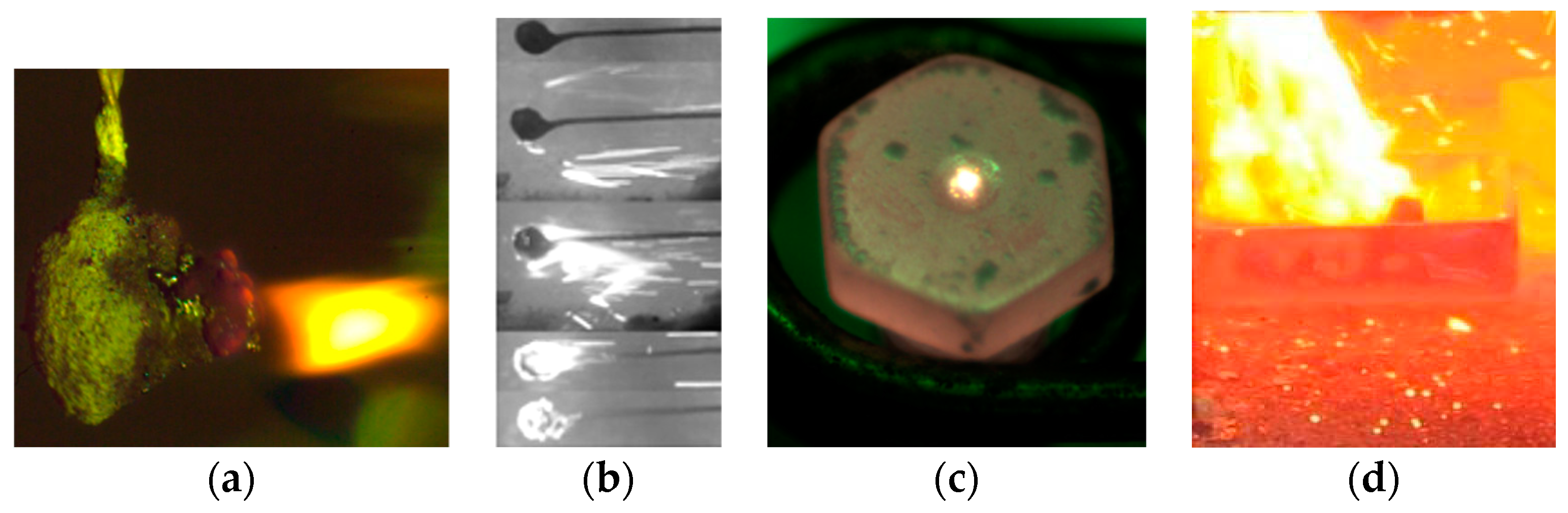
From the analysis of world practice on the study of combustion initiation of slurry fuel droplets, it should be noted that the most well-known methods are [11,12]. It is believed that the most widespread is the experimental approach, implemented by suspending a single fuel droplet on the thermocouple junction, its further placing in a heated medium (heated air, combustion products, their mixture) and recording the temperature change of the droplet (Figure 5a,b). In turn, holders made of other materials (thin metal wire, quartz thread, ceramic rod) are also often used to register fuel ignition characteristics’ parameters [13,14]. There are methods for studying ignition and combustion of CLF on a hot surface (conductive heating) [15] or in a muffle furnace (radiant heating [16]) (Figure 5c,d). In rare cases, local energy sources heated to a certain temperature (metal disks, etc.), laser pulse (for gasification), as well as spark discharge energy are used.
All the known aforementioned experimental approaches are far from the real combustion processes of thermal power plants because all of them use contact with the heated surface. Often holders lead to changes in the heat transfer conditions in the suspended fuel droplet [13,14]. One may observe processes of the heat sink from the droplet to the holder and an additional energy flow through the holder to it. These heat transfer processes are different from real conditions. As for experiments with fuel droplets freely falling through a cylindrical channel of heated air, there are restrictions associated with a small residence time of the fuel droplet in the combustion chamber (a cylindrical channel of limited length is used, see Figure 6a [17,18]). As noted above, the CLF burnout requires a long residence time of fuel droplets in the furnace space, i.e., directly in the active combustion zone.
The study of CLF ignition and combustion in these thermal power plants (large and small boilers) is difficult and limited. This is due to rather high rates of physical and chemical processes, occurring in the boiler furnace, and the impossibility of visual recording of combustion and ignition of fuel droplets in the entire volume of the core zone (Figure 6b). Individual viewing windows allow monitoring of CLF combustion processes in a narrow region (Figure 6c).
In this regard, it is advisable to develop a model combustion chamber, which would allow, on the one hand, bringing the conditions of fuel ignition and combustion to the furnaces of real boilers, and, on the other hand, visualizing these processes for soaring CLF droplets in a swirling flow of heated air with their direct video recording in real time. It is expedient to develop and manufacture a model combustion chamber from optically transparent quartz glass based on the results of calculations of geometric dimensions.
2.3. Designing the Model Combustion Chamber
In the study of the characteristics of ignition and combustion of soaring CLF droplets, in contrast to the stationary suspended droplets [11,12,13,14], the necessary parameters for the soaring of a droplet of the fuel composition were estimated. The aim of the evaluation was to determine the geometric dimensions of the expanding part of the quartz tube (with conical inlet and outlet channels), where the droplet would be ignited by the heated air flow. A model cone-shaped combustion chamber has been developed as a promising design (in terms of manufacturing complexity, placement in the laboratory and compliance with the conditions of fuel combustion at TPP). This design allows keeping the drop in the given range of heights by changing air flow pressure (due to the pressure difference over the chamber height) in the vertical direction, and, thus, changing the residence time of the fuel droplet in the combustion core. The initial data for the calculation are presented in Table 1.
The geometric dimensions of the chamber are calculated by the method of determining the soaring of a single droplet, which assumes the equality of forces of aerodynamic drag of the droplets and the gravitational forces in the ascending air flow.
When calculating the conditions of CLF droplet soaring, the following were assumed:
- 1
- The coefficient of droplet sphericity (spherical shape factor) φ = 0.73 [19].
- 2
- Droplet motion in the vertical direction in the range h = 0–120 mm (height of the calculated cone-shaped chamber).
- 3
- Properties of the component composition of CLF (density, ash, etc.) are subject to the additivity rule, and they can be determined using the relevant properties of the components.
The calculation method for droplet soaring is identical [20]. The air flow rate along the channel section, at which a single drop passes into a soaring state, is the rate of soaring [21]. It corresponds to the beginning of the destruction of the monodisperse soaring layer. At that,
where ε is the porosity (relative fraction of volume not filled with solid phase).
is the bulk density, and is the body density (drop).
ε = 1,
The soaring rate may be determined by Equations [20]:
where Revit is the Reynolds criterion, ϖvit is the rate of soaring, m/s; dd is the drop diameter, m; , are the density (kg/m3) and dynamic viscosity coefficient (Pa·s) of air; and Ar is the Archimedes criterion.
Density and dynamic coefficient of air viscosity (Table 2) are taken at a temperature of 823 K [22].
Archimedes’ criterion is calculated by the expression [20]:
where is the kinematic coefficient of the medium viscosity, m2/s; and is the dynamic coefficient of the medium viscosity, Pa·s.
Droplet size (equivalent diameter):
Considering the deviation from the spherical shape the drop size will be [19]:
To calculate the Archimedes’ criterion, it is necessary to determine the density of the CLF droplet. According to the reference data [23,24], the density of coal dust in the composition of CLF is 1700 kg/m3 (water content of the initial drop is ≈43.5%).
The density of CLF droplet in the initial state:
In the future, with the known elemental composition of the used solid fuel, the droplet density is specified according to [25]:
where is the density of the organic mass of the fuel; Cp, is the percentage of carbon and hydrogen in the fuel; and is the ash content per dry mass of fuel.
The criterion of Archimedes for air temperature of 823 K:
Reynolds criterion:
Soaring rate:
High pressure vortex fan Leister Robust provides the maximum air flow rate Vv = 1200 L/min at 293 K, which corresponds to the air velocity of 4–5 m/s in the channel with a diameter of 80 mm.
Mass air flow rate:
Air velocity in the channel:
When air temperature in the channel is 823 K, considering its density of 0.43 g/L, the mass air flow rate:
The air velocity in the channel with a diameter of 80 mm is:
Thus, the required slurry velocity is provided, and the CLF drop can move vertically in the chamber along the expanding part of the cone (Figure 7). In the calculation it was assumed that the smaller diameter of the cone corresponds to the diameter of the quartz tube. The maximum height of the cone will take 120 mm (due to the limitations of the size of the experimental stand). It was believed that the droplet soaring rate of 6.98 m/s corresponds to the region with a smaller cone diameter (80 mm).
Let us consider the final state of the droplet (to determine the angle of the cone opening)—complete burnout of organic mass with forming the ash envelope. For this intermediate state of the droplet, its diameter (dd) corresponds to 1.095 mm (model of the retained ash envelope [19]). Ash content (Ad) of the initial drop of CLF is 25%.
Ash envelope density:
The ash envelope density in a droplet with a diameter of 1.095 mm will be:
where is the true ash density (in the range of 2100–2400 for Kuznetsk coals) [26].
The Archimedes’ criterion:
Reynolds criterion:
Soaring rate:
Cone diameter:
At this rate and air flow rate of 0.0588 m3/s the diameter of the cone is:
Consequently, the larger diameter of the cone is 137 mm. The height of the cone was taken earlier as 120 mm. Thus, the opening angle of the cone is about 24 degrees (Figure 7).
Due to technological limitations for casting the cone-shaped chamber from transparent optical quartz glass, the dimensions of the real combustion chamber have been changed (Figure 7b). As a result, the large diameter of the cone has almost doubled (258 mm). The dimensions of the input and output channels and the cone opening angle remain unchanged. To control the temperature in the combustion chamber by chromel-aluminum thermocouple, as well as the input and discharge of CLF drops, there are two technological holes with a diameter of 11 mm in its side part. The chamber is made with a total height of 325 mm. The volume of the combustion chamber is 6 L. This allowed expanding the limits of permissible rates of soaring of CLF droplets (for a combination of a single, small group and a flow of droplets).
3. Materials
The fuels were prepared on the basis of several different components, both solid and liquid. In this study, low-grade solid fuel (lignite or lignite) and wet coal flotation waste (filter cake) were considered as the main components. The main properties of all components used are given in Table 3 and Table 4. Proximate and ultimate analysis was carried out in accordance with standard procedures [27]. Below, the compositions of specific fuels are given either directly in the figures or in the explanatory tables.
The choice of components is due to the fact that in this study it was necessary to test several CLF with different flammability. Figure 8 illustrates the characteristic differences in the ignition delay time for several fuel compositions. The data in Figure 8 obtained by burning fuel droplets using the designed combustion chamber (Figure 7).
The initiation of burning of CLF compositions based on brown coal, water and oil components occurs at lesser ambient temperatures than that of CLF based on wastes of enrichment of filter-cake “T” and “K” (from the coal-washing plant of the Kemerovo region, Russia) and used turbine oil. The properties are presented in Table 1 and Table 2. The filter-cakes “T” and “K” had a moisture content of 43.5% and 39.1%, respectively.
An important role is played by the content of the oil component in the fuel and the minimum temperature of their ignition. The ignition temperature of fuel oil is about 513 K, which is higher relative to other liquid combustible impurities of CLF, for example, used turbine (466 K) and used compressor (502 K) oils.
Figure 8a shows that for the composition of CLF based on cake “T” and used turbine oil, the ignition delay times are less than 1 s than for the fuel mixture based on brown coal, water and fuel oil. In addition, the determining factor is the change in the initial droplet size, which affects the ignition delay times Figure 1b. If the CLF droplet size is Rd ≈ 0.4 mm, for the two compositions of CLF with used oil there is an identical ignition delay time of about 4.2 s within the limits of random errors. Furthermore, for the composition of cake “T” of 90% and used turbine oil of 10% there is a smooth increase in ignition delay time than for compositions with brown coal. This is most likely due to the lower moisture content in the cake “T” (about 35%). Thus, preliminary tests (Figure 8) made it possible to determine the composition of waste-derived fuel slurries of interest for further studies using different heating approaches.
4. Results and Discussion
4.1. Advantages of the Model Combustion Chamber
To study the ignition characteristics of the soaring CLF droplets, an experimental setup has been developed; its scheme is shown in Figure 9. The flow of heated air pumped by the compressor was formed in the model combustion chamber. Then a CLF droplet from a supply and discharge device was placed in the combustion chamber. To spray the flow of the fuel slurry into the combustion chamber, a T-shaped mixer was used; the compressed air was supplied in one of its channels, and slurry was fed in the second channel. The investigated processes of ignition and combustion of soaring droplets of CLF were registered with the use of high-speed video camera.
The configuration of the combustion chamber allows, on the one hand, approaching the conditions of the droplet soaring in real combustion chambers, and, on the other hand, visualizing the ignition processes, i.e., continuously monitoring the soaring droplets. This is achieved by the transparency of the combustion chamber, made of heat-resistant quartz glass.
4.2. Modes of Ignition and Combustion of Slurry Fuels
In experiments with the flow of soaring CLF droplets, as well as with a single droplet, several ignition modes have been recorded. They can be divided into four modes (Figure 10a). These are characterized by characteristic trajectories of motion (mainly ellipsoidal or arbitrary), directed along the heated air motion in the combustion volume. The soaring CLF flow represents the droplets of different dispersiveness with irregular shape and different weight. Consequently, each CLF droplet has different evaporation time of moisture and flammable liquid, when interacting with hot air and in chemical reactions.
In the first mode, the fuel droplet was ignited in the upper part of the combustion chamber. If the droplet fell and was ignited directly on the metal grid at the bottom of the chamber, these conditions corresponded to the second mode. It should be noted that in the second mode, the droplet after ignition and some period of combustion on the grid changed to the soaring mode. The third and fourth modes were characterized by direct soaring of CLF droplets in the heated air flow. They differ by different areas of ignition. The third ignition mode is realized closer to the wall (along the cone-generators), and the fourth runs in the central zone of the combustion chamber. The main difference between the two modes of soaring is, most likely, due to the angle of entry into a certain area of the combustion chamber, which increases the likelihood of the modes. The most favorable is the ignition of CLF droplets in the central part (the fourth mode), which increases the completeness of fuel burn-out.
Figure 10b,c shows typical video shots of combustion of soaring CLF droplet flow based on brown coal, water and waste turbine oil, as well as CLF on the basis of filter cake and waste turbine oil. Among additional processes, it is worth noting the formation of the vortex flow of the fuel-air mixture for the period of pulse injection of CLF, which affects the rate of chemical reaction, Figure 10d.
In some cases, it was necessary to use the air swirler, installed in the lower part of the cone-shaped channel along the axis of symmetry. This served as an additional swirl of heated air to create the soaring conditions for the flow of fuel droplets and to reduce the consequences of their coagulation and adherence to the walls of the chamber.
4.3. Differences in the Characteristics of Ignition of Slurry Fuel Droplets
At the same component compositions of CLF, initial radius of the droplet and air temperature, the difference in the ignition delay times for a soaring droplet in contrast to the droplet suspended on a thermocouple is about 20–40%. Extrapolation of curves beyond the set values to higher temperatures allows predicting ignition delay times corresponding to real combustion processes. Figure 11 shows these dependences. The determining parameter is also the size of the soaring CLF droplet. Thus, for a soaring droplet and for a CLF droplet suspended on a thermocouple, the experimental values of τd can differ over 1.5 times.
Comparative analysis (Figure 12) of ignition delay times of CLF droplets on various holders shows that they are higher in relation to the soaring fuel droplet. This proves that even when using a holder with low temperature diffusivity (in this case (2.3–2.7) × 10−5 m2/s), the thermocouple junction affects the heat and mass transfer conditions. Temperature diffusivity for nichrome wire is (1.1–2.4) × 10−5 m2/s and for ceramic rod it is (1–7) × 10−7 m2/s.
When a stationary drop is streamlined by heated air, its intensive heating and subsequent ignition are realized from the side of the incoming flow at constant temperature Tg and velocity Vg. There is also an additional flow of energy through the holder. In case of a soaring CLF droplet, its ignition is realized on the entire surface (droplet rotates and warms more uniformly) with varying parameters of temperature and air velocity. Therefore, a soaring droplet requires slightly higher air temperatures for its stable ignition and subsequent combustion, as shown in Figure 13.
The most important parameter, in addition to air temperature and velocity, as well as droplet size, is the configuration of the droplet surface. Therefore, to determine differences between the integral characteristics, the experiments were held with different shapes of droplets (sphere, ellipsoid and polyhedron). It has been found that the polyhedron droplets are characterized by minimal ignition delay time, which is associated with an increased contact area due to numerous ledges [28].
4.4. Comparison of Ignition Characteristics of a Single Droplet and a Polydisperse Flow of Slurry Fuel Droplets
Spraying of fine slurry fuel into the boiler furnace is carried out by creating a non-isothermal jet with certain parameters (change in droplet mass and temperature in the jet). In the experiments, these factors are difficult to assess, because in real practice, fuel is supplied continuously. In this work, there was a short-term pulsed spray of CLF flow into the combustion chamber, associated with the transparency of the chamber walls and adequate registration of ignition of fuel droplets (Figure 14).
Ignition delay times for the polydisperse fuel slurry flow have minimum values compared with single droplets. The main result of the work is that they differ by 20–40%. That is, all over the world, the ignition delay times predicted in experiments with one droplet are overestimated by 20–40% relative to the real polydisperse CLF flow. The shaded area is for the experimental values of ignition delay times of all droplets of the polydisperse fuel flow at identical initial parameters. In this graph, the ignition delay times for the CLF droplet flow are determined by varying the air temperature. Accordingly, the experimental points for the set of droplets are determined and random errors are indicated.
Moreover, in experiments with the flow of slurry fuels, there are additional effects of puffing, coagulation and breakup of droplets, as a result of which the fuel flow heating and subsequent combustion are intensified.
4.5. Recommendations for Applying the Research Results
The experiments have shown that the efficiency of CLF combustion in thermal power plants can be increased significantly. A schematic solution by the example of a low-temperature vortex furnace (with appropriate parameters of CLF combustion initiation) is presented in Figure 15.
On energy characteristics, the main problem is to ensure the conditions of soaring and ignition of a CLF droplet in the air flow. For this purpose, the necessary (minimum, threshold) conditions of soaring (followed by ignition) of CLF droplets prepared on the basis of waste-derived components have been determined: air temperature in the model chamber above 640 K, air flow velocity at the chamber inlet over 4 m/s, and droplet sizes in the range of Rd ≈ 0.4–1.5 mm (Figure 15a). This will require fewer resources, i.e., less energy, fuel and time to warm up the combustion chamber. As far as ecology is concerned, in comparison with the combustion of fine coal, fuel slurries have much lower anthropogenic emissions (NOx, SOx, CO2, CO). For example, sulfur oxide concentrations will be lower by about 30–40% and nitrogen oxides—by 50–60%. If in real combustion chambers of TPP boilers the conditions of soaring of CLF droplets are implemented in the zone of active combustion, so the depth of fuel burnout will increase and substantially less underburning will take place. In particular, the risks of adverse factors, such as CLF adherence on the walls of the heat-resistant casing of the boiler, as well as the formation of ash-slag layers on the heat exchange surfaces of the furnace, will decrease (Figure 15b,c). In this case, an important role is played by the maximum temperature and duration of fuel combustion to account for heat generation in the furnace during CLF combustion, which directly affects the steam capacity and efficiency of the TPP boiler.
The experimental data obtained on ignition characteristics of the soaring CLF droplets serve as the information base for experimental development works at designing various types of vortex furnace devices and combustion chambers (geometry, wall material, etc.). This also applies to all potentially available TPP boilers with small improvements in existing designs (for example, layer furnaces), allowing for burning of pulverized fuel.
The main practical recommendations are as follows:
- (i)
- a small addition (5–10% by relative mass concentration) of brown coal leads to a significant decrease in the ignition delay time and the minimum ignition temperatures of the soaring droplets of CLF; similar conclusions can be made from experiments with addition of enriched coal to the waste coal;
- (ii)
- an increase in the mass fraction of water (from 40 to 50%) in the CLF composition leads to a significant increase in the ignition delay time (on average by 30–40%) of the soaring fuel droplets in the combustion chamber [29];
- (iii)
- adding, for example, up to 5% of aluminum powder [30] to CLF composition has a positive effect on the combustion stabilization and the combustion temperature increase;
- (iv)
- the use of CLF compositions with plant additives, for example, rapeseed oil, allows strengthening the main integral parameters of combustion and reducing the concentration of harmful emissions [31].
5. Conclusions
- (i)
- An experimental setup with a model combustion chamber has been developed to study the ignition and combustion of soaring CLF droplets in the heated air flow in the conditions close to combustion processes in thermal power plants.
- (ii)
- Four ignition modes of CLF droplets characterized by involuntary motion trajectory and locality of ignition have been established; two of them correspond to the mode of soaring in the heated air flow.
- (iii)
- It is shown that the ignition delay times are lower (up to 2–4 s) for the soaring CLF droplets than when initiating combustion on a fast thermocouple or even when using a material with low temperature diffusivity. In this case, the minimum (threshold) ignition temperature for the soaring CLF droplets is slightly higher than when they are heated on the holders.
- (iv)
- It has been proved that ignition of polydisperse flow of soaring CLF droplets occurs faster than that of a single droplet with ignition delay times lower by 20–40%.
- (v)
- The expediency of using composite slurry fuels based on coal and oil wastes of various power plants and mechanisms as an alternative fuel for boiler combustion has been illustrated.
Author Contributions
A.B. and K.V. wrote the paper; T.V., S.S. and N.S. performed the experiments.
Funding
This research received no external funding.
Acknowledgments
This research was funded by the Russian Foundation for Basic Research and the Government of the Tomsk Region of the Russian Federation, grant number 18-43-700001.
Conflicts of Interest
The authors declare no conflict of interest.
Abbreviations
| CLF | composite liquid fuels |
| CWS | coal-water slurries |
| Nomenclature | |
| Tg | temperature in combustion chamber (K) |
| Vg | air flow rate (m/s) |
| Rd | initial droplet radius (mm) |
| Wa | humidity of original sample (%) |
| Ad | ash level of dry sample (%) |
| Vdaf | yield of volatiles of filter cake converted to a dry ash-free state (s) |
| Qas | heat of combustion (MJ/kg) |
| Tf | flash point (K) |
| Tign | temperature of ignition (K) |
| Tgmin | minimum oxidizer temperature sufficient for sustainable ignition (K) |
| τd | ignition time delay (s) |
| dtr | tube diameter corresponding to inlet diameter of the cone (mm) |
| Va | flow rate of high-pressure fan (L/min) |
| d | droplet diameter (mm) |
| dd | droplet diameter considering spherical shape factor (mm) |
| ε | porosity (relative share of volume not filled by solid phase) |
| bulk density (kg/m3) | |
| droplet density (kg/m3) | |
| Reynolds criterion | |
| velocity of soaring (m/s) | |
| air density (kg/m3) | |
| dynamic viscosity of air (Pa·s) | |
| Ar | Archimedes criterion |
| kinematic viscosity coefficient of the medium (m2/s) | |
| φ | spherical shape factor of the droplet |
| density of the organic mass of fuel (kg/m3) | |
| carbon content in the fuel (%) | |
| hydrogen content in the fuel (%) | |
| ash content per dry mass of fuel (%) | |
| mass air flow rate (g/min) | |
| ϖ | air velocity in the channel (m/s) |
| F | cross-sectional area of the input channel (m2) |
| ash frame density (kg/m3) | |
| true ash density (kg/m3) | |
| large cone diameter (mm) | |
References
- Osintsev, K.V. Studying flame combustion of coal-water slurries in the furnaces of power-generating boilers. Therm. Eng. 2012, 59, 439–445. [Google Scholar] [CrossRef]
- Salomatov, V.V.; Dorokhova, U.V.; Syrodoy, S.V. Transfer of low power boilers to coal-water technology. Polzunovskii Vestnik 2013, 4, 38–46. [Google Scholar]
- Puzyrev, E.M.; Golubev, V.A. Technology of coal-water fuel combustion in power boilers. Vestnik Altaiskoy Nauki 2014, 4, 325–331. [Google Scholar]
- Puzyrev, E.M.; Murko, V.I.; Chernetskii, M.Y. Results of pilot tests of the fuel oil boiler DKVR 6.5/13 on coal-water fuel. Therm. Eng. 2001, 2, 69–71. [Google Scholar]
- Tsepenok, A.I.; Ovchinnikov, Y.V.; Lutsenko, S.V.; Kvrivishvili, A.R.; Lavrinenko, A.A.; Mezhov, E.A. Numerical Studies of the Combustion of Composite CWF in the Boiler DKVR-20-13; Reports of VIII All-Russian Conference “Combustion of Solid Fuel”; Kutateladze Institute of Thermophysics SB RAS: Novosibirsk, Russia, 2012. [Google Scholar]
- Shtym, A.N.; Shtym, K.A.; Vorotnikov, E.G.; Rasputin, O.V. Study and development of vortical technology of fuel burning. Bull. Far East. Fed. Univ. 2010, 2, 43–59. [Google Scholar]
- Ovchinnikov, Y.V.; Boiko, E.E.; Serant, F.A. Problems of combustion of hydrocarbon fuels and proposals on the development of combustion technologies. Proc. Acad. High. Sch. Russ. Fed. 2015, 1, 26. [Google Scholar]
- Ovchinnikov, Y.V.; Boiko, E.E. The Technology of Obtaining and Studying Fine-Dispersed Coal-Water Slurry: Monograph; NSTU Publisher: Novosibirsk, Russia, 2017; p. 308. [Google Scholar]
- Murko, V.I.; Riestor, A.; Tsetsorina, S.A.; Fedyaev, V.I.; Karpenok, V.I. Results of numerical simulation of combustion of coal-water fuel. Polzunovskii Vestnik 2013, 4, 38–46. [Google Scholar]
- Murko, V.I.; Senchurova, Y.A.; Fedyaev, V.I.; Karpenok, V.I. Study of combustion technology of coal slurry fuel in a vortex chamber. Bull. Kuzbass State Tech. Univ. 2013, 2, 103–105. [Google Scholar]
- Kijo-Kleczkowska, A. Combustion of coal-water suspensions. Fuel 2011, 90, 865–877. [Google Scholar] [CrossRef]
- Glushkov, D.O.; Strizhak, P.A.; Chernetskii, M.Y. Organic coal-water: Problems and advances (Review). Ther. Eng. 2016, 63, 707–717. [Google Scholar] [CrossRef]
- Glushkov, D.O.; Strizhak, P.A.; Vershinina, K.Y. Minimum temperatures for sustainable ignition of coal water slurry containing petrochemicals. Appl. Ther. Eng. 2016, 96, 534–546. [Google Scholar] [CrossRef]
- Vershinina, K.Y.; Iegorov, R.I.; Strizhak, P.A. The ignition parameters of the coal-water slurry droplets at the different methods of injection into the hot oxidant flow. Appl. Ther. Eng. 2016, 107, 10–20. [Google Scholar] [CrossRef]
- Glushkov, D.O.; Strizhak, P.A.; Vershinina, K.Y. Hot surface ignition of a composite fuel droplet. MATEC Web Conf. 2015, 23, 1–4. [Google Scholar] [CrossRef]
- Fedorova, N.I.; Patrakov, Y.F.; Surkov, V.G.; Golovko, A.K. Analysis of the nature of combustion of composite fuels, obtained by cavitation method. Bull. Kuzbass State Tech. Univ. 2007, 4, 38–41. [Google Scholar]
- Atal, A.; Levendis, Y.A. Observations on the combustion behavior of coal water fuels and coal water fuels impregnated with calcium magnesium acetate. Combust. Flame 1993, 93, 61–89. [Google Scholar] [CrossRef]
- Atal, A.; Levendis, Y.A. Combustion of CWF agglomerates from pulverized or micronized bituminous coal, carbon black, and diesel soot. Combust. Flame 1994, 93, 326–342. [Google Scholar] [CrossRef]
- Baskakov, A.P.; Mukhlenov, I.P.; Sazhin, B.S.; Frolov, V.F. Calculations of Fluidized-Bed Apparatuses: Reference Book; Khimiya: Leningrad, Russia, 1986; p. 352. [Google Scholar]
- Aerov, M.E.; Todes, O.M. Hydraulic and Thermal Bases of Operation of Devices with Stationary and Boiling Granular Layer; Khimiya: Leningrad, Russia, 1968; p. 247. [Google Scholar]
- Pavlov, K.F.; Romankov, P.G.; Noskov, A.A. Examples and Problems of the Course on Processes and Devices of Chemical Technology; Khimiya: Leningrad, Russia, 1976; p. 552. [Google Scholar]
- Vargaftik, N.B. Handbook of Thermophysical Properties of Gases and Liquids; Nauka: Moscow, Russia, 1972; p. 720. [Google Scholar]
- Sukhorukov, V.I. Scientific Bases of the Improvement of Equipment and Technologies for the Production of Coke; ALLO: Yekaterinburg, Russia, 1999; p. 393. [Google Scholar]
- Guva, A.Y. Brief Thermophysical Handbook; Sibvuzizdat: Novosibirsk, Russia, 2002; p. 300. [Google Scholar]
- Antonov, P.P.; Sidorov, A.M.; Tyurkin, A.S.; Shcherbakov, F.V. Revised thermal calculation of furnaces of low-temperature fluidized bed. Polzunovskii Vestnik 2008, 1–2, 115–122. [Google Scholar]
- Pavlenko, S.I. Fine-Grained Concrete from Industrial Waste; ASV: Moscow, Russia, 1997; p. 176. [Google Scholar]
- Glushkov, D.O.; Lyrshchikov, S.Y.; Shevyrev, S.A.; Strizhak, P.A. Burning Properties of Slurry Based on Coal and Oil Processing Waste. Energy Fuels 2016, 30, 3441–3450. [Google Scholar] [CrossRef]
- Valiullin, T.R.; Strizhak, P.A. Influence of the shape of soaring particle based on coal-water slurry containing petrochemicals on ignition characteristics. Ther. Sci. 2017, 21, 1399–1408. [Google Scholar] [CrossRef]
- Glushkov, D.O.; Syrodoy, S.V.; Zakharevich, A.V.; Strizhak, P.A. Ignition of promising coal-water slurry containing petrochemicals: Analysis of key aspects. Fuel Process. Technol. 2016, 148, 224–235. [Google Scholar] [CrossRef]
- Egorov, R.I.; Valiullin, T.R.; Strizhak, P.A. Energetic and ecological effect of small amount of metalline powders at the doping of the waste-derived fuels. Combust. Flame 2018, 193, 335–343. [Google Scholar] [CrossRef]
- Nyashina, G.S.; Vershinina, K.Y.; Dmitrienko, M.A.; Strizhak, P.A. Environmental benefits and drawbacks of composite fuels based on industrial wastes and different ranks of coal. J. Hazard Mater. 2018, 347, 359–370. [Google Scholar] [CrossRef] [PubMed]
Figure 1.
Variation of dimensionless parameters when firing Kavak brown coal in the TP-35 boiler in the forms of pulverized coal and coal-water slurry (CWS). (1) Furnace, (2) zone of active combustion for pulverized coal and CWS, (3) burners for firing pulverized coal and CWS, (4) and (5) design active combustion zone and burners for finely dispersed CWS (0–350 μm) [1].

Figure 2.
The scheme of the reconstructed furnace KE-10-14C: 1—cooling chamber; 2—furnace tubes; 3—muffle (combustion chamber); 4—end walls of the muffle; 5—gas-transfer windows; 6—the central base; 7—nozzle of secondary blast; 8—ash collector; 9—the front wall of the boiler; 10—CWS atomizer [2].
Figure 2.
The scheme of the reconstructed furnace KE-10-14C: 1—cooling chamber; 2—furnace tubes; 3—muffle (combustion chamber); 4—end walls of the muffle; 5—gas-transfer windows; 6—the central base; 7—nozzle of secondary blast; 8—ash collector; 9—the front wall of the boiler; 10—CWS atomizer [2].

Figure 3.
(a) Reconstructed boiler DKVR-20-13S with muffle furnace extension for composite liquid fuel (CLF) combustion [5]; (b) scheme of furnace extension: 1—CLF nozzle; 2—axial air supply channel; 3—channels of tangential air supply; 4—channel of tertiary air; 5—front wall of the furnace.
Figure 3.
(a) Reconstructed boiler DKVR-20-13S with muffle furnace extension for composite liquid fuel (CLF) combustion [5]; (b) scheme of furnace extension: 1—CLF nozzle; 2—axial air supply channel; 3—channels of tangential air supply; 4—channel of tertiary air; 5—front wall of the furnace.

Figure 4.
(a) Cyclone furnace extension for the boiler with a capacity of 6.5 MW; (b) overall view and section of cyclone furnace extension [7,8].

Figure 5.
Approaches to experimental investigation of slurry droplets combustion: (a,b) using different holders; (c) on a heated surface; (d) in a muffle furnace.
Figure 5.
Approaches to experimental investigation of slurry droplets combustion: (a,b) using different holders; (c) on a heated surface; (d) in a muffle furnace.

Figure 6.
(a) Ignition and combustion of a single free-falling CLF droplet; (b) burner device with flame burning of CLF flow in the boiler furnace; (c) CLF combustion fragment observed through the boiler observation window.
Figure 6.
(a) Ignition and combustion of a single free-falling CLF droplet; (b) burner device with flame burning of CLF flow in the boiler furnace; (c) CLF combustion fragment observed through the boiler observation window.

Figure 7.
(a) Coned channel for creating soaring conditions of CLF droplets; (b) model of a conical combustion chamber, casted by the manufacturer.
Figure 7.
(a) Coned channel for creating soaring conditions of CLF droplets; (b) model of a conical combustion chamber, casted by the manufacturer.

Figure 8.
Ignition delay times of soaring CLF droplets depending on Tg (a) and Rd (b) at Vg ≈ 4 m/s.
Figure 8.
Ignition delay times of soaring CLF droplets depending on Tg (a) and Rd (b) at Vg ≈ 4 m/s.

Figure 9.
Scheme of the experimental setup: 1—compressor, 2—air heater, 3—control panel, 4—power supply and control of coordinate mechanism, 5—coordinate mechanism, 6—cone-shaped combustion chamber made of quartz glass, 7—high-speed video camera, 8—nichrome wire, 9—CLF droplet, 10—cutting element, 11—metal hollow rods, 12—chromel-aluminum thermocouple, 13—temperature recorder, 14—personal computer, 15—exhaust probe to remove combustion products.

Figure 10.
Video frames with four ignition modes: 1—in the upper part; 2—in the lower part; 3—near the wall; 4—in the central part (a); burning of soaring CLF droplets (on the basis of brown coal “2B”, water and used turbine oil) (b); burning of soaring CLF droplets (on the basis of cake “G” and waste turbine oil) (c); vortex structures of the fuel-air flow at its direct injection (d).

Figure 11.
Ignition delay times of CLF droplet (Rd ≈ 0.5 mm) at the junction of fast response (nominal static characteristic—platinum-rhodium-platinum, range of measured temperatures of 273–1873 K, systematic error of ±1 K, inertia of no more than 1 s, diameter of the junction of about 0.1 s) thermocouple depending on Tg (a); ignition delay times of CLF droplets (Rd ≈ 0.5 mm) at soaring in the combustion chamber depending on Tg (b). Numbering of fuel compositions 1–4 corresponds to the numbers of compositions from Table 5.

Figure 12.
Ignition delay times of CLF droplets depending on air temperature (Rd ≈ 1 mm, Vg ≈ 3 m/s) when using different holders in comparison with the soaring CLF droplet.
Figure 12.
Ignition delay times of CLF droplets depending on air temperature (Rd ≈ 1 mm, Vg ≈ 3 m/s) when using different holders in comparison with the soaring CLF droplet.

Figure 13.
Limit (minimum) temperatures of stable ignition of a CLF droplet at Rd ≈ 0.5. Compositions: No. 1—brown coal “2B” 50%, water 40%, waste turbine oil; No. 2—cake “K” 90%, waste turbine oil; No. 3—cake “K” 90%, waste turbine oil.
Figure 13.
Limit (minimum) temperatures of stable ignition of a CLF droplet at Rd ≈ 0.5. Compositions: No. 1—brown coal “2B” 50%, water 40%, waste turbine oil; No. 2—cake “K” 90%, waste turbine oil; No. 3—cake “K” 90%, waste turbine oil.

Figure 14.
Ignition delay times of a single droplet and a polydisperse CLF flow depending on air temperature (Rd ≈ 0.5 mm and Vg ≈ 4 m/s).
Figure 14.
Ignition delay times of a single droplet and a polydisperse CLF flow depending on air temperature (Rd ≈ 0.5 mm and Vg ≈ 4 m/s).

Figure 15.
Combustion chamber diagram with indication of necessary parameters and conditions of ignition of a soaring CLF droplet and a number of adverse effects: typical ignition temperatures (a); typical droplet trajectories in the combustion chamber (b); typical fuel droplet combustion temperature (c). 1—cold funnel; 2—lower blow nozzle; 3—fuel-air mixture; 4—slag output.


Table 1.
Initial data for calculating the parameters of cone-shaped model combustion chamber.
| No. | Parameter | Value | Comment |
|---|---|---|---|
| 1 | Initial diameter of the cone (dtr), mm | 80 | The pipe diameter (dtr) corresponds to the initial diameter of the cone |
| 2 | High pressure fan flow rate at 293 K (Va), L/min | 1200 | Swirl fan Leister Robust (50 Hz) |
| 3 | Droplet diameter (d), mm | 1.5 | Without the sphericity coefficient |
| 4 | Initial air temperature (for igniting a fuel droplet), K | 753 | - |
| 5 | Nominal (maximum) air temperature, K | 923 | - |
| 6 | Humidity of an initial fuel droplet (Wa), %wt. | 43.5 | - |
| 7 | Ash content of an initial fuel droplet (Ad), %wt. | 25 | - |
Table 2.
Air parameters.
| Density, kg/m3 | 0.43 |
| Dynamic coefficient of viscosity, Pa·s | 376 × 10−7 |
Table 3.
Properties of coal components [27].
Table 3.
Properties of coal components [27].
| Sample | Wa, % | Ad, % | Vdaf, % | Qas, MJ/kg |
|---|---|---|---|---|
| Brown coal | 14.11 | 4.12 | 47.63 | 22.91 |
| Filter-cake “T” | – | 21.20 | 16.09 | 26.92 |
| Filter-cake “K” | – | 26.46 | 23.08 | 24.83 |
Table 4.
Properties of liquid combustible components [27].
Table 4.
Properties of liquid combustible components [27].
| Sample | Density at 293 K, kg/m3 | Wa, % | Ad, % | Tf, K | Tign, K | Qas, MJ/kg |
|---|---|---|---|---|---|---|
| Used turbine oil | 868 | – | 0.03 | 448 | 466 | 44.99 |
| Fuel oil | 1000 | 6.12 | 4.06 | 438 | 513 | 39.4 |
| Used compressor oil | 887 | – | 0.023 | 458 | 502 | 45.2 |
Table 5.
Fuel compositions under study.
| Composition No. | Solid Components (%) | Liquid Fuel Components (%) | Water (%) | Plasticizer (%) | |||||
|---|---|---|---|---|---|---|---|---|---|
| Coal “2B” | Filter-Cake “K” | Filter-Cake “G” | Waste Engine Oil | Waste Turbine Oil | Waste Compressor Oil | Fuel Oil | |||
| 1 | 50 | - | - | 10 | - | - | - | 39.5 | 0.5 |
| 2 | 50 | - | - | - | 10 | - | - | 39.5 | 0.5 |
| 3 | 40 | - | - | - | - | 10 | - | 50 | - |
| 4 | - | - | 50 | - | - | - | 10 | 39 | 1 |
| 5 | - | 50 | - | 10 | - | - | - | 39.5 | 0.5 |
| 6 | - | 50 | - | - | 10 | - | - | 39.5 | 0.5 |
© 2019 by the authors. Licensee MDPI, Basel, Switzerland. This article is an open access article distributed under the terms and conditions of the Creative Commons Attribution (CC BY) license (http://creativecommons.org/licenses/by/4.0/).
Share and Cite
MDPI and ACS Style
Bogomolov, A.; Valiullin, T.; Vershinina, K.; Shevyrev, S.; Shlegel, N. Igniting Soaring Droplets of Promising Fuel Slurries. Energies 2019, 12, 208. https://doi.org/10.3390/en12020208
AMA Style
Bogomolov A, Valiullin T, Vershinina K, Shevyrev S, Shlegel N. Igniting Soaring Droplets of Promising Fuel Slurries. Energies. 2019; 12(2):208. https://doi.org/10.3390/en12020208
Chicago/Turabian StyleBogomolov, Alexander, Timur Valiullin, Ksenia Vershinina, Sergey Shevyrev, and Nikita Shlegel. 2019. "Igniting Soaring Droplets of Promising Fuel Slurries" Energies 12, no. 2: 208. https://doi.org/10.3390/en12020208
Note that from the first issue of 2016, this journal uses article numbers instead of page numbers. See further details here.