Utilization of Energy Storage System for Frequency Regulation in Large-Scale Transmission System
by
 , ,
, ,
Minhan Yoon
1, 
Jaehyeong Lee
2,
Sungyoon Song
2,
Yeontae Yoo
2,
Gilsoo Jang
2,
Seungmin Jung
3,* and
Sungchul Hwang
2,* 1
Department of Electrical Engineering, TongMyong University, Sinseon-ro, Nam-gu, Busan 48520, Korea
2
School of Electrical Engineering, Korea University, Anam-ro, Sungbuk-gu, Seoul 02841, Korea
3
Department of Electrical Engineering, Hanbat National University, Dongseo-daero, Yuseong-gu, Daejeon 34158, Korea
*
Authors to whom correspondence should be addressed.
Energies 2019, 12(20), 3898; https://doi.org/10.3390/en12203898
Submission received: 20 September 2019
/
Revised: 5 October 2019
/
Accepted: 12 October 2019
/
Published: 15 October 2019
(This article belongs to the Special Issue Integrated Transmission and Distribution System Analysis)
Abstract
:As the penetration rate of renewable energy resources (RES) in the power system increases, uncertainty and variability in system operation increase. The application of energy storage systems (ESS) in the power system has been increased to compensate for the characteristics of renewable energy resources. Since ESS is a controllable and highly responsive power resource, primary frequency response and inertia response are possible in case of system contingency, so it can be utilized for frequency regulation (FR) purposes. In frequency regulation, reduction of the Rate of Change of Frequency (RoCoF) and increase the frequency nadir by improving the response characteristics are important factors to secure frequency stability. Therefore, it is important to control ESS with proper parameters according to changing system situation. In this paper, we propose a method to calculate and apply a frequency droop, which is basically required according to the power system condition based on swing equation and effective inertia assessment. In addition, a method to estimate RoCoF droop according to the correlation with frequency by estimating the systematic inertia in the current situation is proposed. The case study for verification of the proposed method was performed through dynamic simulation using actual Korean power system data. The results show that the proposed method is more effective than the governor-free of the conventional thermal generator and conventional droop control-based FR-ESS.
1. Introduction
The current status and prospects of renewable energy sources implementation have been rapidly expanded in the world [1]. Because of the high volatility of renewable energy resources (RES), the increase in the proportion of RES in the power system can cause problems in maintaining the frequency and voltage stable [2,3]. Especially in terms of stable frequency maintenance, there is a limit in balancing the power demand and supply since the volatile and unpredictable power generation characteristics of RES. Unlike conventional generators, increasing the percentage of renewable energy without inertia lowers the effective inertia of the system, making the frequency response difficult for disturbances [4].
To overcome the problems, the necessity for improving the flexibility of the power system has increased. For the flexible power system operation, the application of new facilities such as high voltage direct current (HVDC), flexible alternating current transmission system (FACTS), and energy storage system (ESS) are expected to increase [5,6]. HVDC and FACTS have long served as a facility for controlling active and reactive power in large-scale power systems, which is suitable as an interconnection or compensation device for large-scale renewable energy sources [5]. ESS can be charged or discharged when desired, and power factor control can be performed using the control capability of the power conversion system (PCS), so it is often installed together with renewable energy as a complementary means [6]. It is known that the ESS is very effective to be used as a resource for providing the frequency regulation because of the quick response and the wide control range by charging and discharging [7,8]. That is, the ESS can provide reserves for the power system to maximize the utilization of renewable energy, and an adequate capacity ESS can provide frequency reserves for a power system. As a result, the spread of ESS is expected to increase significantly with the spread of RES. [7].
In terms of large-scale grid operation, the frequency regulation of the grid has traditionally been in charge of governor free operation of thermal or generators [9]. Therefore, some of the thermal power generators always have reserve power to provide additional power for frequency recovery in case of disturbances such as generator dropouts in the system. In addition, generators participating in the frequency response are subject to stress, such as mechanically regulating valve opening in response to frequency variations [9,10]. Various studies have been conducted to improve the frequency response characteristics of the power system. Peng Li increased the contribution of the converter in low frequency and low voltage conditions by varying the Q-v and P-f characteristic curves according to the system frequency domain [11], Min Hwang, improved transient stability by dynamically changing RoCoF droop characteristic of the converter according to the wind turbine’s rotor speed [12], and Weiyu Wang, proposed an adaptive droop control for the voltage sourced converter (VSC) typed multi-terminal HVDC (MTDC) system to enable frequency regulation for the AC system [13].
The researches on installed ESS that can participate in frequency regulation electrically fast by helping existing thermal generators are being conducted in various countries [14,15,16,17,18]. The application of ESS to improve primary frequency response (PFR) is being considered. These papers are about the application of ESS for frequency control of AC systems, but no detailed control methodology has been proposed. To improve the frequency response; provision of enhanced frequency response (EFR), control algorithm with state of charge (SoC) [19] and applying an upper/lower limit of droop characteristic [20]. These attempts are based on real-time network simulations to efficient frequency control, considering actual system operator, and synchronous generator fixed output, and studies for EFR are ongoing. In addition, research on parameter self-tuning has been conducted to solve the problem of using the fixed parameters according to the changing system situation [21,22]. When the fluctuation of RES or frequency deviation is significant, it may adversely affect frequency adjustment by determining the parameter of ESS. In order to consider the probabilistic variability of renewable energy, researches on fuzzy controllers using probabilistic approaches have been conducted [23]. However, this takes a complex approach to estimate the compensation characteristics or parameters of the ESS.
In this paper, a study has been conducted to improve the response and stability of the ESS using droop by frequency difference and droop by RoCoF according to system conditions. In order to estimate the proper droop parameters, the swing equation is used to calculate the effective inertia of the system. In this case, droop by RoCoF is applied asymmetrically according to the frequency range to prevent the droop from interfering with the frequency adjustment of the ESS. In addition, a case study was carried out using Korean power system data by applying modeling and synthetic droop control method to improve response characteristics of the recovery stage.
2. Frequency Support by ESS Control
2.1. Frequency Characteristic of the Power System
The frequency change is related to the balance of supply and demand. The unbalance of supply and demand causes the frequency variation. After frequency variation occurs, the frequency response characteristic can be generally divided into three stages. Figure 1 depicts the general frequency response of the power system. The first stage is called Inertia Response (IR), which the frequency variation is occurred by the unbalance and the energy stored in the rotor is released in this stage. The second stage is Primary Frequency Response (PFR) and the frequency is reached at the point of frequency nadir and slightly rebounded by the governor response and other characteristics of the system such as the load feature and the voltage variation. Secondary Frequency Response (SFR) is the third stage and the frequency is recovered to the normal value by the generator re-dispatch in the stage. The frequency change of the power system can be defined as the swing equation. The swing equation is as follow:
where is the inertia constant of the system, is the total capacity of the generators in the system and is the frequency before the variation occurrs.
The inertia constant of the system is the equivalent inertia constant by:
where is the inertia constant of the individual generator and is the capacity of the generator.
The frequency nadir and the RoCoF are important in terms of the system stability. The frequency nadir can cause the load shedding and RoCoF is limited in certain countries by the grid code. If it is possible to increase the frequency nadir and to mitigate RoCoF, the power system stability is improved and the load shedding can be prevented. In this paper, the research goal is to induce primary frequency response () and inertia response () using the adaptive droop control of FR-ESS, and consequently improve the frequency stability of the system.
2.2. Proposed ESS Frequency Control Method
There are several control methods for the FR operational ESS. In Korea, the concept of control mode applied based on the RoCoF [24]. The original method of the ESS frequency regulation is operation with modes that each operation mode has different droop constant. The ESS is operated in transient mode when the frequency variation occurred and the operation mode is changed to the exit mode after the frequency is recovered into the dead band and maintained for more than a second. For example, the ESS which has 0.28% droop in normal operation changes the operation mode when the frequency changes over dead band. In transient mode, the ESS output is controlled with the system constant K and after the frequency is recovered, 0.16% droop is applied in exit mode. The system constant K is defined as 1% of peak load value and transient mode output is determined by:
where K is system constant and is output order in transient mode. However, this method can cause problems when the Short Circuit Capacity (SCC) of the system is low compared to the ESS capacity. If the ESS power supply/absorb is larger than the requirement by frequency variation, problems such as control hunting may occur.
The frequency nadir and RoCoF are determined in IR and PFR stages by IR and governor response. If the ESS output is controlled such as the IR and governor response, the frequency nadir and RoCoF would be improved.
Therefore, the method for the frequency control for the ESS is proposed in this paper to improve the system frequency stability when the system is weak to apply the original method. The proposed frequency control method replaces transient mode and exit mode. In steady-state, the ESS system is operated with droop, which calculated by (4) and (5).
where is the rated capacity of the target machine, is the target speed rate of output change and is the normal frequency.
The steady-state droop constant for the ESS system can be calculated by:
where is the steady-state droop constant for the ESS, is the capacity of ESS and is the constant calculated by (4).
In the current FR-ESS operating scheme in Korea, if the frequency drops quickly beyond the dead band, the transient control method is applied to the ESS system [24]. However, dividing the operating modes may make it impossible to achieve stable and continuous frequency response. In this paper, the power output of the ESS system is controlled by the frequency variation and RoCoF by transient controller.
where and are gain for frequency variation and RoCoF.
In this design formulation, is a negative value to compensate for more active power when the frequency decreases rapidly. With this term, ESS can improve frequency regulation capability.
However, this RoCoF term, , can be positive when the contingency cleared and the frequency in the recovery stage. Consequently, the elements interfere with the frequency recovered by lowering the output of the ESS to a negative value. Therefore, we propose a synthetic droop control method that operates on negative at the frequency fall and positive at the frequency rise. Equation (7) can be derived from (6) as follows:
The control logic of the proposed method using synthetic droop and is shown in Figure 3 respectively.
3. ESS Modeling and Control
The ESS system dynamic model is developed in this paper to verify the effect of the proposed control method on the power grid. The ESS system structure is depicted in Figure 2.
To verify the proposed control algorithm, the dynamic simulation is being performed in the transient simulation program (TSP). Normally, the TSP is root-mean-square (RMS) value based and assumes the three-phase balanced condition; it means that the low-level control related the switching operation of power electronics can be derived as a converter equation. Accordingly, the control logic can be simplified as shown in Figure 3, Figure 4 and Figure 5. The dynamic model for the ESS is developed with the control loops and the proposed control method is applied in the model.
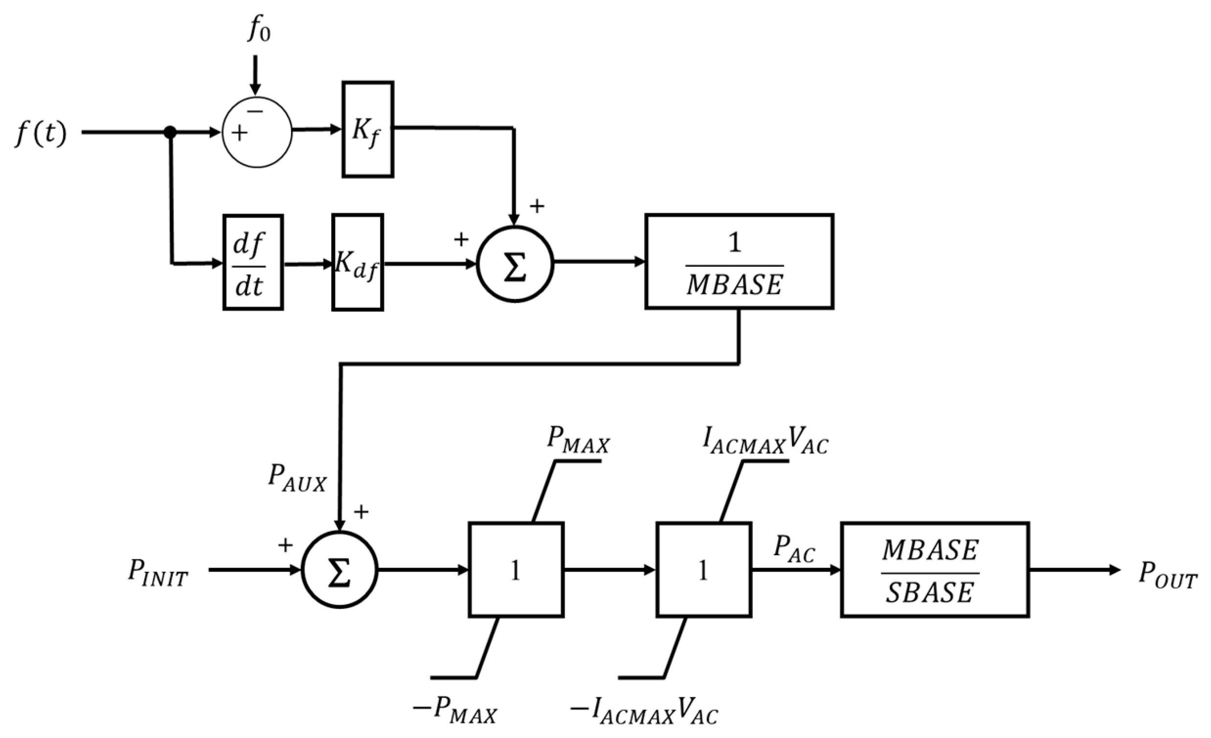
3.1. Active Power Control Loop
Figure 3 represents the active power control loop. The active power order determined by the adaptive droop controller is added to the initial power output of ESS, then, pass through the limiter block of power and current ratings.
The model developed in this paper is the TSA dynamic model. Thus the inner controller is simplified as the converter equation. Therefore, the active power output is controlled by the order determined in Figure 3.
Auxiliary power order is provided by the proposed control method when the control is activated.
3.2. Reactive Power Control Loop
The reactive power controller is shown in Figure 4, and the reactive power order is determined by the controller. Voltage error between the connected bus voltage and the reference voltage determines the reactive current, after that, the signal passes through the lead-lag compensator to secure the output stability and the integrator to secure the control speed and multiplies the grid voltage to determine the reactive power output. Also, voltage control droop is applied in the control loop, and the model parameter can modify the percentage for the droop.
3.3. Charge/Discharge Efficiency
The charge and discharge state is determined by active power output. The ESS is operated as discharge mode when the active power output is larger than zero and charge mode when the output is lower than zero. The block diagram to consider the power conversion efficiency is configured as shown in Figure 5.
3.4. ESS Operation Algorithm
The FR-ESS control schemes based on the proposed methodologies described in Section 2 and Section 3 in detail. As shown in Figure 6, to utilize the adaptive droop control method, the information of the power system condition of frequency deviation () has to be collected by ESS main controller. Based on information such as with active power deviation, the system characteristics of effective inertia () can be assessed as described in Section 2. In the result, the main controller can calculate the droop coefficient for primary frequency response () and inertial response () appropriately. In the frequency recovery stage, a synthetic droop method is applied to prevent the frequency recovery delay caused by the inertial response, which leads to SoC management when entering the frequency dead band.
4. Case Study
The demonstration project of the FR-ESS is in progress in real power systems in many countries [18]. In Korea, the ESS for FR applications is currently installed at about 376 MW capacity, as shown in Figure 7, and demonstrating its effectiveness in several contingency situations and capacity expansion is under review [25]. In this study, we assumed that the total capacity as 1 GW to study the effect of large scale ESS on the power system. The ESS capacity shown in the Figure 6 was approximately tripled.
The short circuit ratio (SCR), the ratio of short-circuit capacity of the system versus the capacity of the ESS, can be an important factor for the stable operation of the power system [19]. Therefore, a case study was conducted for heavy load cases with 90% load and 70% light load case compared to the peak. Normally, when the load demand is high, the number of in-service generator increases. Accordingly, the system has a high short circuit capacity and the system strength. The droop coefficient has to be modified to an appropriate value. The parameters are summarized in Table 1.
4.1. Heavy Load Condition
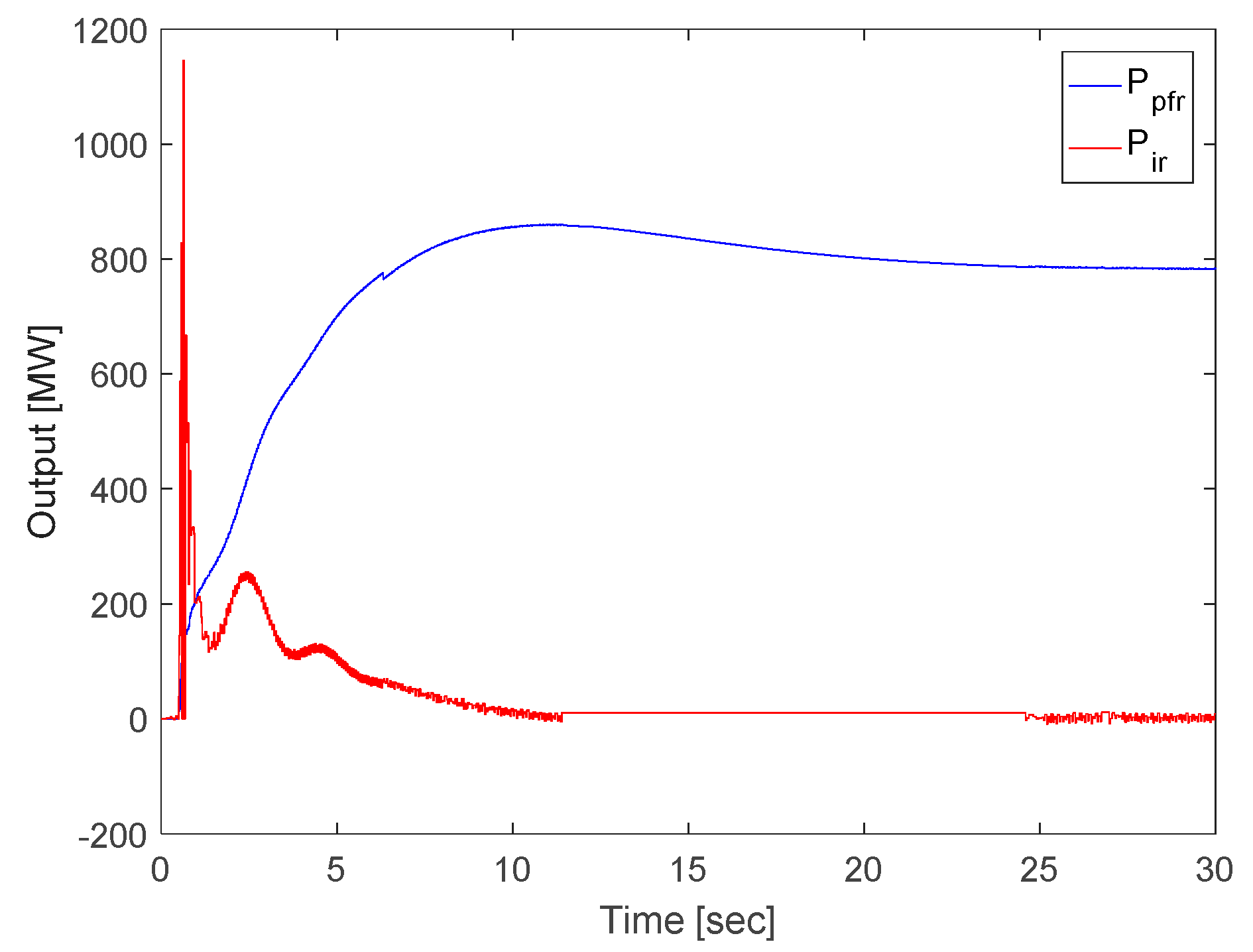
In the Korean power system, the largest capacity of the generator is 1460 MW NP, and we select the case with 1460 MW NP trip case. As shown in Figure 8, the thermal generators increase their active power to compensate for the frequency drop according to the generator outage as governor free action. The total amount is 1500 MW in this governor free capacity in the Korean power system. Figure 8 shows that the comparison between governor free with the thermal generator, ESS compensation with the fixed droop and with proposed adaptive droop control. In the steady-state point of view, three cases converged to a stable frequency operation point. However, there are significant differences in transient state. ESS is much faster than governor free, so RoCoF is smaller, and frequency nadir is also higher. The maximum limit is set to 0.2 with the proposed method. As shown in Figure 9 and Figure 10, the output is added to of conventional fixed frequency droop control. This supply the power additionally when the and the system frequency . In the result, the proposed method can lower the frequency descent rate and increase the frequency nadir.
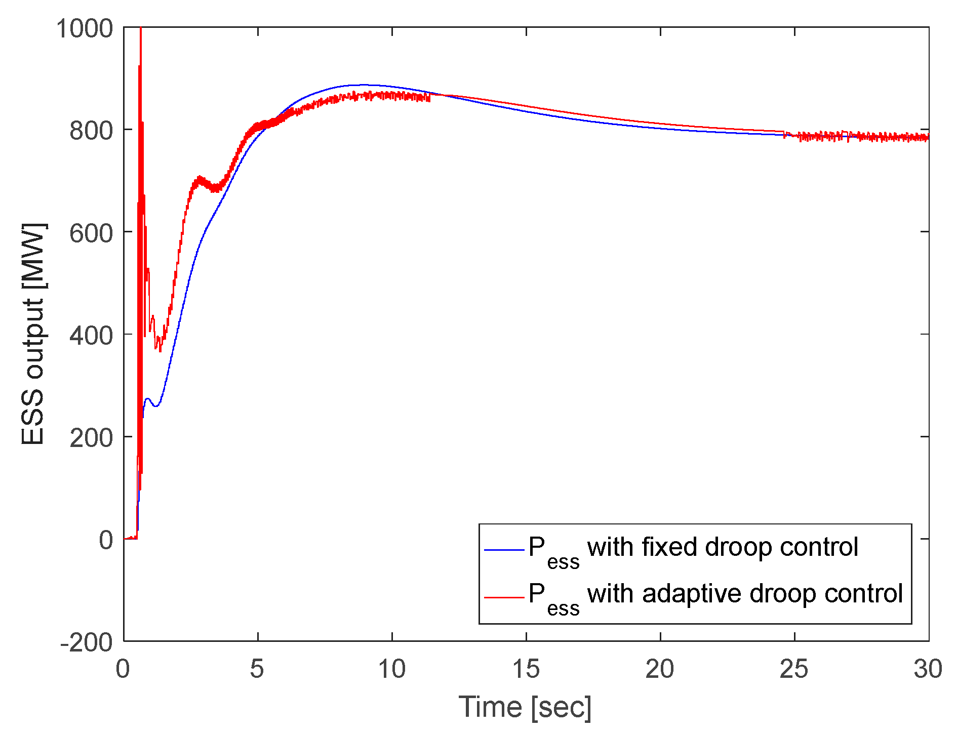
4.2. Light Load Condition
With small SCR, the power charge/discharge operation of the ESS can have a significant impact on the grid frequency. As shown in Figure 11, the frequency drop with 1460 MW NP outage is deeper compared to the heavy load case. In this case, the maximum limit is supposed to be 0.2 also. In the result, the frequency response of ESS with proposed adaptive droop shows effectiveness to relief the frequency nadir and RoCoF. The outputs compared to the droop mode of the ESS are shown in Figure 12 and Figure 13.
5. Conclusions
In this paper, a method to improve the transient response of ESS by using the RoCoF term by estimating the proper droop coefficient according to the power system condition is proposed. To verify the proposed method, a power balance equation and a controller were modeled, and a dynamic simulation was performed. The results from case studies show that frequency regulation using ESS can be effective in contingencies such as a sudden trip of large-capacity generators rather than frequency regulation using governor free of conventional thermal power generators. Especially when the proposed method is applied, it contributes to lowering the frequency decline rate, RoCoF, and increasing the lowest frequency nadir, thereby improving the frequency stability. The case study confirmed that it could be adaptive in different power system conditions both 70% and 90% load situations. The control method and logic can be used not only to improve the response characteristics of the ESS installed for frequency regulation purposes, but also to be used for configuring the controller when participating in the frequency response of the ESS for demand response based on Time-of-Use or ESS for renewable energy compensation.
Based on the study, it is expected that proposed method can be utilized to study emergency control in communication failure situation based on assessment the exact effective inertia of the system and coordinated control with renewable energy converter for primary frequency response and automatic generation control (AGC) considering state-of-charge (SoC) of the ESS.
Author Contributions
Conceptualization, S.H., G.J., S.J., and M.Y.; Investigation, S.S.; Methodology, Y.Y., S.J., and M.Y.; Supervision, M.Y.; Validation, Y.Y.; Visualization, J.L. and S.S.; Writing—original draft, S.H., J.L., and M.Y.; Writing—review and editing, S.J.
Funding
This work was supported by the Korea Institute of Energy Technology Evaluation and Planning (KETEP) and the Ministry of Trade, Industry & Energy (MOTIE) of the Republic of Korea (No. 20182410105330) and National Research Foundation Grant (No. 2017R1C1B5018073) funded by the Korean government.
Conflicts of Interest
The authors declare no conflict of interest.
Nomenclature
| inertia constant of the system | |
| total capacity of the generators in the system | |
| frequency before the variation is occurred | |
| system frequency | |
| inertia constant of the individual generator | |
| capacity of the generator | |
| K | system constant |
| output order in transient mode | |
| rated capacity of the target machine | |
| target speed rate of output change | |
| normal frequency | |
| steady state droop constant for the ESS | |
| capacity of the ESS | |
| gain for frequency variation | |
| gain for RoCoF |
References
- Frankfurt School-UNEP Collaborating Centre. Global Trends in Renewable Energy Investment; BloombergNEF: New York, NY, USA, 2018. [Google Scholar]
- Chompoo-Inwai, C.; Lee, W.J.; Fuangfoo, P.; Williams, M.; Liao, J.R. System Impact Study for the Interconnection of Wind Generation and Utility System. IEEE Trans. Ind. Appl. 2005, 41, 163–168. [Google Scholar] [CrossRef]
- Kroposki, B.; Johnson, B.; Zhang, Y.; Gevorgian, V.; Denholm, P.; Hodge, B.-M.; Hannegan, B. Achieving a 100% Renewable Grid: Operating Electric Power Systems with Extremely High Levels of Variable Renewable Energy. IEEE Power Energy Mag. 2017, 15, 61–73. [Google Scholar] [CrossRef]
- Sharma, S.; Huang, S.-H.; Sarma, N. System Inertial Frequency Response estimation and impact of renewable resources in ERCOT interconnection. In Proceedings of the IEEE PES General Meeting, Detroit, MI, USA, 24–28 July 2011; Institute of Electrical and Electronics Engineers (IEEE): Piscataway, NJ, USA, 2011; pp. 1–6. [Google Scholar]
- Feltes, J.W.; Gemmell, B.D.; Retzmann, D. From Smart Grid to Super Grid: Solutions with HVDC and FACTS for grid access of renewable energy sources. In Proceedings of the 2011 IEEE Power and Energy Society General Meeting, Detroit, MI, USA, 24–28 July 2011; Institute of Electrical and Electronics Engineers (IEEE): Piscataway, NJ, USA, 2011; pp. 1–6. [Google Scholar]
- Suberu, M.Y.; Mustafa, M.W.; Bashir, N. Energy storage systems for renewable energy power sector integration and mitigation of intermittency. Renew. Sustain. Energy Rev. 2014, 35, 499–514. [Google Scholar] [CrossRef]
- Akhil, A.A.; Huff, G.; Currier, A.B.; Kaun, B.C.; Rastler, D.M.; Chen, S.B.; Cotter, A.L.; Bradshaw, D.T.; Gauntlett, W.D. DOE/EPRI Electricity Storage Handbook in Collaboration with NRECA; Sandia National Laboratories: Albuquerque, NM, USA, 2015.
- Günter, N.; Marinopoulos, A. Energy storage for grid services and applications: Classification, market review, metrics, and methodology for evaluation of deployment cases. J. Energy Storage 2016, 8, 226–234. [Google Scholar] [CrossRef]
- Kundur, P.; Balu, N.J.; Lauby, M.G. Power System Stability and Control; McGraw-hill: New York, NY, USA, 1994. [Google Scholar]
- Rebours, Y.G.; Kirschen, D.S.; Trotignon, M.; Rossignol, S. A Survey of Frequency and Voltage Control Ancillary Services—Part I: Technical Features. IEEE Trans. Power Syst. 2007, 22, 350–357. [Google Scholar] [CrossRef]
- Li, P.; Wang, X.; Lee, W.-J.; Xu, D. Dynamic Power Conditioning Method of Microgrid Via Adaptive Inverse Control. IEEE Trans. Power Deliv. 2015, 30, 906–913. [Google Scholar] [CrossRef]
- Hwang, M.; Muljadi, E.; Park, J.-W.; Sørensen, P.E.; Kang, Y.C. Dynamic Droop–Based Inertial Control of a Doubly-Fed Induction Generator. IEEE Trans. Sustain. Energy 2016, 7, 924–933. [Google Scholar] [CrossRef]
- Wang, W.; Li, Y.; Cao, Y.; Hager, U.; Rehtanz, C.; Haeger, U. Adaptive Droop Control of VSC-MTDC System for Frequency Support and Power Sharing. IEEE Trans. Power Syst. 2017, 33, 1264–1274. [Google Scholar] [CrossRef]
- Swierczynski, M.J.; Stroe, D.I.; Stan, A.I.; Teodorescu, R.; Stroe, D.L. Primary frequency regulation with Li-ion battery energy storage system: A case study for Denmark. In Proceedings of the 2013 IEEE ECCE Asia Downunder, Melbourne, Australia, 3–6 June 2013; Institute of Electrical and Electronics Engineers (IEEE): Piscataway, NJ, USA, 2013; pp. 487–492. [Google Scholar]
- Xu, B.; Dvorkin, Y.; Kirschen, D.S.; Silva-Monroy, C.A.; Watson, J.-P. A comparison of policies on the participation of storage in U.S. frequency regulation markets. In Proceedings of the 2016 IEEE Power and Energy Society General Meeting (PESGM), Boston, MA, USA, 17–21 July 2016; Institute of Electrical and Electronics Engineers (IEEE): Piscataway, NJ, USA, 2016; pp. 1–5. [Google Scholar] [Green Version]
- Sanchez, F.; Cayenne, J.; Gonzalez-Longatt, F.; Rueda, J.L. Controller to enable the enhanced frequency response services from a multi-electrical energy storage system. IET Gener. Transm. Distrib. 2018, 13, 258–265. [Google Scholar] [CrossRef]
- Stroe, D.-I.; Knap, V.; Swierczynski, M.; Stroe, A.I.; Teodorescu, R. Suggested operation of grid-connected lithium-ion battery energy storage system for primary frequency regulation: Lifetime perspective. In Proceedings of the 2015 IEEE Energy Conversion Congress and Exposition (ECCE), Montreal, QC, Canada, 20–24 September 2015; Institute of Electrical and Electronics Engineers (IEEE): Piscataway, NJ, USA, 2015; pp. 1105–1111. [Google Scholar] [Green Version]
- Luo, X.; Wang, J.; Dooner, M.; Clarke, J. Overview of current development in electrical energy storage technologies and the application potential in power system operation. Appl. Energy 2015, 137, 511–536. [Google Scholar] [CrossRef] [Green Version]
- Gundogdu, B.M.; Nejad, S.; Gladwin, D.T.; Foster, M.P.; Stone, D.A. A Battery Energy Management Strategy for U.K. Enhanced Frequency Response and Triad Avoidance. IEEE Trans. Ind. Electron. 2018, 65, 9509–9517. [Google Scholar] [CrossRef]
- Canevese, S.; Cirio, D.; Gatti, A.; Rapizza, M.; Micolano, E.; Pellegrino, L. Simulation of enhanced frequency response by battery storage systems: The UK versus the continental europe system. In Proceedings of the 2017 IEEE International Conference on Environment and Electrical Engineering and 2017 IEEE Industrial and Commercial Power Systems Europe (EEEIC/I&CPS Europe), Milan, Italy, 6–9 June 2017; Institute of Electrical and Electronics Engineers (IEEE): Piscataway, NJ, USA, 2017; pp. 1–6. [Google Scholar]
- Lopes, L.A. Self-Tuning Virtual Synchronous Machine: A Control Strategy for Energy Storage Systems to Support Dynamic Frequency Control. IEEE Trans. Energy Convers. 2014, 29, 833–840. [Google Scholar]
- Knap, V.; Chaudhary, S.K.; Stroe, D.-I.; Swierczynski, M.J.; Craciun, B.-I.; Teodorescu, R.; Stroe, D.L. Sizing of an Energy Storage System for Grid Inertial Response and Primary Frequency Reserve. IEEE Trans. Power Syst. 2015, 31, 3447–3456. [Google Scholar] [CrossRef] [Green Version]
- Liu, J.; Wen, J.; Long, Y.; Yao, W. Solution to short-term frequency response of wind farms by using energy storage systems. IET Renew. Power Gener. 2016, 10, 669–678. [Google Scholar] [CrossRef]
- Han, J.B.; Kook, K.S.; Chang, B. A Study on the Criteria for Setting the Dynamic Control Mode of Battery Energy Storage System in Power Systems. Trans. Korean Inst. Electr. Eng. 2013, 62, 444–450. [Google Scholar] [CrossRef] [Green Version]
- Hur, W.; Moon, Y.; Shin, K.; Kim, W.; Nam, S.; Park, K. Economic Value of Li-ion Energy Storage System in Frequency Regulation Application from Utility Firm’s Perspective in Korea. Energies 2015, 8, 5000–5017. [Google Scholar] [CrossRef]
Figure 1.
Frequency response characteristic.

Figure 2.
The structure of the ESS system.
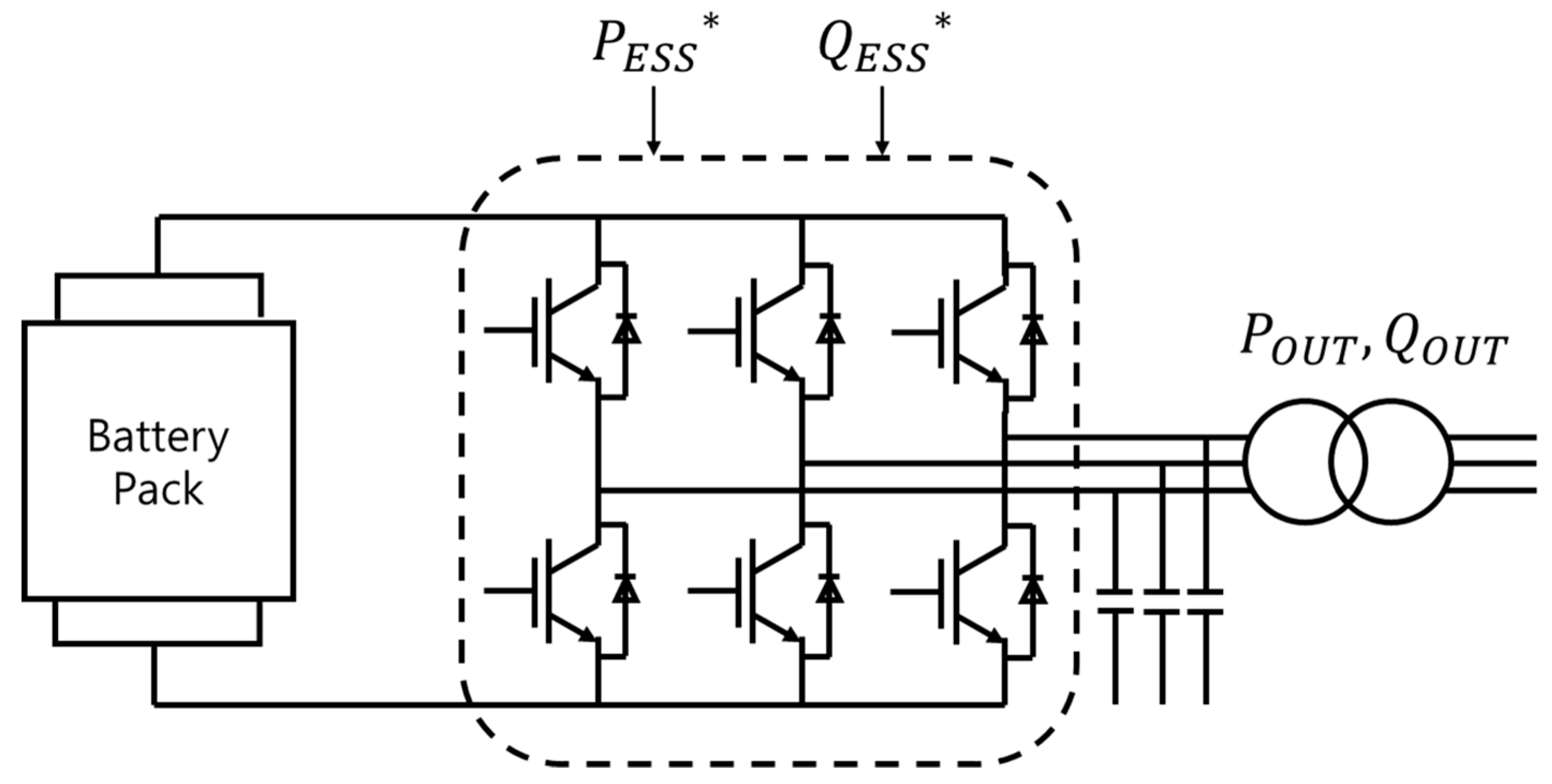
Figure 3.
The active power control loop.

Figure 4.
The reactive power control loop.

Figure 5.
The charge and discharge mode.

Figure 6.
The control algorithm of the proposed method.

Figure 7.
The current frequency regulation (FR)-ESS installation in Korea.
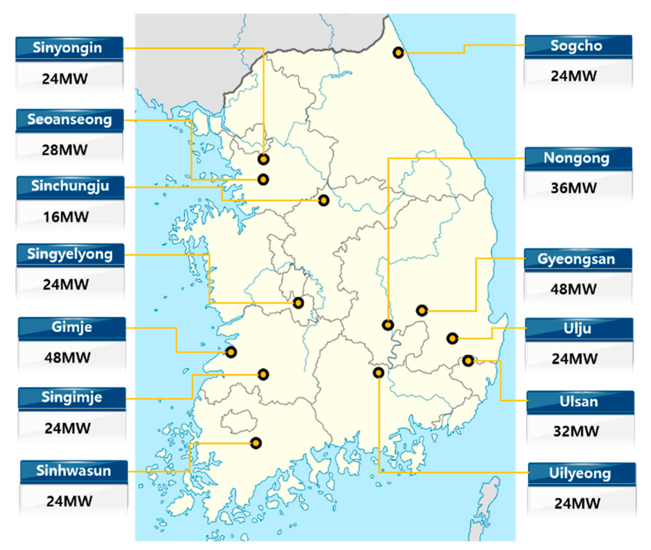
Figure 8.
Comparison of system frequency with generator trip.
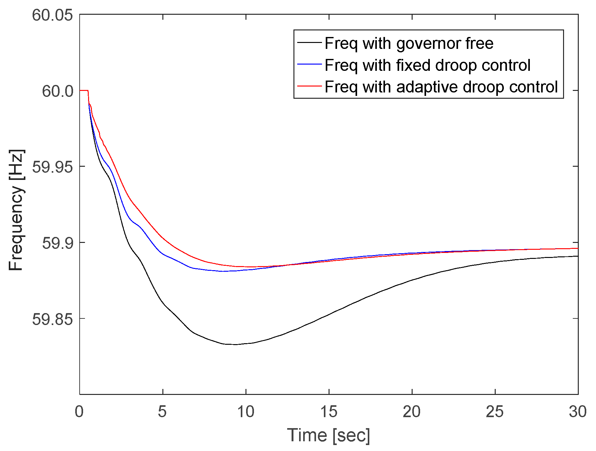
Figure 9.
ESS power output element with adaptive droop.
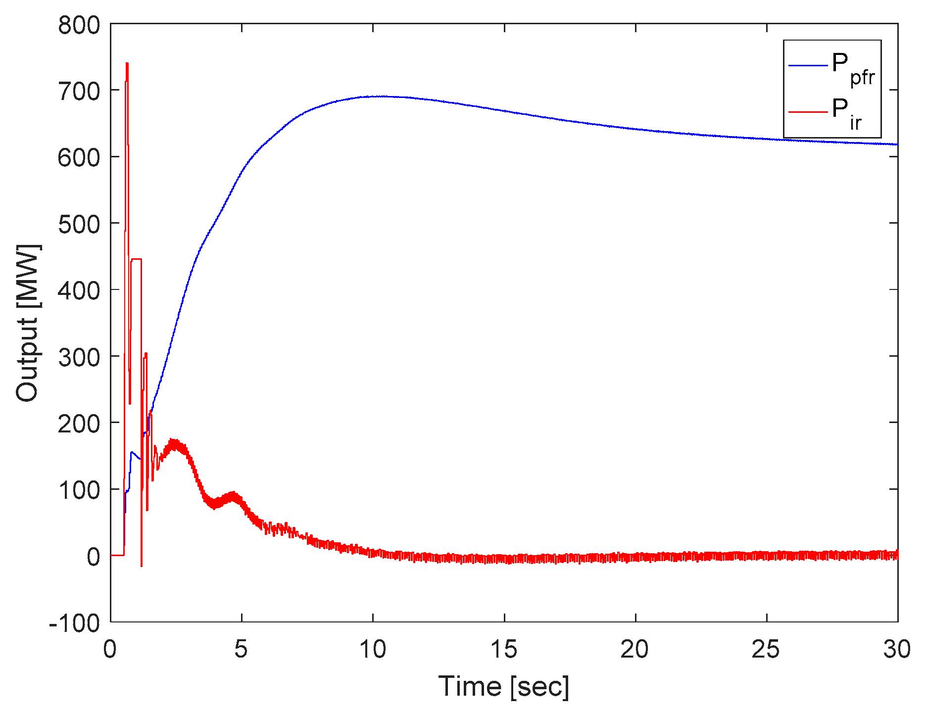
Figure 10.
ESS power output depending on droop control.
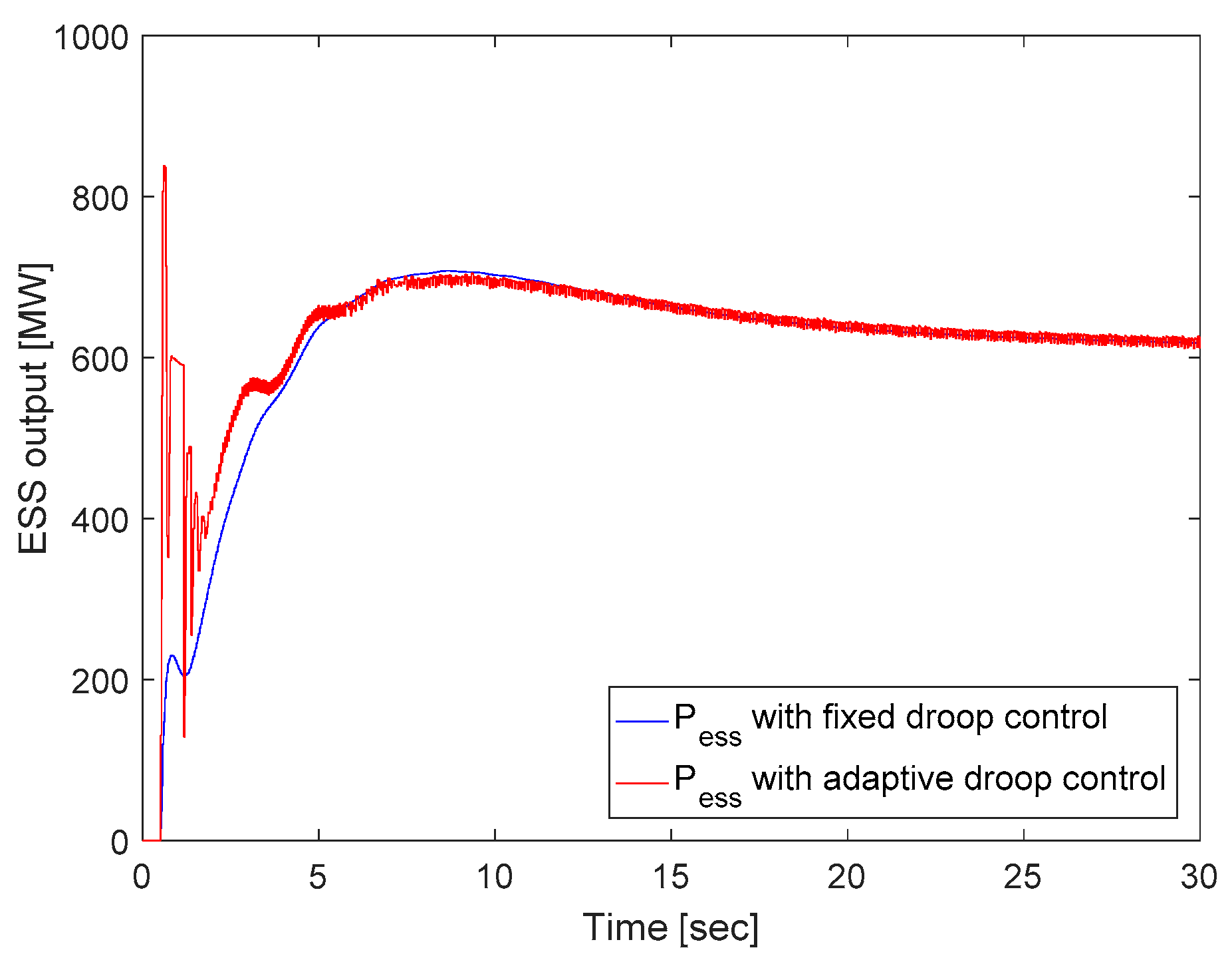
Figure 11.
Comparison of system frequency with generator trip.
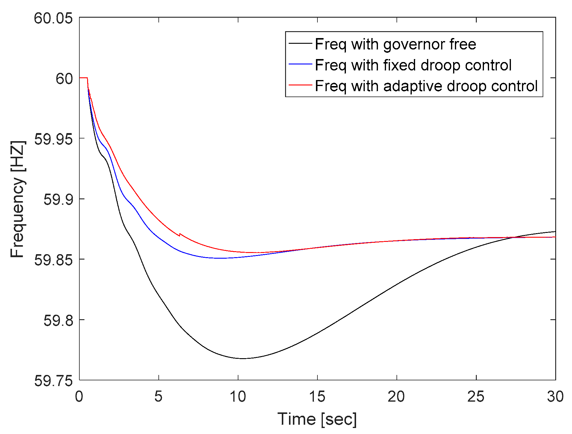
Figure 12.
ESS power output element with adaptive droop.

Figure 13.
ESS power output depending on droop control.

Table 1.
Comparison of load condition.
| Criteria | 90% Load | 70% Load |
|---|---|---|
| load | 85 GW | 52 GW |
| 0.54 | 0.62 | |
| 81,111 MVA | 70,645 MVA | |
| 5.95 | 5.95 | |
| 4.60 | 4.95 |
© 2019 by the authors. Licensee MDPI, Basel, Switzerland. This article is an open access article distributed under the terms and conditions of the Creative Commons Attribution (CC BY) license (http://creativecommons.org/licenses/by/4.0/).
Share and Cite
MDPI and ACS Style
Yoon, M.; Lee, J.; Song, S.; Yoo, Y.; Jang, G.; Jung, S.; Hwang, S. Utilization of Energy Storage System for Frequency Regulation in Large-Scale Transmission System. Energies 2019, 12, 3898. https://doi.org/10.3390/en12203898
AMA Style
Yoon M, Lee J, Song S, Yoo Y, Jang G, Jung S, Hwang S. Utilization of Energy Storage System for Frequency Regulation in Large-Scale Transmission System. Energies. 2019; 12(20):3898. https://doi.org/10.3390/en12203898
Chicago/Turabian StyleYoon, Minhan, Jaehyeong Lee, Sungyoon Song, Yeontae Yoo, Gilsoo Jang, Seungmin Jung, and Sungchul Hwang. 2019. "Utilization of Energy Storage System for Frequency Regulation in Large-Scale Transmission System" Energies 12, no. 20: 3898. https://doi.org/10.3390/en12203898
Note that from the first issue of 2016, this journal uses article numbers instead of page numbers. See further details here.