Review

Challenges of Fast Charging for Electric Vehicles and the Role of Red Phosphorous as Anode Material: Review

1
School of Materials Science and Energy Engineering, Foshan University, Foshan 528225, China
2
Institute of Nuclear and New Energy, Tsinghua University, Beijing 100084, China
3
Chemical Sciences and Engineering Division, Argonne National Laboratory, Argonne, IL 60439, USA
*
Author to whom correspondence should be addressed.
Energies 2019, 12(20), 3897; https://doi.org/10.3390/en12203897
Submission received: 11 September 2019 / Revised: 29 September 2019 / Accepted: 8 October 2019 / Published: 15 October 2019
(This article belongs to the Special Issue Electric Vehicle Charging: Social and Technical Issues)

Abstract

:
Electric vehicles (EVs) are being endorsed as the uppermost successor to fuel-powered cars, with timetables for banning the sale of petrol-fueled vehicles announced in many countries. However, the range and charging times of EVs are still considerable concerns. Fast charging could be a solution to consumers’ range anxiety and the acceptance of EVs. Nevertheless, it is a complicated and systematized challenge to realize the fast charging of EVs because it includes the coordinated development of battery cells, including electrode materials, EV battery power systems, charging piles, electric grids, etc. This paper aims to serve as an analysis for the development of fast-charging technology, with a discussion of the current situation, constraints and development direction of EV fast-charging technologies from the macroscale and microscale perspectives of fast-charging challenges. If the problem of fast-charging can be solved, it will satisfy consumers’ demand for 10-min charging and accelerate the development of electric vehicles. This paper summarized the development statuses, issues, and trends of the macro battery technology and micro battery technology. It is emphasized that to essentially solve the problem of fast charging, the development of new battery materials, especially anode materials with improved lithium ion diffusion coefficients, is the key. Finally, it is highlighted that red phosphorus is one of the most promising anodes that can simultaneously satisfy the double standards of high-energy density and fast-charging performance to a maximum degree.

Graphical Abstract

1. Introduction

Electric vehicles (EVs) are receiving increasing attention because they offer the potential benefits of reducing dependence on fossil fuels and improving urban air quality, thus helping the transition to more sustainable and eco-friendly travel [1,2]. With the continuous progress of batteries, motors, and electrical control technologies; and the increasing development of informationization, network connection, and intellectualization for pure EVs, the cost performance of EVs will reach or exceed that of conventional fuel vehicles by 2025 at the latest. However, for petrol vehicles, filling with fuel only requires 2 to 5 min, whereas for common EVs on the market, general charging requires 6–8 h to achieve fully charged batteries. Such a long charging time is barely acceptable for ordinary consumers with EVs as commuting tools, but it is totally unacceptable when using EVs as operating vehicles, such as taxis and logistics vehicles. Usually, a ’10-min full charge’ is the ideal appeal for users. Fast-charging can be achieved in two typical ways, namely a high voltage or high current mode. However, if the charging voltage is increased greatly, the insulation level of the vehicle must be upgraded, and the requirements on the quality of electronic components for the vehicle should be high, resulting in extra cost. If the current is increased greatly, it will inevitably lead to a heating problem. Whether high voltage or high current, vehicle battery technology not only need to meet the electrochemical and thermal demands of fast-charging but also the battery pack, charging pile, and power grid must be capable of handling the high charging power [3]. Thus, fast-charging is a complicated and systematized technology.
Fast-charging has attracted people’s attention and a series of review articles about enabling fast charging have been reported. They focused on vehicle [4], battery technology gap [5], thermal management [6], and infrastructure/economic considerations [7], respectively. Also, there is some academic review focused on rational material design [8], which presents the state-of-the-art developments in ultrafast charging LIBs by the rational design of materials. It is especially worth mentioning that a recent review study from Professor Cuiyi discussed the challenges and future research directions towards fast charging at the level of battery materials, charge transfer, and characterization techniques for battery designs [9]. Based on current literature, herein, we not only discuss the issue, but also the solution to EV fast-charging. We reorganize the utility-scale battery storage system into three parts: a battery system, a charging pile system, and a power grid, as shown in Figure 1 [10]. For the convenience of the following review, we classified the battery system of the vehicle, charging pile, and power grid as macro battery technology and the battery cell, including the cell materials, as micro battery technology. The development statuses, issues, and trends of the macro battery technology and micro battery technology will be summarized as follows. In particular, the view expressed in this paper is that lithium-ion batteries can be quickly charged to a certain extent through macroscopic charging technology, but it is currently hard to achieve real fast charging, which depends on a breakthrough of battery materials. Moreover, it is highlighted that red phosphorus is a promising anode that can simultaneously satisfy the double standards of high-energy density and fast-charging performance to a maximum degree.

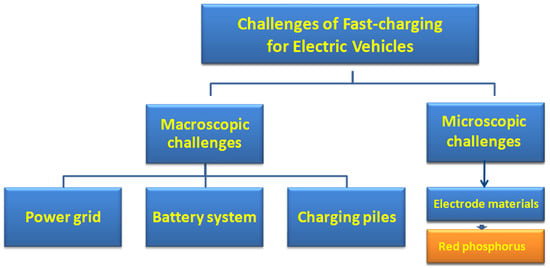
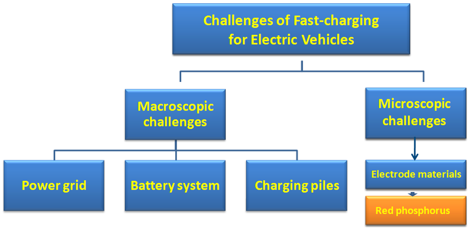
2. Macroscopic Challenges in EV Fast Charging

2.1. Consideration in the Battery Systems of EVs

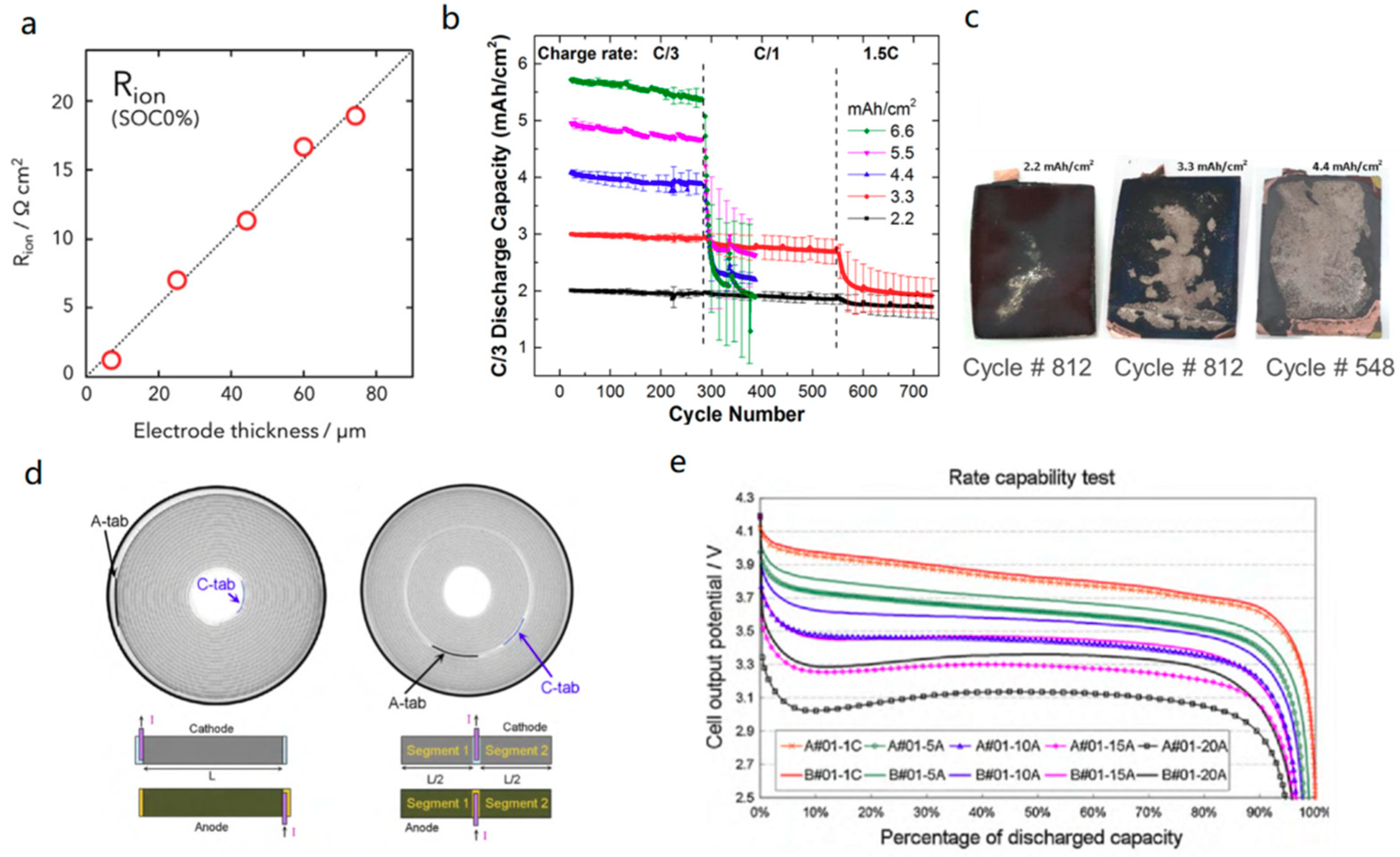
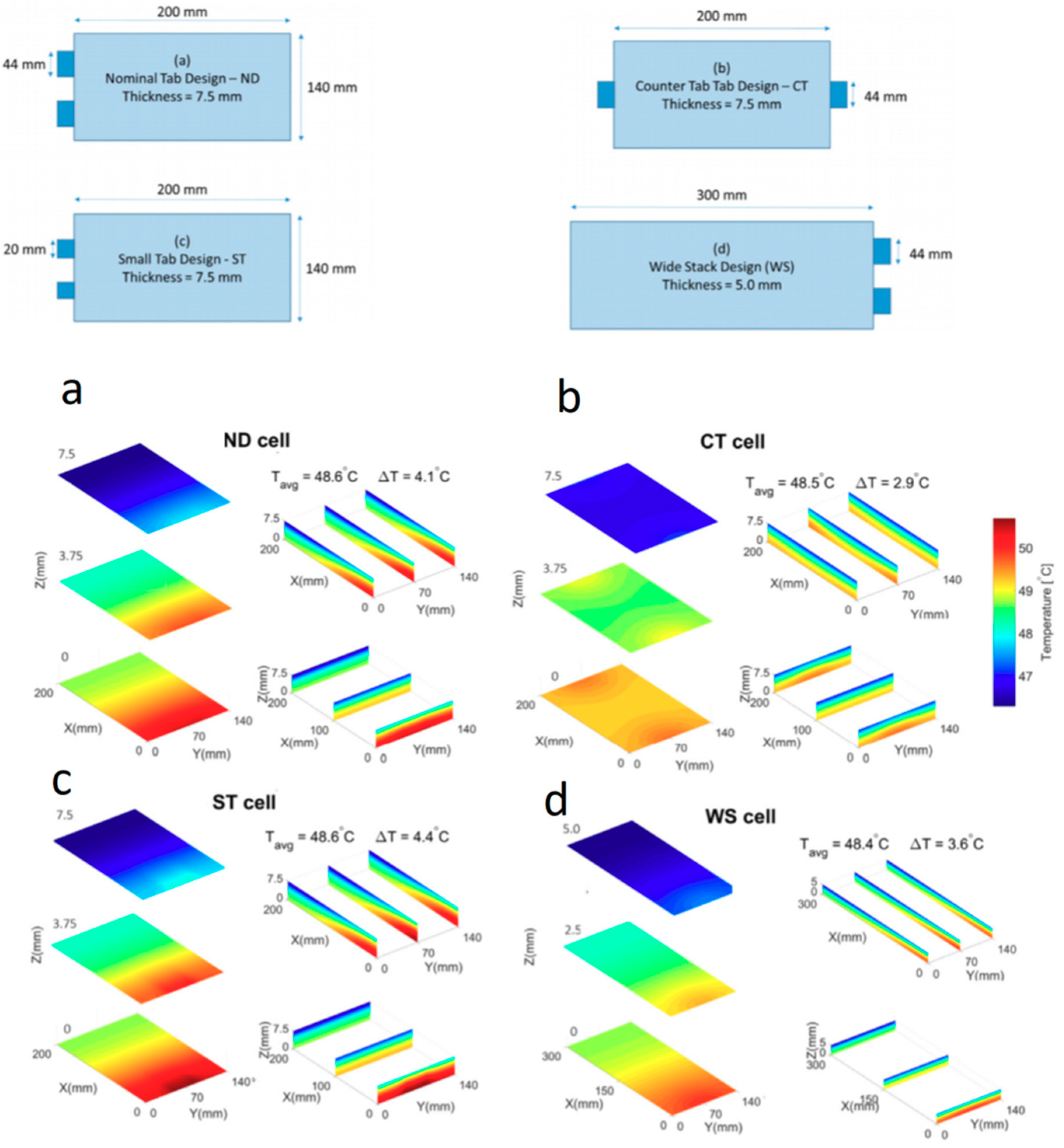
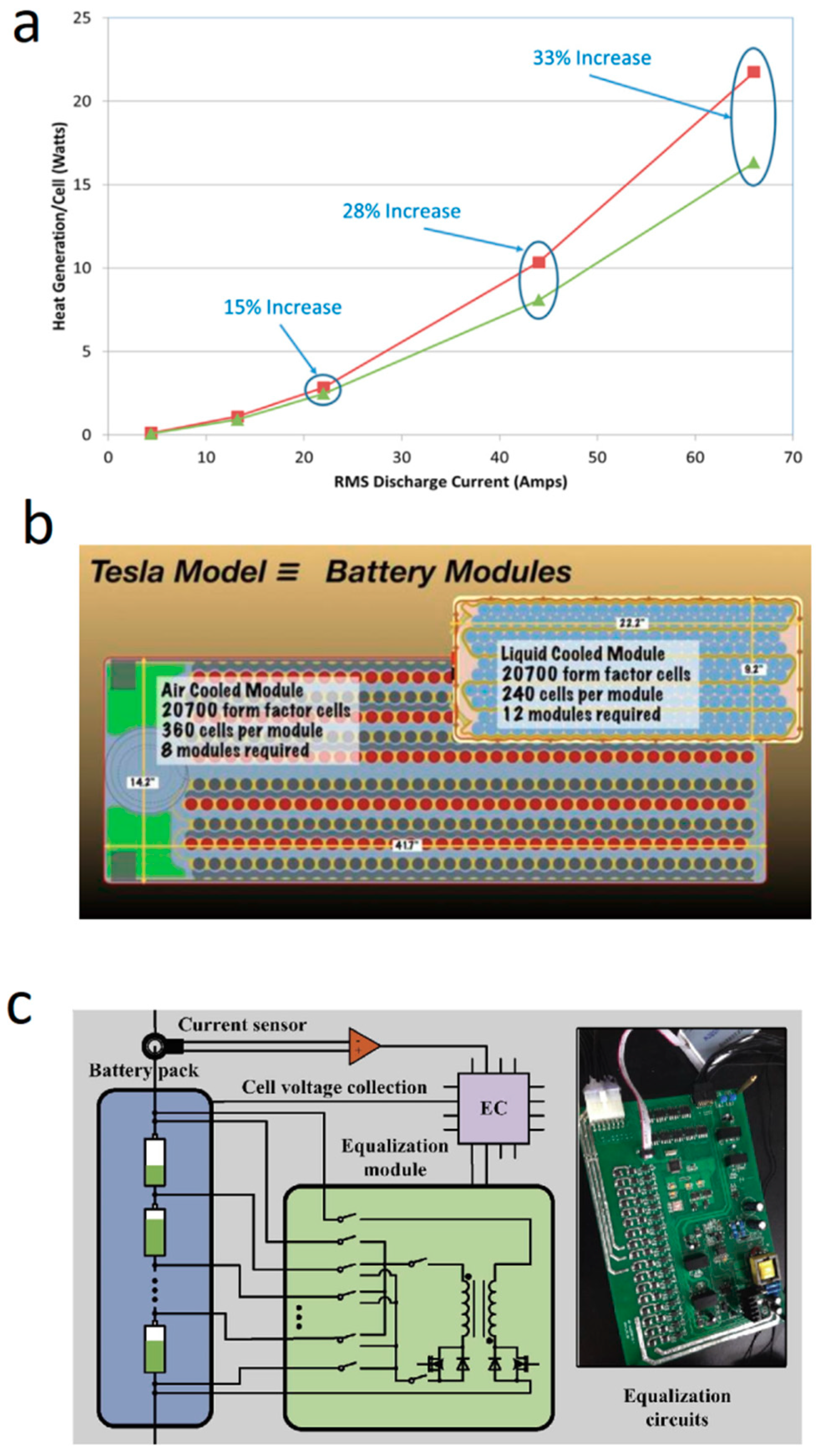
2.1.1. Battery/Battery Pack Design

To support the fast-charging performance of the cell, considerable effort goes into the design of a single cell battery pack. Generally, the fast-charging performance of a single cell can be improved by adding more conductive agent to the electrode [11], reducing the loading of the electrode material (thinner coating), using a thicker collector, adjusting the suitable tab position, retaining a larger electrode porosity [12,13], ensuring less electrode bending [14], etc. These methods can improve the kinetic and electrical properties and reduce the internal resistance of cells. A study analyzed the internal resistance of electrodes with various thicknesses ranging from 10 μm to 150 μm and revealed that the Rion was proportional to the thickness of the electrode as shown in Figure 2a [15]. Furthermore, it was proved that electrodes with loadings higher than ~3 mAh/cm2 were unable to sustain a charge rate higher than C/1 as shown in Figure 2b. In addition, it was found that an increased graphite loading gave an increased Li deposition after long cycling as shown in Figure 2c; this result was obtained with capacity-matched cells using graphite as negative electrodes and LiNi0.6Mn0.2Co0.2O2 (NMC) as positive electrodes. Moreover, the performances of both center-tab and traditional designs were compared when other components in the cell were fixed [16]. The results showed that when the cells are discharged at a high C-rate, the cells with center tab (B#01) have an obviously higher voltage platform than those of the cells with traditional designs (A#01) at different discharging currents, especially at high C-rates of 15 C and 20 C as shown in Figure 2e. It was proposed that the significantly different results came from reducing the resistance of the electrode because this electrode can be thought of as two segments in parallel with the length of L/2, as shown in Figure 2d. It was also declared that adding additional tabs was not recommended since multi tabs increased the design complexity and resulted in poor reliability [16]. For the sake of safety, battery design was also studied in terms of the effect on the temperature distribution of the tab position/width and the size of the cells [17,18]. As shown in Figure 3, with the same tab width for both designs (44 mm), the nominal tab design (ND cell) had a temperature difference of 4.1 °C across the cell, whereas the counter tab design (CT cell) had a temperature difference of 2.9 °C across the cell. This meant the tab position obviously affected the temperature distribution. For the same tab position and different tab widths of 44 mm (normal tab design-ND) and 20 mm (counter tab design-CT), the values of the temperature differences were 4.1 °C and 4.4 °C, respectively, which was different than before [6]. The temperature differences can be explained by the electrical current in the current collector foils converging to or diverging from the tabs of the cells. Typically, rapid electrostatic potential changes occur in the composite materials near the tabs, leading to a large local deviation from thermodynamic equilibrium. Meanwhile, the wide stacks design (WS) cell is 1.5-times that of ND cell, which means that the WS cell has a smaller electrical resistance, resulting in a smaller temperature difference of 3.6 °C than that of 4.1 °C for the ND cell.
However, the battery pack not only contains single cells but also electronic connection components, battery management systems, etc. Even though the fast-charging performance of a single cell is good and the power density is high, the assembled battery pack does not always have a high power density [20]. In most cases, the designs for fast-charge performance significantly increase the overall cost of the entire battery system. For example, for the pack with 85 kWh energy and 240 cells (pack detail is shown in the caption of Table 1), when the electrode thickness decreases from 103 cm to 14 um, the charging time is greatly reduced from 61 min to 8 min, but the cost increases by 126 USD/kWh. Additionally, the charger power increased by 524 kW, and the heat generated increased by over 60%, concomitantly, as summarized in Table 1 [5]. Thus, cost is definitely an obstacle for fast-charging for EVs. Meanwhile, the higher heat generated and higher charger power should also be considered.

2.1.2. BMS Design

The battery management system (BMS) should be especially considered in fast-charging battery systems because it seems that increasing temperature is the main reason for the accelerated aging of the cell in high-power applications [21]. The total irreversible heating is generated in the electrodes, separators, and current collectors as a result of electrochemical reaction and potential drop [22]. The generated heating inside the cell is not completely uniform because the electronic resistance, ionic resistance, and electrochemical reaction static resistance inside the cell are also unevenly distributed, which is accelerated in a fast-charging state. Further study showed that the heat generation normalized of each cell in the pack is approximately 30% greater than that for a single cell, as shown in Figure 4a [14]. The resistance between conductors and plug-ins is also relatively high in fast-charging battery systems. Thus, even though the design is optimized for high power/current, the interconnections will provide a substantial amount of heat above and beyond the cells [23]. To solve the problem of heat dissipation, BMS typically air, liquid, or refrigerant cooling are used to control the temperature of the cells [24,25,26]. Figure 4b provides some information about air-cooling and liquid-cooling BMS structures as a reference. The drawing illustrates the difference between an air-cooled and a liquid-cooled battery module in the Tesla Model. Compared with the liquid-cooled battery module, the air-cooled module is largely filled with air passages but is much simpler than the liquid cooled modules, since the cooling air can directly contact the cells without separate, electrically isolated cooling ducts or plates. The air-cooling technique circulates ambient or actively cooled air through the battery pack, and the heat is expelled to the surroundings, which requires large surface areas to extract the heat [27]. Liquid cooling is the preferred thermal management strategy for most EV systems on the market today since the liquid cooling systems have higher heat capacity and thermal conductivity compared to air systems [28]. Liquid cooling also reduces the diameter of the cable, making it easier for users to use and is an international solution [29]. Liquid media typically involve a combination of ethylene glycol (EG) and water due to their low cost. In fact, there is a large amount of room for the optimization of liquid media, and studies show that carbon nanotubes or alumina can increase the thermal conductivity of EG-water as a nanofluid [30,31].
However, the liquid flow channels are typically complex and require an extensive number of connections, leading to an increasing potential for failure [33]. Thus, when we design a TMS for a fast-charging battery system, we should balance, from all angles, the charging C-rate, the ohmic heat and the cost of cooling the system [34]. It is necessary to note that an equalization module in a BMS, as shown in Figure 4c, is required for fast charging to ensure that all cells are equally charged or discharged. The equalizing module is essential (i) to improve the consistency between single cells, (ii) to protect the cell from the state of long-term overcharge and over discharge, and (iii) to reduce the maintenance cost of battery packs due to monomer consistency, or even the cost of a battery pack replacement [32]. A direct cell-to-cell battery equalizer including a quasi-resonant LC converter and a boost DC-DC converter was developed in which the quasi-resonant LC converter could induce power losses; meanwhile, the boost DC-DC converter can enhance the equalization voltage difference for a big balancing current and zero-voltage difference between the batteries [35]. An intelligent control model is proposed to activate the bidirectional switches and control direct current (DC-DC) converter switches with pulse width modulation of generation unit. This model was proven suitable for lithium-ion batteries in EVs [36].
To achieve fast-changing performance with less battery life degradation, systems with different combinations of battery packs and BMSs were studied [14]. As illustrated in Table 2, Case 4, if charged at 350 kW, the value of heat generation per cell (W) was the lowest (80.7 W), while the BMS structure had a pack heat removal of 15 kW and low energy density cells of 175 Wh kg−1. The total pack cooling power of 15 kW was substantially larger compared to the cooling systems of most EVs currently on the market.

2.1.3. Charge Protocol

It is a mandatory requirement for LIBs in EV applications to minimize charging time; thus, a fast-charging method must be developed properly [37]. The general charging methods, as shown in Figure 5 [38], mainly include constant current–constant voltage (CC-CV) charging, multistage constant current (MSCC) charging, boost charging (BC) and pulsed charging [39], universal voltage protocol (UVP) [40], etc. Among them, the pulse charging was highly recommended because LIBs can withstand short charging pulses of high current without any deterioration during cycling. Furthermore, the pauses reduced or prevented the formation of metallic lithium dendrites [38,41]. However, a different study showed that pulse charging resulted in bad cycling performance, which was accused to the pulverization of electrode materials resulting from the larger strain during cycling. Furthermore, an updated pulse charging process combined with a galvanostatic charge–discharge (GCD) mode can improve the cycling performance of LIBs [42]. Currently, some fast-charging algorithms are still in development, which could decrease the charging time while protecting the health of the battery [43,44,45]. However, for practical battery systems, it was still suggested that the CC-CV charging protocol with an appropriate charging current and charging voltage was the best choice, since it provided good overall performance. The fast-charging process for the LIBs can be performed by increasing the C-rate of the CC stage. If the cycling performance is affected by lithium plating, the charging current should be reduced to achieve an ideal compromise between fast-charging and long cycling performance [38].

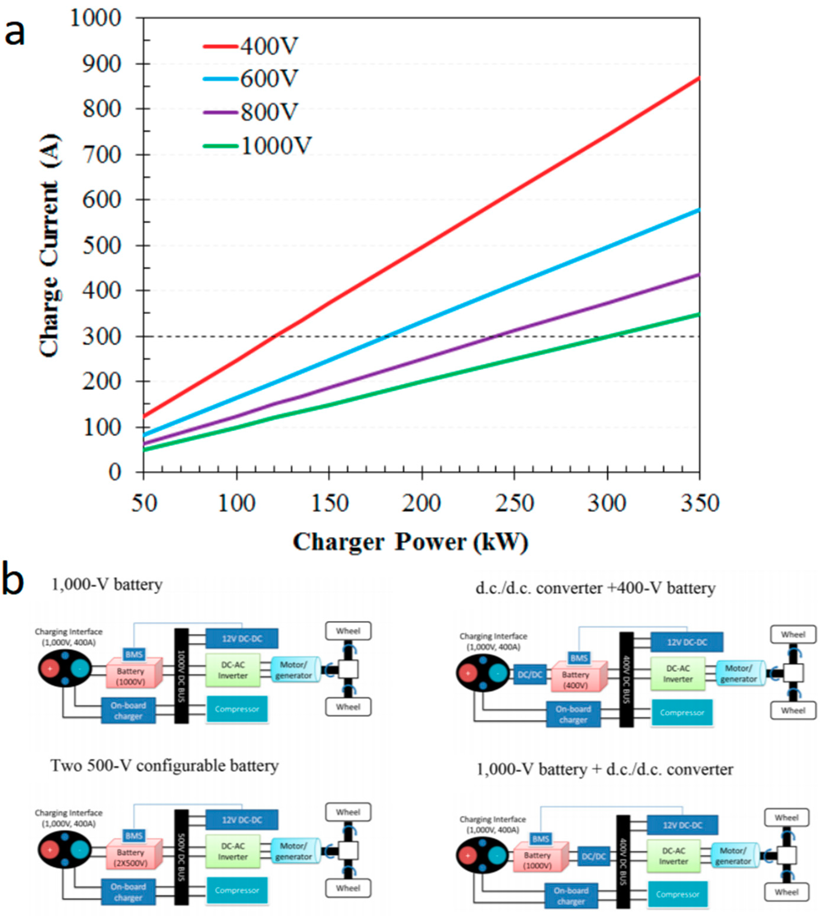
2.2. Consideration in Charging Pile

The DC fast charger requires a 480 V power source, according to the electric vehicle supply equipment (EVSE) charger classifications of the Electric Vehicle Transportation Center of the US [8]. As shown in Table 3, the Tesla supercharger in the fast-charging station is also 480 V DC with 140 kW power. While extreme fast charging (XFC) (>350 kW) needs to achieve a high output voltage of over 800 V. So far, Level 1 and level 2 chargers are sufficient in most cases for daily commuting and short trips, but the XFC is required for the practicality of long range EVs [46,47]. Higher currents (>400 A) would generate more heat, increasing the thermal load on the pack cooling system. Thus, the current is preferably limited to 400 A. For the XFC system, only when the charging voltage is greater than 1000 V does the current not exceed 400 A, as shown in Figure 5a. Therefore, a high voltage not only increases the cost (it is estimated that one XFC system for a 300-mile range vehicle will cost up to $100,000) but also requires special equipment, installation procedures, permits, and costly maintenance warranties. Therefore, the existing charging system at the 1000-V level with industry-standard components and technologies is only owned by commercial customers or EV manufacturers [4]. Furthermore, some examples, as shown in Figure 5b, introduce several possible approaches to manage the high-power, intermittent demand from XFC station. XFC can potentially reduce the battery charging time to make it comparable to the typical refueling time of conventional internal combustion engine vehicles. However, this requires electrical infrastructure adapted for high power, and these chargers are quite expensive. Increased voltage will require additional insulation and creep requirements [48], which may add volume and mass to the electrical components, cables, and connectors of the vehicle. A higher battery voltage will also require a pack with more cells connected in series. This will require additional sensing and balancing circuits to monitor and balance the battery pack, as well as new materials and fuse designs to meet the low resistance requirements for high-accuracy measurements.
In addition to the charging piles themselves, the solutions to determine the location and timing of charging stations and how many chargers to allocate at each station to cope with the changing EV market should be carefully studied [49]. The choice behavior was also studied. Some studies showed that long-distance travelers have tighter charging time limits, because there is less charging activity along the rural highway corridors, while short-distance travelers can tolerate relatively long recharging times by performing other activities [50]. In the future, multiple case studies will be required to assess the scope of equipment, installation, and operating costs under various possible usage patterns.

2.3. Considerations for the Power Grid

When an EV is connected to the power network as a distributed micro energy storage unit, the distribution network will change from a radial network to a complex network with interconnections between distributed controllable micro energy storage units and users [52]. The changes of operating characteristics will affect the safe and economic operation of the power grid [53]. With the rapid increase in the number of EVs and charging stations, EVs will become a new type of important load in the future. Considering the randomness of the EV charging time, the effects on the power grid—such as load balancing, power capacity, power quality, and environmental influence—must be further studied and minimized [54]. The power of one fast-charging pile has exceeded the power consumption of dozens of households. Therefore, each charging station needs to set up a 10-kV transformer separately, while not all distribution networks in a region have room for 10-kV substations. From the perspective of the power grid load, there is a gap between instantaneous power and the total load, and increases in the power grid capacity and corresponding technology with intelligent coordination and matching must be improved [55].
According to the national standard in China, charging stations cannot be directly set up in the original residential power network. To ensure overall security, the maximum power of operating DC charging piles will be limited in some areas to avoid excessive fluctuations in the power grid caused by instantaneous high-power charging. To avoid an increase in the peak load power of the load profile caused by uncontrolled EV charging, load shifting or peak shaving is performed [56]. Other options, such as tariff charging or smart charging and different centrally managed charging strategies, have been researched [57]. For example, a management model of home energy including micro-generators and an energy storage system has been proposed, as shown in Figure 6. The simulation results show that the proposed home energy management model has lower cost and better economy. In addition, this strategy provides a feasible solution for the optimal energy management of residential energy users. In the near future, with the comprehensive development of fast-charging technology for EV batteries, power management technology will have more breakthroughs [50]. In addition, the interdependencies of power and transportation networks should arouse concern and the optimization methods to deal with the computational complexity of them, and their role in future smart cities is well worth developing [58].

3. Microscopic Challenges in EV Fast Charging

3.1. Effect on Battery Cells

3.1.1. Anode

Although we can realize fast charging by improving macro battery technology, such fast charging is not desirable. In terms of battery mechanics, large current charging will lead to lithium plating on the graphite anode, resulting in a quick, irreversible capacity fade [59]. This can be attributed to the fact that traditional graphite anodes can only accept lithium ions at a slow charging rate limited by the low diffusion coefficient of lithium ions. As shown in Figure 7a, it is easy for graphite to produce lithium plating since the insertion of lithium into graphite occurs within a very narrow potential range (65–200 mV vs. Li/Li+) that is close to the thermodynamic potential of the Li/Li+, especially at high insertion levels. Lithium plating occurs in charge conditions. In terms of mechanisms, lithium plating can be subjected to two different processes: charge transfer and lithium solid diffusion [60]. Lithium plating occurs in charge conditions. In terms of mechanism, lithium plating can be subjected to two different limitation: charge transfer limitation and the solid diffusion limitation (Figure 7a insert). Briefly speaking, lithium plating originates from high-charge currents and the large concentration gradients of Li+ [61]. As shown in Figure 7b, the total charging current is divided into an intercalation current and lithium plating current. During charging, due to the decreasing of lithium ions vacancy and the limited solid-state diffusion in graphite, the charging current for Li intercalation is gradually reduced. Simultaneously, as the transport rate of lithium ions from the electrolyte is higher than the intercalation rate of lithium ions, the accumulation of lithium ions on the graphite surface increases, driving the anode potential to below 0 V, resulting in lithium plating. Lithium plating could result in the loss of capacity, an increase in resistance, and a potential short circuit [59].
The effective detection of lithium plating to avoid the thermal runaway of the battery—which is caused by lithium plating—is a necessary measure to ensure the safe operation of batteries, especially for fast-charging batteries. When lithium plating occurred, the surface potential of the graphite was dominated by the deposition of lithium metal and then remained constant [61]. Using that, the battery life could be estimated by measuring the changes in battery voltage [62,63], especially at high charging/discharging current. Figure 7b summarizes the study on in situ detection of lithium plating on the graphite anode. Additionally, for commercial lithium-ion batteries, impedance spectroscopy is an in-operando method for the detection of lithium plating on the surface of graphite anodes [64,65]. The change in cell thickness is also a nondestructive detection indicator of the lithium plating in pouch cells [66]. Recently, Raman spectroscopy was demonstrated as a sensitive method to identify lithium nucleation and map lithium deposition [67].

3.1.2. Cathode, Electrolyte, and Current Collector

It may not seem that the cathode is the limit for fast-charging in a single cell, since it has a higher Li+ diffusion coefficient than that of the anode. When Li+ diffuse into and out of the host lattice of cathode, the stress-associated volume changes and concentration gradients can be induced, but the stress is not the main factor affecting battery performance deterioration when fast-charging, since some special studies showed that a slow charging rate resulted in severe disintegration of the NMC secondary particles while fast charging caused less damage [68]. Thus, whether it is slow charging or fast-charging (4–6 C), the limit from NCM is less than that from graphite due to low ionic conductivity. In fact, the reaction between the electrolyte and cathode is the real culprit during the fast-charging process [69,70]. Further study showed that the cathode still performed well at a low C-rate even after fast-charging [71], which indicated that the cathode is not the limit for fast-charging in a single cell. Developing electrolyte is truly an important direction to realize real fast-charging [9]. Some researchers have also noted that enhancing electrolyte properties is important to enable XFC within high-energy density cells. Methyl acetate (MA) and methyl propionate (MP) have been used as electrolyte additives to support fast-charging without plating [72,73]. To improve the fast-charging performance, developing 3D current collector is also a promising direction, some of the results presented point in this direction already [74,75], since the 3D current collector can increase the contact surface area between the active material and the collector and benefiting more mass loading.

3.2. Potential Solutions for Fast-Charging Battery Cells

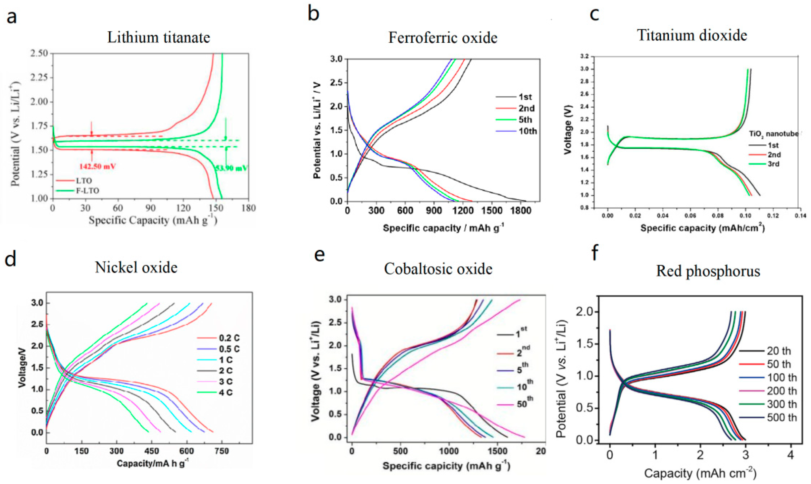
3.2.1. Electrode Materials

The lithium ion diffusion coefficient is one of the determining factors for the fast-charging performance of LIBs. In theory, lithium ions go through a multistep process of the intercalation/deintercalation of lithium ions. This process includes the diffusion of Li+ in the electrolyte, the migration of Li+ in the solid electrolyte interphase (SEI) film, and the diffusion of Li+ in the electrode material [76]. The diffusion rate of lithium ions in the solid phase is much lower than that in the liquid phase, so the diffusion rate of lithium ions in the solid phase is the decisive step of high-power charging and discharging of lithium-ion batteries [77]. As shown in Figure 8, ion diffusion impedance and the impedance related to crystal structure change accounts for a large proportion of the total impedance [78].
Fick’s second law of diffusion described the change of the concentration of substance at each point in the medium due to diffusion under unstable diffusion condition [79,80]. For LIBs, the diffusion process of lithium ions in the solid phase is relatively complex. In particular, the chemical diffusion coefficient of lithium ions will decrease sharply during the crystal structure change (phase transformation). For example, in the transition from the amorphous phase to the crystalline phase of graphite, the diffusion coefficient of lithium ions is minimized [81]. Therefore, improving the lithium ion diffusion coefficient, especially during the phase transition of the electrode materials, is of great significance for improving the fast-charging performance of a full battery.
Currently, the mainstream anode material of LIBs in the market is graphite. The graphite anode has excellent electron conductivity but a low diffusion coefficient of lithium ions (10−11–10−10 cm2/s), which seriously limits its fast-charging performance [82]. When it is charged at a high rate, a large number of lithium ions cannot be quickly inserted into the electrode body and instead precipitate on the surface of the graphite electrode, leading to Li plating, thus resulting in capacity decay and causing safety problems. As mentioned earlier, Li plating is the main problem of lithium ion batteries during fast-charging; thus, we will focus the discussion on anode materials.
Research shows that the battery should be capable of a charging speed of 4.6–6 C (as shown in Table 4, in a future supercharging mode [4]. As far as the present situation is concerned, it is difficult for graphite anode materials to adapt to super quick charging. Hard carbon and soft carbon materials have also developed in recent years; hard carbon materials have high lithium insertion potential and good reaction kinetics, while soft carbon materials have good compatibility with electrolytes. However, hard carbon and soft carbon materials have generally low efficiency and high cost; thus, they are not widely used [83]. Li4Ti5O12 is recognized as a rapidly rechargeable anode material [84], but its specific capacity is not high (175 mAh g−1), and its lithium insertion potential is relatively high (1.55 V), so overall, the energy density of the full battery is limited. Other fast-charging anode materials are also developing, such as silicon oxide [85], titanium dioxide [86], nickel dioxide [87], and various transition metal oxides [88,89,90]. In particular, the Ti–Nb–O family, such as Ti2Nb14O39 and TiNb2O7, are promising and possess good fast charging performance while offering 2D pathways for Li+ transfer [91,92,93]. Although the above-mentioned oxide anode materials have a high fast-charging performance due to their high lithium ion diffusion coefficient (~10−8 cm2/s); they have a common defect of low energy density in full cells, which is caused by their high lithiation potential, as shown in Figure 9. Silicon and silicon-based materials, the new generation of anode materials, have a relatively high gram capacity, but their inherently poor conductivity and their volume expansion in the process of charging and discharging lead to a gradual deterioration of the cycle performance, which is difficult to effectively control in a short period of time [94,95,96]. Academically, the volume expansion problem of Si/SiO can be solved by reserving space, for example, designing core–shell structure, porous structure, and so on. Industrially, it is solved by just using Si/SiO as an anode additive for graphite in a certain way compound. In this compound, for one thing, the amount of Si/SiO is very small and the effect of volume change resulted from Si/SiO is small. For another, graphite in the compound plays a role of buffering volume change to a large extent. However, just because the amount of Si/SiO in the compound is very small (about 5–10 wt %), Li plating is unavoidable for the compound, since its platform voltage of discharging is still similar to that of graphite. Compared with Si/SiO related anode, the advantage of red phosphorus related anode is the platform voltage of discharging is higher with less risk of Li plating and more safety [92].
Moreover, red phosphorus can achieve a superior rate performance at 2500 mAh g−1 and high-energy density for its relatively high lithium plating potential 0.8 V (vs Li/Li+) [101,102]. It is proposed that red phosphorus should be the key material for building next-generation fast-charging lithium-ion cells with high safety performance [103]. Although there are some problems, such as large volume expansion and low electric conductivity in the charging and discharging process, red phosphorus as a covalent molecular crystal is easier to modify in structures to overcome the above-mentioned problems in the Si, Ge, and Sn anodes [104,105]. Typically, it has been reported that Li atoms can be bindedto phosphorene with a binding energy of approximately 2.00 eV and can diffuse with high anisotropic character and low energy barriers on a phosphorene monolayer [106]. This means that red phosphorus has potential fast-charging performance resulting from a high Li+ diffusion ability as an electrode material for LIBs. Really, nanosized (from 100 to 200 nm) red phosphorene was synthesized by reacting PI3 with ethylene glycol under the conditions with cetyltrimethylammonium bromide [107]. As shown in Figure 10a, this nanosized red phosphorus displayed specific charge capacities of 200 mA h g−1 at rate 30 C. Even at a much higher charge current density of 120 A g−1 (60 C), this nanosized red phosphorene exhibited a specific capacity of 175 mA h g−1. Furthermore, some solutions to resolve the problem of volume expansion and the consequent sluggish electrode kinetics was performed. For example, as shown in Figure 10c, the P-TiO2@CNT composite present 87% capacity retention in 200 cycles at 0.2 A g−1, and 750 mAh g−1 at 10 A g−1,which can be attribute to the nanosize of red P sheets and the buffer function from carbon nanotube network. This performance makes red P is a promising anode material for high-capacity/high-rate lithium-ion batteries [108]. Other work on red phosphorus modified carbon nanotube composites [109], graphene composites [110], other composite materials [111], and the design of complex novel nanostructures [112,113] have also been reported.

3.2.2. Red Phosphorus Anode

Since researchers have proposed red phosphorus as a promising anode material that accommodates the double need of fast charging and a high-energy density to a maximum degree [108], herein, we focus on the red phosphorus anode. Professor Xiangming He’s group has made great progress on the red phosphorus anode. They were working on essentially improving the fast-charging performance of the red phosphorus anode by the combination of increasing the ion diffusion coefficient and manipulating the dopant along with strategic nanostructuring to improve the fast-charging of red phosphorus [8]. They prepared a composite of porous carbon/red phosphorus, which shows stable cycling, high reversibility and specific capacity of over 1600 mAhg−1 [111], as shown in Figure 11a. Furthermore, they developed a hybrid composite of graphite/phosphorus/carbon material by high-temperature, which shows a high reversible capacity of 500 mAhg−1 and comparable cyclability to graphite anode [113], as shown in Figure 11b. The effect of pore size distribution of the carbon on the performance of phosphorus@carbon material was also studied. It is shown that the first coulombic efficiency of phosphorus@YP-50F can reache 80% and the capacity is still stable at 1370 mAhg−1 after 100 cycles at 300 mAg−1 [114], as shown in Figure 11c. Recently, they developed the red phosphorus-based anode possessed 800 mAhg−1 with a coulombic efficiency of 99.7% [115], as shown in Figure 11d.
They are further developing and optimizing red phosphorus for a more practical application, since it should be clear that in full cell, Li inventory is fixed, even with coulombic efficiencies of the anode below 99.99%, the capacity retention of the cell will decrease extremely quick. The latest study proved that the red P-carbon had fast-charging capability and demonstrated stable cycling with a high (close 100%) coulombic efficiency at a high areal-capacity loading, which meets the standards of industrial applications, as shown in Figure 12 [103]. It is emphasized that the red phosphorus anode can match current cathodes with a very thin thickness [102]. As we know, the thinner an electrode, the shorter total transmission path for the lithium ions, thus, an increase in fast-charging. Therefore, it is proposed that the red phosphorus anode has the potential to give lithium-ion batteries the dual performance effects of a high energy density and fast charging.
Although many studies on red phosphorus anode materials focused on the synthesis methods, few people designed the crystal structure of the red phosphorus from the perspective of regulating the lithium ion diffusion coefficient to improve the fast-charging performance. The relationship between the crystal structure, the diffusion coefficient of lithium ions, and the multiplier of the red phosphorus performance has not been studied in depth. Pessimistically speaking, red phosphorus easily to absorbs water and releases toxic H3P gas, thus it is hard to produce on a large scale. It is highly desirable to develop red phosphorus as a practical anode with fast-charging performance and high power density, while preserving durability and safety.

4. Perspective

This paper describes the current situations, problems, and development directions of fast charging technology for EVs from a macroscopic perspective, including charging piles, power grids, battery systems, and microscopic perspective, mainly referring to battery materials. The challenges faced by fast charging are as follows: ability of the batteries to accept fast charging with safety guarantees, charging efficiency rate, size/weight and cost of charging piles, delivery limitations from the power grid, and total cost. Finally, it is highlighted that the essential way to solve this problem is to develop advanced electrode materials for fast-charging by improving the diffusion coefficient of lithium ions.
For vehicles and infrastructure: It should be mentioned that new insulator materials for the packs to cope with high charging voltages, such as 1000 V, and power semiconductors resistant to high heat for the charging piles should be emphasized and developed as quickly as possible. Furthermore, the charging protocol of the major electric vehicle manufacturers should unify standards as soon as possible worldwide. In addition, a new joint storage and utilization electric model should be developed to reduce the power grid burden from EV charging.
For batteries materials: In the future XFC mode, it is required that the battery cell undergoes a charging speed of 4.6 C–6 C. It is very difficult for graphite anode materials to adapt to super quick charging because of the nature of lithium plating; thus, new anode materials must be developed. Researchers have proposed that red phosphorus is a promising anode and accommodates the double need for fast-charging and high-energy density to a maximum degree.

5. Further Work

More material research and equipment design engineering are needed. For red phosphorus anode materials, we support the view that adjusting the crystal structure of the red phosphorus improves its lithium ion diffusion coefficient, and makes it suitable as a fast-charging anode material. Also, we suggest developing surface-coating processes for red phosphorus to avoid its hygroscopicity, thus accelerating the industrial application as fast-charging anode materials, in the future.

Author Contributions

Conceptualization, X.H. and Z.C.; Project administration, X.H. and L.W.; Writing—original draft, H.Z.; Writing—review and editing, L.W.

Funding

This work was funded by the Ministry of Science and Technology of China (no. 2019YFE010186), National Natural Science Foundation of China (no. U1564205), Beijing Municipal Program (no. YETP0157) and the Department of Education of Guangdong Province (no. 2016GCZX008). Research at Argonne National Laboratory was supported by U.S. Department of Energy (DOE), Vehicle Technologies Office. Argonne National Laboratory is operated for the US Department of Energy by U Chicago Argonne, LLC, under contract DE-AC02-06CH11357.

Acknowledgments

The authors thank Joint Work Plan for Research Projects under the Clean Vehicles Consortium at U.S. and China—Clean Energy Research Center (CERC-CVC2.0, 2016–2020), and thank Tsinghua University-Zhangjiagang Joint Institute for Hydrogen Energy and Lithium Ion Battery Technology.

Conflicts of Interest

The authors declare no conflict of interest.

References

  1. Dunn, B.; Kamath, H.; Tarascon, J.-M. Electrical energy storage for the grid: A battery of choices. Science 2011, 334, 928–935. [Google Scholar] [CrossRef] [PubMed]
  2. Armand, M.; Tarascon, J.-M. Building better batteries. Nature 2008, 451, 652. [Google Scholar] [CrossRef] [PubMed]
  3. Michelbacher, C.; Ahmed, S.; Bloom, I.; Burnham, A.; Carlson, B.; Dias, F.; Dufek, E.J.; Jansen, A.N.; Keyser, M.; Markel, A. Enabling fast charging–Introduction and overview. J. Power Sources 2017, 367. [Google Scholar] [CrossRef]
  4. Meintz, A.; Zhang, J.; Vijayagopal, R.; Kreutzer, C.; Ahmed, S.; Bloom, I.; Burnham, A.; Carlson, R.B.; Dias, F.; Dufek, E.J. Enabling fast charging–Vehicle considerations. J. Power Sources 2017, 367, 216–227. [Google Scholar] [CrossRef]
  5. Ahmed, S.; Bloom, I.; Jansen, A.N.; Tanim, T.; Dufek, E.J.; Pesaran, A.; Burnham, A.; Carlson, R.B.; Dias, F.; Hardy, K. Enabling fast charging–A battery technology gap assessment. J. Power Sources 2017, 367, 250–262. [Google Scholar] [CrossRef]
  6. Keyser, M.; Pesaran, A.; Li, Q.; Santhanagopalan, S.; Smith, K.; Wood, E.; Ahmed, S.; Bloom, I.; Dufek, E.; Shirk, M. Enabling fast charging–Battery thermal considerations. J. Power Sources 2017, 367, 228–236. [Google Scholar] [CrossRef]
  7. Burnham, A.; Dufek, E.J.; Stephens, T.; Francfort, J.; Michelbacher, C.; Carlson, R.B.; Zhang, J.; Vijayagopal, R.; Dias, F.; Mohanpurkar, M. Enabling fast charging–Infrastructure and economic considerations. J. Power Sources 2017, 367, 237–249. [Google Scholar] [CrossRef]
  8. Tang, Y.; Zhang, Y.; Li, W.; Ma, B.; Chen, X. Rational material design for ultrafast rechargeable lithium-ion batteries. Chem. Soc. Rev. 2015, 44, 5926–5940. [Google Scholar] [CrossRef]
  9. Liu, Y.; Zhu, Y.; Cui, Y. Challenges and opportunities towards fast-charging battery materials. Nat. Energy 2019, 4, 540–550. [Google Scholar] [CrossRef]
  10. Hesse, H.; Schimpe, M.; Kucevic, D.; Jossen, A. Lithium-ion battery storage for the grid—A review of stationary battery storage system design tailored for applications in modern power grids. Energies 2017, 10, 2107. [Google Scholar] [CrossRef]
  11. Wang, Y.; Fu, X.; Zheng, M.; Zhong, W.H.; Cao, G. Strategies for Building Robust Traffic Networks in Advanced Energy Storage Devices: A Focus on Composite Electrodes. Adv. Mater. 2019, 31, 1804204. [Google Scholar] [CrossRef] [PubMed]
  12. Eftekhari, A. The mechanism of ultrafast supercapacitors. J. Mater. Chem. A 2018, 6, 2866–2876. [Google Scholar] [CrossRef]
  13. Wang, Q.; Shaffer, C.E.; Sinha, P.K. Controlling Factors of Cell Design on Large-Format Li-Ion Battery Safety during Nail Penetration. Front. Energy Res. 2015, 3. [Google Scholar] [CrossRef] [Green Version]
  14. Colclasure, A.M.; Dunlop, A.R.; Trask, S.; Polzin, B.; Jansen, A.; Smith, K. Requirements for Enabling Extreme Fast Charging of High Energy Density Li-Ion Cells while Avoiding Lithium Plating. J. Electrochem. Soc. 2019, 166, A1412–A1424. [Google Scholar] [CrossRef]
  15. Kisu, K.; Aoyagi, S.; Nagatomo, H.; Iwama, E.; Reid, M.T.H.; Naoi, W.; Naoi, K. Internal resistance mapping preparation to optimize electrode thickness and density using symmetric cell for high-performance lithium-ion batteries and capacitors. J. Power Sources 2018, 396, 207–212. [Google Scholar] [CrossRef]
  16. Chen, Y.-S.; Chang, K.-H.; Hu, C.-C.; Cheng, T.-T. Performance comparisons and resistance modeling for multi-segment electrode designs of power-oriented lithium-ion batteries. Electrochim. Acta 2010, 55, 6433–6439. [Google Scholar] [CrossRef]
  17. Wang, C.-Y.; Zhang, G.; Ge, S.; Xu, T.; Ji, Y.; Yang, X.-G.; Leng, Y. Lithium-ion battery structure that self-heats at low temperatures. Nature 2016, 529, 515. [Google Scholar] [CrossRef]
  18. Ye, Y.; Saw, L.H.; Shi, Y.; Somasundaram, K.; Tay, A.A. Effect of thermal contact resistances on fast charging of large format lithium ion batteries. Electrochim. Acta 2014, 134, 327–337. [Google Scholar] [CrossRef]
  19. Gallagher, K.G.; Trask, S.E.; Bauer, C.; Woehrle, T.; Lux, S.F.; Tschech, M.; Lamp, P.; Polzin, B.J.; Ha, S.; Long, B. Optimizing areal capacities through understanding the limitations of lithium-ion electrodes. J. Electrochem. Soc. 2016, 163, A138–A149. [Google Scholar] [CrossRef]
  20. He, M.S.; Kollmeyer, P.J.; Haußmann, M.; Emadi, A. A Comparison of the Performance and Thermal Management Requirements of Lithium-Ion Batteries during Ultra-Fast Charging. In Proceedings of the 2018 IEEE Transportation Electrification Conference and Expo (ITEC), Long Beach, CA, USA, 13–15 June 2018; pp. 675–680. [Google Scholar]
  21. Schmidt, A.; Smith, A.; Ehrenberg, H. Power capability and cyclic aging of commercial, high power lithium ion battery cells with respect to different cell designs. J. Power Sources 2019, 425, 27–38. [Google Scholar] [CrossRef]
  22. Jiang, F.; Peng, P.; Sun, Y. Thermal analyses of LiFePO4/graphite battery discharge processes. J. Power Sources 2013, 243, 181–194. [Google Scholar] [CrossRef]
  23. Tanim, T.R.; Shirk, M.G.; Bewley, R.L.; Dufek, E.J.; Liaw, B.Y. Fast charge implications: Pack and cell analysis and comparison. J. Power Sources 2018, 381, 56–65. [Google Scholar] [CrossRef]
  24. Malik, M.; Dincer, I.; Rosen, M.A.; Mathew, M.; Fowler, M. Thermal and electrical performance evaluations of series connected Li-ion batteries in a pack with liquid cooling. Appl. Therm. Eng. 2018, 129, 472–481. [Google Scholar] [CrossRef]
  25. Li, K.; Yan, J.; Chen, H.; Wang, Q. Water cooling based strategy for lithium ion battery pack dynamic cycling for thermal management system. Appl. Therm. Eng. 2018, 132, 575–585. [Google Scholar] [CrossRef]
  26. Chung, Y.; Kim, M.S. Thermal analysis and pack level design of battery thermal management system with liquid cooling for electric vehicles. Energy Convers. Manag. 2019, 196, 105–116. [Google Scholar] [CrossRef]
  27. Lu, Z.; Meng, X.; Wei, L.; Hu, W.; Zhang, L.; Jin, L. Thermal management of densely-packed EV battery with forced air cooling strategies. Energy Procedia 2016, 88, 682–688. [Google Scholar] [CrossRef]
  28. Kizilel, R.; Sabbah, R.; Selman, J.R.; Al-Hallaj, S. An alternative cooling system to enhance the safety of Li-ion battery packs. J. Power Sources 2009, 194, 1105–1112. [Google Scholar] [CrossRef]
  29. Amietszajew, T.; McTurk, E.; Fleming, J.; Bhagat, R. Understanding the limits of rapid charging using instrumented commercial 18650 high-energy Li-ion cells. Electrochim. Acta 2018, 263, 346–352. [Google Scholar] [CrossRef]
  30. Soltanimehr, M.; Afrand, M. Thermal conductivity enhancement of COOH-functionalized MWCNTs/ethylene glycol–water nanofluid for application in heating and cooling systems. Appl. Therm. Eng. 2016, 105, 716–723. [Google Scholar] [CrossRef]
  31. Nazari, M.; Karami, M.; Ashouri, M. Comparing the thermal performance of water, Ethylene Glycol, Alumina and CNT nanofluids in CPU cooling: Experimental study. Exp. Therm. Fluid Sci. 2014, 57, 371–377. [Google Scholar] [CrossRef]
  32. Wang, Y.; Zhang, C.; Chen, Z.; Xie, J.; Zhang, X. A novel active equalization method for lithium-ion batteries in electric vehicles. Appl. Energy 2015, 145, 36–42. [Google Scholar] [CrossRef]
  33. Jarrett, A.; Kim, I.Y. Design optimization of electric vehicle battery cooling plates for thermal performance. J. Power Sources 2011, 196, 10359–10368. [Google Scholar] [CrossRef]
  34. Jiang, J.; Liu, Q.; Zhang, C.; Zhang, W. Evaluation of Acceptable Charging Current of Power Li-Ion Batteries Based on Polarization Characteristics. IEEE Trans. Ind. Electron. 2014, 61, 6844–6851. [Google Scholar] [CrossRef]
  35. Shang, Y.; Zhang, C.; Cui, N.; Guerrero, J.M. A cell-to-cell battery equalizer with zero-current switching and zero-voltage gap based on quasi-resonant LC converter and boost converter. IEEE Trans. Power Electron. 2014, 30, 3731–3747. [Google Scholar] [CrossRef]
  36. Hannan, M.; Hoque, M.; Ker, P.; Begum, R.; Mohamed, A. Charge equalization controller algorithm for series-connected lithium-ion battery storage systems: Modeling and applications. Energies 2017, 10, 1390. [Google Scholar] [CrossRef]
  37. Liu, K.; Hu, X.; Yang, Z.; Xie, Y.; Feng, S. Lithium-ion battery charging management considering economic costs of electrical energy loss and battery degradation. Energy Convers. Manag. 2019, 195, 167–179. [Google Scholar] [CrossRef]
  38. Keil, P.; Jossen, A. Charging protocols for lithium-ion batteries and their impact on cycle life—An experimental study with different 18650 high-power cells. J. Energy Storage 2016, 6, 125–141. [Google Scholar] [CrossRef]
  39. Ayoub, E.; Karami, N. Review on the charging techniques of a Li-Ion battery. In Proceedings of the 2015 Third International Conference on Technological Advances in Electrical, Electronics and Computer Engineering (TAEECE), Beirut, Lebanon, 29 April–1 May 2015; pp. 50–55. [Google Scholar]
  40. Guo, Z.; Liaw, B.Y.; Qiu, X.; Gao, L.; Zhang, C. Optimal charging method for lithium ion batteries using a universal voltage protocol accommodating aging. J. Power Sources 2015, 274, 957–964. [Google Scholar] [CrossRef]
  41. García, G.; Dieckhöfer, S.; Schuhmann, W.; Ventosa, E. Exceeding 6500 cycles for LiFePO4/Li metal batteries through understanding pulsed charging protocols. J. Mater. Chem. A 2018, 6, 4746–4751. [Google Scholar] [CrossRef]
  42. Li, S.; Wu, Q.; Zhang, D.; Liu, Z.; He, Y.; Wang, Z.L.; Sun, C. Effects of pulse charging on the performances of lithium-ion batteries. Nano Energy 2019, 56, 555–562. [Google Scholar] [CrossRef]
  43. Fleury, X.; Noh, M.H.; Geniès, S.; Thivel, P.X.; Lefrou, C.; Bultel, Y. Fast-charging of Lithium Iron Phosphate battery with ohmic-drop compensation method: Ageing study. J. Energy Storage 2018, 16, 21–36. [Google Scholar] [CrossRef]
  44. Xu, M.; Wang, R.; Reichman, B.; Wang, X. Modeling the effect of two-stage fast charging protocol on thermal behavior and charging energy efficiency of lithium-ion batteries. J. Energy Storage 2018, 20, 298–309. [Google Scholar] [CrossRef]
  45. Chu, Z.; Feng, X.; Lu, L.; Li, J.; Han, X.; Ouyang, M. Non-destructive fast charging algorithm of lithium-ion batteries based on the control-oriented electrochemical model. Appl. Energy 2017, 204, 1240–1250. [Google Scholar] [CrossRef]
  46. Noh, M.; Thivel, P.; Lefrou, C.; Bultel, Y. Fast-charging of lithium iron phosphate battery with ohmic-drop compensation method. J. Energy Storage 2016, 8, 160–167. [Google Scholar] [CrossRef]
  47. Mussa, A.S.; Klett, M.; Behm, M.; Lindbergh, G.; Lindström, R.W. Fast-charging to a partial state of charge in lithium-ion batteries: A comparative ageing study. J. Energy Storage 2017, 13, 325–333. [Google Scholar] [CrossRef]
  48. Sun, X.-H.; Yamamoto, T.; Morikawa, T. Fast-charging station choice behavior among battery electric vehicle users. Transp. Res. Part D Transp. Environ. 2016, 46, 26–39. [Google Scholar] [CrossRef]
  49. Dong, X.; Mu, Y.; Xu, X.; Jia, H.; Wu, J.; Yu, X.; Qi, Y. A charging pricing strategy of electric vehicle fast charging stations for the voltage control of electricity distribution networks. Appl. Energy 2018, 225, 857–868. [Google Scholar] [CrossRef]
  50. Xie, F.; Liu, C.; Li, S.; Lin, Z.; Huang, Y. Long-term strategic planning of inter-city fast charging infrastructure for battery electric vehicles. Transp. Res. Part E Logist. Transp. Rev. 2018, 109, 261–276. [Google Scholar] [CrossRef]
  51. Michelbacher, C.J.; Ahmed, S.; Bloom, I.; Burnham, A.; Carlson, B.; Dias, F.; Dufek, E.J.; Jansen, A.N.; Keyser, M.; Markel, A. Enabling Fast Charging: A Technology Gap Assessment; Idaho National Lab.(INL): Idaho Falls, ID, USA, 2017. [Google Scholar]
  52. Funke, S.Á.; Plötz, P.; Wietschel, M. Invest in fast-charging infrastructure or in longer battery ranges? A cost-efficiency comparison for Germany. Appl. Energy 2019, 235, 888–899. [Google Scholar] [CrossRef]
  53. Blasius, E.; Wang, Z. Effects of charging battery electric vehicles on local grid regarding standardized load profile in administration sector. Appl. Energy 2018, 224, 330–339. [Google Scholar] [CrossRef]
  54. Zheng, M.; Wang, X.; Meinrenken, C.J.; Ding, Y. Economic and environmental benefits of coordinating dispatch among distributed electricity storage. Appl. Energy 2018, 210, 842–855. [Google Scholar] [CrossRef]
  55. Xiong, Y.; Wang, B.; Chu, C.-C.; Gadh, R. Vehicle grid integration for demand response with mixture user model and decentralized optimization. Appl. Energy 2018, 231, 481–493. [Google Scholar] [CrossRef]
  56. Shirazi, E.; Jadid, S. Cost reduction and peak shaving through domestic load shifting and DERs. Energy 2017, 124, 146–159. [Google Scholar] [CrossRef]
  57. Pearre, N.S.; Ribberink, H. Review of research on V2X technologies, strategies, and operations. Renew. Sustain. Energy Rev. 2019, 105, 61–70. [Google Scholar] [CrossRef]
  58. Amini, M.H. A panorama of interdependent power systems and electrified transportation networks. In Sustainable Interdependent Networks II; Springer: Berlin, Germany, 2019; pp. 23–41. [Google Scholar]
  59. Burns, J.; Stevens, D.; Dahn, J. In-situ detection of lithium plating using high precision coulometry. J. Electrochem. Soc. 2015, 162, A959–A964. [Google Scholar] [CrossRef]
  60. Legrand, N.; Knosp, B.; Desprez, P.; Lapicque, F.; Raël, S. Physical characterization of the charging process of a Li-ion battery and prediction of Li plating by electrochemical modelling. J. Power Sources 2014, 245, 208–216. [Google Scholar] [CrossRef]
  61. Uhlmann, C.; Illig, J.; Ender, M.; Schuster, R.; Ivers-Tiffée, E. In situ detection of lithium metal plating on graphite in experimental cells. J. Power Sources 2015, 279, 428–438. [Google Scholar] [CrossRef]
  62. Yang, X.-G.; Ge, S.; Liu, T.; Leng, Y.; Wang, C.-Y. A look into the voltage plateau signal for detection and quantification of lithium plating in lithium-ion cells. J. Power Sources 2018, 395, 251–261. [Google Scholar] [CrossRef]
  63. Matasso, A.; Wetz, D.; Liu, F. The Effects of Internal Pressure Evolution on the Aging of Commercial Li-Ion Cells. J. Electrochem. Soc. 2015, 162, A92–A97. [Google Scholar] [CrossRef]
  64. Schindler, S.; Bauer, M.; Petzl, M.; Danzer, M.A. Voltage relaxation and impedance spectroscopy as in-operando methods for the detection of lithium plating on graphitic anodes in commercial lithium-ion cells. J. Power Sources 2016, 304, 170–180. [Google Scholar] [CrossRef]
  65. Lee, H.-M.; Kim, H.-M.; Oh, S.-T.; Sol-Nip, L. Detection Method of LI Plating, Method and Apparatus for Charging Secondary Battery and Secondary Battery System Using the Same; LG Chem Ltd: Seoul, Korean, 2018. [Google Scholar]
  66. Bitzer, B.; Gruhle, A. A new method for detecting lithium plating by measuring the cell thickness. J. Power Sources 2014, 262, 297–302. [Google Scholar] [CrossRef]
  67. Fonseca Rodrigues, M.-T.; Maroni, V.A.; Gosztola, D.J.; Yao, K.P.C.; Kalaga, K.; Shkrob, I.A.; Abraham, D.P. Lithium Acetylide: A Spectroscopic Marker for Lithium Deposition During Fast Charging of Li-Ion Cells. ACS Appl. Energy Mater. 2019, 2, 873–881. [Google Scholar] [CrossRef]
  68. Xu, R.; de Vasconcelos, L.; Shi, J.; Li, J.; Zhao, K. Disintegration of meatball electrodes for LiNix MnyCozO2 cathode materials. Exp. Mech. 2018, 58, 549–559. [Google Scholar] [CrossRef]
  69. Li, G.; Zhang, Z.; Huang, Z.; Yang, C.; Zuo, Z.; Zhou, H. Understanding the accumulated cycle capacity fade caused by the secondary particle fracture of LiNi1-xy CoxMnyO2 cathode for lithium ion batteries. J. Solid State Electrochem. 2017, 21, 673–682. [Google Scholar] [CrossRef]
  70. Watanabe, S.; Kinoshita, M.; Hosokawa, T.; Morigaki, K.; Nakura, K. Capacity fade of LiAlyNi1−x−yCoxO2 cathode for lithium-ion batteries during accelerated calendar and cycle life tests (surface analysis of LiAlyNi1−x−yCoxO2 cathode after cycle tests in restricted depth of discharge ranges). J. Power Sources 2014, 258, 210–217. [Google Scholar] [CrossRef]
  71. Keyser, M.; Smith, K.; Santhanagopalan, S.; Usseglio-Viretta, F.; Colclasure, A. Extreme Fast Charging (National Renewable Energy Laboratory). X-CEL: eXtreme. Fast Charg. Cell Eval. Lithium-Ion. Batter. 2018, 163, 10. [Google Scholar]
  72. Logan, E.; Tonita, E.M.; Gering, K.; Li, J.; Ma, X.; Beaulieu, L.; Dahn, J. A study of the physical properties of Li-Ion battery electrolytes containing esters. J. Electrochem. Soc. 2018, 165, A21–A30. [Google Scholar] [CrossRef]
  73. Ma, X.; Arumugam, R.S.; Ma, L.; Logan, E.; Tonita, E.; Xia, J.; Petibon, R.; Kohn, S.; Dahn, J. A study of three ester co-solvents in lithium-ion cells. J. Electrochem. Soc. 2017, 164, A3556–A3562. [Google Scholar] [CrossRef]
  74. Poetz, S.; Fuchsbichler, B.; Schmuck, M.; Koller, S. Development of a 3d current collector for the positive electrode in lithium-ion batteries. J. Appl. Electrochem. 2014, 44, 989–994. [Google Scholar] [CrossRef]
  75. Sun, H.; Zhu, J.; Baumann, D.; Peng, L.; Xu, Y.; Shakir, I.; Huang, Y.; Duan, X. Hierarchical 3D electrodes for electrochemical energy storage. Nat. Rev. Mater. 2018. [Google Scholar] [CrossRef]
  76. Ramasubramanian, A.; Yurkiv, V.; Foroozan, T.; Ragone, M.; Shahbazian-Yassar, R.; Mashayek, F. Lithium Diffusion Mechanism through Solid-Electrolyte Interphase (SEI) In Rechargeable Lithium Batteries. J. Phys. Chem. C 2019. [Google Scholar] [CrossRef]
  77. Goriparti, S.; Miele, E.; De Angelis, F.; Di Fabrizio, E.; Zaccaria, R.P.; Capiglia, C. Review on recent progress of nanostructured anode materials for Li-ion batteries. J. Power Sources 2014, 257, 421–443. [Google Scholar] [CrossRef] [Green Version]
  78. Macdonald, J.R.; Barsoukov, E. Impedance spectroscopy: Theory, experiment, and applications. History 2005, 1, 1–13. [Google Scholar]
  79. Zheng, K.; Świerczek, K. Possibility of determination of transport coefficients D and k from relaxation experiments for sphere-shaped powder samples. Solid State Ion. 2018, 323, 157–165. [Google Scholar] [CrossRef]
  80. Maiza, M.; Mammeri, Y.; Nguyen, D.A.; Legrand, N.; Desprez, P.; Franco, A.A. Evaluating the impact of transport inertia on the electrochemical response of lithium ion battery single particle models. J. Power Sources 2019, 423, 263–270. [Google Scholar] [CrossRef]
  81. Wang, Q.; Li, H.; Huang, X.; Chen, L. Determination of chemical diffusion coefficient of lithium ion in graphitized mesocarbon microbeads with potential relaxation technique. J. Electrochem. Soc. 2001, 148, A737–A741. [Google Scholar] [CrossRef]
  82. Yang, H.; Bang, H.J.; Prakash, J. Evaluation of electrochemical interface area and lithium diffusion coefficient for a composite graphite anode. J. Electrochem. Soc. 2004, 151, A1247–A1250. [Google Scholar] [CrossRef]
  83. Zhao, H.; Gao, Y.; Wang, J.; Chen, C.; Chen, D.; Wang, C.; Ciucci, F. Egg yolk-derived phosphorus and nitrogen dual doped nano carbon capsules for high-performance lithium ion batteries. Mater. Lett. 2016, 167, 93–97. [Google Scholar] [CrossRef]
  84. Wang, Y.; Zhang, Y.-X.; Yang, W.-J.; Jiang, S.; Hou, X.-W.; Guo, R.; Liu, W.; Huang, P.; Lu, J.; Gu, H.-T. Enhanced Rate Performance of Li4Ti5O12 Anode for Advanced Lithium Batteries. J. Electrochem. Soc. 2019, 166, A5014–A5018. [Google Scholar] [CrossRef]
  85. Yang, N.-H.; Wu, Y.-S.; Chou, J.; Wu, H.-C.; Wu, N.-L. Silicon oxide-on-graphite planar composite synthesized using a microwave-assisted coating method for use as a fast-charging lithium-ion battery anode. J. Power Sources 2015, 296, 314–317. [Google Scholar] [CrossRef]
  86. Cui, J.; Yao, S.; Kim, J.-K. Recent progress in rational design of anode materials for high-performance Na-ion batteries. Energy Storage Mater. 2017, 7, 64–114. [Google Scholar] [CrossRef]
  87. Hwang, S.-G.; Kim, G.-O.; Yun, S.-R.; Ryu, K.-S. NiO nanoparticles with plate structure grown on graphene as fast charge–discharge anode material for lithium ion batteries. Electrochim. Acta 2012, 78, 406–411. [Google Scholar] [CrossRef]
  88. Saadat, S.; Zhu, J.; Sim, D.H.; Hng, H.H.; Yazami, R.; Yan, Q. Coaxial Fe3O4/CuO hybrid nanowires as ultra fast charge/discharge lithium-ion battery anodes. J. Mater. Chem. A 2013, 1, 8672–8678. [Google Scholar] [CrossRef]
  89. Kim, N.Y.; Lee, G.; Choi, J. Fast-Charging and High Volumetric Capacity Anode Based on Co3O4/CuO@ TiO2 Composites for Lithium-Ion Batteries. Chem. A Eur. J. 2018, 24, 19045–19052. [Google Scholar] [CrossRef]
  90. Wang, L.; Ding, K.; Wei, B.; Li, C.; Shi, X.; Zhang, Y.; He, X. Leaf-like α-Fe2O3 micron-particle: Preparation and its usage as anode materials for lithium ion batteries. Mater. Chem. Phys. 2018, 207, 58–66. [Google Scholar] [CrossRef]
  91. Lin, C.; Deng, S.; Kautz, D.J.; Xu, Z.; Liu, T.; Li, J.; Wang, N.; Lin, F. Intercalating Ti2Nb14O39 Anode Materials for Fast-Charging, High-Capacity and Safe Lithium–Ion Batteries. Small 2017, 13, 1702903. [Google Scholar] [CrossRef]
  92. Park, H.; Wu, H.B.; Song, T.; Lou, X.W.; Paik, U. Porosity-controlled TiNb2O7 microspheres with partial nitridation as a practical negative electrode for high-power lithium-ion batteries. Adv. Energy Mater. 2015, 5, 1401945. [Google Scholar] [CrossRef]
  93. Augustyn, V.; Come, J.; Lowe, M.A.; Kim, J.W.; Taberna, P.-L.; Tolbert, S.H.; Abruña, H.D.; Simon, P.; Dunn, B. High-rate electrochemical energy storage through Li+ intercalation pseudocapacitance. Nat. Mater. 2013, 12, 518. [Google Scholar] [CrossRef]
  94. Xiao, Q.; Gu, M.; Yang, H.; Li, B.; Zhang, C.; Liu, Y.; Liu, F.; Dai, F.; Yang, L.; Liu, Z. Inward lithium-ion breathing of hierarchically porous silicon anodes. Nat. Commun. 2015, 6, 8844. [Google Scholar] [CrossRef]
  95. Jin, Y.; Zhu, B.; Lu, Z.; Liu, N.; Zhu, J. Challenges and Recent Progress in the Development of Si Anodes for Lithium-Ion Battery. Adv. Energy Mater. 2017, 7, 1700715. [Google Scholar] [CrossRef]
  96. Ali, I.; Tippabhotla, S.K.; Radchenko, I.; Al-Obeidi, A.; Stan, C.V.; Tamura, N.; Budiman, A.S. Probing Stress States in Silicon Nanowires During Electrochemical Lithiation Using In Situ Synchrotron X-Ray Microdiffraction. Front. Energy Res. 2018, 6. [Google Scholar] [CrossRef]
  97. Jiang, Y.; Jiang, Z.-J.; Yang, L.; Cheng, S.; Liu, M. A high-performance anode for lithium ion batteries: Fe3O4 microspheres encapsulated in hollow graphene shells. J. Mater. Chem. A 2015, 3, 11847–11856. [Google Scholar] [CrossRef]
  98. Ryu, W.-H.; Nam, D.-H.; Ko, Y.-S.; Kim, R.-H.; Kwon, H.-S. Electrochemical performance of a smooth and highly ordered TiO2 nanotube electrode for Li-ion batteries. Electrochim. Acta 2012, 61, 19–24. [Google Scholar] [CrossRef]
  99. Wang, X.; Sun, L.; Sun, X.; Li, X.; He, D. Size-controllable porous NiO electrodes for high-performance lithium ion battery anodes. Mater. Res. Bull. 2017, 96, 533–537. [Google Scholar] [CrossRef]
  100. Li, L.; Zhang, Z.; Ren, S.; Zhang, B.; Yang, S.; Cao, B. Construction of hollow Co3O4 cubes as a high-performance anode for lithium ion batteries. New J. Chem. 2017, 41, 7960–7965. [Google Scholar] [CrossRef]
  101. Zhu, G.L.; Zhao, C.Z.; Huang, J.Q.; He, C.; Zhang, J.; Chen, S.; Xu, L.; Yuan, H.; Zhang, Q. Fast Charging Lithium Batteries: Recent Progress and Future Prospects. Small 2019, 1805389. [Google Scholar] [CrossRef]
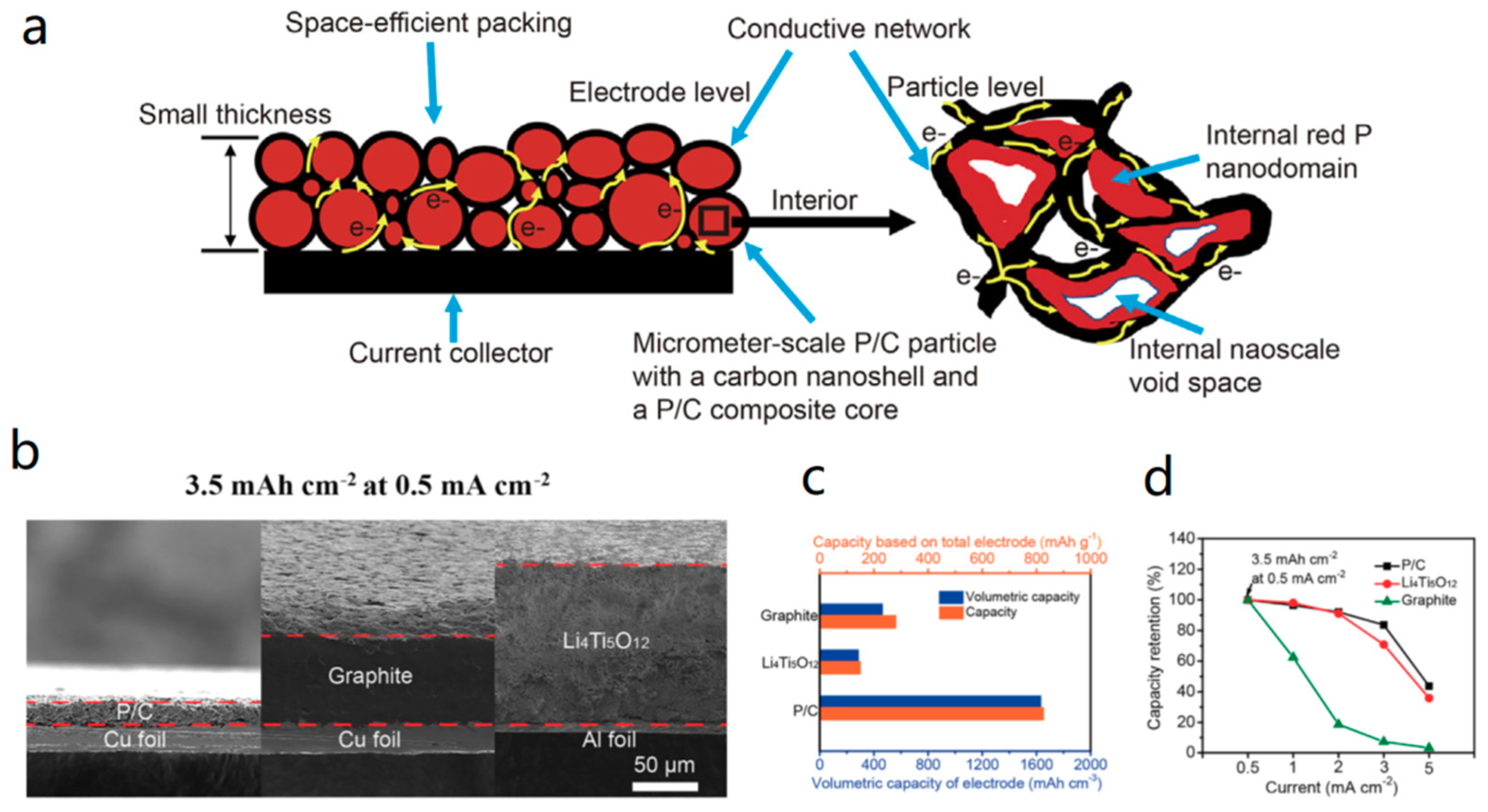
  102. Sun, Y.; Wang, L.; Li, Y.; Li, Y.; Lee, H.R.; Pei, A.; He, X.; Cui, Y. Design of Red Phosphorus Nanostructured Electrode for Fast-Charging Lithium-Ion Batteries with High Energy Density. Joule 2019. [Google Scholar] [CrossRef]
  103. Liu, Y.; Zhang, A.; Shen, C.; Liu, Q.; Cao, X.; Ma, Y.; Chen, L.; Lau, C.; Chen, T.-C.; Wei, F. Red phosphorus nanodots on reduced graphene oxide as a flexible and ultra-fast anode for sodium-ion batteries. ACS Nano 2017, 11, 5530–5537. [Google Scholar] [CrossRef]
  104. Wu, Y.; Hu, S.; Xu, R.; Wang, J.; Peng, Z.; Zhang, Q.; Yu, Y. Boosting potassium-ion battery performance by encapsulating red phosphorus in free-standing nitrogen-doped porous hollow carbon nanofibers. Nano Lett. 2019, 19, 1351–1358. [Google Scholar] [CrossRef]
  105. Khalid, M.; Varela, H. A general potentiodynamic approach for red phosphorus and sulfur nanodot incorporation on reduced graphene oxide sheets: Metal-free and binder-free electrodes for supercapacitor and hydrogen evolution activities. J. Mater. Chem. A 2018, 6, 3141–3150. [Google Scholar] [CrossRef]
  106. Sibari, A.; Marjaoui, A.; Lakhal, M.; Kerrami, Z.; Kara, A.; Benaissa, M.; Ennaoui, A.; Hamedoun, M.; Benyoussef, A.; Mounkachi, O. Phosphorene as a promising anode material for (Li/Na/Mg)-ion batteries: A first-principle study. Sol. Energy Mater. Sol. Cells 2018, 180, 253–257. [Google Scholar] [CrossRef]
  107. Chang, W.-C.; Tseng, K.-W.; Tuan, H.-Y. Solution synthesis of iodine-doped red phosphorus nanoparticles for lithium-ion battery anodes. Nano Lett. 2017, 17, 1240–1247. [Google Scholar] [CrossRef] [PubMed]
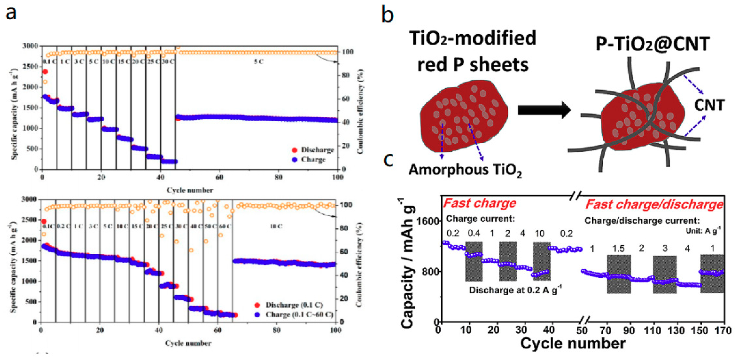
  108. Sun, L.; Zhang, Y.; Si, H.; Zhang, Y.; Liu, J.; Liu, J.; Zhang, Y. TiO2-modified red phosphorus nanosheets entangled in carbon nanotubes for high performance lithium ion batteries. Electrochim. Acta 2019, 297, 319–327. [Google Scholar] [CrossRef]
  109. Yuan, D.; Cheng, J.; Qu, G.; Li, X.; Ni, W.; Wang, B.; Liu, H. Amorphous red phosphorous embedded in carbon nanotubes scaffold as promising anode materials for lithium-ion batteries. J. Power Sources 2016, 301, 131–137. [Google Scholar] [CrossRef]
  110. Yu, Z.; Song, J.; Gordin, M.L.; Yi, R.; Tang, D.; Wang, D. Phosphorus-graphene nanosheet hybrids as lithium-ion anode with exceptional high-temperature cycling stability. Adv. Sci. 2015, 2, 1400020. [Google Scholar] [CrossRef]
  111. Wang, L.; He, X.; Li, J.; Sun, W.; Gao, J.; Guo, J.; Jiang, C. Nano-Structured Phosphorus Composite as High-Capacity Anode Materials for Lithium Batteries. Angew. Chem. 2012, 124, 9168–9171. [Google Scholar] [CrossRef]
  112. Park, C.M.; Sohn, H.J. Black phosphorus and its composite for lithium rechargeable batteries. Adv. Mater. 2007, 19, 2465–2468. [Google Scholar] [CrossRef]
  113. Bai, A.; Wang, L.; Li, J.; He, X.; Wang, J.; Wang, J. Composite of graphite/phosphorus as anode for lithium-ion batteries. J. Power Sources 2015, 289, 100–104. [Google Scholar] [CrossRef]
  114. Li, J.; Wang, L.; He, X.; Wang, J. Effect of pore size distribution of carbon matrix on the performance of phosphorus@ carbon material as anode for lithium-ion batteries. ACS Sustain. Chem. Eng. 2016, 4, 4217–4223. [Google Scholar] [CrossRef]
  115. Wang, L.; Zhou, Z.; Li, J.; He, X. Red phosphorus composite anodes for Li-ion batteries. Ionics 2018, 24, 303–308. [Google Scholar] [CrossRef]
Figure 1. Overview to functional blocks of a utility-scale battery storage system [4].
Energies 12 03897 g001
Figure 2. The summary of relationship between Rion and electrode thickness (a) [15]. Discharge capacity as a function of electrode loading (mAh/cm2) and charge rate (b) and photos of lithium deposits on representative graphite electrodes (c) [19]. Constructions of the conventional electrode design and center-tab design (The left is named cell A and the right is named cell B) (d); discharge profiles (1 C, 5 A, 10 A, 15 A, and 20 A) of cell #A and #B (e) [16]. Reproduced by permission of Royal Society of Chemistry, Elsevier, and The Electrochemical Society.
Energies 12 03897 g002
Figure 3. Design of pouch cell electrode (upper); distribution of temperature at nine cross-sectioned surfaces in cell composite volume at the end of 6 C constant charge: (a) ND cell, (b) CT cell, (c) ST cell, (d) WS cell (bottom) [6]. Reproduced by permission of Elsevier.
Energies 12 03897 g003
Figure 4. Heat generation normalized on a cell basis for a single cell and a 10-cell lithium-iron-phosphate module [6] (a); Tesla Model 3 Wins On Innovative Simplicity (htps://seekingalpha.com/article/3975416-tesla-model-3-wins-innovative-simplicity) (b); Block diagram for equalization [32] (c). Reproduced by permission of Elsevier.
Energies 12 03897 g004
Figure 5. Charge current with respect to charge power for different battery pack voltages. The 400 V configuration shown in red is representative of a typical EV battery pack today (a) [51]; options for 1000 V BEV architectures (b) [4]. Reproduced by permission of Elsevier.
Energies 12 03897 g005
Figure 6. The proposed architecture [49]. Reproduced by permission of Springer.
Energies 12 03897 g006
Figure 7. Schematic representation of Li plating occurrence (a); schematic illustration of Li plating occurring at the surface of the negative active particle (an insert) [60]; schematic illustration of the separation of the charging current into plating and intercalation currents during different states of charging. Depending on Li surface concentration and applied current, the charging current splits into different contributions from plating and intercalation (b) [61]. Reproduced by permission of Elsevier.
Energies 12 03897 g007
Figure 8. Typical impedance spectra of intercalation material [78]. Reproduced by permission of Wiley.
Energies 12 03897 g008
Figure 9. Charge–discharge curves of lithium titanate [84] (a), ferroferric oxide [97] (b), tatanium dioxide [98] (c), nickel oxide [99] (d), cobaltosic oxide [100] (e), and red phosphors [92] (f). Reproduced by permission of Royal Society of Chemistry, Elsevier, The Electrochemical Society, and Wiley.
Energies 12 03897 g009
Figure 10. Rate performance of RPNPs electrode at various rates [107] (a). Structure of P-TiO2@CNT [108] (b). Rate performance of P-TiO2@CNT [108] (c). Reproduced by permission of Royal Society of American Chemical Society and Elsevier.
Energies 12 03897 g010
Figure 11. Cycle performance of the phosphorus/porous carbon composite in the electrolyte of 1m LiPF6/EC+DMC+EMC [111] (a). Variations of coulombic efficiency and charge/discharge capacity with cycles for the electrochemical performance of graphite/P@C composite [113] (b). Cycling performance of P@YP-50F [114] (c). Cycling performance of the red phosphorus composite electrode in rechargeable lithium batteries. The electrode disk is ϕ7 mm diameter, equal to 0.38 cm2. The loading of the red phosphorus composite is 5.72 mg cm−2 [115] (d). Reproduced by permission of Elsevier, The Electrochemical Society, Wiley and Springer.
Energies 12 03897 g011
Figure 12. Schematic of material choice and structure for fast-charging LIBs [103] (a). Comparison of the thicknesses and weights [102] (b); and capacities and volumetric capacities based on the total electrode (active material, binder, and carbon) for P/C, graphite, and Li4Ti5O12 electrodes with the same areal capacity 3.5 mAh cm2 at 0.5 mA cm2) [102] (c). Comparison of capacity retentions for P/C, commercial Li4Ti5O12, and graphite electrodes with the same areal capacity of 3.5 mAh cm2 at 0.5 mA cm2. All the electrodes comprise 90 wt % materials, 5 wt % binder, and 5 wt % carbon black [102] (d). Reproduced by permission of Springer.
Energies 12 03897 g012
Table 1. Bat PaC simulation comparing the effects of charging time on the required anode thickness, the heat generation in the pack and the resulting temperature rise, the pack cost, and the incremental cost of charging faster than 1-C (60 min) rate. Cell Chemistry: NMC622-Graphite, Pack Energy: 85 kWh; Rated Power (10 s burst): 300 kW; MACD (Maximum Allowable Current Density): 4 mA cm2; no. of cells per pack: 240 [5]. Reproduced by permission of Elsevier.
Charging Time, SOC = 80%, minutes81023475361
Charging Time, SOC = 60%, minutes5715303439
Charger Power, needed, kW6014611991008877
Anode Thickness, um1419438798103
Heat Generated during Charge, kWh, per pack2.352.201.891.771.751.45
Post-Charge Cell, SOC = 80%, Temperature, °C22.424.425.926.426.419.4
Cell Mass, kg2.752.401.741.491.461.45
Cell Cost to Original Equipment Manufacturer, $per kWh$229$196$132$107$104$103
Cost Difference, $per kWh$126$93$30$4$1$0
Table 2. Case conditions under a constant 350 kW charge [14]. Reproduced by permission of Elsevier.
Case 1Case 2Case 3Case 4
Energy density (Wh kg−1 )175300300175
Number of cells (cells)484282282484
Cell efficiency (%)70907090
Pack heat removed (Kw)215215
Heat generation per cell (W)239.9138.3411.380.7
Cooling provider per cell (W)4.1453.27.131
Heat transfer coefficient (W m−2k−1)1010010100
Table 3. Source: McCarthy, Michael. “California ZEV Policy Update.” SAE 2017 Government/Industry Meeting, Society of Automotive Engineers, 25 January 2017, Walter E. Washington Convention Center, Washington, DC. Conference Presentation. [XFC—Extra Fast Charging Li-Ion Battery Market Review 2017].
Charging ModelLevel 1 (110 V, 1.4 kW)Level 2 (220 V, 7.2 kW)DC Fast Charger (480 V, 50 kW)Tesla Super Charger (480 V, 140 kW)XFC (800 V, 1400 kW)
Range per minute of charge (miles)0.0820.422.928.1723.3
Time to charge for 200 miles (minutes)2,14341760217.5
Table 4. Timeline of BEVs and battery C-rate to support XFC. Reproduced with permission from [4].
TodayFuture
Charge Voltage400 V 400–1000 V
Charge InletCHAdeMO, SAE J1772 CCS, TeslaXFC Designed Inlet(s) for 1000 V@400 A
Vehicle400 V, 125 A, 50 kW
400 V, 350 A, 140 kW
400–800 V, 400 A, 240–320 kW
1000 V, 210–280 A, 210–280 kW
1000 V, 400 A, 400 kW
Battery1.5–2 C2.0–3.3 C3.3–4.6 C4.6–6 C

