Optimization and Exergy Analysis of Nuclear Heat Storage and Recovery


Department of Nuclear Power Plant Engineering, KEPCO International Nuclear Graduate School, 689-882 Haemaji-ro, Seosaeng-myeon, Ulju-gun, Ulsan 45014, Korea
*
Author to whom correspondence should be addressed.
Energies 2019, 12(21), 4205; https://doi.org/10.3390/en12214205
Submission received: 8 October 2019
/
Revised: 30 October 2019
/
Accepted: 1 November 2019
/
Published: 4 November 2019
(This article belongs to the Section D: Energy Storage and Application)
Abstract
:The APR1400 Nuclear Heat Storage and Recovery (NHS&R) System described here represents the conceptual design and interface of a tertiary cycle with the secondary system of the Korean nuclear reactor plant APR1400. The system is intended to reliably and efficiently store and recover thermal energy from a Nuclear Power Plant (NPP) steam system in order to allow flexible power generation using an economical and scalable design. The research incorporates a comprehensive performance analysis of three interface configurations with comparisons based on the 1st and 2nd Laws of Thermodynamics. The investigated configurations are also ranked based on impact analysis of the NHS&R System on the plant configuration and operation. Input data used in the analysis is based on calibrated thermodynamic models of the system arrangements. Results were used to select the preferred APR1400 NHS&R System design configuration as characterized by: (i) maximum system efficiency, (ii) minimized energy losses, (iii) limited impact on existing plant Systems, Structures, and Components (SSC), and (iv) limited impact on plant operations. Case 3 offers several comparative advantages including: (i) high round trip efficiency, (ii) minimal impact on existing plant and equipment, (iii) high utilization of the heat transport and storage media, and (iv) good system control options.
1. Introduction
Government policies that provide subsidies for ‘green’ energy technology are shaping energy policy in many advanced countries. Currently, the choice of scalable power generation technologies with low life cycle emissions of carbon dioxide is limited to nuclear power and the green sources of wind and solar. The latter two of these can be (i.e., wind) or are (i.e., solar) highly intermittent. Under such circumstances, development of new measures to assure the reliability and security of the power system is necessary. Beyond grid interconnections across large geographical areas (i.e., to smooth regional variability of wind-based generation), flexible and dispatchable power generation represents an essential element for electrical grids highly dependent on intermittent sources [1,2,3].
Furthermore, auction markets characterized by expanding penetration of renewable energy sources are often and predictably confronted with collapsing wholesale prices of electricity in day-ahead markets [4]. This trend is only exacerbated by closure of additional legacy facilities, to be replaced by additional intermittent sources. Thus, capital-intensive nuclear facilities may need to adopt innovative technologies that permit maximum thermal output while modulating electrical output to match market-driven pricing.
Generally, Nuclear Power Plants (NPPs) are designed to operate as baseload units due to the combination of high capital cost and complex operational constraints. Note that load following operation of NPPs, though not desirable, can be routinely employed as per current practice on the French and German grids. This mode of operation, however, fails to maximize output, principally due to curtailment of thermal output to achieve variable electrical output. In addition, the responsiveness of NPP ramp up and ramp down is constrained and additional costs associated with operator training and maintenance are expected. Load following necessarily reduces the unit capacity factor resulting in economic penalties [5,6]. Such situations provide an opportunity for NPPs to fulfill a market need by consideration of Thermal Energy Storage (TES) [7,8]. An integrated TES installation enables an NPP to efficiently vary generator output while full reactor (thermal) power is maintained. During periods of reduced demand or excessive green production, thermal energy may be stored to be recovered when dictated by demand or pricing.
Optimized thermodynamic cycles for TES when coupled to an NPP have the potential to achieve high efficiency. Optimization of storage systems integrated with the existing plant requires assessment based on both 1st Law and 2nd Law considerations (as reported in recent studies) [9]. The estimation of energy losses associated with TES thermodynamic processes can be quantified by considering irreversibility, equivalent to the rate of exergy destruction (or conversely related to entropy generation). Exergy is a measure of total available energy potential of the analyzed fluids in relation to a reference state [10]. The main processes involved in TES operation are heat transfer, fluid mixing, and fluid flow. Therefore, the main contributors to entropy generation are: (i) finite temperature difference for heat transfer, (ii) mixing of fluids of dissimilar thermal potential, and (iii) pressure drop associated with fluid friction [10]. Respecting these constraints in the design of physical equipment, optimization of the thermodynamic cycle for the TES installation must: (i) minimize temperature differences for heat transfer during storage and recovery, (ii) minimize temperature and pressure differentials for mixing processes, and (iii) to a lesser extent, minimize pressure drop for considered process paths.
Recent studies of TES technologies suitable for Light Water Reactors (LWRs) typically extract heat (i.e., storage mode) from the cycle by exporting high-pressure steam, to be returned as hot or cold condensate. Recovery operation is typically characterized by the generation of intermediate pressure steam to be used in the turbine cycle [8]. Thermodynamic evaluation of the Advanced Passive (AP1000) Pressurized Water Reactor NPP Rankine cycle coupled with TES reports a capacity factor, which is 9.8% higher than for steam bypass operation (i.e., during periods of slack demand) [11]. The proposed design considers a high temperature range (225 °C) for the cycle (i.e., steam-to-condensate, and condensate to steam). Under the recovery mode, steam is injected into the Hot Reheat (HR) steam line (downstream of the reheater). The TES thermal efficiency of heat-to-power conversion ranged from 22% to 23% [11].
Other studies have examined heat storage and recovery coupled to fossil plant turbine cycles. One evaluation examined plant performance under integration with Ruth storage (steam accumulator) for two possible steam extraction configurations. The analysis indicated 20% increase in round trip efficiency for a case characterized by minimal exergy losses associated with pressure difference between stored steam and return location [12]. Another investigation reported Rankine cycle integration using a molten salt TES installation. In this study, the focus was on minimizing exergy losses associated with thermal differences between the storage and steam cycle media [13].
A substantial number of evaluations considered supplemental solar thermal repowering of fossil power stations. Thermodynamically, this is similar to round trip TES operations in terms of the integration design. The technology aims to deploy solar power to accomplish regenerative heating that can either decrease fuel consumption or increase the generator output due to a reduction of Extraction Steam (ES) bled from the turbine. Thermodynamic analysis of one possible design of Solar Aided Power Generation (SAPG) indicated that supplying steam to supplement regenerative feedwater heating could increase plant efficiency by 6.65% [14]. Alternatively, studies of feedwater bypass to solar preheating installations quantified the improved efficiency of High Pressure (HP) Feedwater Heaters (FWHs) bypass as compared to Low Pressure (LP) FWHs bypass, in line with Carnot considerations [15]. Further investigations of the bypass configuration proposed feedwater heating by hot oil circulating in solar panel installations. Results of the first evaluation indicated higher efficiency of the plant operating FWH No. 7 bypass resulting in an increase in generator power output of approximately 10% [16]. Another study recognized the benefit of bypassing only FWHs with the highest operating parameters (FWH No. 7) as compared with the remaining heaters in terms of energy and exergy efficiency [17].
The evaluation presented here focuses on addressing challenges associated with integration of TES with the NPP secondary side, the Nuclear Heat Storage and Recovery (NHS&R) System. Multiple system configurations for interface with the 1400 MWe Korean Advanced Power Reactor (APR1400) Turbine Island (TI) were examined. Three configurations were identified as promising for detailed evaluation and are reported here. Considerations include thermodynamic system development in Performance Evaluation of Power System Efficiencies (PEPSETM) software [18], quantitative assessment of system energy and exergy performance, and the effect of NHS&R System operation on the existing plant hardware, operations, and licensing. The study aims to identify optimal design with respect to: (i) thermodynamic performance, (ii) constructability, and (iii) operability of the integrated system.
1.1. APR1400 NHS&R System Design
The principal design criteria for the NHS&R System are: (i) industrial-scale capacity, (ii) scalability, (iii) constructability, and (iv) low capital cost. Using these criteria, the proposed NHS&R System is designed as a sensible heat storage system employing synthetic oil Therminol 66 as the heat transfer and energy transport medium. Energy extracted from the nuclear steam cycle is stored in crushed Hornsfels rocks housed in insulated tanks located outside of the NPP security fence. The NHR&S System interfaces with the nuclear steam cycle via heat exchangers situated in Heat Storage and Heat Recovery Buildings (HSB and HRB) adjacent to TI building. A detailed description of the APR1400 NHS&R tertiary cycle design is reported elsewhere [19].
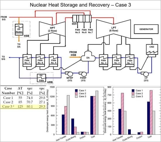
The NHS&R System is designed to be integrated with the APR1400 turbine cycle. The APR1400 is a pressurized water reactor with licensed thermal core power of 3983 MWt. The steam cycle is typical of modern LWR units with 3 stages of LP FWHs, a deaerating heater, and 3 stages of HP FWHs. Cross-around steam is dried and superheated by a two-stage Moisture Separator Reheater (MSR) [20]. A simplified diagram of the APR1400 turbine cycle including proposed NHS&R System interface locations is presented in Figure 1.
1.2. APR1400 NHS&R System Operation
Commercial NPPs are identified as prospective candidates for integration with TES due to their high capacity. The industrial scale of such facilities benefits the overall economy of such a project [21]. The proposed NHS&R system capacity storage capacity is fully scalable at very low cost and limited solely by the available land area adjacent to the NPP [22]. The constraint for system design is the charging heat rate. This is limited by design considerations for the steam flow path within the main turbine and by feedwater heating constraints at low extraction pressures.
In addition to constraints on the turbine cycle, constraints on plant operations related to Final Feedwater Temperature (FFT) are also of importance (i.e., in relation to achieving minimal impact on Reactor Coolant System (RCS) temperatures). The identified maximum energy flow for storage as extracted from the APR1400 secondary cycle is taken here as 20% of rated NSSS thermal power, equivalent to 800 MWt [23,24]. For storage on a diurnal cycle, a duration of 8 h is set, resulting in a targeted thermal storage capacity at 6400 MWh (23 × 1012 J, or 23 TJ). Note that the storage medium for the NHS&R System can be scaled to accommodate longer charging periods at very low cost.
The recovery rate is constrained by design limitations of the Main Generator. Hence, the duration for diurnal recovery operations is expected to be approximately double the duration for storage. The MVA rating of the existing main generator limits the recovery rate to approximately 11% of NSSS thermal power, corresponding to 450 MWt of additional heat transferred to the APR1400 turbine cycle.
Then nuclear power industry has significant experience in performing (thermal) power uprates of NPPs. In United States alone, over 160 applications have been licensed by the regulator [25]. In reference to this, plant modifications required to incorporate the NHS&R System are expected to retain safe operations with the increased power output.
The proposed operating cycle for the NHS&R System accounts for the turnaround time required to reverse energy flows to or from the turbine steam cycle. Initially, a transition time of one (1) hour is considered for switching between the storage and recovery operation modes. This can be reviewed with plant operators once the detailed system design is completed. The initial, proposed diurnal timeline of APR1400 NHS&R System operation is presented in Figure 2 (Case 3, typical).
2. Materials and Methods
Assessment of the thermodynamic performance of the NHS&R System considers simulation of three preselected configurations. Simulation results provide data for quantitative analysis of energy efficiency and exergy destruction to rank the configurations in terms of thermodynamic performance. Further investigations include impact analysis of the NHS&R system configurations on APR1400 plant operations and on affected SSCs. The primary differentiation among the considered cases is the operating temperature range (ΔT) for the NHS&R System tertiary side. The considered operating temperature ranges of the NHS&R System are 55 °C, 85 °C, and 125 °C. Higher ranges have been screened out based on the preliminary evaluations due to: (i) high impact on turbine cycle duties (e.g., extraction steam flows and last stage blading issues), and (ii) low overall efficiency as compared to cases with lower temperature ranges [26].
2.1. Thermodynamic Analysis
The thermodynamic model was developed in the PEPSETM commercial software. PEPSETM (Version 82, Scientech, Idaho Falls, ID, USA) is a computational code integrated with a graphical interface where the simulated system is represented by interconnected modules reflecting plant hardware. Boundary conditions and equipment specific data are inserted by the user and used in the steady-state calculation. The thermodynamic performance of each module, as well as the whole system, is evaluated by application of fundamental physical laws (i.e., conservation of mass and energy, pressure change, heat transfer effects). Additionally, the code is supplied with established procedures, industry standard practices, and generic computational techniques in order to accurately reflect power plant hardware behavior [18]. The simulation was performed using PEPSETM Version 82. The APR1400 NHS&R thermodynamic model development was performed in two steps.
First, the APR1400 secondary system model was developed based on a simplified plant configuration which reflects the base load plant operation. The hardware data and boundary conditions were determined by reference to the baseline APR1400 heat balances as provided in the public record [20]. The model was supplemented with the exhaust loss curve specific to the 52 inch last stage blade using the total exhaust loss calculation method reported in the literature [27]. The model was calibrated to represent plant operations with good fidelity to the reference data. Key parameters of APR1400 turbine cycle under Maximum Guaranteed Rate (MGR) operation are summarized in Table 1. Note that the locations of points listed in Table 1 are indicated in Figure 1.
The calibrated model was then used as a base for further investigations. The investigation then considered 3 possible interface arrangements as outlined in subsequent sections. Separate models are required to adequately reflect storage and recovery modes of operation. Hence, six (6) separate models were developed to address the APR1400 steam cycle coupled with the NHS&R System for 3 different configurations under both storage and recovery modes. Note, the models’ model energy exchange with the NHS&R System but exclude tertiary cycle modeling (see Figure 1).
2.2. Energy Efficiency Quantification
The efficiency assessment method quantifies two indicators: round trip efficiency and Rankine cycle efficiency. Round trip efficiency is a factor indicating overall efficiency of the system. The parameter considers all processes associated with the NHS&R System operation representing power-to-power energy conversion. This parameter is then directly comparable, with minor adjustments for auxiliary power, with other energy storage technologies (e.g., battery storage). The round-trip efficiency is defined as a ratio of incremental electrical energy produced during the recovery period to lost electrical energy production during the storage period, expressed by Equation (1).
where, ηRT = round-trip efficiency [%], and PR/S = incremental electric power for recovery/storage operation, respectively [MWe].
The Rankine cycle efficiency quantifies efficiency from the perspective of the 1st Law of Thermodynamics. The parameter demonstrates thermal efficiency of the heat recovery process. This indicator is quantified according to Equation (2) and can be used to compare the proposed configurations.
where, ηRC = Rankine cycle efficiency [%], ṁo = oil mass flow rate [kg/s], cpo = average oil heat capacity [kJ/(kg∙K)], and Tc/h = temperature of cold/hot oil, respectively [°C].
2.3. Irreversibility Assessment
The quantitative measure of loss of available work (irreversibility) is expressed by the exergy destruction rate. One definition of this indicator formulated by Guy–Stodola theorem relates exergy destruction with entropy generation according to Equation (3) [10].
where, = exergy destruction rate [kW], Wlost = loss of available work [kW], Tref = reference temperature [K], and irr = entropy generation rate due to irreversibility [kW/K]. The formulation includes a temperature weighting factor (also called reference temperature) commonly set to the temperature of the surroundings. Here, the value for the reference temperature has been set as the average annual temperature for the Republic of Korea (285 K). Therefore, exergetic performance evaluations below then use the generated entropy quantification of the aforementioned processes described above (see Section 1).
Heat transfer across finite temperature differences is the main source of irreversibility among all processes involved in NHS&R System operation. The entropy generation rate due to this phenomenon for an adiabatic, open system is calculated according to Equation (4) [10].
where, = entropy generation rate due heat transfer across temperature difference [kW/K], q = heat flux [kW], and Th/c,lm = log-mean temperature of hot/cold fluid, respectively [K]. The log-mean temperature (Tlm) is expressed as:
where, T0 = initial temperature [K] and T1 = final temperature [K]. Note that the analyzed heat exchange processes include both latent and sensible heat transfer. Thus, entropy generation for these processes requires separate considerations, dividing the heat transfer into two segments.
A second process contributing to exergy destruction is the mixing of fluids dissimilar with respect to their state variables. The rate of entropy generation is calculated per Equation (6) [10].
where,
= entropy generation rate due fluid mixing process [kW/K], ṁ1 = outlet mass flow rate [kg/s], s1 = outlet entropy [kJ/(kg∙K)], ṁj,0 = mixing streams mass flow rates [kg/s], and ṁj,0 = mixing streams entropies [kJ/(kg∙K)].
The energy generation associated with fluid friction in the thermodynamic system are quantified according to Equation (7) [10]. The formulation assumes steady and adiabatic flow. Therefore, it can be applied for estimating the irreversibility of the following processes included in the analysis: (i) pressure drop in steam lines, and (ii) throttling of flows across control devices.
where, = entropy generation rate due to fluid friction [kW/K], ṁ = mass flow rate [kg/s], ν = specific volume [m3/kg)], T = fluid temperature [K], and p = fluid pressure [kPa].
Resulting exergy destruction rate values (Equation (1)), calculated separately for storage and recovery operation, are integrated over the round-trip cycle time of the proposed system (i.e., on a diurnal basis). This quantification of overall irreversibility then permits comparative analysis of the destroyed exergy values between analyzed configurations, where exchanged heat rates are not equal due to plant constrains. Total destroyed exergy is calculated based on Equation (8), expressed in GW per day (GW/day).
where, BD,t = total destroyed exergy [GW/day], BD,S/R = exergy destroyed during storage/recovery operation, respectively [GW/day],
= destroyed exergy rate during storage/recovery operation, respectively [kW], and tS/R = time of the storage/recovery operation, respectively [s].
2.4. Cases Description and Analysis
The NHS&R System configurations studied here differ primarily in the extraction and return locations of the energy flows. The three configurations correspond to 3 operating temperature ranges for the heat transfer and transport medium: 55 °C, 85 °C, and 125 °C. The selection of potential system design is constrained by the following criteria: (i) maximal thermodynamic performance, (ii) minimal impact on Reactor Coolant System (RCS) performance, (iii) and minimized impact on APR1400 secondary cycle hardware and its operation.
The NHS&R System’s physical configuration under storage mode operations is proposed to be the same for all three cases. Principally, the upper bound temperature constrains the efficiency of the overall system (Carnot efficiency). Therefore, to maximize system performance, the suggested steam export to HSB is from the MS System. In addition, the high density of MS (relative to lower pressure extractions) permits a small export line dimeter, simplifying routing with the plant. Steam condensed in the storage mode is returned to the secondary cycle with relatively high energy potential. Therefore, thermodynamic performance can be improved by mixing the condensate at the point characterized by a similar thermodynamic state. The DA is selected as the return location since reintroducing the condensate to the cycle at this point minimizes the dissimilarity of mixing fluids. This can also reduce ES flow to the DA, and requires only minor APR1400 hardware modifications.
2.4.1. Case 1—Temperature Range 55 °C
The selected temperature range and fixed temperature of the heat source (MS temperature) determine the extracted MS mass flow rate. According to Equation (9), the correlation of temperature range (proportional to the enthalpy difference, ∆h) and mass flow rate is inversely proportional. Therefore, the maximum MS extraction rate is associated with Case 1.
A smaller temperature range for NHS&R System storage operations results in improved exergetic performance since heat transfer occurs across a reduced temperature difference. The heat exchange process between water and oil is highly irreversible due to different process paths of the fluids. While steam condensation releases latent heat at constant temperature, it is followed by rapid decrease of liquid water temperature due to sensible heat transfer. The heat reception by the tertiary cycle results in a linear oil temperature raise. Therefore, at a lower temperature range entropy generation is reduced due to minimized local temperature differences over the heat transfer process. From this perspective, higher steam export flow rates are preferred.
However, with higher export flow rates of MS to the NHS&R System, lower pressures will be experienced along the entire steam flow path within the main turbine. This limits the heating capability of the regenerative heating system and results in a significant reduction of FFT. Lower FFT, in turn, results in lower RCS temperatures. Changes to RCS temperatures (e.g., due to NHS&R operations) will result in reactivity fluctuations in the reactor core. As a design constraint here, to limit challenges to the plant and operations, such changes to RCS temperatures are not permitted and control system changes to maintain RCS temperatures will be required to address the full range of expected FFT under NHS&R operations.
The heat recovery operation with a minimized temperature range provides higher energy potential of the working fluid returned to the secondary cycle. The recovery system is supplied with Feedwater (FW) extracted from FW header located downstream of Main Feedwater Pump (MFWP). The extraction FW pressure is sufficiently high to overcome backpressure in the returned location. The configuration is advantageous in terms of limited plant modifications. Thus, this FW extraction arrangement is suggested for all analyzed cases. Subsequently, FW is preheated, throttled, and evaporated in two stages. The resulting steam flows supply shell side steam flow to FWHs Nos. 6 and 7, replacing the ES flow extracted from High Pressure Turbine (HPT). Additionally, the increased interstage pressures in the turbine lead to an increase in FFT resulting in higher MS flow (due to lower enthalpy rise in the S/G). Thus, in addition to lower ES flows to the HP FHWs, the higher steam flow through the turbine will also contribute to incremental power output. Separation of the energy return into two stages aims to reduce temperature differences across the recovered heat transfer limiting exergy destruction in the process.
The interface locations between APR1400 and the NHS&R System are illustrated in Figure 1, where S1 corresponds to storage mode operation for Case 1 and R1 indicates the heat recovery configuration.
2.4.2. Case 2—Temperature Range 85 °C
The APR1400 NHS&R heat storage operation for the intermediate temperature range experiences lower steam extraction flows resulting in a less significant reduction of FFT. Therefore, the effect of the NHS&R plant operation is limited as compared to Case 1. The irreversibility of the heat transferred from the secondary to the tertiary cycle increases due to higher local temperature differences in the heat exchangers. Conversely, the entropy generation due to mixing at the return location is lower.
Heat recovery is designed to supply additional superheated steam to the HR piping. The FW supply to recovery is throttled to match the steaming rate in the evaporator (i.e., level control). Heat is transferred from the hot oil in evaporators and superheaters. The steam that is generated is routed back to the turbine building. The steam pressure at this location is automatically regulated by physical processes to produce sufficient steaming conditions to overcome the pressure drop to the HR injection location. The superheat results in improved exergetic performance of the heat transfer as compared to saturated steam generation process. However, additional steam supply results in increased HPT backpressure, reducing output for that portion of the cycle. Furthermore, this configuration may require major Low Pressure Turbine (LPT) steam admission modifications to control the cross-around pressure within the design pressure ratings of major components. The arrangement of Case 2 energy flows exchanged with the secondary cycle is indicated as S2 and R2 connections per Figure 1.
2.4.3. Case 3—Temperature Range 125 °C
The largest operating temperature range results in intensive destruction of exergy due to high irreversibility of the heat transfer process from steam to oil. However, the impact on plant operation is minimized since the extracted MS mass flow rate is reduced.
The proposal for heat recovery considers direct FW heating in an oil-to-feedwater heat exchanger. The arrangement incorporates fractional bypass of the existing HP FW heating system to the HRB with hot FW return to the FW header downstream of FWH Nos. 7. Output is increased by reduced HPT extraction flows to the HP FWHs. In addition, the thermal performance of the existing HP FWHs will be improved due to: (i) lower tubeside flow (better approach temperature), and (ii) lower ES line pressure drop. In addition, the NHS&R System permits an increase in FFT at constant NSSS power resulting in higher MS flow. This increased flow (limited by turbine throttle margin) also significantly contributes to increase output.
The thermodynamic process paths proposed for this case are highly beneficial in terms of exergetic performance. The energy transfer occurs exclusively through sensible heat exchange. This reduces the temperature difference distribution over all cycle to technologically achievable minimum. In addition, the bypass arrangement does not involve energy dissipation associated with throttled flow. Furthermore, the hardware associated with the NHS&R System and required modifications of the secondary cycle are simplified as compared to previous cases. Thus, the configuration proposed for third case is recognized as superior in terms of constructability.
3. Results and Discussions
3.1. APR1400 NHS&R System Energy Efficiency
Results of the energy efficiency evaluation and the input data are summarized in Table 2 (for detailed input data please see the Supplementary Materials). Case 3 exhibits a round trip efficiency which is significantly higher than the other cases. The Case 3 advantage is due to lowest power reduction under storage mode operation due to the largest temperature range and enthalpy change, resulting in reduced steam export. Furthermore, under heat recovery, the energy is returned to the system in an efficient way as represented by relatively high Rankine cycle efficiency of the incremental power generation. In line with expectations, the case with the lowest considered operating temperature range is superior in terms of heat recovery performance. The high energy potential of the recovered steam maximizes the cycle efficiency from Carnot cycle considerations. Conversely, results for Case 2 show the lowest efficiency. For this case, higher HPT backpressures penalize the turbine performance. When coupled with throttling losses, this cycle exhibit irreversibility not prominent in the other cases.
3.2. APR1400 NHS&R System Irreversibility
Quantitative analysis of exergy destruction provides a detailed insight into the sources of energy dissipation in the thermodynamic system. Results of the APR1400 NHS&R System irreversibility assessment are presented in Figure 3a,b using data reported in Table 3 (for detailed Exergy Destruction Analysis results please see the Supplementary Materials). Following the theory described in Section 2.3, the largest contribution to system irreversibility is identified as the heat transfer process.
Under storage mode operations, the exergy destroyed by heat transfer across the finite temperature difference is inversely related to the system operating temperature range, as shown in Figure 3a. The opposite dependence is observed for energy losses caused by mixing of dissimilar fluids. Here, the calculated exergy destroyed due to fluid friction is limited to pressure drop in the MS export line to the HSB. Thus, the values are similar for all cases with slight variation due to different export steam mass flow rates. The resulting total values of irreversibility for the first two cases with lower operating temperature ranges are approximately the same, while for Case 3, the more highly irreversible heat transfer process is not balanced by improved exegetic performance reported for the remaining processes. Therefore, the configuration with the largest analyzed temperature range experiences the highest energy losses, as can be observed in Figure 3a.
Under recovery operations, there is a significant benefit to returning the stored heat at higher temperatures (Case 1), and with lower temperature differences (e.g., Case 3).
The exergy analysis results per Figure 3b illustrate the diversity of the proposed system configurations under heat recovery operation. The most efficient configuration for heat recovery in respect to the 2nd Law of Thermodynamics is indicated for Case 3. Consistent with analysis provided in Section 2.4.3, irreversible energy losses due to heat transfer across finite temperature differences are effectively reduced by limiting the process to sensible heat exchange. Furthermore, the mixing occurs between similar fluids in terms of thermodynamic state thus the irreversibility of this process is negligible. The exergy destroyed due to fluid friction under heat recovery investigates solely throttled flow of the extracted FW. For Case 3, only minimal throttling control for flow balancing is required. Thus, contrary to other cases irreversible losses associated with friction are minimal.
The overall exergy destruction results for analyzed cases are listed in Table 3. Case 3 is recognized as preferable based on the irreversibility investigation. However, the results reported for Case 1 are similar. The entropy generation in Case 1 is minimized largely by incorporating heat transfer with a low range of operating temperatures. Alternatively, the benefit of Case 3 irreversibility results from exergy efficient processes under heat recovery.
The TES system configuration analyzed in Case 2 has a similar configuration to previous studies for a slightly different steam cycle [11]. The results demonstrate contributors to low efficiency of the referenced configuration. The highly irreversible process of heat recovery to HR piping combined with a large range of operating temperatures contributes to intensive exergy destruction resulting in the relatively low thermodynamic efficiency of the system.
3.3. Impact Assessment
Feasibility for commercial implementation of TES for an existing NPP design requires an initial assessment of the impact of the NHS&R System operation on the APR1400 SSC. The assessment is performed for the leading configuration, Case 3. The simulation results (see Appendix A and Appendix B) are examined in respect to base load operation data considering impact on: (i) design, (ii) operation, and (iii) transients and accidents.
The main Turbine Generator (T/G) is the principal component of the secondary system. With reliability, an utmost concern for this critical component, restricting modifications to the T/G is highly desired. The PEPSETM model simulation indicated to significant effect on the moisture content of steam along the steam flow path. The offset to steam quality is no greater than 1% as compared to MGR operation for either storage or recovery operations. Therefore, the risk to turbine blades associated with moisture is considered to be minimal. Increased flows and pressures throughout HPT and LPT stages under recovery operation are expected to fall within or close to the Valves Wide Open condition. For any proposed implementation, a comprehensive vendor review would be required.
The simulation results confirm the prediction of FFT variation due to NHS&R System operation (see Section 3). For the MGR, the FFT is expected to be 232 °C ± 0.5 °C. Under heat storage mode operations, the FFT is expected to drop to 219.4 °C. This is within the temperature experienced for lower power levels (~80%) but with higher steam flows. Furthermore, note that the plant is designed to operate with HP FWH bypass where the FFT can be reduced to as low as 215.5 °C for 20% bypass flow operations.
Conversely, under heat recovery, the FFT may increase to as high as 241.8 °C. Such temperature variations (storage and recovery operations), if not addressed, represent a major constraint on the NHS&R System, as it would regularly introduce reactivity transients each time the system is switched from one mode to another (e.g., twice per day). To address this concern, it has been proposed that modifications to the reactor control system employ S/G pressure regulation to address regular variation in FFT while at full power in order to maintain a fixed RCS leaving temperature (Tcold) [28]. The new operating conditions need to be reflected by modification to the control system and operational procedures. When properly designed, reviewed, and tested, no adverse impact is expected to S/G or NSSS operations.
The primary interest of NPP operation is safety, thus any interconnected system is required to demonstrate no impact on plant safe operation. The possible abnormal operational occurrences may incorporate uncontrolled or inadvertent valve operation in the interface system between APR1400 secondary system and the NHS&R installation. However, the introduced new transients are not expected to be more limiting than already analyzed events with equivalent effect on plant operation. The considerations on possible accident occurrence focus on High Energy Line Break (HELB) accidents. The simulation results for the piping associated with plant and interface systems do not indicate conditions, which would be more limiting than events already included in the licensing basis. Hence, the plant response on the limiting set of accidents (design basis and beyond basis accidents) does not require additional measures to assure safe operation of APR1400 coupled with the NHS&R System.
4. Conclusions and Future Work
4.1. Conclusion
Worldwide trends in energy policy indicate the potential for large contributions from renewable, but intermittent sources supplied to the grid. Consequently, proper grid planning and management require flexible power generation supplied by dispatchable sources of energy. One promising solution is for the nuclear industry to provide variable power output with improved economic viability by incorporating high capacity TES installations. Operation of the coupled system also addresses the technical challenges of nuclear reactor load following operation. However, the optimized design of interface between commercial NPP and TES installations has not been sufficiently addressed.
The aim of the research presented here is to identify an optimized design of the NHS&R System integrated with the steam cycle of the Korean nuclear reactor APR1400. Analysis incorporates thermodynamic system modeling for three configurations. Based on the simulation results, the coupled systems thermodynamic performance was comprehensively investigated by quantitative analysis of energy efficiency and energy losses due to exergy destruction. Furthermore, simulation results provide input for assessment of the impact of the NHS&R system on the impacted APR1400 hardware and operations.
The system configuration proposed as Case 3 is identified as preferable. Under this arrangement stored heat is extracted from the MS header, transferred to the tertiary cycle, and the condensed steam is returned to the DA. The heat recovery operation incorporates FW preheating by fractional FW bypass of HP FWHs. The selected design is superior in terms of energy efficiency, exegetic performance, and constructability as compared to alternative configurations. The estimated round-trip efficiency of this TES installation approaches or exceeds 80%. The supplemental impact assessment for this interface arrangement does not indicate adverse effects of the NHS&R system on plant hardware and operation which cannot be addressed via the normal design modification process. With respect to normal, transient, and accident conditions, no significant impacts are expected which would jeopardize system viability. The proposed plant interface configuration can be readily adopted to thermal power plants other than the APR1400.
4.2. Future Work
The impact assessment on plant operations (see Section 3.3) identified FFT variation as a major integration challenge. This concern can be addressed by instrumentation and controls system modifications to reflect S/G pressure regulation under heat storage and heat recovery operation. Such regulation can be used to maintain Tcold (and hence Thot) in the RCS at constant values, essentially isolating the primary side from TES operations. New operating conditions under NHS&R operations require detailed study of S/G thermodynamic performance to identify new operating setpoints and required operator actions for reliable plant operation while integrated with TES installation.
Supplementary Materials
The following are available online at https://www.mdpi.com/1996-1073/12/21/4205/s1.
Author Contributions
A.K. contributed APR1400 heat balance modeling, investigation, energy efficiency and exergy analysis, visualization, and original draft preparation. R.F. contributed conceptualization, research supervision, thermodynamic model validation, approach verification, and review and editing.
Funding
This research received no external funding.
Acknowledgments
This research was supported by the 2019 Research Fund of KEPCO International Nuclear Graduate School (KINGS), the Republic of Korea.
Conflicts of Interest
The authors declare no conflict of interest.
Abbreviations and Acronyms
| AP1000 | Advanced Passive PWR with power output 1000 MWe |
| APR1400 | Advanced Power Reactor with power output 1400 MWe |
| CS | Control Stage |
| CND | Condenser |
| CP | Condensate Pump |
| CSV | Control Stop Valve |
| DA | Deaerator |
| DC/DCA | Drain Cooler/ Drain Cooler Approach |
| ELEP | Expansion Line End Point |
| ES | Extraction Steam |
| ETFR | Equivalent Throttle Flow Ratio |
| FFT | Final Feedwater Temperature |
| FW | Feedwater |
| FWBP | Feedwater Booster Pump |
| FWH | Feedwater Heater |
| H2 | Hydrogen |
| HELB | High Energy Line Break |
| HP | High Pressure |
| HPT | High Pressure Turbine |
| HR | Hot Reheat |
| HRB | Heat Recovery Building |
| HS | Heat Storage |
| HSB | Heat Storage Building |
| KEPCO | Korea Electric Power Corporation |
| KINGS | KEPCO International Nuclear Graduate School |
| L-0 | Low Pressure Turbine Last Stage |
| LP | Low Pressure |
| LPT | Low Pressure Turbine |
| LSB | Last Stage Blade |
| LWR | Light Water Reactor |
| MFWP | Main Feedwater Pump |
| MGR | Maximum Guaranteed Rate |
| MS | Main Steam |
| MSR | Moisture Separator Reheater |
| NHS&R | Nuclear Heat Storage and Recovery |
| NPP | Nuclear Power Plant |
| NSSS | Nuclear Steam Supply System |
| PEPSE | Performance Evaluation of Power System Efficiencies |
| RCS | Reactor Coolant System |
| SAPG | Solar Aided Power Generation |
| S/G | Steam Generator |
| SPE | Steam Packing Exhauster |
| SSC | Structures, Systems, and Components |
| SSR | Steam Seal Regulator |
| TEL | Total Exhaust Loss |
| TES | Thermal Energy Storage |
| T/G | Turbine Generator |
| TI | Turbine Island |
| TD/TTD | Temperature Difference/ Terminal Temperature Difference |
| UEEP | Used Energy End Point |
| Symbols | |
| B | exergy |
| cp | specific heat capacity |
| destroyed exergy rate | |
| ∆ | difference |
| η | efficiency |
| h | specific enthalpy |
| ṁ | mass flow rate |
| ν | specific volume |
| p | pressure |
| P | electrical power |
| q | heat rate |
| s | specific entropy |
| entropy generation rate | |
| t | time |
| T | temperature |
| W | available energy |
| Subscripts | |
| c | cold medium |
| D | destroyed |
| h | hot medium |
| irr | irreversible |
| j | number of involved streams |
| lm | log-mean |
| o | oil |
| R | recovery |
| RC | Rankine-cycle |
| ref | reference |
| RT | round-trip |
| S | storage |
| t | total |
| 0 | initial state |
| 1 | final state |
Appendix A
Figure A1.
APR1400 NHS&R heat balance diagram under heat storage operation—Case 3 (PEPSETM results). The abbreviations are explained in the Abbreviations List.
Figure A1.
APR1400 NHS&R heat balance diagram under heat storage operation—Case 3 (PEPSETM results). The abbreviations are explained in the Abbreviations List.

Appendix B
Figure A2.
APR1400 NHS&R heat balance diagram under heat recovery operation—Case 3 (PEPSETM results). The abbreviations are explained in the Abbreviations List.
Figure A2.
APR1400 NHS&R heat balance diagram under heat recovery operation—Case 3 (PEPSETM results). The abbreviations are explained in the Abbreviations List.

References
- Denholm, P.; Hand, M. Grid flexibility and storage required to achieve very high penetration of variable renewable electricity. Energy Policy 2011, 39, 1817–1830. [Google Scholar] [CrossRef]
- Dorsey-Palmateer, R. Effects of wind power intermittency on generation and emissions. Electr. J. 2019, 32, 25–30. [Google Scholar] [CrossRef]
- Reichenberg, L.; Hendenus, F.; Odenberger, M.; Johnsson, F. Tailoring large-scale electricity production from variable renewable energy sources to accommodate baseload generation in Europe. Renew. Energy 2018, 129, 334–346. [Google Scholar] [CrossRef]
- Coester, A.; Hofkes, M.W.; Papyrakis, E. An optimal mix of conventional power systems in the presence of renewable energy: A new design for the German electricity market. Energy Policy 2018, 116, 312–322. [Google Scholar] [CrossRef]
- Jenkins, J.D.; Zhou, Z.; Ponciroli, R.; Vilim, R.B.; Ganda, F.; de Sisternes, F.; Botterud, A. The benefits of nuclear flexibility in power system operations with renewable energy. Appl. Energy 2018, 222, 872–884. [Google Scholar] [CrossRef]
- Cany, C.; Mansilla, C.; Mathonniere, G.; Da Costa, P. Nuclear power supply: Going against the misconceptions. Evidence of nuclear flexibility from the French experience. Energy 2018, 151, 289–296. [Google Scholar] [CrossRef]
- Massachusetts Institute of Technology. The Future of Nuclear Energy in a Carbon-Constrained World. Available online: http://energy.mit.edu/research/future-nuclear-energy-carbon-constrained-world/ (accessed on 7 October 2019).
- Forsberg, C. Light Water Reactor Heat Storage for Peak Power and Increased Revenue: Focus Workshop on Near-Term Options; MIT-ANP-TR-170; Massachusetts Institute of Technology: Cambridge, MA, USA, 2017; pp. 11–20. Available online: http://energy.mit.edu/publication/light-water-reactor-heat-storage-peak-power-increased-revenue/ (accessed on 7 October 2019).
- Li, G. Sensible heat thermal storage energy and exergy performance evaluations. Renew. Sustain. Energy Rev. 2016, 53, 897–923. [Google Scholar] [CrossRef]
- Ramesh, K.S.; Dusan, P.S. Fundamentals of Heat Exchanger Design; John Wiley &Sons, Inc.: Hoboken, NJ, USA, 2003; pp. 755–763. [Google Scholar]
- Carlson, F.; Davidson, J.H.; Tran, N.; Stein, A. Model of the impact of use of thermal energy storage on operation of a nuclear power plant rankine cycle. Energy Convers. Manag. 2019, 181, 36–47. [Google Scholar] [CrossRef]
- Richter, M.; Oeljeklaus, G.; Gorner, K. Improving the load flexibility of coal-fired power plants by the integration of a thermal energy storage. Appl. Energy 2019, 236, 607–621. [Google Scholar] [CrossRef]
- Garbrecht, O.; Bieber, M.; Kneer, R. Increasing fossil power plant flexibility by integrating molten-salt thermal storage. Energy 2017, 118, 876–883. [Google Scholar] [CrossRef]
- Hu, E.; Yang, Y.P.; Nishimura, A.; Yilmaz, F.; Kouzani, A. Solar thermal aided power generation. Appl. Energy 2010, 87, 2881–2885. [Google Scholar] [CrossRef]
- Popov, D. An Option for solar thermal repowering of fossil fuel fired power plants. Sol. Energy 2011, 85, 344–349. [Google Scholar] [CrossRef]
- Bakos, G.C.; Tsecheilidou, C.H. Solar aided power generation of a 300 MW lignite fired power plant combined with line-focus parabolic through collectors field. Renew. Energy 2013, 60, 540–547. [Google Scholar] [CrossRef]
- Adibhatla, S.; Kaushik, S.C. Energy, exergy, economic and environmental (4E) analyses of a conceptual solar aided coal fired 500 MWe thermal power plant with thermal energy storage option. Sustain. Energy Technol. Assess. 2017, 21, 89–99. [Google Scholar] [CrossRef]
- Minner, G.L.; Fleming, D.R.; Kettenacker, W.C. PEPSE User Manual Volume II. Engineering Model Description; Representing Version 82/GT of PEPSE; Curtiss-Wright Nuclear Division: Idaho Falls, ID, USA, 2017; Volume 139, pp. 14–15. [Google Scholar]
- Field, R.M.; Ashong, A.T.; Amuda, K.F. Nuclear Heat Storage & Recovery System Design for the APR1400. In Proceedings of the American Nuclear Society Winter Meeting, Washington, DC, USA, 17–21 November 2019. [Google Scholar]
- United States Nuclear Regulatory Commission, APR1400 Design Control Document Trier 2. Chapter 10 Steam and Power Conversion System. Available online: https://www.nrc.gov/reactors/new-reactors/design-cert/apr1400/dcd.html (accessed on 8 August 2019).
- Landsberg, S.; Mann, W.N. Nuclear Technologies R&D Strategies in an Era of Energy Price Uncertainty; Project Report No. 14-6950; NEUP US Department of Energy: Idaho Falls, ID, USA, 2019. [CrossRef]
- Amuda, K.F.; Field, R.M. Nuclear Heat Storage and Recovery in a Renewable Energy Future. In Proceedings of the Korean Nuclear Society Spring Meeting, Jeju, Korea, 23–24 May 2019. [Google Scholar]
- Kluba, A.M.; Field, R.M. Optimization for the Nuclear Heat Storage and Recovery Rankine Cycle. In Proceedings of the Korean Nuclear Society Spring Meeting, Jeju, Korea, 23–24 May 2019. [Google Scholar]
- Wierzchowski, M.; Field, R.M. Combined heat and power design considerations for the APR1400. J. Energy Power Eng. 2017, 11, 195–203. [Google Scholar] [CrossRef]
- United States Nuclear Regulatory Commission, Approved Applications for Power Uprates. Available online: https://www.nrc.gov/reactors/operating/licensing/power-uprates/status-power-apps/approved-applications.html (accessed on 12 August 2019).
- Kluba, A.M.; Field, R.M. Thermodynamic Evaluation of Thermal Energy Storage Applied to the APR1400. In Proceedings of the American Nuclear Society Winter Meeting, Washington, DC, USA, 17–21 November 2019. [Google Scholar]
- Cotton, K.C. Evaluating and Improving Steam Turbine Performance, 2nd ed.; Cotton Fact Inc.: New York, NY, USA, 1998; p. 92. [Google Scholar]
- Kluba, A.M.; Field, R.M. Control System Considerations for APR1400 integrated with Thermal Energy Storage. In Proceedings of the Korean Nuclear Society Autumn Meeting, Goyang, Korea, 23–25 October 2019. [Google Scholar]
Figure 1.
Simplified diagram of APR1400 Turbine Cycle with the Nuclear Heat Storage and Recovery (NHS&R) System energy flows. (The detailed explanation of energy flow configuration is provided in Section 2.4. The abbreviations are explained in the Abbreviations List).
Figure 1.
Simplified diagram of APR1400 Turbine Cycle with the Nuclear Heat Storage and Recovery (NHS&R) System energy flows. (The detailed explanation of energy flow configuration is provided in Section 2.4. The abbreviations are explained in the Abbreviations List).

Figure 2.
APR1400 NHS&R diurnal operation diagram.

Figure 3.
Destroyed exergy specified by the irreversible processes for analyzed cases under: (a) heat storage operation, and (b) heat recovery operation.
Figure 3.
Destroyed exergy specified by the irreversible processes for analyzed cases under: (a) heat storage operation, and (b) heat recovery operation.


Table 1.
APR1400 Secondary cycle Maximum Guaranteed Rate (MGR) operation data.
| Point | ṁ [kg/s] | h [kJ/kg] | T [°C] | p [bar] |
|---|---|---|---|---|
| 1 | 2261.7 | 2771.0 | 282.2 | 66.33 |
| 2 | 2162.7 | 2771.0 | 282.2 | 66.33 |
| 2a | 99.0 | 2771.0 | 296.8 | 64.34 |
| 3 | 1705.4 | 2539.3 | 194.6 | 13.86 |
| 4 | 1468.2 | 2961.9 | 106.0 | 13.36 |
| 5 | 1156.1 | 2276.2 | 33.2 | 0.05 |
| 6 | 1380.0 | 138.9 | 33.2 | 0.05 |
| 6a | 1380.0 | 141.9 | 33.3 | 24.13 |
| 7 | 1380.0 | 406.1 | 96.5 | 24.13 |
| 8 | 2261.7 | 599.6 | 142.4 | 3.87 |
| 8a | 2261.7 | 609.6 | 143.6 | 83.43 |
| 9 | 2261.7 | 1001.8 | 232.2 | 83.43 |
| 10 | 113.7 | 2662.8 | 236.7 | 31.59 |
| 11 | 74.3 | 2662.8 | 236.7 | 31.59 |
| 12 | 89.4 | 2597.9 | 214.0 | 20.66 |
| 13 | 176.7 | 2539.3 | 194.6 | 13.86 |
| 13a | 767.4 | 628.9 | 149.1 | 13.44 |
| 14 | 114.3 | 2739.6 | 144.5 | 3.99 |
| 15 | 57.0 | 2330.9 | 100.2 | 1.02 |
| 16 | 58.2 | 1870.8 | 80.5 | 0.48 |
| 17 | 82.6 | 1856.6 | 63.6 | 0.24 |
| 18 | 197.8 | 164.4 | 39.3 | 0.23 |
Table 2.
APR1400 NHS&R Case Efficiency.
| Case Number | Power Output—Storage [MWe] | Power Output—Recovery [MWe] 1 | q [MWt] | ΔT [°C] | ηRT [%] | ηRC [%] |
|---|---|---|---|---|---|---|
| Case 1 | 1145 | 1595 | 443 | 55 | 74.8 | 29.8 |
| Case 2 | 1157 | 1585 | 450 | 85 | 70.7 | 27.1 |
| Case 3 2 | 1171 | 1586 | 422 | 125 | 80.1 | 29.3 |
1 Recovery is constrained by steam and reactor plant limitations. The duration of recovery operations is normalized to balance the stored heat (i.e., 6400 MW-hr, or 23 TJ). 2 The Heat Balance Diagrams for Storage and Recovery operation are attached as Appendix A and Appendix B, respectively.
Table 3.
APR1400 NHS&R System exergy destruction for analyzed cases.
| Variable | Unit | Case 1 | Case 2 | Case 3 |
|---|---|---|---|---|
| BD,S | TJ/day | 1.21 | 1.21 | 1.38 |
| BD,R | TJ/day | 0.62 | 0.84 | 0.45 |
| BD,t | TJ/day | 1.84 | 2.05 | 1.83 |
© 2019 by the authors. Licensee MDPI, Basel, Switzerland. This article is an open access article distributed under the terms and conditions of the Creative Commons Attribution (CC BY) license (http://creativecommons.org/licenses/by/4.0/).
Share and Cite
MDPI and ACS Style
Kluba, A.; Field, R. Optimization and Exergy Analysis of Nuclear Heat Storage and Recovery. Energies 2019, 12, 4205. https://doi.org/10.3390/en12214205
AMA Style
Kluba A, Field R. Optimization and Exergy Analysis of Nuclear Heat Storage and Recovery. Energies. 2019; 12(21):4205. https://doi.org/10.3390/en12214205
Chicago/Turabian StyleKluba, Anna, and Robert Field. 2019. "Optimization and Exergy Analysis of Nuclear Heat Storage and Recovery" Energies 12, no. 21: 4205. https://doi.org/10.3390/en12214205
Note that from the first issue of 2016, this journal uses article numbers instead of page numbers. See further details here.