1. Introduction
Traditional construction has great inefficiencies and some of its processes could be automated or at least enhanced. Specifically, the manual installation of asphalt rolls has several weak points that need to be improved, such as the installation speed, emissions, quality of installation, and safety and workers’ health.
Currently, the installation of asphalt roll roofing is typically done manually, as experts in the field can endorse. The operators have to perform several tasks: setting out the placement of the rolls, calculation of the number of rolls to be placed, unrolling them, heating for bonding, and finishing off. Due to this large number of tasks, it is generally necessary to have a second operator in order to achieve a correct placement of the asphalt roll. Using a manual method, the average number of installed rolls is 20–25 rolls a day per worker. The low capacity of manual installation has motivated research for new systems and equipment that facilitate and improve this method. In addition, during manual installation, the control of the temperature has to be done by the worker themselves without any type of measuring, which sometimes leads to inefficiencies because of an excessive application of heat.
In 1982, the patent US 4354893 [
1]—Combination roofing material unrolling and heat applying apparatus—was published. This patent is characterized by a design that unrolls the roll with an auxiliary roller system. This mechanism adds a second handle that allows the torches to move toward the roll as it unwinds, thus improving the heat application. In 2006, the patent US2006037710 [
2]—a membrane applicator—was published. This patent differs in two elements: a base to support a gas pump, and the inclusion of a roller on one side of the mechanism to ensure overlaps. In 1993, the patent ES 2041192 [
3]—Method and apparatus for applying a bituminous sheet to a substrate—described a roller system with one roller preheated at a constant temperature (close to 300 °C), on which the asphalt rolls slides and get heated. In 1971, the patent DE1652399 [
4]—Vorrichtung zum Erwärmen und Aufkleben von Materialbahnen auf Unterlagen (Device for heating and gluing a rolled material on a substrate)—was published. This patent presented a mechanism that allows for the installation of a sheet by the application of heat to it using a series of torches placed along the entire bituminous sheet width. It also has a tilted warm surface, on which the sheet slides until it passes through the roller. The roller adheres the sheet along its entire width to the substrate to be waterproofed. Finally, a base to support the gas cylinder is included. In 1988, the patent US 4725328 [
5]—a single ply roofing applicator—presented a mechanism that incorporated two torches incorporated that were placed perpendicular to the substrate. The torches were located at both ends in order to favor adherence at the overlaps. In 2013, the patent US 2013228287 [
6]—a membrane applying apparatus—described a remote-controlled device for the installation of asphalt rolls on the ground. It has been commercialized with the name Unify-ER by the company RES Automatisation Contrôle. This mechanism applies heat through longitudinally distributed fuel burners. This device demonstrates an installation speed of 1 m/min, claiming a rate of 18 rolls per hour and requires two workers. This provides an installation of 480 m
2 per day per person. Although it is fast and efficient, the large number of auxiliary mechanisms leads to an estimated total weight of 180 kg. Such a high weight considerably hinders its use on roofs. Moreover, the excessive length of the mechanism makes it difficult to transport in small vans. Other examples of commercialized equipment are the Seal-Master 1030 from Schäfer Technic GmbH and the Bitumenbrenner from Bamert Spenglerei GmbH.
Although all previous patents and commercialized products do improve the asphalt roofing process, they all need fuel burners to heat up the asphalt for its installation. This generates CO
2 and SO
2 emissions. In terms of emissions, asphalt roofing has called the attention of environmental administrations, for example, in Trumbore et al. [
7] where the Asphalt Roofing Manufacturing Association (ARMA) developed emission factors for asphalt-related air emissions for all relevant processes in the manufacture of roofing asphalt. Moreover, in Vaz and Sheffield [
8], the emissions were estimated to be 75.2 kg CO
2-eq per roll and the manufacturing stage was found to be responsible for a majority of those emissions. The combustible for its installation uses about six million tons of asphalt per year, which generates a significant amount of CO
2, SO
2, and other non-ecofriendly emissions, directly affecting workers and the environment.
In contrast, infrared heating, as proposed in this article, can provide a good heating power without the need for fuel burners [
9]. Infrared heaters are powered by electric energy, which can come from green energy sources, as well as being cleaner and safer for workers in their workplace. Even though fuel burners provide a larger heating power than infrared heaters with the same volume, a proper optimization of infrared heaters can also lead to high heat transfer rates [
10]. The main differential characteristic of the equipment presented in this paper is that infrared heaters provide the energy necessary for asphalt roofing instead of fuel burners. As far as we are aware, there is no existing commercialized or research equipment that uses infrared heaters for asphalt roofing.
Besides, doing these manual roofing processes in a correct and safe way means a slow installation. Therefore, workers often decline the use of safety measures, increasing the risk of accidents. The optimal method for preventing occupational illnesses, injuries, and fatalities is to design out the hazards and risks, thereby eliminating the need to control them during work operations [
11]. Moreover, inadequate or continuous forced postures in manual asphalt roofing cause an increase in the number of injuries. The equipment presented in this article allows workers to operate in safer conditions and to prevent injuries due to heavy manual work.
The idea of the presented equipment design is under patent evaluation, P201830702 [
12]—Mecanismo ligero para la puesta rápida de láminas bituminosas en impermeabilizaciones de cubiertas planas (Lightweight mechanism for the rapid laying of bituminous sheets in flat roof waterproofing). It consists of a lightweight trolley mechanism that allows for the installation of asphalt rolls in a quicker, cleaner, and safer manner by using infrared heaters. Asphalt rolls are placed on the floor, so the worker does not need to lift them. As the worker pushes the trolley, auxiliary wheels unroll the rolls. The trolley has eight infrared heaters located radially and longitudinally around the asphalt roll. This allows for uniform and continuous heating of the roll for its adhesion to the ground, which is synchronized with the unrolling. The infrared heaters transmit heat through infrared electromagnetic radiation in an optimal way since they take advantage of asphalt’s high radiation absorption coefficient (almost a black body). In addition, the design contains two small lateral drum rollers for ensuring adherence on the overlaps.
In this article, we present the mechanical and thermal design and analysis, manufacturing, preliminary thermal test, and operation test of this new equipment, demonstrating the claimed advantages.
This paper is organized as follows:
Section 2 describes the mechanical and thermal design and analysis, including the technical drawings and finite elements method (FEM) analysis. Manufacturing and assembly are shown in
Section 3, while experimental characterization results are shown in
Section 4. Finally, the main conclusions are summarized in
Section 5.
2. Equipment Design and Analysis
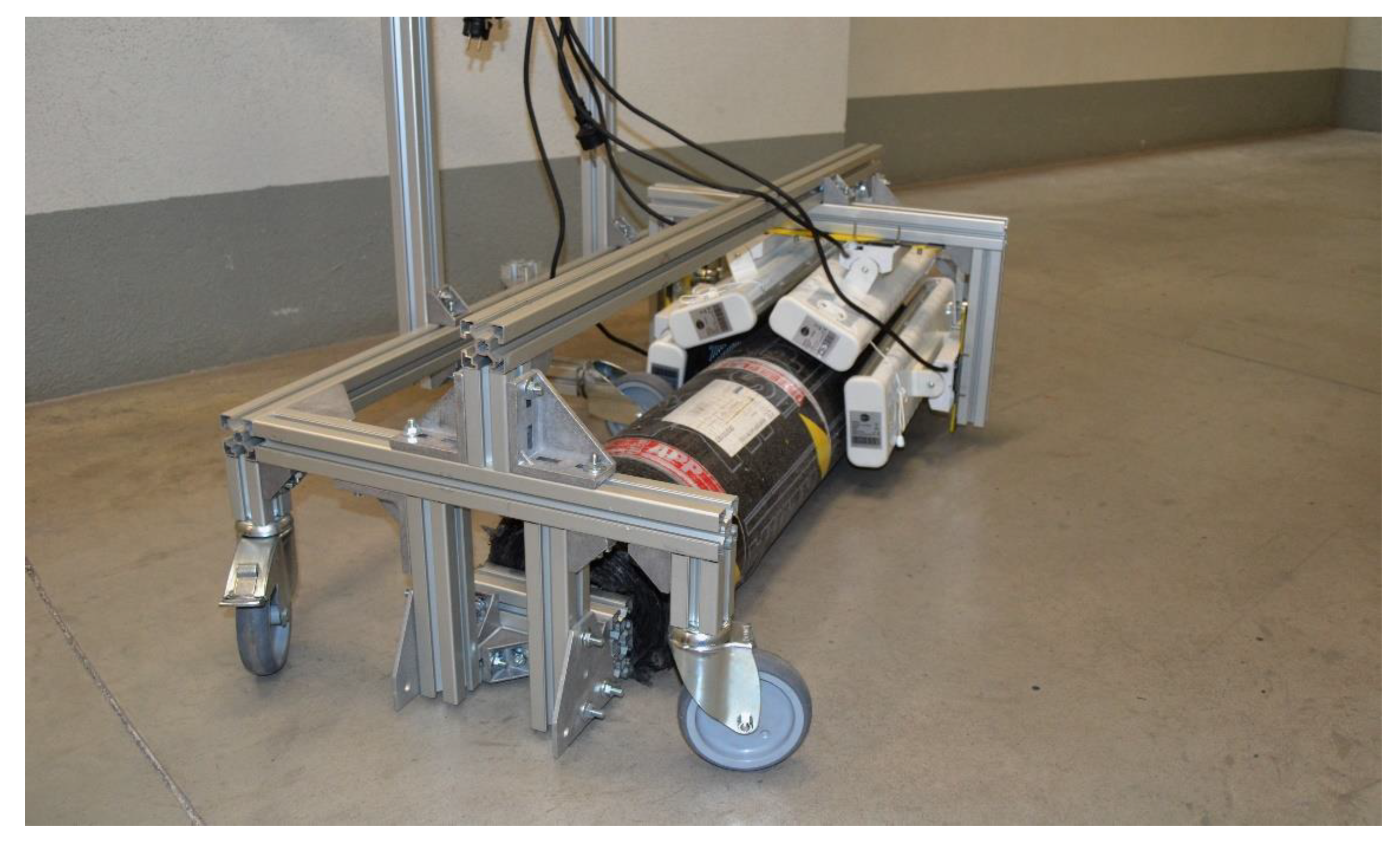
The present equipment refers to a lightweight trolley mechanism that facilitates the installation of asphalt rolls. The equipment is composed of the following elements: a light trolley structure, four wheels for supporting the trolley, an auxiliary wheel for unrolling, a system of infrared heaters, a top enclosure cover to avoid heat loss, small drum rollers for compaction of the asphalt in the overlaps, and general electrical regulators and switches.
2.1. Mechanical Design and Analysis
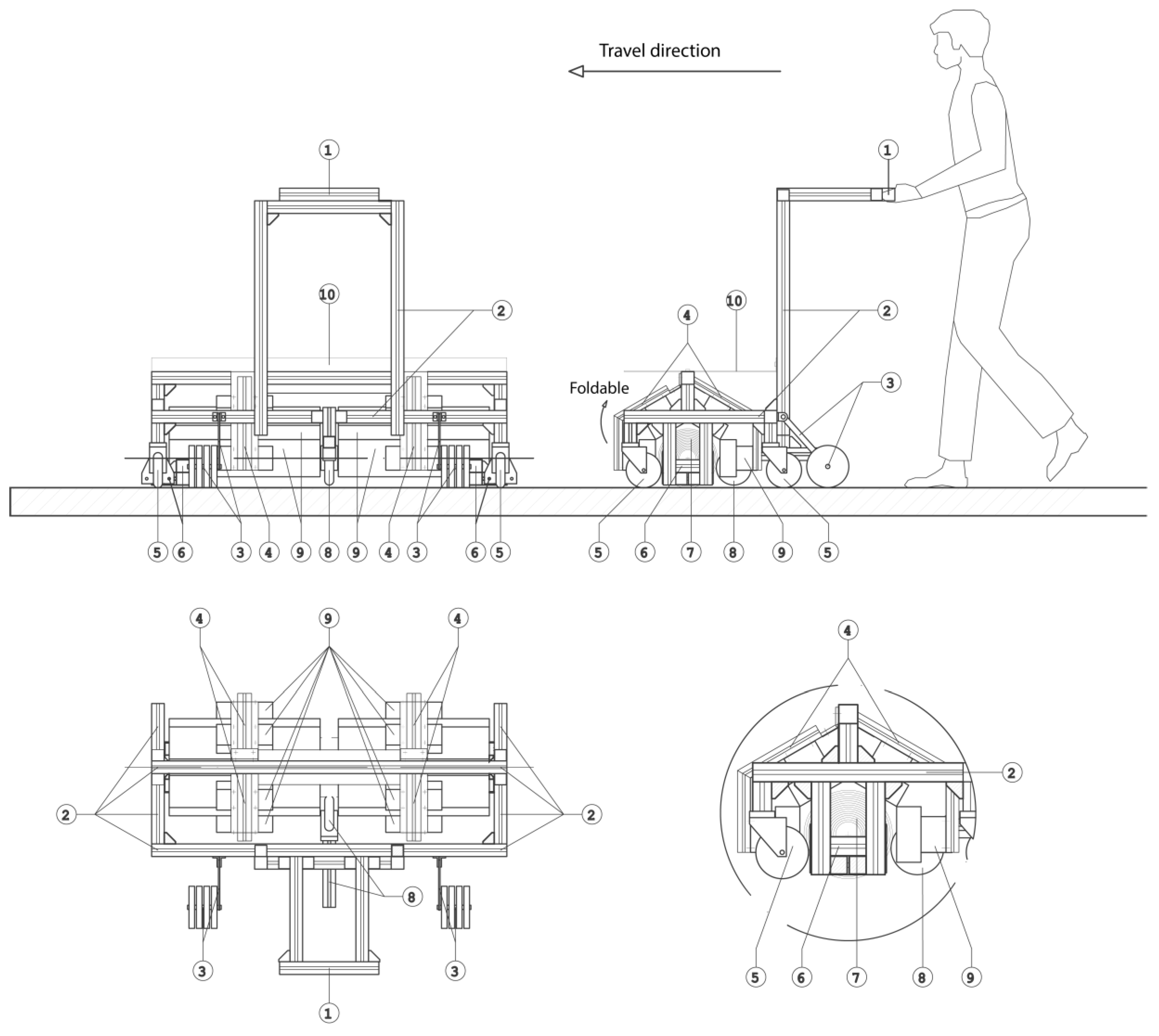
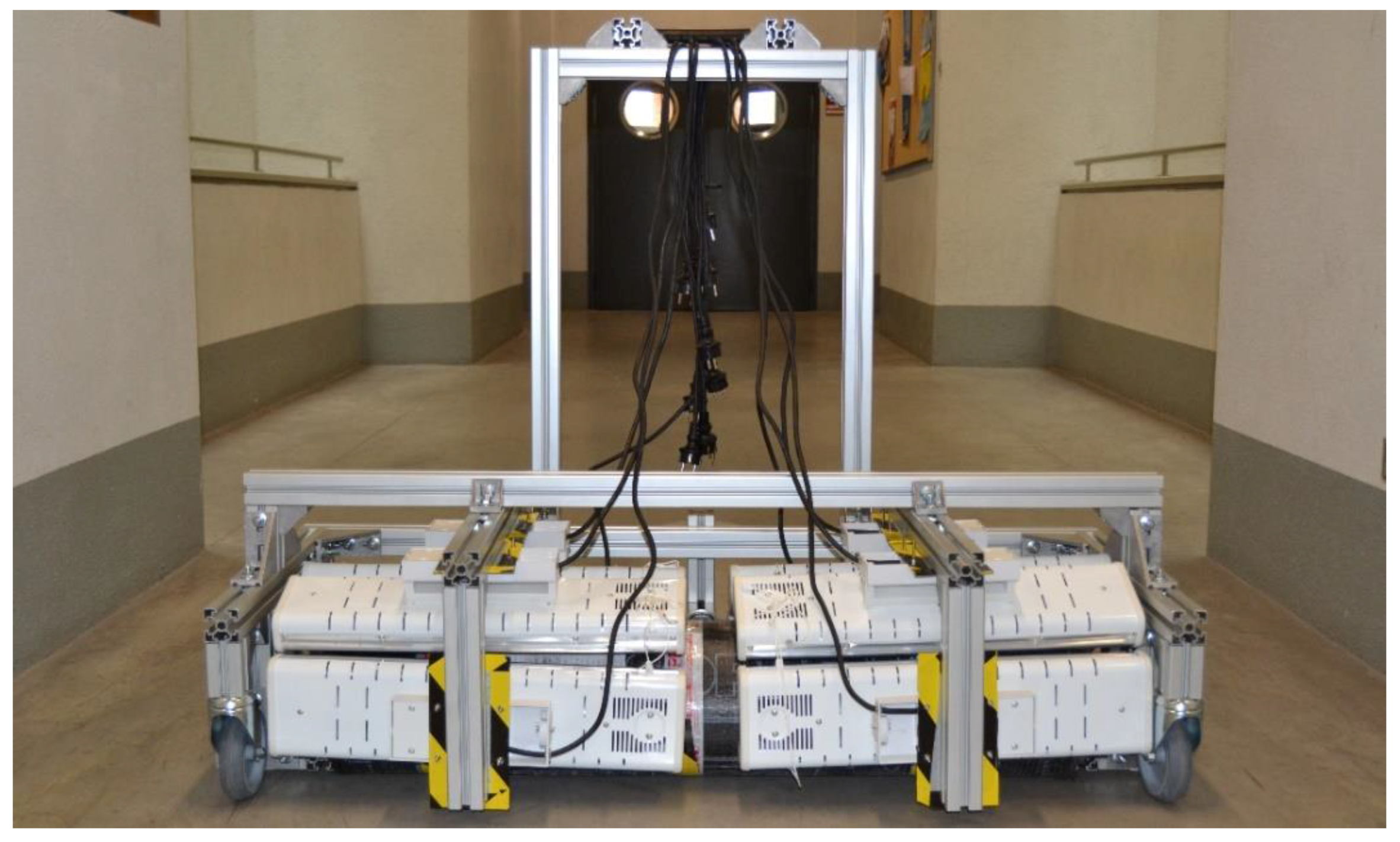
Figure 1 shows three orthogonal views of the equipment design presented in this work. As shown in the right-side view, the trolley (2) can be pushed forwards from the handles (1) located at an ergonomic height for the operator. Four wheels (5) permit the movement of the mechanism. The rear wheels are locked while the front wheels are free to steer to adjust the path of the trolley. The asphalt roll (7) is located inside the structures. The trolley has two locating stops (6) on both sides of the roll that keep the roll in position and allow for the re-directing of the roll while it is unrolling. In addition, the trolley has an auxiliary wheel (8), located in the center of the trolley and at a height lower than the radius of the roll, in such a way that it serves to transmit the pushing force to the roll. The horizontal pushing force is transformed into the roll’s rotational movement, facilitating its unwinding. Also, the trolley includes a pair of small drum rollers (3) for compaction of the asphalt in the overlapping areas.
Finally, this view also shows a system of eight infrared heaters (9) supported by a structure (4) connected to the main frame of the trolley. The heaters are arranged radially and longitudinally around the roll in order to apply the heat in a uniform, progressive, and continuous manner. The enclosure cover (10), preferably made of metal or a ceramic material, is also shown. This enclosure is removable.
Figure 1 also shows the front and top view of the equipment and a detailed view of the heaters’ distribution.
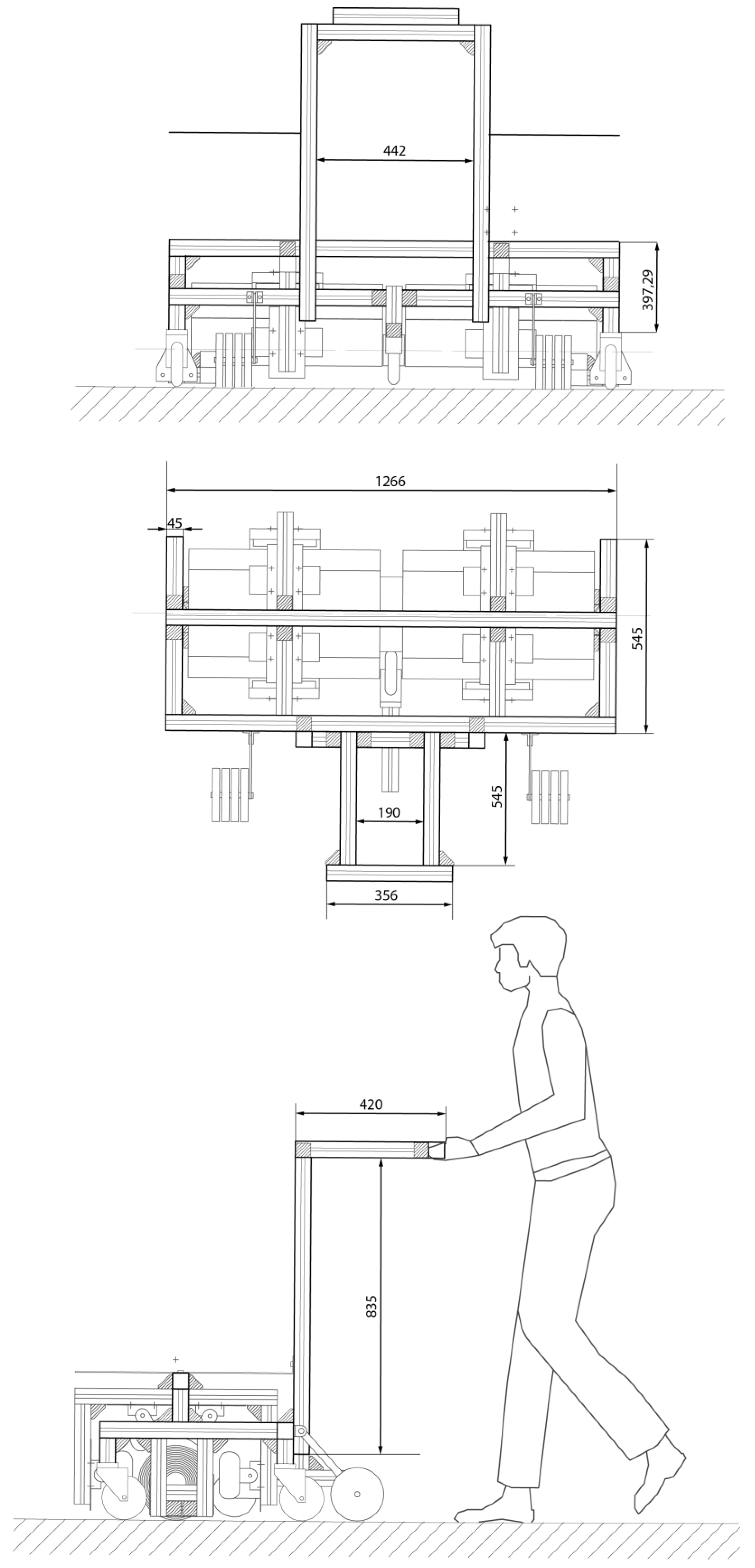
The equipment has been specifically designed for one-meter wide and 10-m-long asphalt rolls. The general dimensions of the design are shown in
Figure 2. Smaller types of rolls can also be compatible with the equipment, but it would require some modifications in the locating stops, though the stops can easily be moved closer to the center of the structure. The same concept could be used for larger rolls, but in this case, modifications to the whole structure would be necessary, as well as a redesign of the heating system. Finally, it is important to indicate that the operator has the ability to adjust the enclosure that controls the heat losses while unrolling. This allows the operator to take advantage of all the heat provided and to reduce electricity consumption.
When using this equipment, it is not necessary to lift the roll since the trolley is directly coupled with it. As the roll is directly supported on the ground, the addition of rollers for support and unrolling is avoided, which lightens the assembly and prevents injuries. The height of the handle is adjustable, and therefore, inappropriate or forced postures and movements can be avoided. In order to control the heat, a general electric regulator and multiple regulators are installed to individually control the heat of the different heating elements. The heaters arranged in the front part can be connected to the frame of the trolley through a folding hinge-type element to facilitate the loading of new rolls.
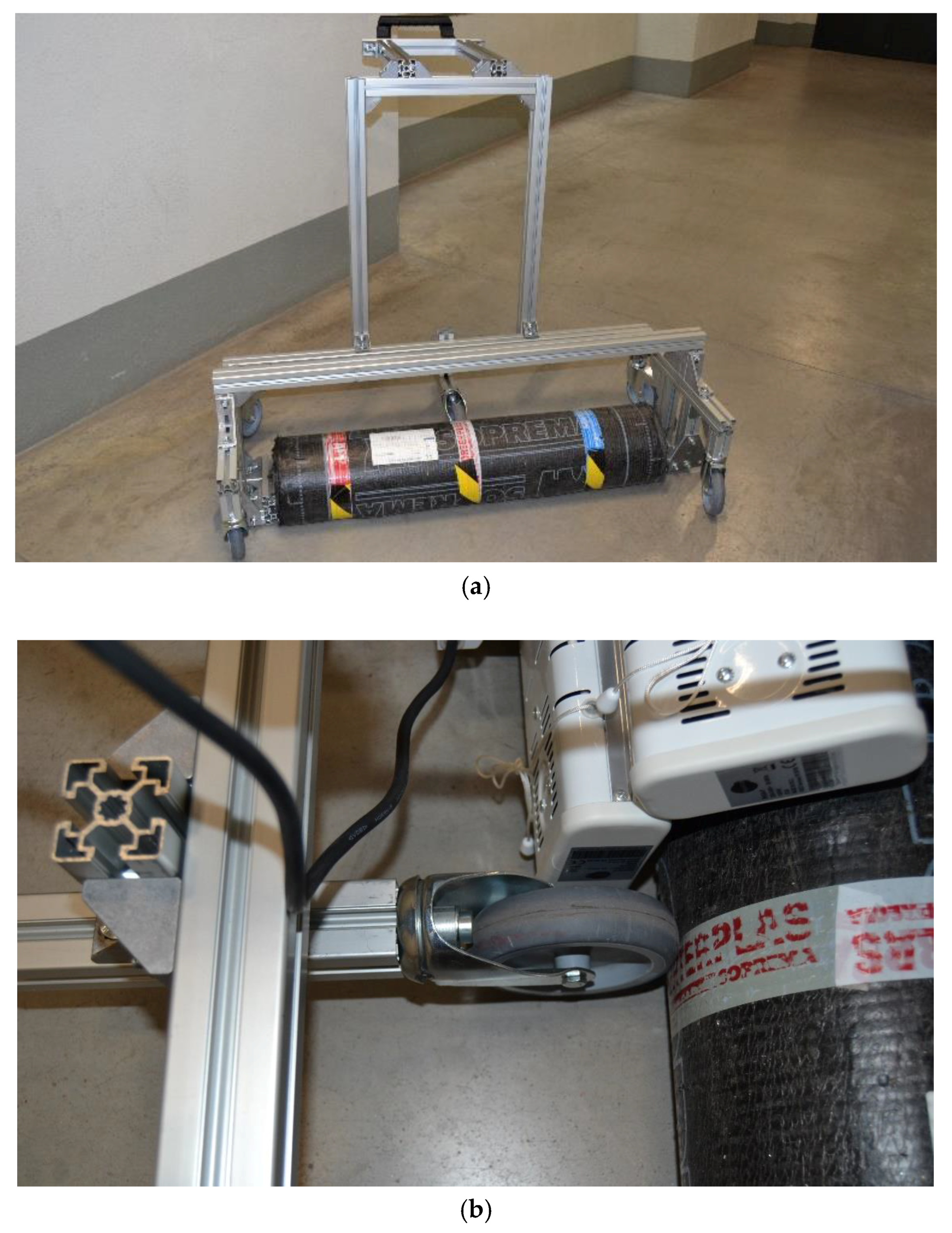
The performance of the auxiliary wheel for unrolling was analyzed in detail. The 3 kg/m2 asphalt rolls were 30 kg in weight and 0.25 m in diameter, and the friction coefficient between the asphalt and concrete, or similar, was estimated to be µ = 0.4. This will lead to a maximum friction force of F = µmg = 117.6 N, i.e., around 12 kg of horizontal thrust force. Such a value is achievable for a construction worker. Thus, if the trolley simply pushes the roll, the worker could displace the roll without unrolling it. This point is especially problematic at the beginning of the installation since there is no adherence between asphalt and floor at this stage. Therefore, there must be an auxiliary system to facilitate the unrolling. The use of an auxiliary wheel permits the conversion of the horizontal thrust into a tangent force, enabling the unrolling of the asphalt roll. The height position of the auxiliary wheel is not a determinant when considering the ideal case of a cylindrical roll.
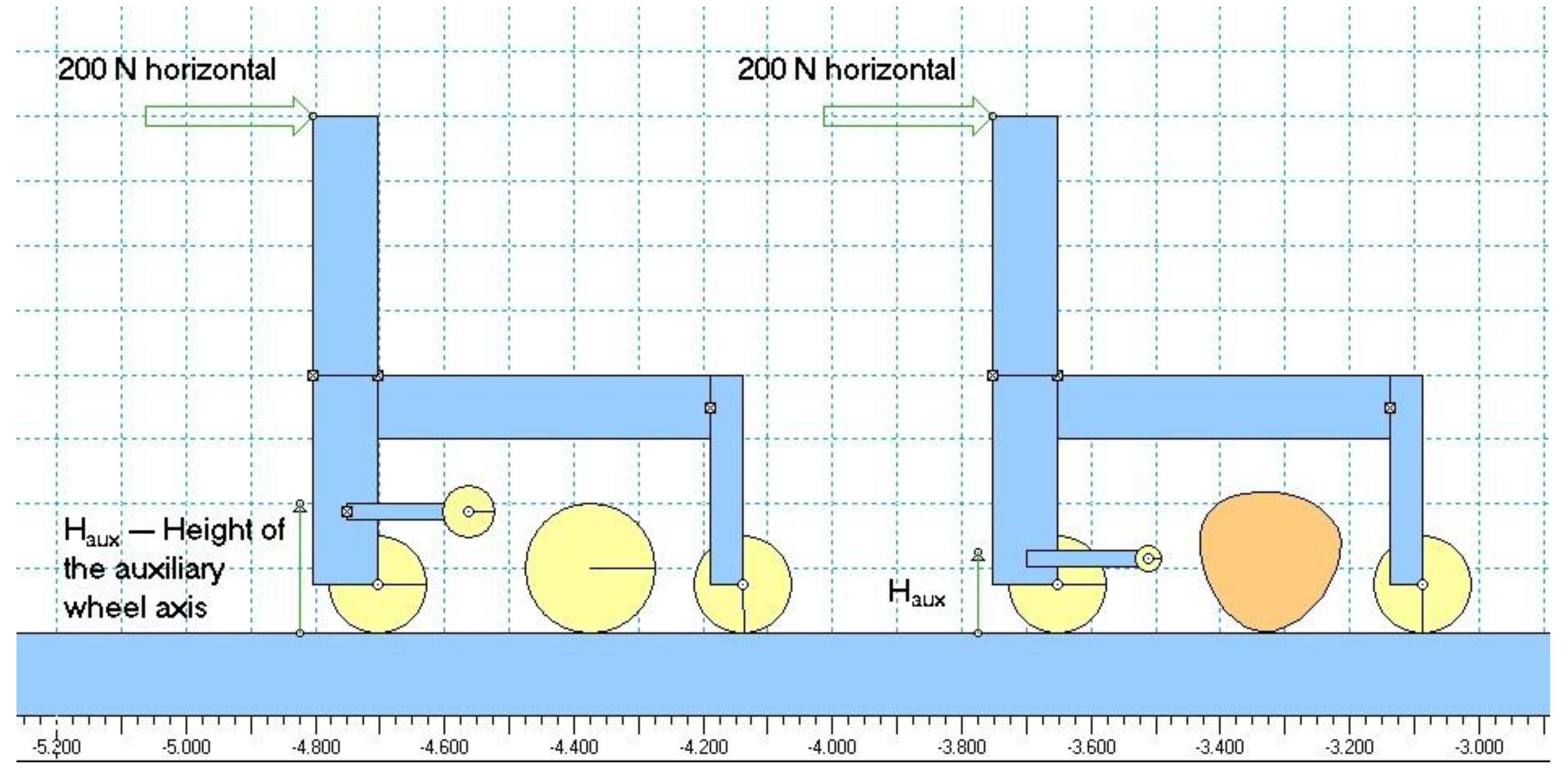
However, there is an additional complication in the unrolling of the rolls because the asphalt rolls are made of a flexible material. The center of gravity of the roll may not coincide with the axis of rotation. A multibody simulation was performed (see
Figure 3) in order to determine the correct location of the auxiliary wheel.
The dynamic model of the trolley is presented in
Figure 3. The model was a 2D plain model including a pair of wheels, the main structure profiles, the asphalt roll, and the auxiliary wheel. The rotational acceleration simulation of the roll was performed for different H
aux positions, i.e., height of the auxiliary wheel from the floor, for different auxiliary wheel diameters and for two shapes of asphalt roll: a perfect circular one and a deformed one. A horizontal thrust of 10 N was considered at the handle position. Pivots and contacts were also implemented assuming the corresponding friction coefficients.
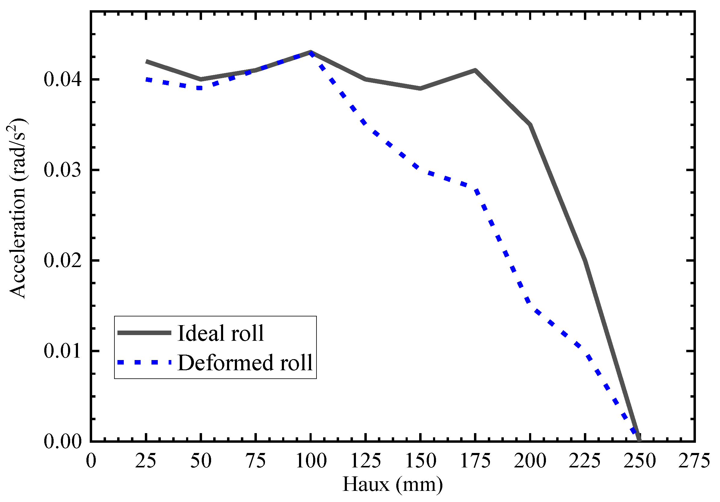
The stationary rotational acceleration of the roll was retrieved after each simulation. This magnitude represents the quality and smoothness of the movement, since a larger rotational acceleration represents a more comfortable unrolling. The analysis of the rotational acceleration with respect to the height and diameter of the auxiliary wheel provides the correct position for the auxiliary wheel. Results of this simulation are shown in
Figure 4.
The angular acceleration of the roll was almost constant if the auxiliary wheel position was below the center of gravity of the roll. If the auxiliary wheel was above this, the pushing force lifted the trolley from the ground at the same time that it accelerated the roll. However, this lifting cannot be allowed, thus the correct position of the wheel is lower than the center of gravity of the roll. Commons rolls with a 125 mm nominal radius may be deformed, and their center of gravity can be even lower than the nominal radius; therefore, we set 90 mm as an adequate height for the auxiliary wheel. The main concern in using an auxiliary wheel is that it has to be in constant contact with the roll, and hence there is a middle strip in the roll that cannot be completely heated. Otherwise, asphalt will be adhered to the wheel and will lock it. However, this part is less critical since the lateral overlaps are the areas that must really seal the roof between rolls. In any case, this middle strip will be partially adhered due to residual heat.
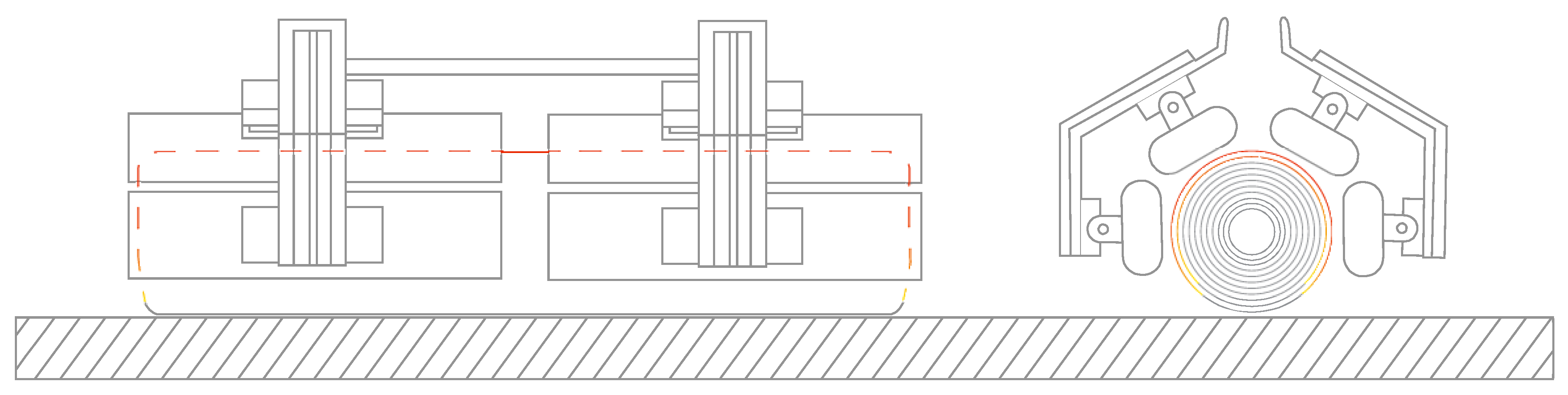
In the proposed equipment, eight heaters are arranged in a structure forming the upper part of a hexagon, as shown in
Figure 5. In this way, adding up the surface of the eight heaters, the total surface of the roll affected by heat radiation is 65% of the roll circumference. The total surface affected by the eight infrared heaters is 0.6 m
2 (this is the surface that will be heated, excluding the aforementioned auxiliary wheel middle strip).
The selected infrared heaters are quartz resistance heaters with 1200 W of nominal continuous heat power each. Each heater contains two quartz lamp resistances. Each resistance can reach up to 660 °C on the surface under natural convection conditions according to the lamp manufacturer. Therefore, the total nominal thermal radiating power is thus 9600 W applied to 0.60 m2. As quartz lamps have an efficiency of around 86%, the roll receives a heat flux of 11,794 W/m2.
The installation procedure starts by distributing the rolls along the roof with a separation distance approximately equal to the length of the rolls. They shall be placed in parallel, and the heaters have to be turned on so they can warm up until they reach their operational temperature. Warming up time is estimated to be around 5 min, while the roll distribution depends on the extension of the surface. In general, one hour for roll distribution and warming up should be enough. Then, installation begins by locating the first roll between the heaters of the trolley. This can be done simply by tilting and pushing the trolley. The worker has to wait for a certain time in order to heat the first layer of the asphalt enough to be adhered to the ground. This minimum waiting time was set to 32.5 s, as shown in next sub-section. Then, the worker must push the trolley, and the roll is adhered to the ground. The unrolling time was estimated at 2.5 s. The unrolling length was approximately equal to a single step of the worker. The calculation of the minimum heating time is detailed in the next thermal design
Section 2.2.
Therefore, if the installation of 0.60 m
2 can be done in 35 s, the actual average installation speed is approximately 1 m/min. Thus, considering eight hours of labour a day, spending one hour on roll distribution and breaks, the total installation capacity using this equipment would be 400–420 m
2 per person a day. This is more than manual installation, in which a common rate is 190–200 m
2 [
13]; this benefit comes along with the associated advantages of reduced effort and the non-use of fuels.
2.2. Thermal Design and Analysis
One of the main problems in manual installation is that the use of torches results in a heat flux that is only applied to one localized area. This means that heat must be applied very carefully as the asphalt undergoes a temperature increase from ambient temperature, minimizing the installation performance. This localized heat income is, in most cases, much larger than that needed for a proper asphalt installation since workers do not have any measurement or control of the temperature beyond their own eyesight estimations. In addition, the energetic efficiency of the torches is very low because most of the heat is lost due to air convection. In order to optimize the whole process, it will be useful to determine exactly the amount of heat that needs to be transferred to the roll for a proper adhesion to the ground.
We determined a temperature criterion for a correct roofing asphalt installation. This criterion was based on the viscosity behavior of asphalt with temperature. Asphalt viscosity decreases asymptotically with the increase of the temperature [
14]. From a value of 140 °C, the viscosity was lower than 125 mPa·s, which is very close to its asymptotic value. As the asphalt’s bonding with the ground was based on its viscosity, 140 °C could be considered as a hot-enough operation point where the asphalt can be correctly bonded. Other physical properties of asphalt are listed in
Table 1 [
15].
Thus, in the first approach, the total power needed to heat up one meter squared of a 3 kg/m
2 asphalt roll in 1 min could be calculated as the power necessary to heat the complete mass to 140 °C from an initial temperature of 22 °C, which was:
This value is not far from the nominal thermal power available from the heaters. In any case, the actual environmental temperatures that are found in workplaces can vary from 4 to 40 °C. For these extreme conditions, the calculation also varies, needing more power when the ambient temperature is lower and less power when the ambient temperature is higher. The equipment has been designed for application at temperatures around 22 °C.
This initial power calculation is not accurate since the roll is formed of several consecutive layers of asphalt. Therefore, the heat applied to the roll is used to heat up the whole roll and not only a single layer, leading to a temperature gradient along the radius of the roll. This temperature gradient helps to pre-warm subsequent layers so they can be heated up faster, but it can also lead to adhesion between layers. In addition, a natural convection heat transfer also reduces the net heat transfer rate. A more detailed analysis was carried out by means of a finite element method transient thermal model in order to determine the exact temperature profile along the roll radius with respect to time.
The thermal transient FEM analysis was performed using ANSYS Structural software 2019 R2 (ANSYS, Inc; Canonsburg; PA, U.S.A.). FEM thermal simulation objectives are to determine the temperature profile behavior with respect to time for the radiation applied and to select the proper heating time to have the first layer ready to be installed, and so on for subsequent layers.
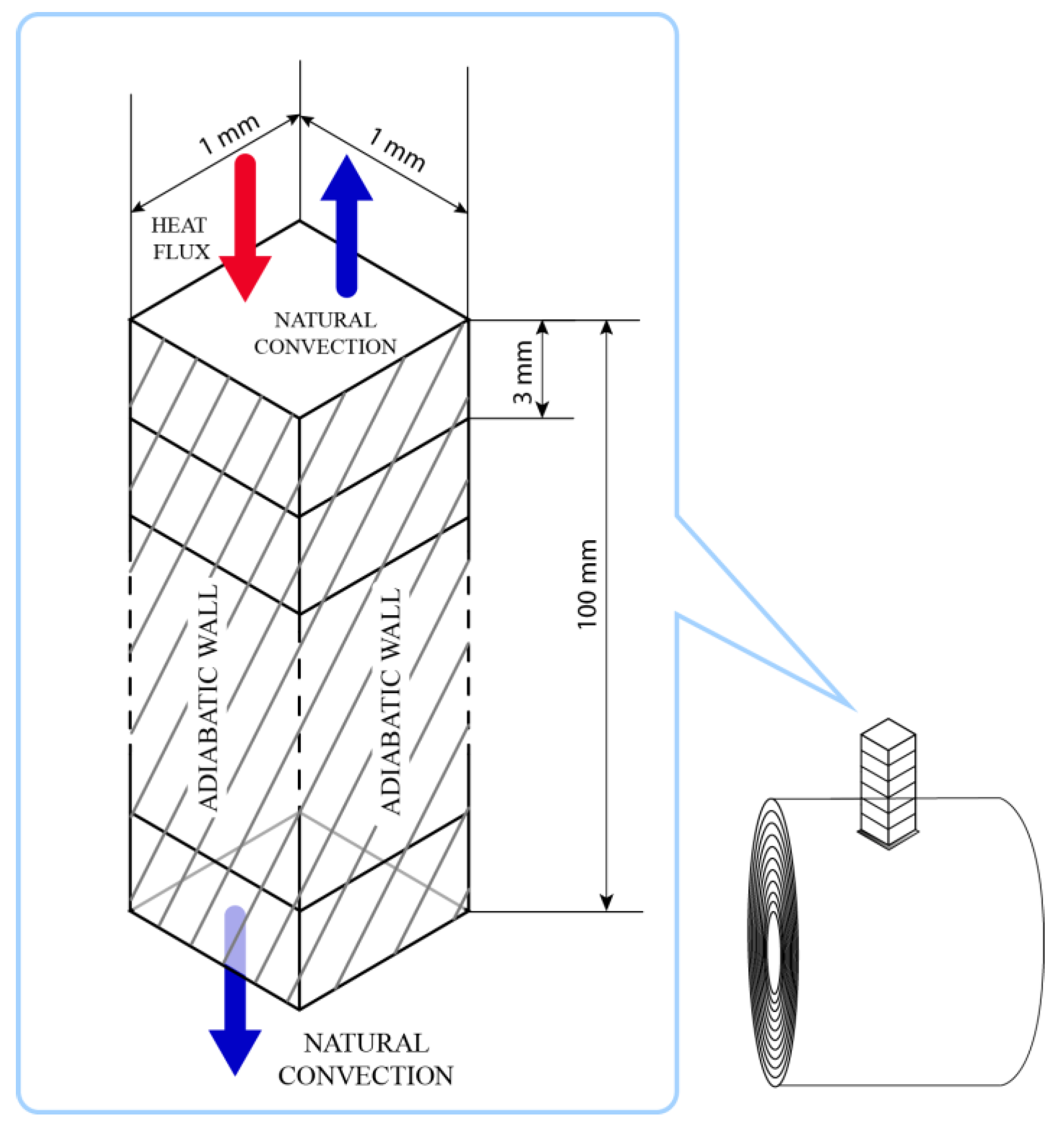
We considered just a small slice of the roll in order to simplify the model. The simulation model geometry is a long prismatic shape with a 1 × 1-mm cross-section and a length equal to the radius of the roll, which in this case was 100 mm. The maximum element size was set to 0.25 mm, leading to a mesh of 6400 elements.
Asphalt material was created using the properties listed in
Table 1. Different boundary conditions and thermal loads were applied. Free natural air convection was imposed at the top and bottom surfaces with a convective heat transfer coefficient value of 20 W/m
2∙K (we selected this value as an arbitrary value within the normal range 10–100 W/m
2∙K [
16]) and an external temperature of 22 °C. The lateral walls were considered adiabatic because of the symmetry of the geometry. On the top surface (radiated surface), a heat flux was inserted. The value of this heat flux was 11,794 W/m
2 according to the available full heat capacity provided by the chosen infrared heaters. Schematics of the FEM model conditions are depicted in
Figure 6.
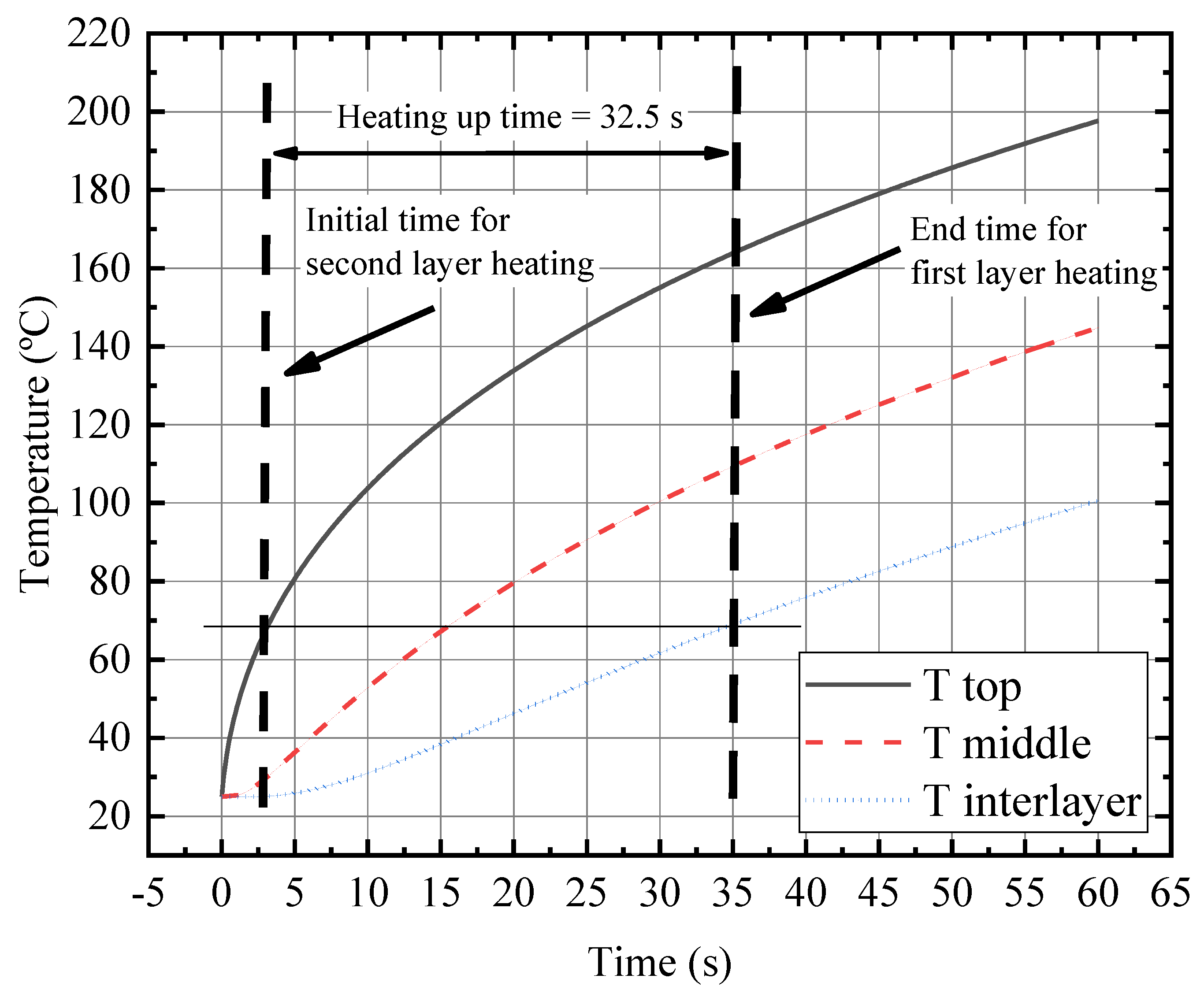
A transient thermal simulation was run from 0 to 60 s, and temperatures were calculated at different key points: the top of the surface (z = 0 mm), the middle section of the first layer (z = 1.5 mm), and the interlayer point (z = 3 mm). Temperatures with respect to time are presented in
Figure 7.
In order to determine the proper heating-up time for installing the first layer, we defined the temperature profile criteria. The temperature profile along the layer must be high enough to bring the majority of the asphalt close to the asymptotic viscosity behavior point (140 °C). In contrast, the temperature at the interlayer point must be low enough to prevent adhesion between layers. Therefore, our criteria were that the top surface temperature must be well above 140 °C, the middle section temperature must reach at least 110 °C, and the interlayer point must be lower than 70 °C. At t = 35 s, the previous criteria were fulfilled. Therefore, the worker had to wait 32.5 s to install the first layer. Complete temperature profiles for t = 35 s are shown in
Figure 7.
The heating up time to install the second and subsequent layers can be also retrieved from the previous simulation results. After the first layer’s heating-up time, the first–second interlayer temperature was 69.18 °C. Thus, the heating up time for the second layer was be slightly shorter since the layer was already pre-heated. From
Figure 7, we determined that at time t = 2.5 s, the top surface was already at 69 °C, the same temperature as the interlayer at the end of the first layer’s heating-up time. Therefore, it was necessary to wait 32.5 s to bring a new layer’s top temperature from 69 °C to 169 °C and to again obtain the same temperature profile that satisfied the installation temperature profile criteria. Thus, this can also be applied to subsequent layers.
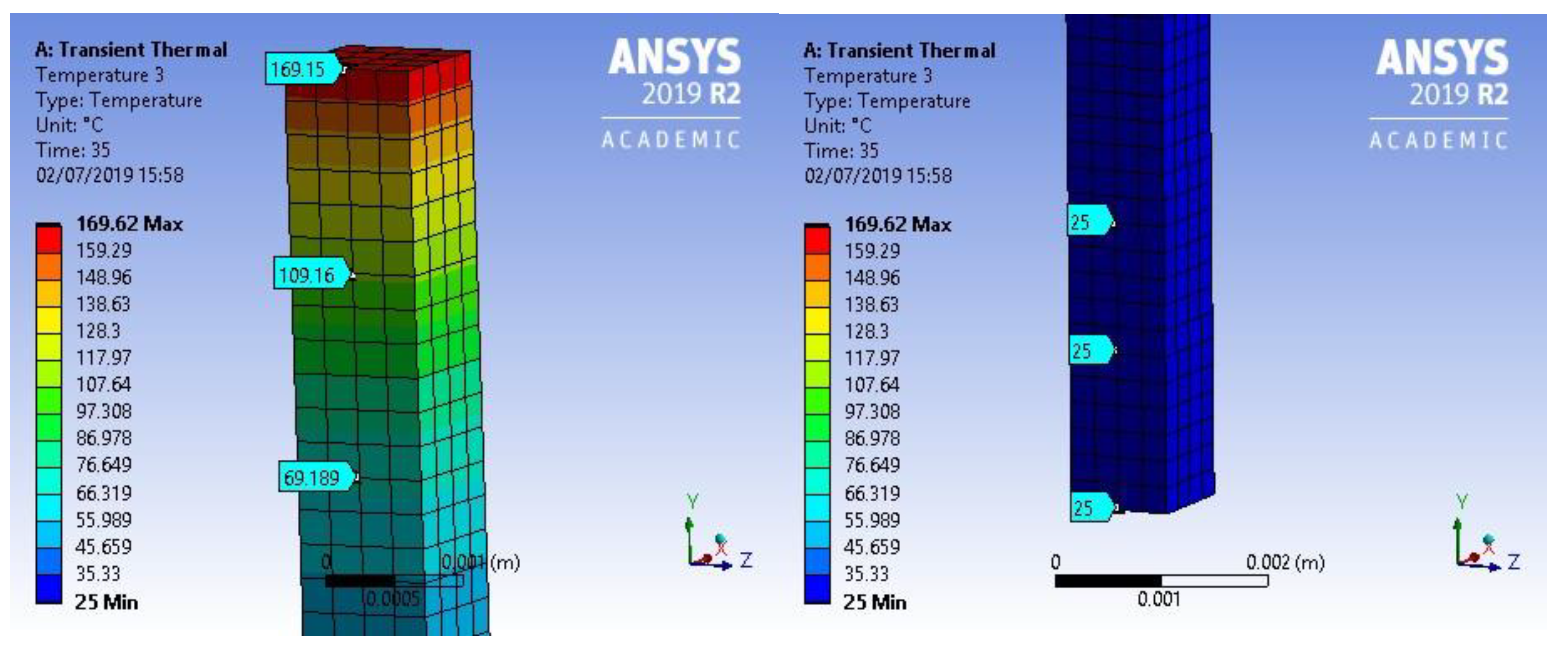
Therefore, we concluded that the heating-up time for a layer will always be lower than 35 s for 0.6 m
2, except for the first one, which numerically demonstrated the claimed average installation speed. The temperature profile at 35 s of the small slice of the roll is shown in
Figure 8.
4. Test Results and Discussion
The test campaign was planned and executed in order to validate the assumptions considered during the design phase. The objectives of the test were to determine the top surface temperature that permitted a good adhesion of the asphalt roll, to determine the temperature that prevented adhesion between the layers, to determine what the temperature of the roll was after the designed heating-up time, and to test the equipment in outdoor installations with asphalt roofing rolls.
4.1. Preliminary Temperature Test
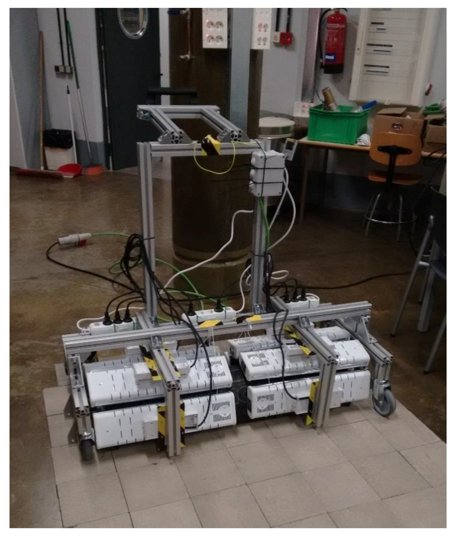
A preliminary temperature test was done to validate the temperature criteria selected during thermal design. For this test, one of the sub-frames containing four infrared heaters was placed above a sheet of asphalt roll just to heat it up (
Figure 13). Then, heaters were activated and the sample of asphalt was heated.
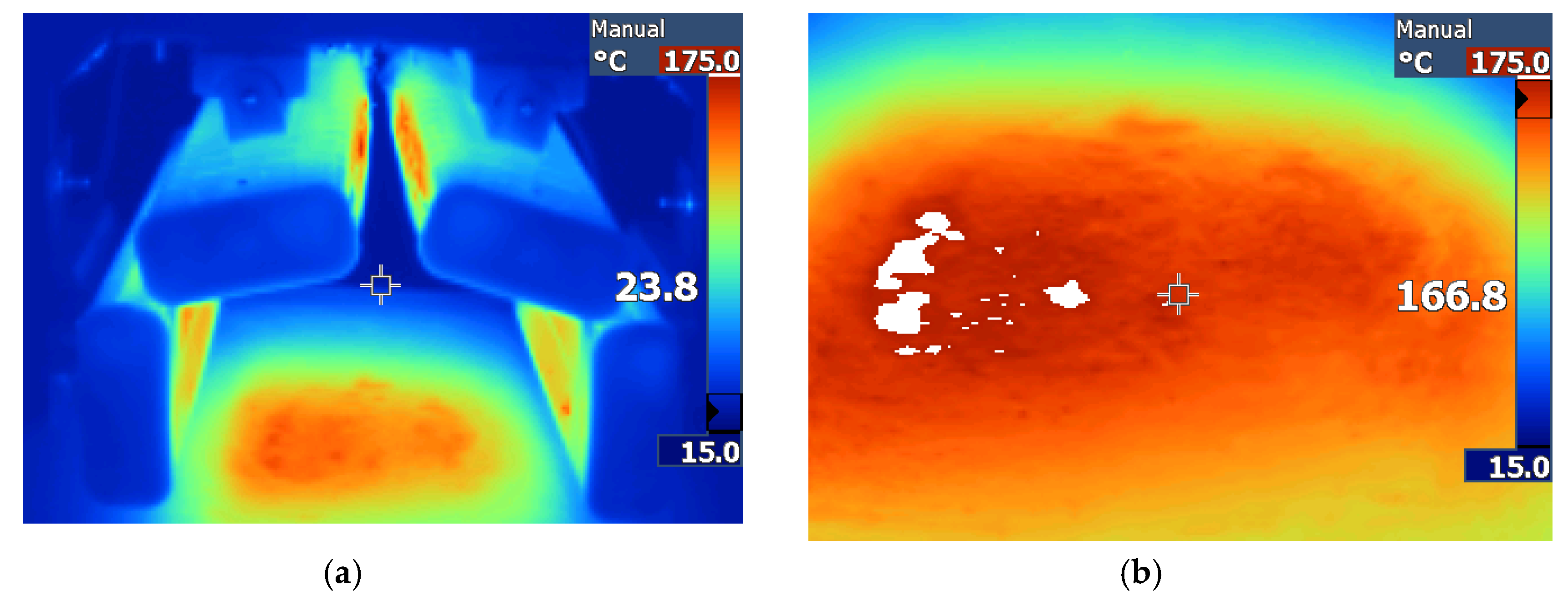
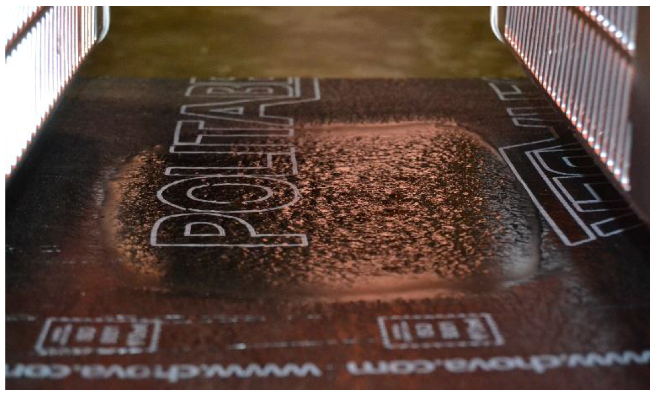
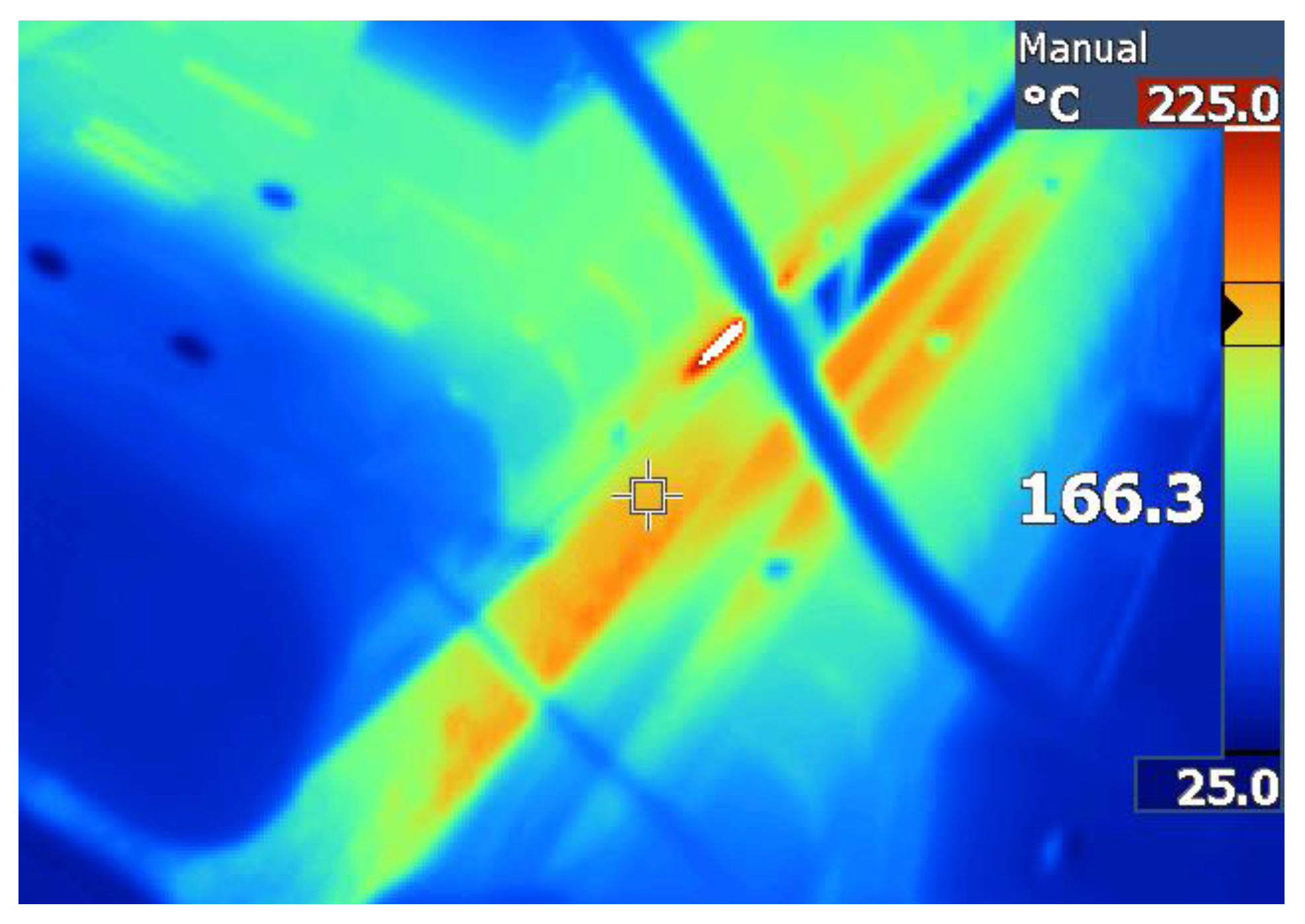
After one minute of heating, the sample of asphalt roll was brought up to 166.8 °C (
Figure 14). At this temperature, the asphalt was already very viscous and most of the protective thin film had already been removed. There were even some boil-off bubbles coming from the outgassing of the asphalt mass (
Figure 15). This piece was adhered to the surface below very easily. Therefore, we concluded that if the top surface is at least 166.8 °C, the asphalt roll can be properly installed. This partially validated the temperature profile criteria that we supposed in
Section 2.
4.2. Interlayer Adhesion Test
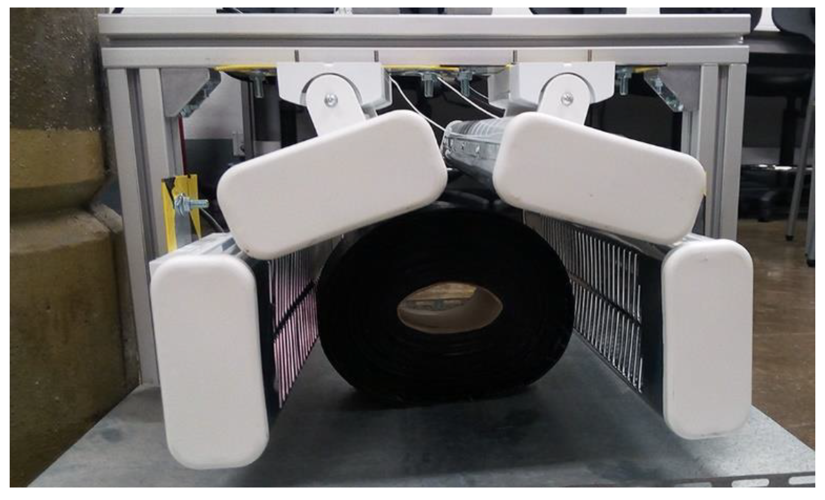
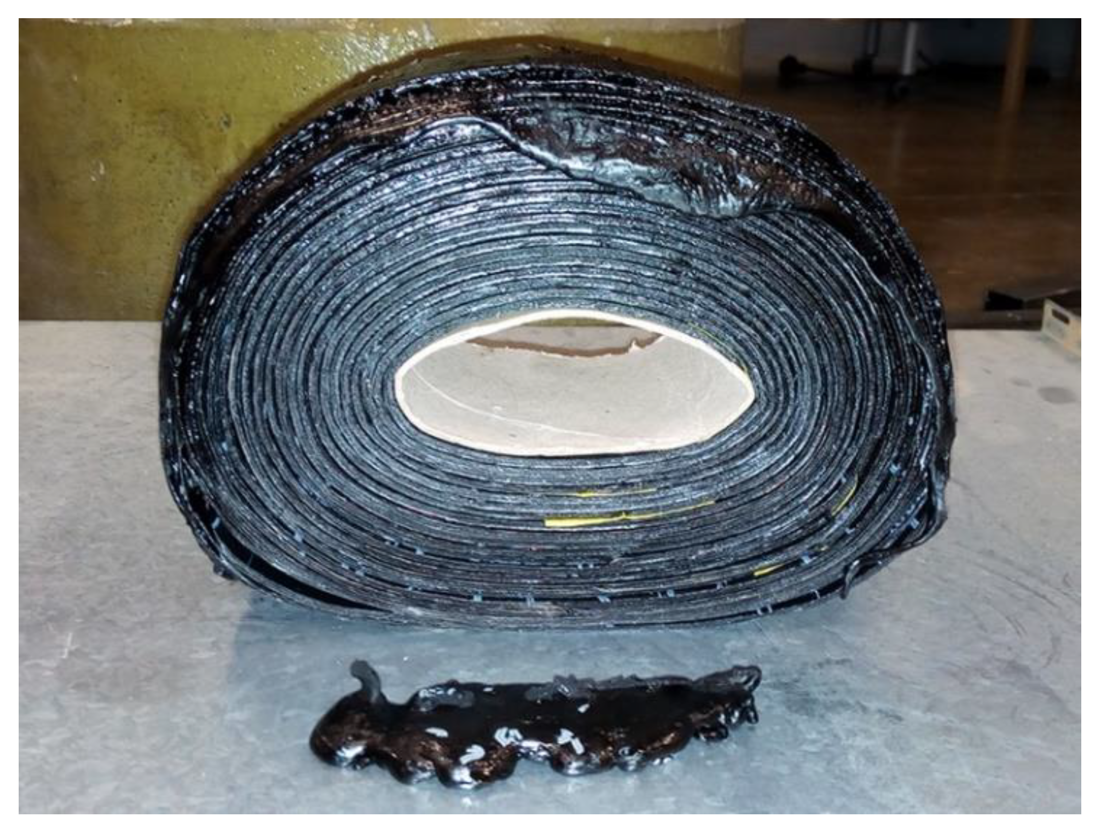
The objective of the second test was to determine the temperature beyond which the layers adhere between themselves in the roll. For this test, a slice of the cylindrical roll was cut and located on a metal sheet surrounded by four infrared heaters (
Figure 16).
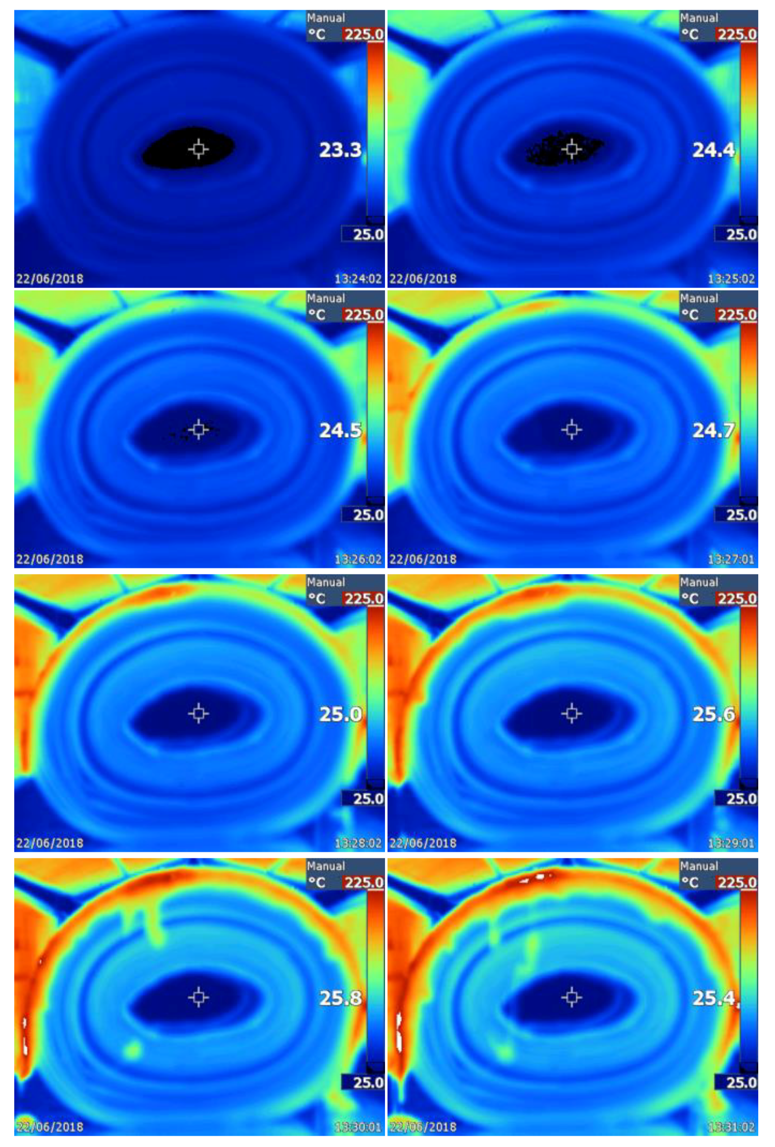
Then, the four heaters were activated, and the temperature variation of the roll was registered by using thermal imaging. Each image included the time at which it was taken. Different images taken at different times are shown in
Figure 17.
Since the infrared heaters were completely off, they needed almost 3 min to achieve their maximum heating power capacity. After 8 min of continuous radiation, the roll was hot and some of the outer layers had adhered together (
Figure 18). After the test, we tried to separate the layers, and we determined that seven layers were merged together. These seven layers corresponded with the limit temperature indicated in clear green/blue in the last picture in
Figure 17. This color corresponds to a temperature between 60 and 80 °C. Therefore, we concluded that below 60–80 °C, layers do not adhere together but above these temperatures they do. Again, this validated some of the temperature profile assumptions made in
Section 2.
4.3. Indoor Heating-Up Time Test
Once the temperature profile criteria were validated, we started to test the installation of rolls. The first test was carried out to determine the proper step-by-step planned installation method.
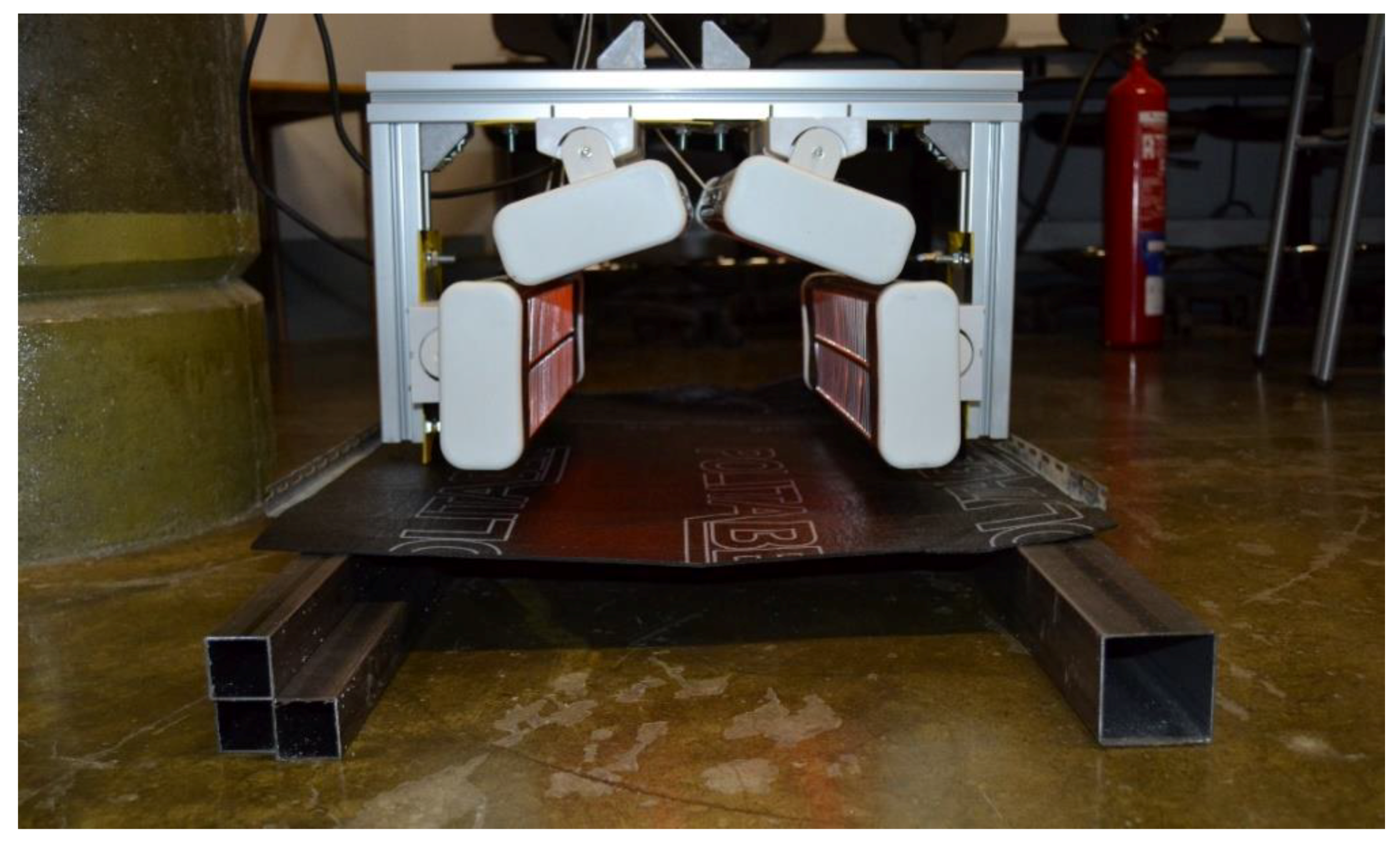
For this, a test ground area made of floor tiles was constructed in the laboratory. Then, the roll was placed above, and with the equipment, we started heating the roll (
Figure 19). When the top surface temperature reached almost 170 °C (
Figure 20) after 35 s, an installation step-ahead was done (installing 0.6 m
2 per step). The uniformity of the radiated surface was admissible and the adhesion between roll and ground was satisfactory. This permitted the validation of the heating and waiting times determined in
Section 2.2.
However, during this test, we realized that the unrolling precision was not so high. The mass unbalancing of the roll generated an excessive unrolling, leading to a poor installation of some areas. This was corrected by approaching the lateral stops, giving less freedom to the roll to freely unroll. Another issue came from a poor adherence of the last 1–2 cm at the lateral limits. This was due to the borders of the infrared heaters, which did not surpass the roll. In order to correct this, the heaters can be located more laterally, widely covering the roll limits.
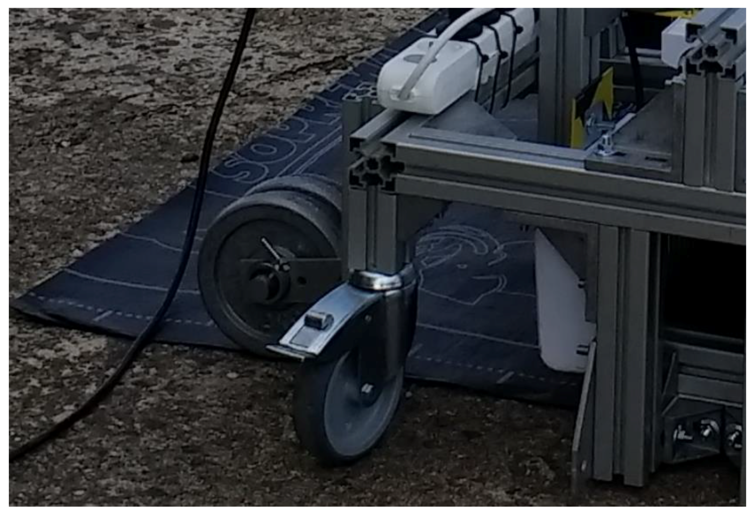
4.4. Outdoor Installation Test
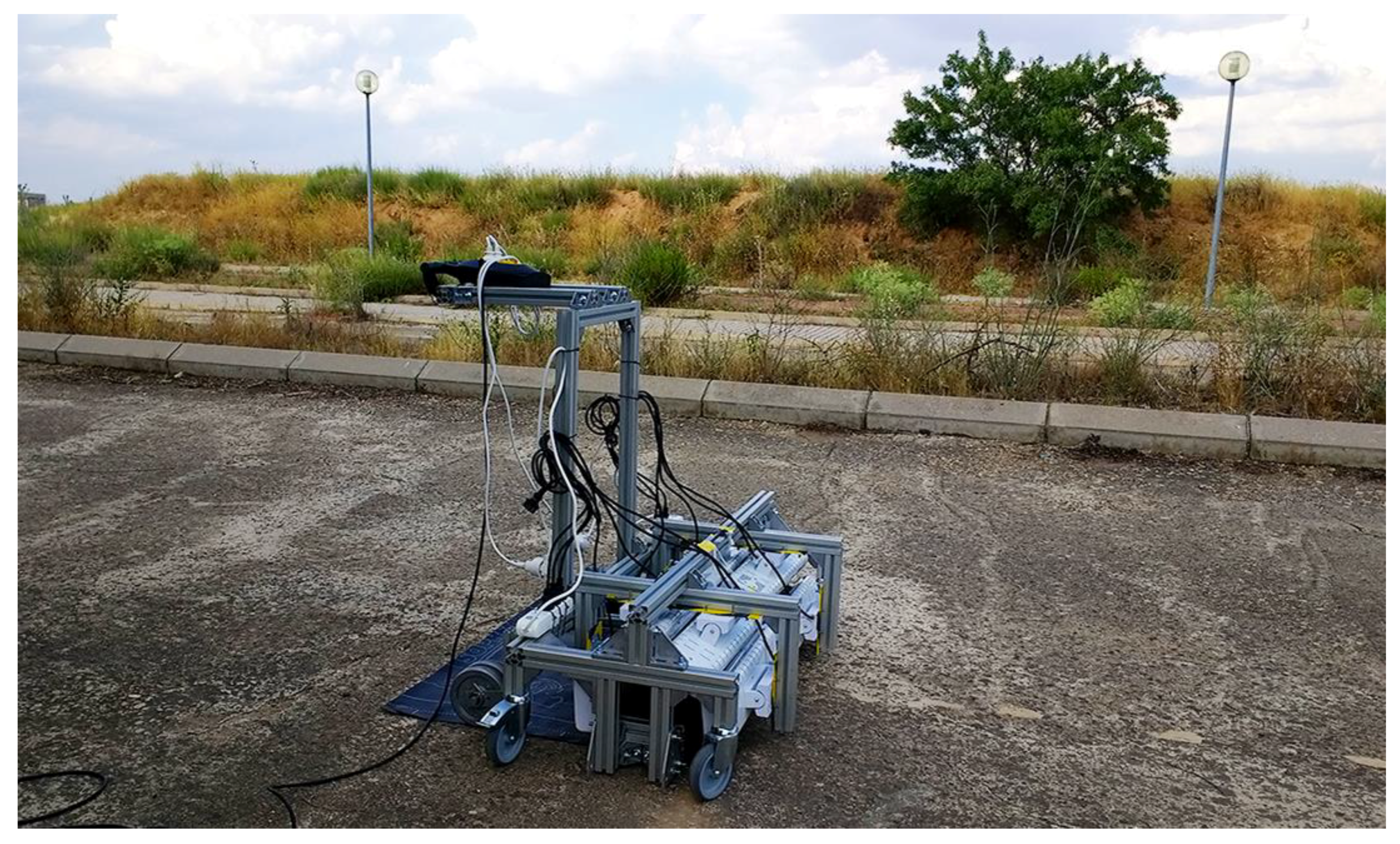
Finally, the equipment was tested in an outdoor facility in order to demonstrate its installation capacity. The equipment was connected to a 14-kW diesel portable generator (
Figure 21).
The equipment was activated, and after 2 min of infrared heater pre-warming, the installation began.
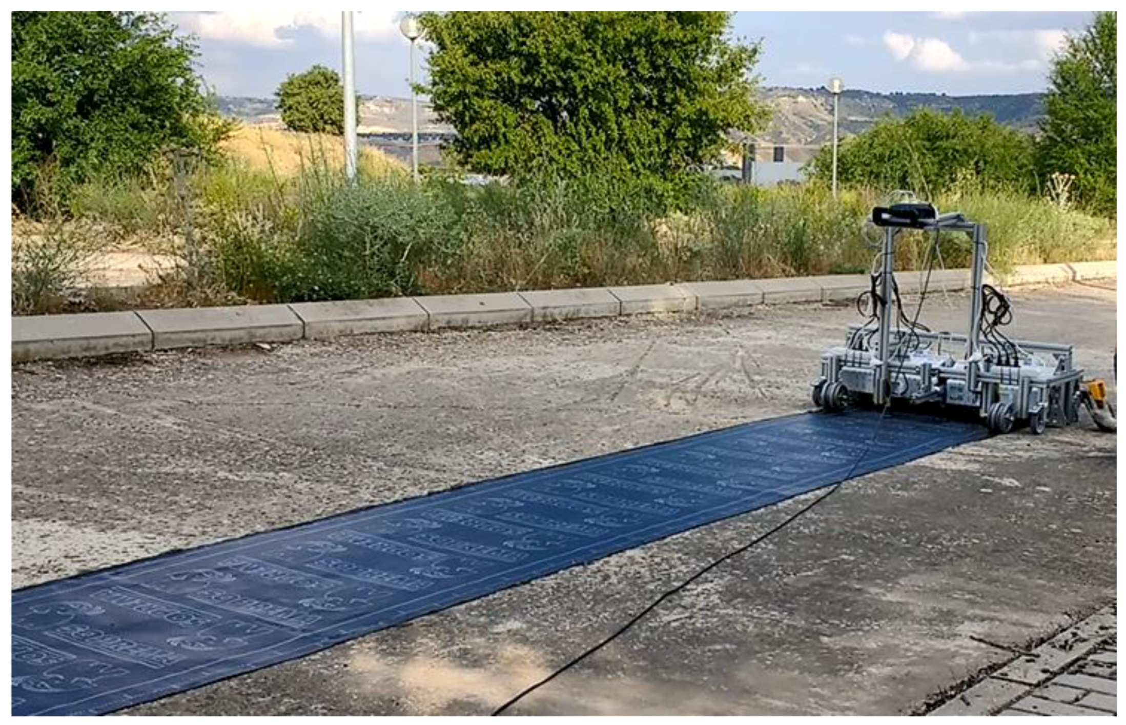
A complete asphalt roll was adhered to the ground by following the step-by-step installation procedure, as shown in
Figure 22. A total of eight meters were adhered after approximately eight minutes of heating up, demonstrating the claimed speed.
However, we identified several issues with the installation and with the equipment itself. As stated previously, it is hard to accurately control the unrolling step, thus there were some asphalt strips that were not heated up. The lateral limits were also not totally adhered because of a lack of extra heat in this area. Moreover, the small pressing drums needed to be heavier in order to effectively crush the overlaps. It would be very convenient to include a chronometer or even a thermal camera that indicates to the worker the exact moment for unrolling. Last but not least, asphalt was also attached to some parts of the trolley such as the lateral stops, which must be prevented to ensure a long lifetime of the equipment.
5. Conclusions
In this article, we presented the design, manufacture, preliminary thermal test, and operation test of a new piece of equipment for mechanizing the asphalt roofing process. The equipment was small and lightweight, and included infrared radiators instead of fuel burners. This provided optimal clean heat transfer to the asphalt rolls. Moreover, the equipment had several advantages with respect to manual installation, such as roofing capacity, cleanness, safety, uniformity, and eco-friendliness.
We analyzed and experimentally validated the temperature criteria for an adequate installation asphalt roll. These criteria were: top outer temperature must reach around 170 °C and the interlayer temperature cannot be higher than 70 °C to prevent interlayer adhesions. With these criteria and with the available heating power, the heating up time to install 0.6 m2 was determined and tested as being 35 s, including the mechanical process of unrolling. This demonstrates an installation speed of 1 m/min, on average, for 3 kg/m2 rolls, which leads to around 400–420 m2 per person a day, more than the usual manual roofing rate.
However, we identified several issues with the installation and with the equipment itself, such as gaps in the adhesion due to inaccurate unrolling and excessive asphalt contamination in some parts of the equipment. The unrolling could be improved by changing the lateral stops or by adding another type of unrolling system. To prevent the adhesion of the asphalt to the equipment, it should be covered by a non-stick coating. Another option could be to move the heaters away from the roll, at the expense of losing some heating power.

 ,
, 


