Parameter Equivalent Method of Stator Anisotropic Material Based on Modal Analysis

1
School of Mechanical Engineering, Tianjin University of Science and Technology, Tianjin 300222, China
2
Automotive Engineering Research Institute of China Automotive Technology and Research Center Co. Ltd., Tianjin 300300, China
3
School of Automotive Engineering, Hubei University of Automotive Technology, Shiyan 442002, China
*
Author to whom correspondence should be addressed.
Energies 2019, 12(22), 4257; https://doi.org/10.3390/en12224257
Submission received: 1 September 2019
/
Revised: 28 October 2019
/
Accepted: 1 November 2019
/
Published: 8 November 2019
(This article belongs to the Special Issue Modeling, Simulation and Control of Electric Drive Systems)
Abstract
:Accurate calculation of the vibration mode and natural frequency of a motor stator is the basis for reducing motor noise and vibration. However, the stator core and winding material parameters are difficult to determine, posing issues which result in modal calculation bias. To address the problem of calibrating the stator material parameters, we developed a parameter correction method based on modal frequency. First, the stator system was simplified to build a stator system finite element model. Secondly, the relationship between modal frequency and material parameters was analyzed by finite element software, the relationship between modal frequency and material parameters was derived, and the anisotropic material parameter correction method was summarized. Finally, a modal experiment was carried out by the hammering method, and the simulation and experimental errors were within 3%, which verified the accuracy of the finite element model. The proposed correction method of anisotropic material can quickly determine the stator material parameters, and the stator core and winding anisotropic material can ensure the accuracy of the modal analysis.
1. Introduction
In recent years, with the continuous development of high-performance materials, the performance of magnetic materials, such as AlNiCo permanent magnets, ferrite permanent magnets, and rare earth permanent magnets, has continued to grow. Permanent magnet motors are increasingly being used in electric vehicles. Compared with electric excitation motors, permanent magnet motors have the advantages of a high torque-to-current ratio, high torque-to-volume ratio, high efficiency, small size, and simple structure. They can not only replace some of the traditional excitation motors but can also achieve a high level of performance that is difficult to obtain with electric excitation motors. Therefore, many industries are interested in such motors [1,2,3,4,5].
Like other types of motors, permanent magnet motors generate vibration and noise during operation. From the perspective of the motor body, the natural frequency of the motor should be considered in order to avoid resonance, and the mechanical strength and other issues related to high-speed permanent magnet motors also need to be considered. The vibration noise generated during operation is still a significant problem in some specific industries and applications, such as in aviation, ships, and automobiles.
Presently, finite element simulation of electromagnetic noise mainly adopts the magnetic field structure–acoustic multiphysical coupling method [6,7,8]. The first step is mainly divided into magnetic field electromagnetic force calculation and structural modal calculation. Furthermore, the electromagnetic force is mapped onto the structure to obtain the electromagnetic noise calculation result. Therefore, the accuracy of modal analysis is a prerequisite for calculating motor noise. Fleck and Deshpande [9] only considered the influence of winding quality on the natural frequency of a stator system, and only added the winding quality to the stator model in the modeling process. Rosca et al. [10] conducted a study considering theoretical and experimental methods and found that the natural frequencies obtained both by finite element models and experimental methods did not overlap with the working frequencies. In [11,12,13,14], finite element models of an induction motor, claw pole alternator, permanent magnet synchronous motor, and switched reluctance motor (SRM) were established, respectively. The windings were simplified similar to some straight conductors. In these studies, the isotropic material parameters were separately assigned to the FE models of the stator core and the windings. The error of the FE modal result was significant, since the stator core and the windings were anisotropic materials. Schlegl et al. [15] established a material to predict the natural frequency of a stator end winding and found that it was difficult to obtain the physical parameters of the laminated core and windings, such as Young’s modulus. Hu et al. [16] proposed a novel method for the acquisition of the equivalent material parameters considering the orthotropy of the stator core and the windings in an SRM. In [17], a method to identify the physical parameters of the laminated core and windings was proposed based on the modal testing of the motor stators with different conditions. It was shown that the stator windings have a significant effect on modal frequencies of a motor stator and cannot simply be treated as an additional mass. In addition, it was found that the generally accepted value of Young’s modulus was not valid for a motor with laminations and windings. Mcmeeking et al. [18] measured the material parameters of the stator of a switched reluctance motor by an ultrasonic pulse test. The method could directly obtain the material parameters, but the requirements for the test conditions and the cost were relatively high. According to the change of stator mode frequency with Young’s modulus and Poisson’s ratio, a correction method of equivalent material parameters was proposed in [19]. Kirschneck et al. [20] introduced model reduction techniques based on various methods known from mechanical engineering that have been used in calculations for structural analysis. These techniques were applied to electrical machines and they reduced the number of degrees of freedom and computation time for transient analysis.
In summary, the following conclusions can be drawn:
(a) The stator core and windings were anisotropic materials;
(b) Stator material properties were difficult to measure by experiment;
(c) The stator material parameters used in all of the papers could not simulate the actual situation.
In this study, the relationship between the modal frequency of a stator system and the material parameters was explored by the method of benchmarking. Section 2 introduces the equivalent method of core material properties. According to the relationship between modal frequency and material parameters, a correction method for anisotropic material parameters was developed. Section 3 presents the modal experiment, including the stator core modal experiment and the stator winding modal experiment. The rationality of the correction method was verified by the benchmarking of two experiments and the finite element model.
2. Materials and Methods
2.1. Finite Element Model of Stator System
2.1.1. Simplification of Finite Element Model of Stator Core
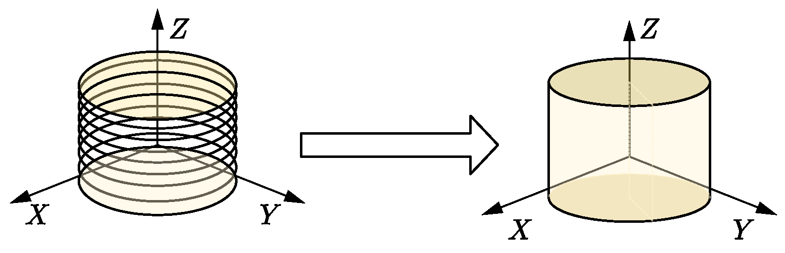
The stator core was formed by laminating axial silicon steel sheets, which cannot be simulated with actual structures when performing finite element modeling. Therefore, the special structure of the stator needs to be equivalent to an anisotropic material, and it was assumed that the axial direction of the motor was a continuous elastic body with uniform material. Figure 1 shows the equivalent model of the stator core.
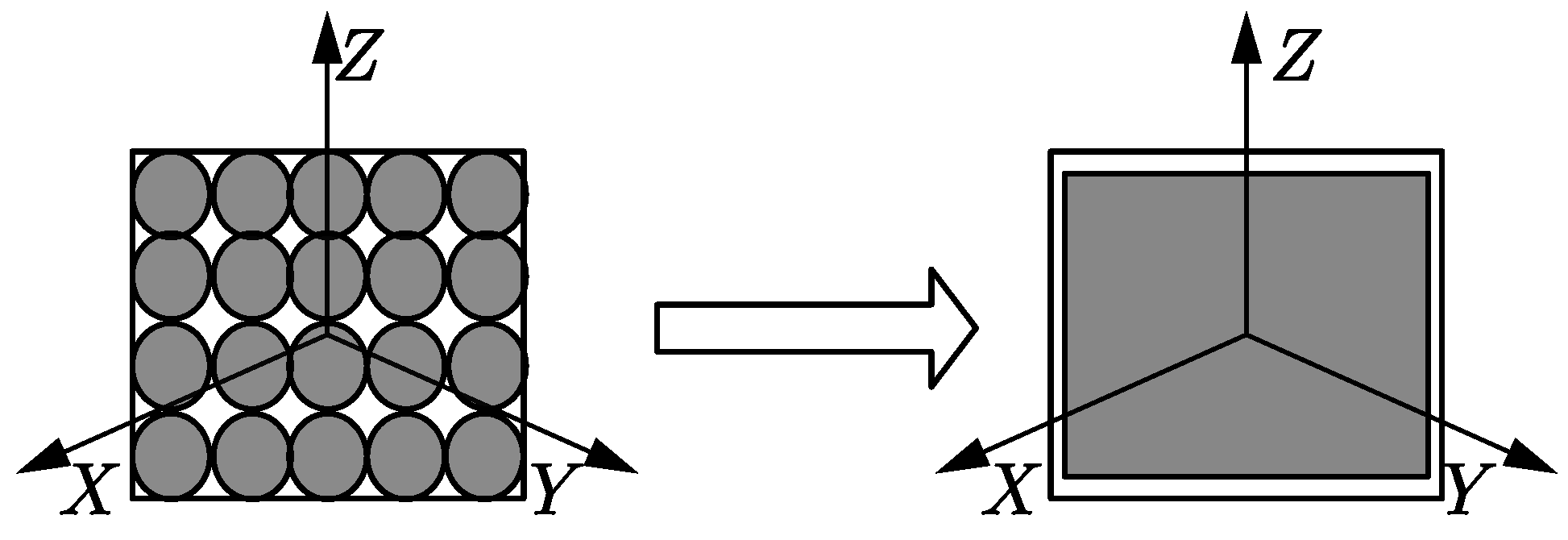
2.1.2. Simplification of Winding Finite Element Model
2.2. Parameter Setting of Stator System Materials
In this study, modal frequency calculation was analyzed by HyperMesh (14.0, Altair, Michigan, USA), a finite element preprocessing software from Altair. Table 1 shows the input parameters of anisotropic materials in HyperMesh software.
This modal experiment was carried out under constant temperature conditions, so the influence of temperature changes was ignored. Due to the large stiffness of the stator, the effect of the structural element damping coefficient (GE) on the natural frequency and mode shape was ignored [21]. According to the relationship of HyperMesh built-in material attribute parameters,
where σi is the normal stress of different squares, τij is the shear stress in different directions, εi is the longitudinal strain in different directions, and γij is the tangential strain in different directions.
The stator core was formed by laminating axial silicon steel sheets. Considering that the stator radial direction (parallel plane direction of the silicon steel sheet) was different than the axial (vertical silicon steel sheet direction) stiffness, it was considered that the silicon steel sheets had the same X and Y directions. The mechanical parameters were different from the Z-mechanical parameters. For the stator core, the material parameter properties were simplified:
The Gij shear modulus parameter can be set directly without adjusting the equivalent E (elasticity modulus), G, or Nu (Poisson’s ratio) value. By measuring the stator mass of 3 kg, according to the relationship between mass and volume, the actual density of the calculated stator core was 7680 kg/m3. We first referred to the material properties in the relevant literature and then converted them according to the Voigt–Reuss formula [22,23]. The approximate parameter initial value was set as shown in Table 2.
where vij is the Poisson’s ratio in different directions, and Ei is the elastic modulus in different directions.
2.3. Stator Core Material Property Equivalent Method
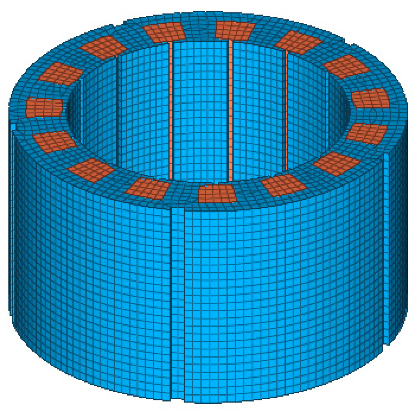
We used a 2.2 kW brushless DC motor as an example, and the influence of material properties on the natural frequency was analyzed. The basic parameters of the motor are shown in Table 3, and the equivalent model of the stator system is shown in Figure 3.
Table 4 shows the different core equivalent material parameters, where RHO is the material density. By changing the shear modulus Gij parameters, the modal changes were observed. The number 1-n in the table refers to changing the G11 parameter, while the other parameters remained unchanged; number 2-n refers to changing the G33 parameter, while the other parameters remained unchanged; number 3-n refers to changing the G44 parameter, while the other parameters remained unchanged; and number 4-n refers to changing the G55 parameter, while the other parameters remained unchanged. The effect of a single variable on the modal frequency was determined.
The effects of different parameters on the natural frequency are provided in Appendix A.
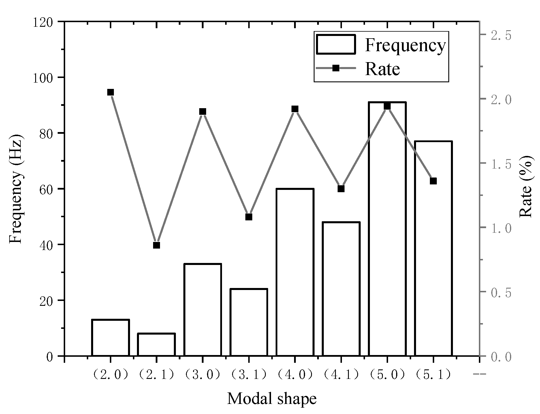
As shown in Figure 4, when the shear modulus G11 parameter was changed by 10,000, the frequency of the different mode modal frequencies changed. The abscissa represents the mode shape, and the ordinate represents the change value and relative change rate of the modal frequency. From the graph, the modes of the core modes (m, 0) and (m, 1) were proportional to the size of the shear modulus G11, the G11 parameters (m, 0) and (m, 1) were increased, and the frequency of the state had increased. The degree of change of the shear modulus G11 to (m, 0) was greater than (m, 1). The (m, 0) order change rate increased with the increase of the order, and the relative change gradually increased. For the (m, 0) mode, the shear modulus G11 had a greater influence on the higher order than the lower order, and the shear modulus G11 had the greatest influence on the (2, 0) order, which had a relative change rate of 2.05%. For the (m, 1) order mode, as the order increased, the relative rate of change gradually increased. Therefore, the shear modulus G11 had a greater influence on the higher order than the lower order.
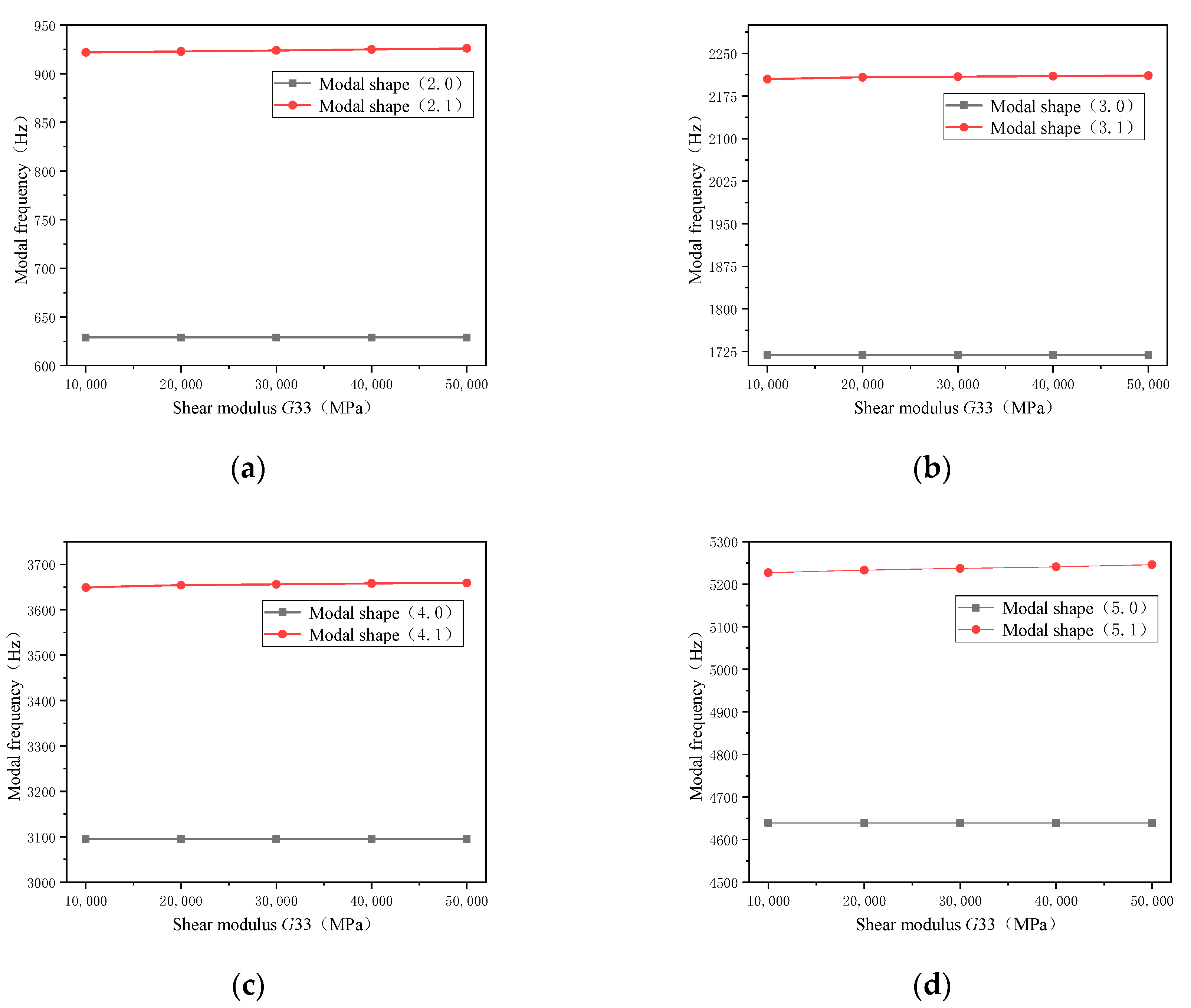
Figure 5 shows the degree of change of the modal frequency of different orders when the shear modulus G33 parameter was changed by 10,000. It can be seen from this that when changing the shear modulus G33, for the variation curve of each order mode frequency, changing the shear modulus G33 had less influence on the (m, 0) and (m, 1) order modal frequencies. The shear modulus G33 had no effect on the (m, 0) mode frequency. The influence on the (m, 1) order mode was also small, and the relative change rate was about 0.1%. Therefore, the influence of G33 on the modal frequency was small, and the change of the shear modulus G33 was not considered in the selection of the equivalent material.
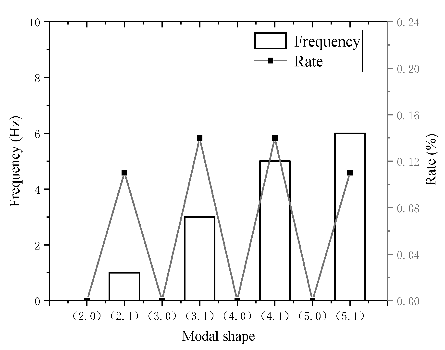
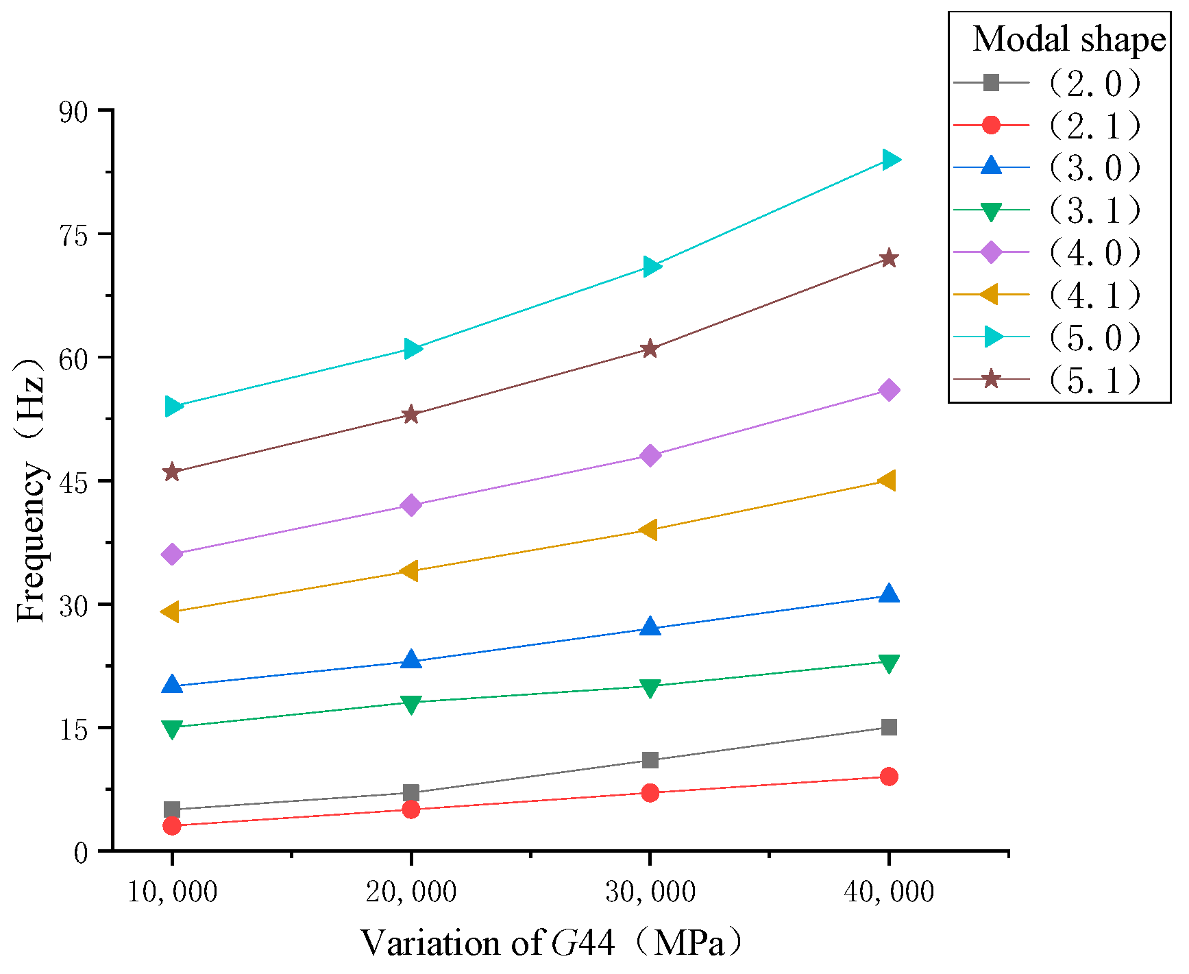
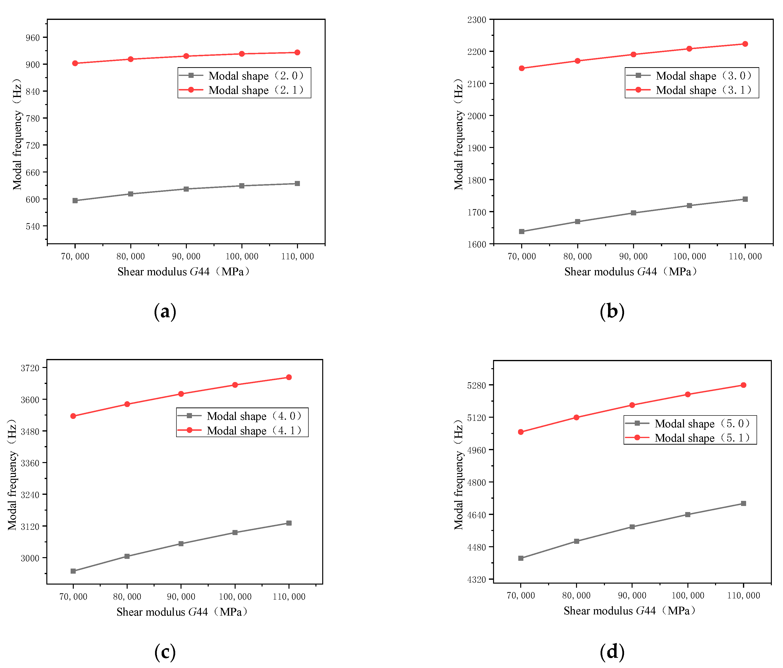
Figure 6 shows the effect of the change of shear modulus G44 on the modal frequencies of different orders. Taking the (2, 0) order in the figure as an example, when the shear modulus G44 was reduced by 10,000 MPa, the modal frequency was reduced by 5 Hz. When the shear modulus G44 was further reduced by 10,000 MPa, the modal frequency was reduced by 7 Hz, so the modal frequency change amount was the modal value relative to the former. It can be seen from the figure that, from a certain order, the modal frequency change gradually increased with the decrease of the shear modulus G44, and the smaller the G44 material parameter, the greater the influence of the change value on the modal frequency. From (m, 0) and (m, 1), the shear modulus G44 had a greater influence on the (m, 0) mode frequency. From the overall order, when the shear modulus was reduced by 10,000 MPa, the high-order modal frequency changed more.
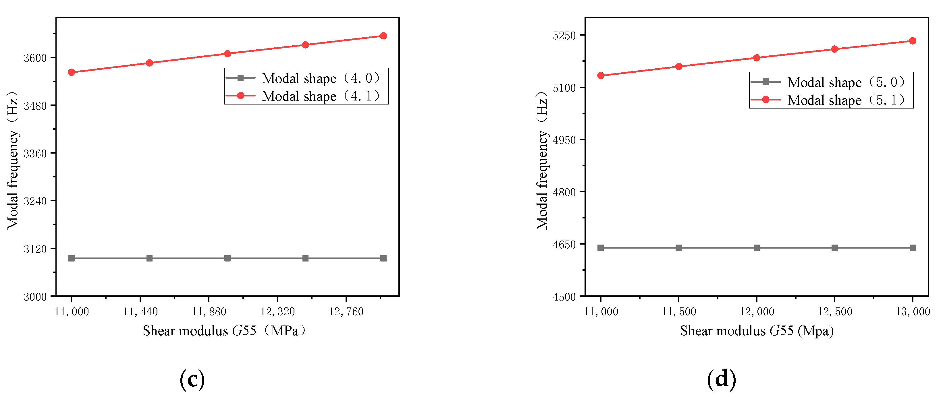
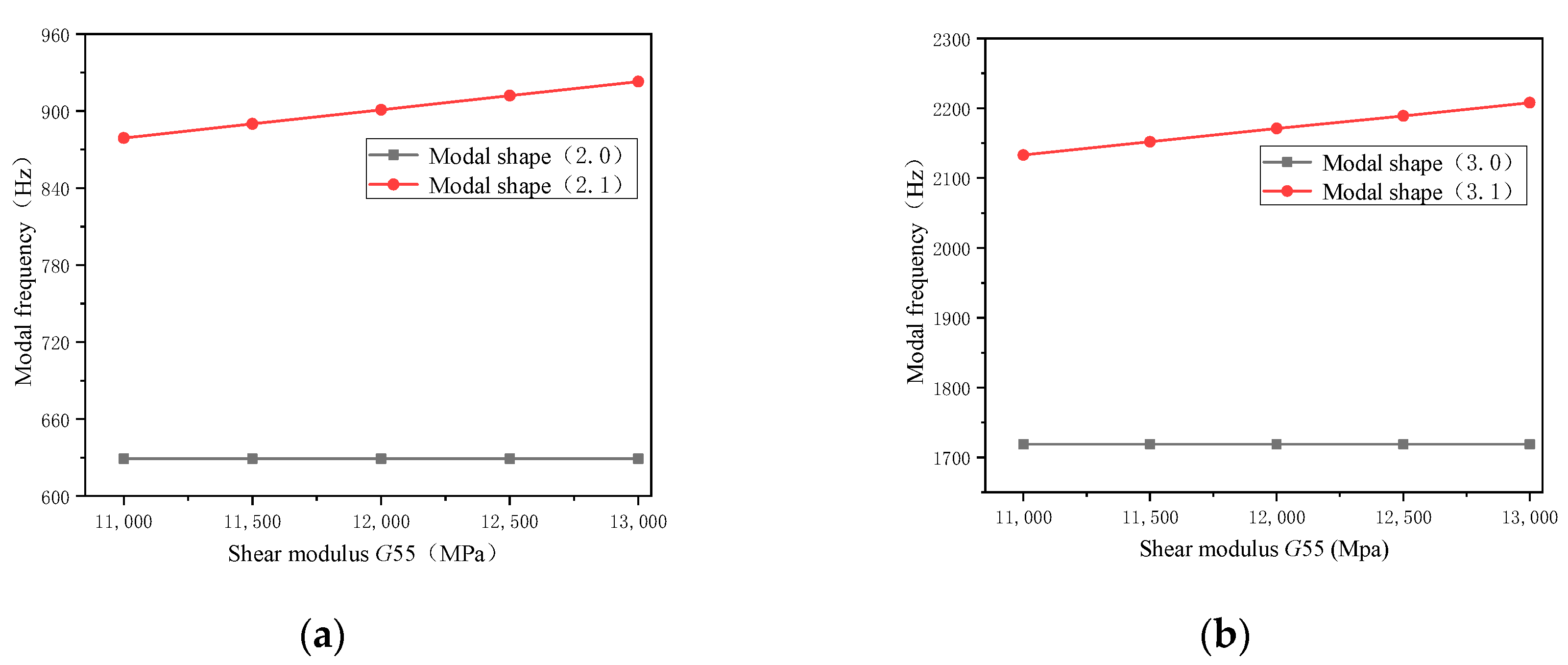
Figure 7 shows the degree of change of the modal frequency of different orders when the shear modulus G55 parameter was changed by 500. It can be seen that the shear modulus G55 had no effect on the (m, 0) mode frequency. The shear modulus G55 mainly affected the (m, 1) modal frequency, and as the order increased, the influence of the G55 parameter on its modal frequency variable rate gradually decreased. Therefore, the G55 parameter mainly affected the lower-order modal frequency of (m, 1).
2.4. Modal Testing Analysis
2.4.1. Modal Experiment of Stator Core
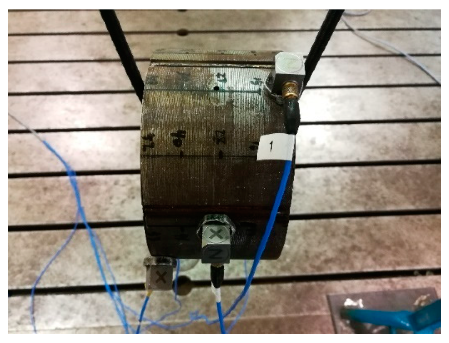
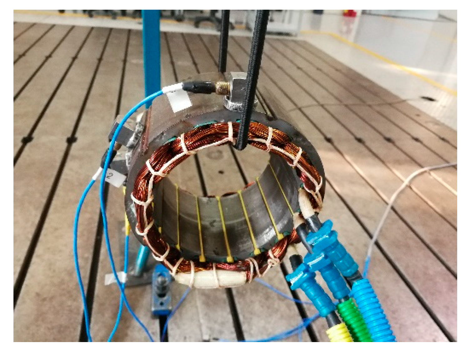
In order to ensure the accuracy of the finite element model, the stator core was subjected to free modal testing. Figure 8 shows the arrangement of the motor stator core modal experiment. The stator core was suspended by an elastic nylon rope to simulate the free mode of finite element simulation.
As shown in Figure 8, the stator core was evenly arranged with 12 excitation points in each layer in the radial direction, for a total of 60 excitation points, and four three-way acceleration sensors were arranged.
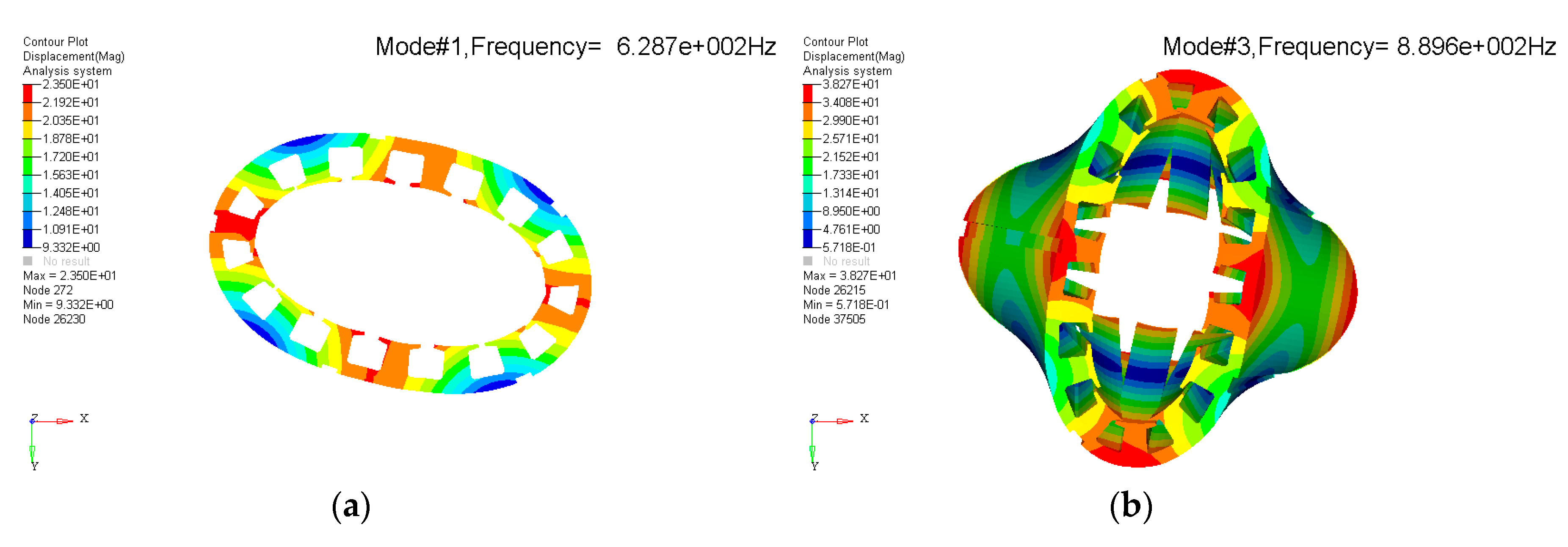
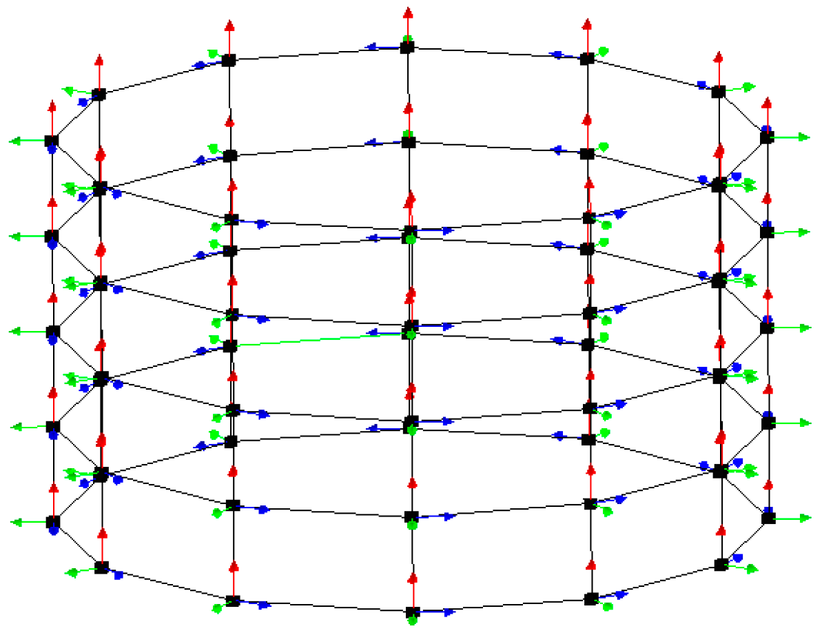
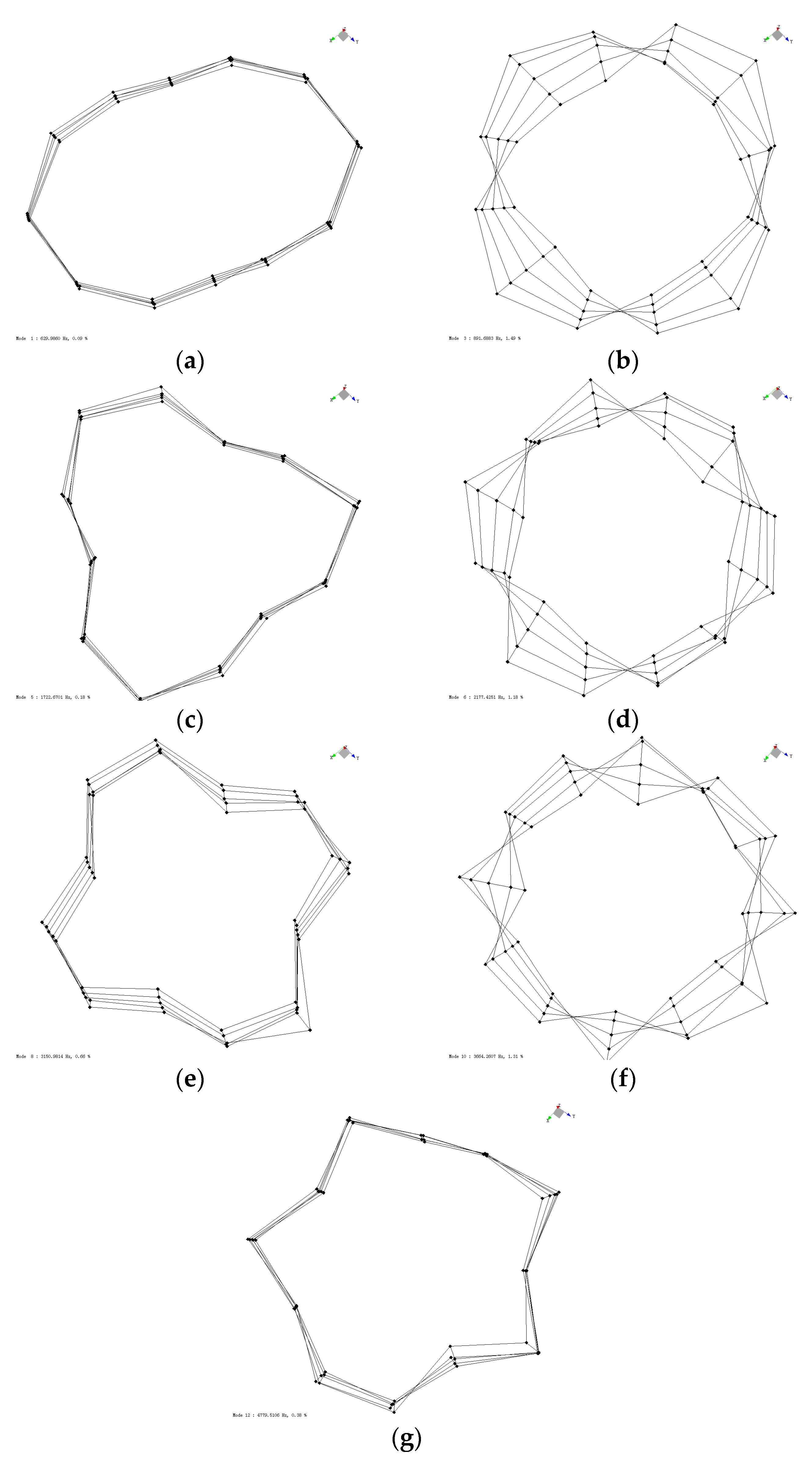
When using software for the measurements, we first set up the test model of the motor, input the coordinates of each measuring point, and connected 60 excitation points according to the actual structure of the motor, as shown in Figure 9. The modal test method was the hammer method, which entailed tapping on 60 excitation points. The vibration direction of the stator core was mainly radial circumferential vibration, so the vibration mode of the stator core could be obtained only by tapping the Z direction. When hammering the motor, each excitation point was tapped five times. When striking at the same point, we ensured that each force and direction was the same and then took the average of five test results to reduce the error. Figure 10 shows the first seven modal modes and modal frequencies of the stator core.
2.4.2. Modal Experiment of Stator Winding
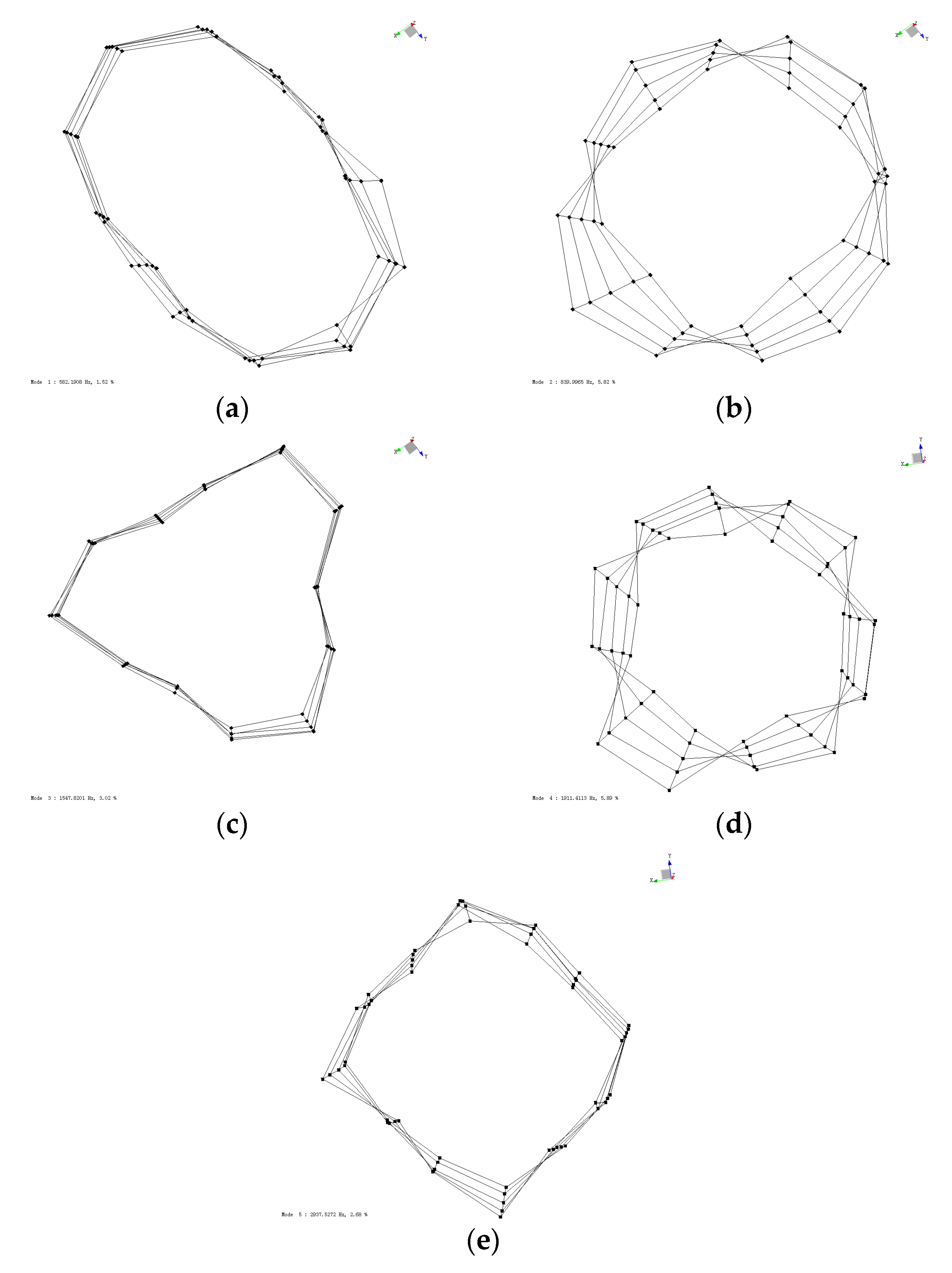
In order to further verify the accuracy of the equivalent parameter method, the stator windings were subjected to finite element analysis and modal experiments. Figure 11 shows the stator winding modal experiment. Figure 12 shows the first five mode shapes and frequencies obtained from the stator winding experiment.
3. Results
3.1. Correction Method of Anisotropic Material Parameters
Since the stator material was anisotropic, it was very difficult to test both the actual material of the stator material and the material properties of the stator finite element model. Therefore, in the actual finite element analysis, the material properties of the stator needed to be treated equivalently. By analyzing the influence of the material parameters on the modal frequencies of different orders, a method for correcting the parameters of the stator core material was derived.
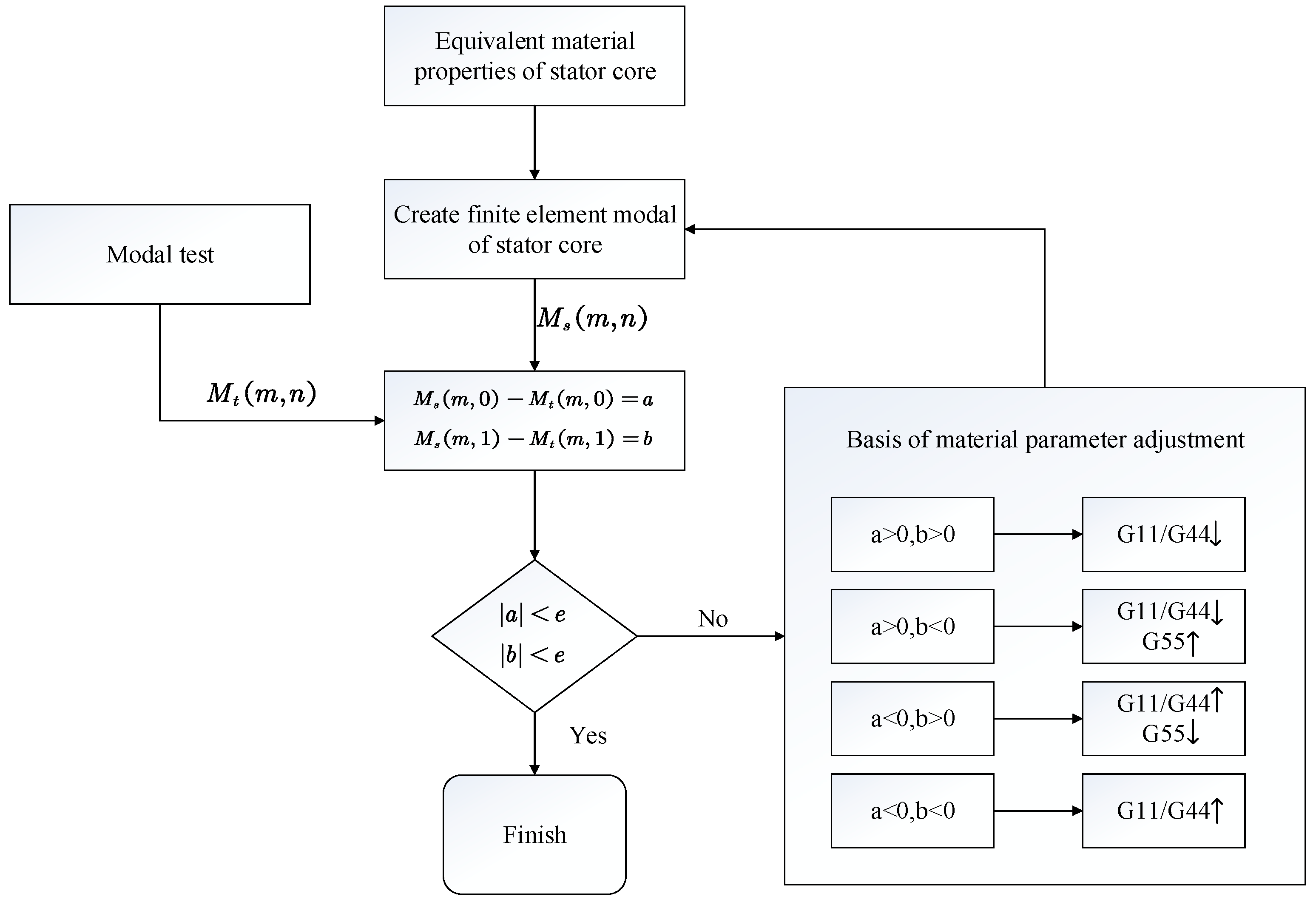
Figure 13 shows the anisotropic material parameter correction method. Firstly, the material parameters of the iron core were roughly calculated according to the empirical formula, and the initial modal results were calculated. Then, the simulation results were compared with the modal experimental results to generate the a and b relative errors. If the relative error was within the acceptable range, the core material parameters did not need to be adjusted. Otherwise, the material parameters were adjusted appropriately, referring to the material parameter adjustment basis shown in Figure 13, in which Ms (m,n) is the finite element modals initial result, Mt (m,n) is the experimental result, a is the relative error of M (m,0), b is the relative error of M (m,1), and e is an acceptable error range.
3.2. Modal Testing Results
3.2.1. Modal Testing Results of Stator Core
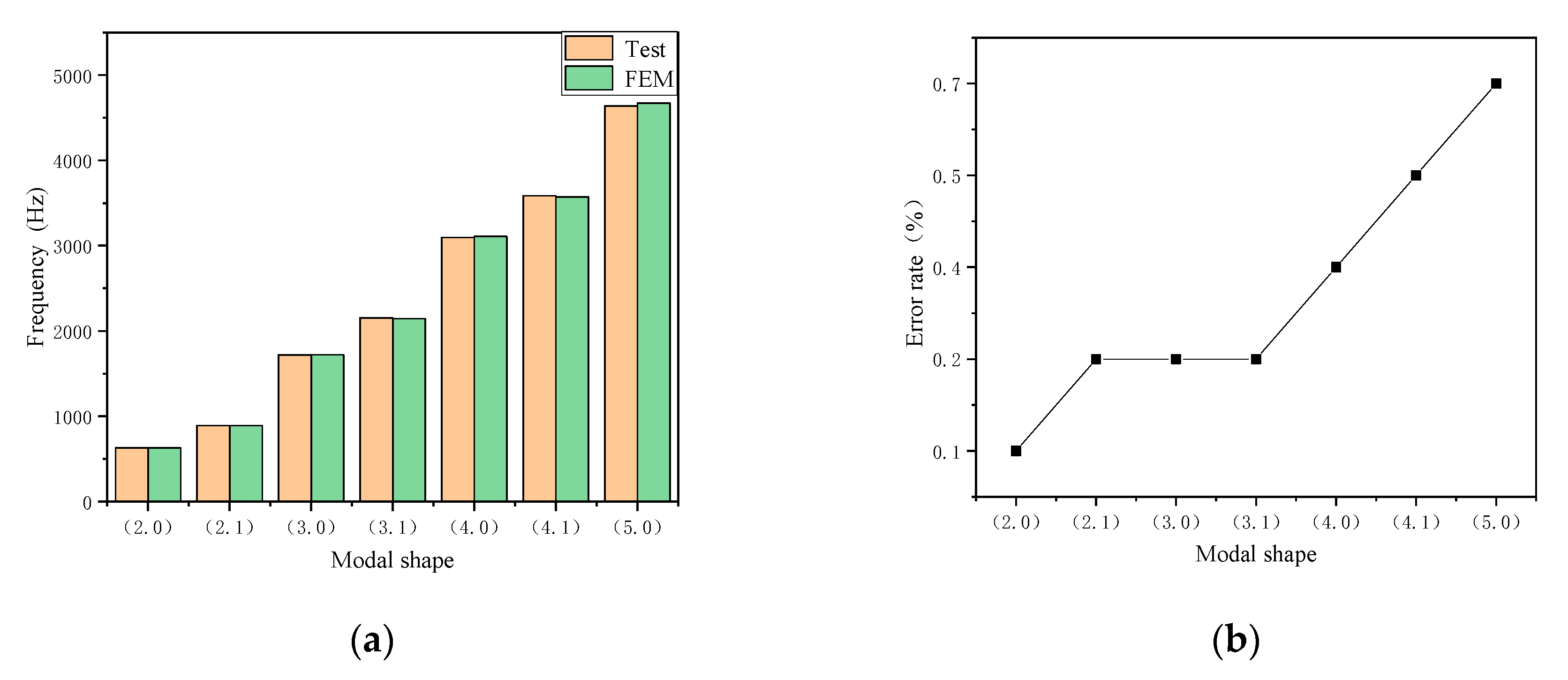
The material parameters of the finite element simulation stator were G11 = G22 = 195,000 MPa, G33 = 20,000 MPa, G44 = 10,000 MPa, and G55 = G66 = 11,500 MPa. According to the comparison of the modal experiment results and the simulation results of the stator core (Figure 14), the finite element simulation frequency and mode were very close to the experimental results, and the errors were all below 1.0%. It was proved that the anisotropic material can accurately predict the modal frequencies and modes of a stator core.
The FE simulations of the stator core are provided in Appendix B.
3.2.2. Modal Testing Results of Stator Winding
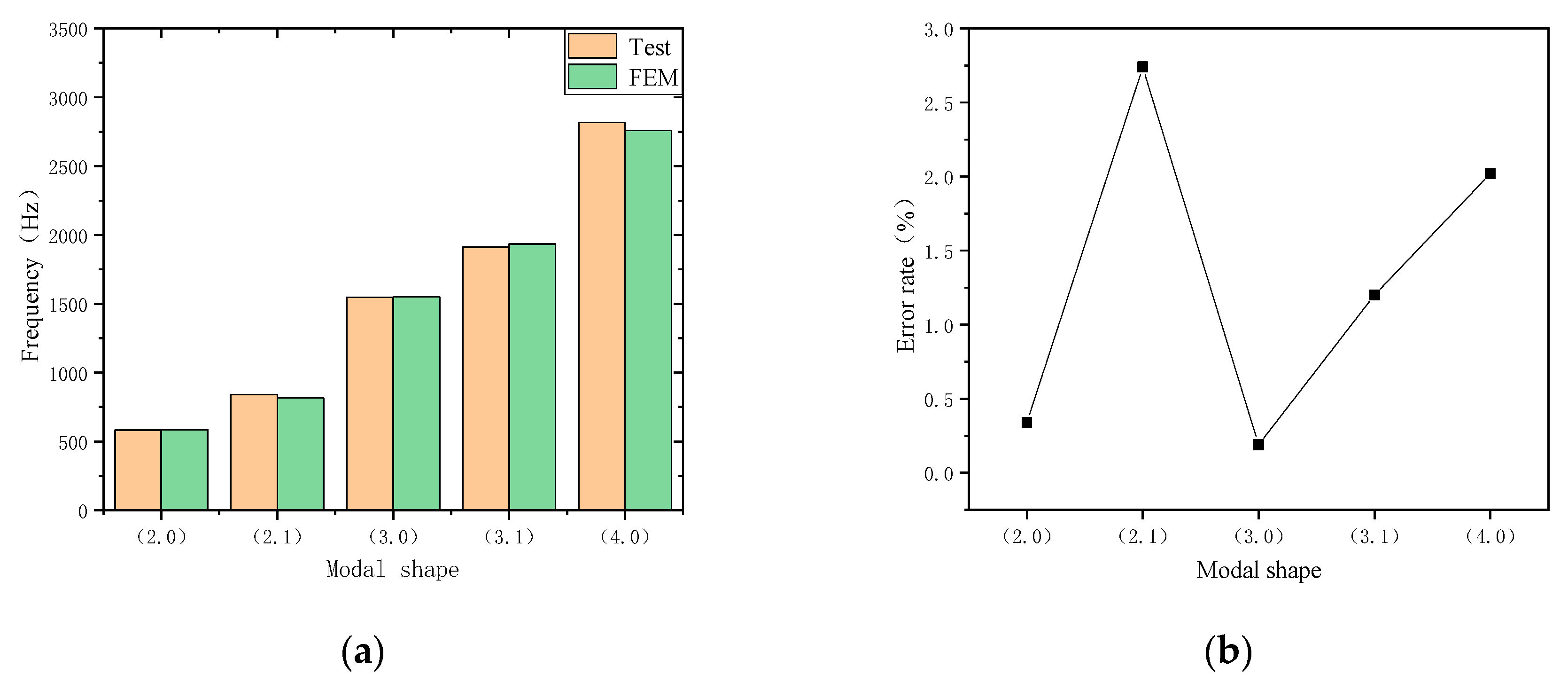
Through the analysis of the above-discussed finite element method, the materials of the anisotropy of the winding were calculated as G11 = G22 = 200 MPa, G33 = 100 MPa, G44 = 10 MPa, and G55 = G66 = 20 MPa. Figure 15 shows the results of the stator winding modal test and the finite element simulation. The simulation and experimental errors were within 3%, demonstrating that the equivalent mode of the anisotropic material can be used to accurately predict the modal frequencies and modes of the stator.
The FE simulations of the stator winding are provided in Appendix C.
4. Discussion
In this study, the stator system was simplified first, and the material parameters of the stator core were initially estimated. Secondly, the material parameters and modal frequencies were analyzed, and the parameter correction methods of stator anisotropic materials based on modal frequency were summarized. Finally, the modal test of the stator core and stator windings was completed by the hammering method, and the simulation and experimental results were compared. The error was within 3%, which guarantees the accuracy of the finite model and lays a foundation for calculating the electromagnetic noise of the motor. The following conclusions were obtained:
- (1)
- The analysis showed that the modal frequency was sensitive to material properties. The shear modulus G11 parameter affected the (m, 0) and (m, 1) modal frequencies. The shear modulus G33 parameter affected the (m, 1) modal frequency. The shear modulus G44 parameter affected the (m, 0) and (m, 1) modal frequencies. The shear modulus G55 parameter affected the (m, 1) modal frequency.
- (2)
- The effect of shear modulus G11 on (m, 0) was greater than that on (m, 1), and the effect on the higher order was greater than that on the lower order. The shear modulus G44 had a greater influence on the modal frequency than G11, and the modal frequency changed gradually as the material parameters decreased. The lower order (m, 1) was more sensitive to the shear modulus G55 parameter than the higher order.
- (3)
- The anisotropic material properties of the stator can guarantee the accuracy of the finite element model. The anisotropic material parameter correction method proposed in this paper can quickly determine the equivalent material parameters of a stator and winding.
Author Contributions
Conceptualization, Z.Z. and Z.J.; methodology, Z.Z.; software, Z.Z.; validation, Z.J. and Z.Z.; formal analysis, Y.Y.; investigation, Z.Z.; resources, Z.J.; data curation, Z.Z.; writing—original draft preparation, Z.Z.; writing—review and editing, Z.Z.; visualization, Z.Z.; supervision, H.X.; project administration, Z.Z.; funding acquisition, Z.J.
Funding
This research received no external funding.
Acknowledgments
The author’s express their gratitude to the Automotive Engineering Research Institute of China Automotive Technology and Research Center Co., Ltd. for providing the experimental places and instruments.
Conflicts of Interest
The authors declare no conflict of interest.
Appendix A
A single variable was controlled and the relationship between the natural frequency and the parameters was observed.
Figure A1.
Stator core natural frequency with shear modulus G11: (a) modal shape (2, n); (b) modal shape (3, n); (c) modal shape (4, n), and (d) modal shape (5, n).
Figure A1.
Stator core natural frequency with shear modulus G11: (a) modal shape (2, n); (b) modal shape (3, n); (c) modal shape (4, n), and (d) modal shape (5, n).
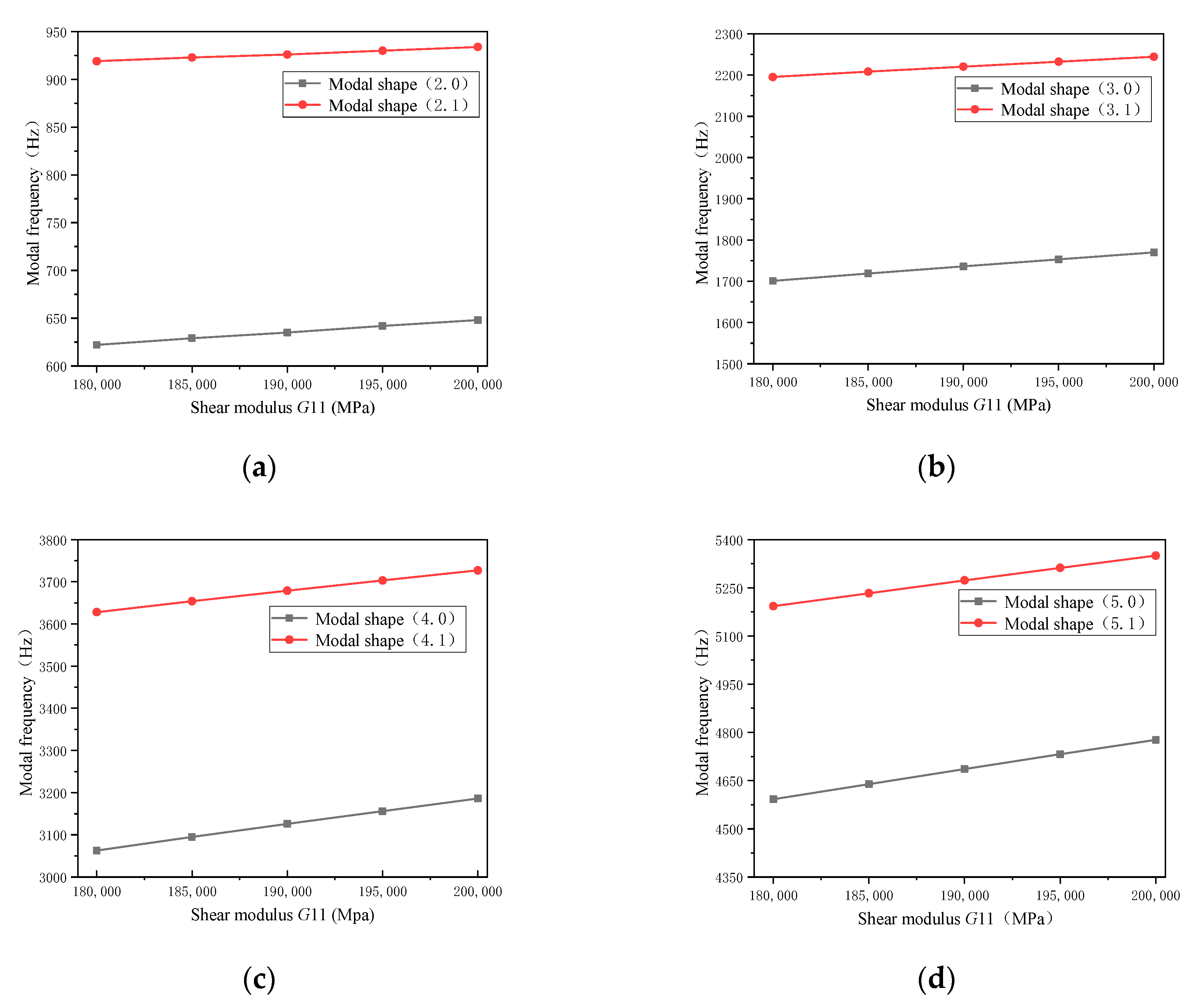
Figure A2.
Stator core natural frequency with shear modulus G33: (a) modal shape (2, n), (b) modal shape (3, n), (c) modal shape (4, n), and (d) modal shape (5, n).
Figure A2.
Stator core natural frequency with shear modulus G33: (a) modal shape (2, n), (b) modal shape (3, n), (c) modal shape (4, n), and (d) modal shape (5, n).

Figure A3.
Stator core natural frequency with shear modulus G44: (a) modal shape (2, n), (b) modal shape (3, n), (c) modal shape (4, n), and (d) modal shape (5, n).
Figure A3.
Stator core natural frequency with shear modulus G44: (a) modal shape (2, n), (b) modal shape (3, n), (c) modal shape (4, n), and (d) modal shape (5, n).

Figure A4.
Stator core natural frequency with shear modulus G55: (a) modal shape (2, n), (b) modal shape (3, n), (c) modal shape (4, n), and (d) modal shape (5, n).
Figure A4.
Stator core natural frequency with shear modulus G55: (a) modal shape (2, n), (b) modal shape (3, n), (c) modal shape (4, n), and (d) modal shape (5, n).

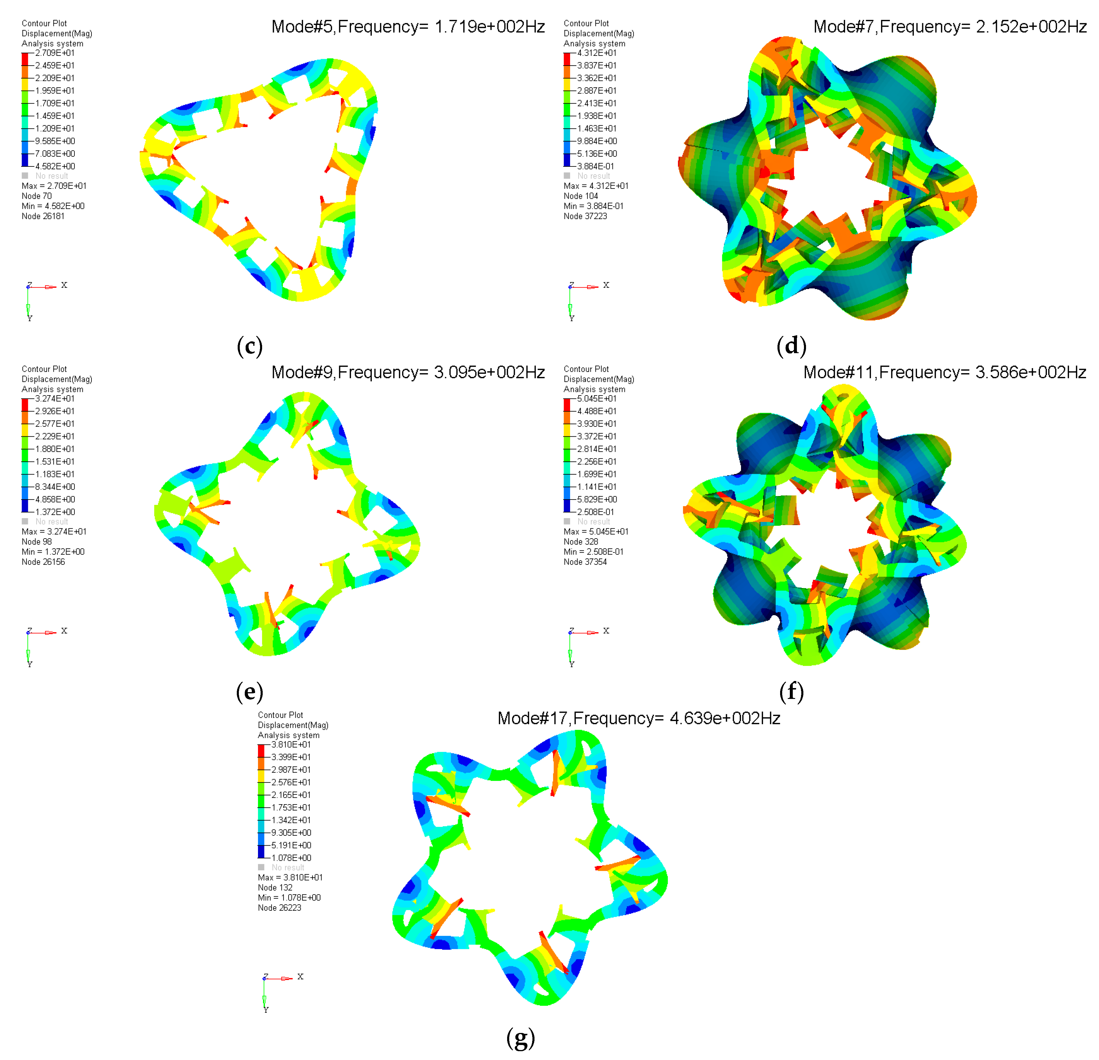
Appendix B
Modal calculation result of stator core.
Figure A5.
Modal calculation result of stator core: (a) modal shape (2.0), (b) modal shape (2.1), (c) modal shape (3.0), (d) modal shape (3.1), (e) modal shape (3.1), (f) modal shape (3.1), and (g) modal shape (3.1).
Figure A5.
Modal calculation result of stator core: (a) modal shape (2.0), (b) modal shape (2.1), (c) modal shape (3.0), (d) modal shape (3.1), (e) modal shape (3.1), (f) modal shape (3.1), and (g) modal shape (3.1).

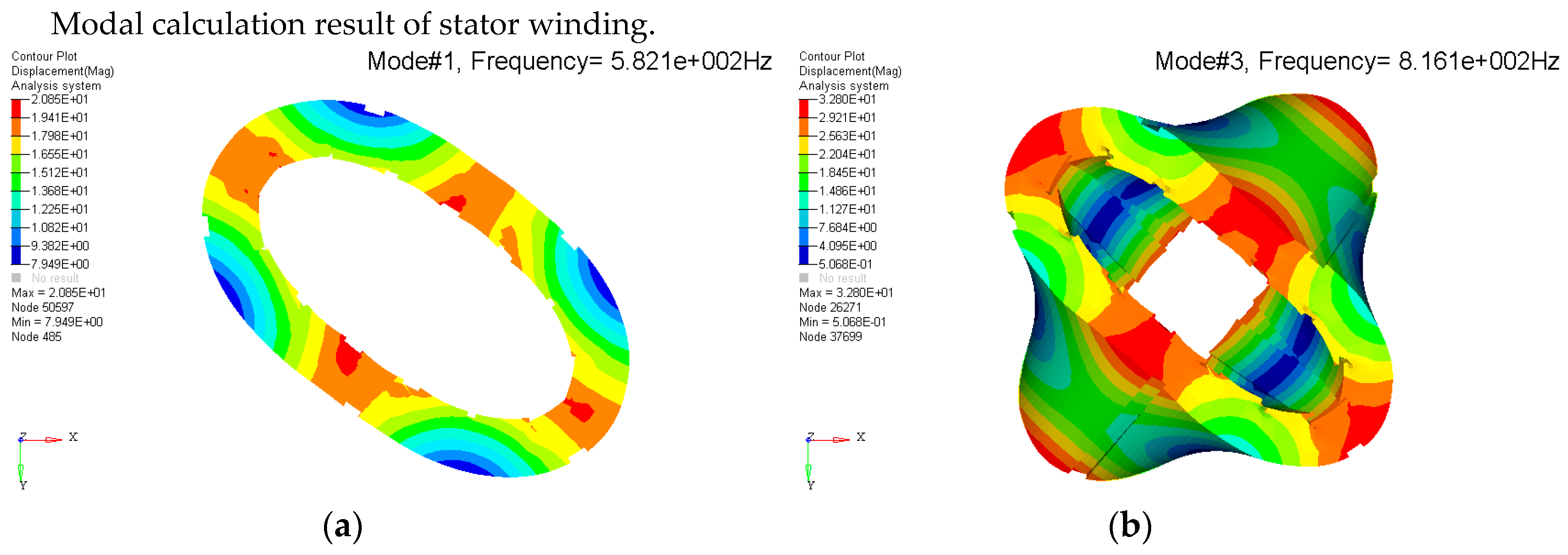
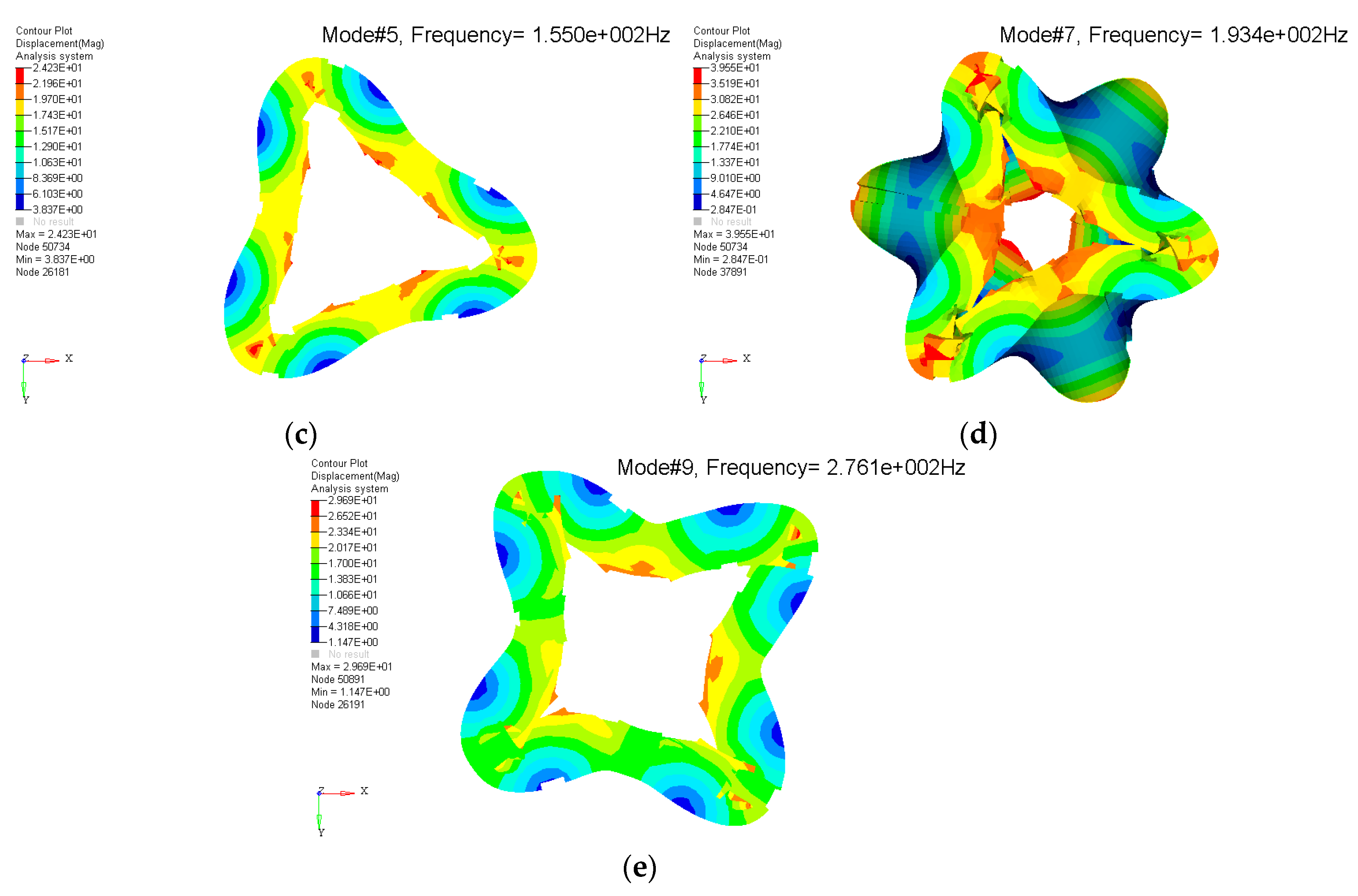
Appendix C
Modal calculation result of stator winding.
Figure A6.
Modal calculation result of stator winding: (a) modal shape (2.0), (b) modal shape (2.1), (c) modal shape (3.0), (d) modal shape (3.1), and (e) modal shape (3.1).
Figure A6.
Modal calculation result of stator winding: (a) modal shape (2.0), (b) modal shape (2.1), (c) modal shape (3.0), (d) modal shape (3.1), and (e) modal shape (3.1).


References
- Takeno, M.; Chiba, A.; Hoshi, N.; Ogasawara, S.; Takemoto, M.; Rahman, M.A. Test results and torque improvement of the 50-kw switched reluctance motor designed for hybrid electric vehicles. IEEE Trans. Ind. Appl. 2012, 48, 1327–1334. [Google Scholar] [CrossRef]
- Cheng, H.; Chen, H.; Yang, Z. Design indicators and structure optimisation of switched reluctance machine for electric vehicles. IET Electr. Power Appl. 2015, 9, 319–331. [Google Scholar] [CrossRef]
- Radimov, N.; Ben-Hail, N.; Rabinovici, R. Switched reluctance machines as three-phase AC autonomous generator. IEEE Trans. Magn. 2006, 42, 3760–3764. [Google Scholar] [CrossRef]
- Djelloul-Khedda, Z.; Boughrara, K.; Dubas, F.; Ibtiouen, R. Nonlinear Analytical Prediction of Magnetic Field and Electromagnetic Performances in Switched Reluctance Machines. IEEE Trans. Magn. 2017, 53, 1–11. [Google Scholar] [CrossRef]
- Liang, X.; Li, G.; Ojeda, J.; Gabsi, M.; Ren, Z. Comparative Study of Classical and Mutually Coupled Switched Reluctance Motors Using Multiphysics Finite-Element Modeling. IEEE Trans. Ind. Electron. 2013, 61, 5066–5074. [Google Scholar] [CrossRef]
- Lin, F.; Zuo, S.; Deng, W.; Wu, S. Modeling and Analysis of Electromagnetic Force, Vibration, and Noise in Permanent-Magnet Synchronous Motor Considering Current Harmonics. IEEE Trans. Ind. Electron. 2016, 63, 7455–7466. [Google Scholar] [CrossRef]
- Torregrossa, D.; Khoobroo, A.; Fahimi, B. Prediction of Acoustic Noise and Torque Pulsation in PM Synchronous Machines with Static Eccentricity and Partial Demagnetization Using Field Reconstruction Method. IEEE Trans. Ind. Electron. 2012, 59, 934–944. [Google Scholar] [CrossRef]
- Santos, F.L.M.D.; Anthonis, J.; Naclerio, F.; Gyselinck, J.J.C.; van der Auweraer, H.; Goes, L.C.S. Multiphysics NVH Modeling: Simulation of a Switched Reluctance Motor for an Electric Vehicle. IEEE Trans. Ind. Electron. 2014, 61, 469–476. [Google Scholar] [CrossRef]
- Fleck, N.A.; Deshpande, V.S. The resistance of clamped sandwich beams to shock loading. J. Appl. Mech. 2004, 71, 386–401. [Google Scholar] [CrossRef]
- Rosca, I.C.; Filip, M.; Helerea, E. Three-phase squirrel-cage induction motor modal analyses. Theoretical and experimental aspects. In Proceedings of the 13th International Conference on Optimization of Electrical and Electronic Equipment (OPTIM), Brasov, Romania, 24–26 May 2012. [Google Scholar]
- Ying, X.; Yan, W.; Sen, L.; Hongyan, G.; Haisong, L. Modal calculation and test of small asynchronous motor. Transl. China Electrotech. Soc. 2015, 30, 1–9. [Google Scholar]
- Bao, X.; Liu, J.; Ni, Y.; Liu, B. Modal analysis and natural frequency calculation of the stator in automotive claw-pole alternator. Automot. Eng. 2011, 33, 1088–1091. [Google Scholar]
- Zuo, S.G.; Zhang, Y.; Yan, J.; Zhang, G.; Lin, F.; Wu, S. Optimization of vibration and noise in permanent magnet synchronous motor considering stator anisotropy. Xi’an Jiaotong Univ. Xuebao 2017, 51, 60–68. [Google Scholar]
- Guo, X.; Zhong, R.; Zhang, M.; Ding, D.; Sun, W. Fast computation of radial vibration in switched reluctance motors. IEEE Trans. Ind. Electron. 2018, 65, 4588–4598. [Google Scholar] [CrossRef]
- Schlegl, B.; Schönleitner, F.; Marn, A.; Neumayer, F.; Heitmeir, F. Analytical determination of the orthotropic material behavior of stator bars in the range of the end windings and determination of the material characteristics of the orthotropic composite space brackets via experimental modal analysis and FE-calculation. In Proceedings of the International Conference on Electrical Machines, Marseille, France, 2–5 September 2012. [Google Scholar]
- Hu, S.; Zuo, S.; Liu, M.; Wu, H. Method for acquisition of equivalent material parameters considering orthotropy of stator core and windings in SRM. IET Electr. Power Appl. 2019, 13, 580–586. [Google Scholar] [CrossRef]
- Sun, J.J.; Feng, H.J.; Zhu, C.S. Identification of laminated core and winding’s physical parameters by stator’s modal testings. In Proceedings of the 17th International Conference on Electrical Machines and Systems (ICEMS), Hangzhou, China, 22–25 October 2014. [Google Scholar]
- Mcmeeking, R.; Spuskanyuk, A.; He, M.; Deshpande, V.; Fleck, N.; Evans, A. An analytical model for the response to water blast of unsupported metallic sandwich panels. Int. J. Solids Struct. 2008, 45, 478–496. [Google Scholar] [CrossRef]
- Yin, H.; Ma, F.; Zhang, X.; Gu, C.; Gao, H.; Wang, Y. Research on Equivalent Material Properties and Modal Analysis Method of Stator System of Permanent Magnet Motor with Concentrated Winding. IEEE Access 2019, 7, 64592–64602. [Google Scholar] [CrossRef]
- Kirschneck, M.; Rixen, D.; Polinder, H. Model Reduction Methods for Magnetic Fields Based on Modal Analysis. IEEE Trans. Magn. 2014, 50, 1–4. [Google Scholar] [CrossRef]
- Chen, Y.X.; Zhu, Z.Q.; Ying, S.C. Analysis and Control of Motor Noise; Zhejiang University Press: Hangzhou, China, 1987; Volume 1, pp. 36–37. ISBN 7-308-00025-7. [Google Scholar]
- Chai, F.; Li, Y.; Pei, Y.; Li, Z. Accurate modelling and modal analysis of stator system in permanent magnet synchronous motor with concentrated coils for vibration prediction. IET Electr. Power Appl. 2018, 12, 1225–1232. [Google Scholar] [CrossRef]
- Chen, Y.H.; Ding, T.H.; Tian, L. Research on calculation method of motor lamination core vibration characteristics. Electr. Mach. Control 2014, 18, 71–76. [Google Scholar]
Figure 1.
Equivalent model of the stator core.

Figure 2.
Equivalent model of stator winding.

Figure 3.
Finite element model of stator system.

Figure 4.
Effect of shear modulus G11 on modal frequency.

Figure 5.
Effect of shear modulus G33 on modal frequency.

Figure 6.
Influence of shear modulus G44 on modal.

Figure 7.
Effect of shear modulus G55 on modal frequency.
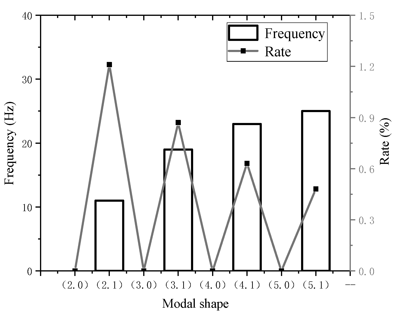
Figure 8.
Stator core modal experiment.

Figure 9.
Experimental test model.

Figure 10.
Stator core mode shape and frequency: (a) modal shape (2.0); (b) modal shape (2.1); (c) modal shape (3.0); (d) modal shape (3.1); (e) modal shape (4.0); (f) modal shape (4.1), and (g) modal shape (5.0).
Figure 10.
Stator core mode shape and frequency: (a) modal shape (2.0); (b) modal shape (2.1); (c) modal shape (3.0); (d) modal shape (3.1); (e) modal shape (4.0); (f) modal shape (4.1), and (g) modal shape (5.0).

Figure 11.
Modal experiment of stator winding.

Figure 12.
Stator core mode shape and frequency: (a) modal shape (2.0); (b) modal shape (2.1); (c) modal shape (3.0); (d) modal shape (3.1); (e) modal shape (4.0).
Figure 12.
Stator core mode shape and frequency: (a) modal shape (2.0); (b) modal shape (2.1); (c) modal shape (3.0); (d) modal shape (3.1); (e) modal shape (4.0).

Figure 13.
Correction method of anisotropic material parameters.

Figure 14.
Comparison of finite element analysis and experiment of stator core: (a) modal frequency and (b) error analysis.
Figure 14.
Comparison of finite element analysis and experiment of stator core: (a) modal frequency and (b) error analysis.

Figure 15.
Results of modal experiment and simulation of stator winding: (a) modal frequency and (b) error analysis.
Figure 15.
Results of modal experiment and simulation of stator winding: (a) modal frequency and (b) error analysis.


Table 1.
Definitions of anisotropic material properties.
| Parameter | Definition |
|---|---|
| RHO | Mass density |
| Gij | The material property matrix |
| Ai | Thermal expansion coefficient vector |
| TREF | Reference temperature |
| GE | Structural element damping coefficient |
Table 2.
Equivalent mechanical parameters of stator structure.
| Parameter | Unit | Stator Core |
|---|---|---|
| RHO | g·m-3 | 7680 |
| G11 | MPa | 200,000 |
| G33 | MPa | 20,000 |
| G44 | MPa | 100,000 |
| G55 | Mpa | 13,000 |
Table 3.
Machine parameters.
| Parameter | Unit | Value |
|---|---|---|
| Number of poles | / | 5 |
| Number of stator slots | / | 15 |
| Number of phases | / | 3 |
| Stator outer/inner diameter | mm | 140/99.6 |
| Rotor outer/inner diameter | mm | 98.6/30 |
| Active axial length | mm | 77.5 |
| Rated power | kW | 2.2 |
| Winding | / | Concentrated |
| Coil turns | / | 3 |
Table 4.
Equivalent material parameters of stator core.
| Parameter | RHO | G11 | G33 | G44 | G55 |
|---|---|---|---|---|---|
| ID | |||||
| 1-1 | 7680 | 200,000 | 20,000 | 100,000 | 13,000 |
| 1-2 | 7680 | 195,000 | 20,000 | 100,000 | 13,000 |
| 1-3 | 7680 | 190,000 | 20,000 | 100,000 | 13,000 |
| 1-4 | 7680 | 185,000 | 20,000 | 100,000 | 13,000 |
| 1-5 | 7680 | 180,000 | 20,000 | 100,000 | 13,000 |
| 2-1 | 7680 | 185,000 | 50,000 | 100,000 | 13,000 |
| 2-2 | 7680 | 185,000 | 40,000 | 100,000 | 13,000 |
| 2-3 | 7680 | 185,000 | 30,000 | 100,000 | 13,000 |
| 2-4 | 7680 | 185,000 | 20,000 | 100,000 | 13,000 |
| 2-5 | 7680 | 185,000 | 10,000 | 100,000 | 13,000 |
| 3-1 | 7680 | 185,000 | 20,000 | 110,000 | 13,000 |
| 3-2 | 7680 | 185,000 | 20,000 | 100,000 | 13,000 |
| 3-3 | 7680 | 185,000 | 20,000 | 90,000 | 13,000 |
| 3-4 | 7680 | 185,000 | 20,000 | 80,000 | 13,000 |
| 3-5 | 7680 | 185,000 | 20,000 | 70,000 | 13,000 |
| 4-1 | 7680 | 185,000 | 20,000 | 100,000 | 13,000 |
| 4-2 | 7680 | 185,000 | 20,000 | 100,000 | 12,500 |
| 4-3 | 7680 | 185,000 | 20,000 | 100,000 | 12,000 |
| 4-4 | 7680 | 185,000 | 20,000 | 100,000 | 11,500 |
| 4-5 | 7680 | 185,000 | 20,000 | 100,000 | 11,000 |
© 2019 by the authors. Licensee MDPI, Basel, Switzerland. This article is an open access article distributed under the terms and conditions of the Creative Commons Attribution (CC BY) license (http://creativecommons.org/licenses/by/4.0/).
Share and Cite
MDPI and ACS Style
Zhang, Z.; Jiao, Z.; Xia, H.; Yao, Y. Parameter Equivalent Method of Stator Anisotropic Material Based on Modal Analysis. Energies 2019, 12, 4257. https://doi.org/10.3390/en12224257
AMA Style
Zhang Z, Jiao Z, Xia H, Yao Y. Parameter Equivalent Method of Stator Anisotropic Material Based on Modal Analysis. Energies. 2019; 12(22):4257. https://doi.org/10.3390/en12224257
Chicago/Turabian StyleZhang, Zeyu, Zhiyong Jiao, Hongbing Xia, and Yuhan Yao. 2019. "Parameter Equivalent Method of Stator Anisotropic Material Based on Modal Analysis" Energies 12, no. 22: 4257. https://doi.org/10.3390/en12224257
Note that from the first issue of 2016, this journal uses article numbers instead of page numbers. See further details here.