Experimental Investigations on the Inner Flow Behavior of Centrifugal Pumps under Inlet Air-Water Two-Phase Conditions
by
 ,
,
Qiaorui Si
1,* ,
,
Haoyang Zhang
1,
Gérard Bois
2,
Jinfeng Zhang
1,
Qianglei Cui
1 and
Shouqi Yuan
1,* 1
National Research Center of Pumps, Jiangsu University, Zhenjiang 212013, China
2
LMFL, FRE CNRS 3723, Arts et Métiers ParisTech, 59046 Lille, France
*
Authors to whom correspondence should be addressed.
Energies 2019, 12(22), 4377; https://doi.org/10.3390/en12224377
Submission received: 27 October 2019
/
Revised: 11 November 2019
/
Accepted: 14 November 2019
/
Published: 17 November 2019
(This article belongs to the Special Issue Advancements in Multiphase Fluid Dynamics in Energy and Propulsion Systems)
Abstract
:Centrifugal pumps are widely used and are known to be sensitive to inlet air-water two-phase flow conditions. The pump performance degradation mainly depends on the changes in the two-phase flow behavior inside the pump. In the present paper, experimental overall pump performance tests were performed for two different rotational speeds and several inlet air void fractions (αi) up to pump shut-off condition. Visualizations were also performed on the flow patterns of a whole impeller passage and the volute tongue area to physically understand pump performance degradation. The results showed that liquid flow modification does not follow head modification as described by affinity laws, which are only valid for homogeneous bubbly flow regimes. Three-dimensional effects were more pronounced when inlet void fraction increased up to 3%. Bubbly flow with low mean velocities were observed close to the volute tongue for all αi, and returned back to the impeller blade passages. The starting point of pump break down was related to a strong inward reverse flow that occurred in the vicinity of the shroud gap between the impeller and volute tongue area.
1. Introduction
Centrifugal pumps are widely used in fluid transportation fields, such as energy, chemical, and aerospace, in which always exist gas-liquid two-phase flow phenomena. It is well known that pump performance often fails when gas entrained compared to signal one-phase flow. Several attempts have been proposed by researchers to evaluate pump performance degradation under two-phase flow conditions, particularly for centrifugal pumps. The first basic analysis was performed by Murakami et al. [1,2] in 1974. A one-dimensional two-phase flow model was developed by Minemura et al. [3,4]. In 1995, Noghrehkar et al. [5] investigated the effect of water temperature and high void fraction in relation to churn flow pattern. However, most research is based on the assumption of bubbly homogeneous flow regimes, which can be observed up to an inlet void fraction not exceeding 4% to 5% depending on the pump geometry and operating conditions. However, conventional designs of centrifugal pumps could work with a maximum of 12% inlet void fraction under design working conditions, as shown by Jiang et al. [6]. The handling ability of centrifugal pumps for gas entraining is still confusing for pump designers, which is related to the two-phase flow behaviors inside the impeller and volute passage.
For low-flow rate off-design conditions, pump head capacity curves may exhibit a positive slope (instead of the usual negative slope corresponding to the normal operating range), which usually corresponds to increased pump surging phenomena onsets with the so-called “agglomerated and/or gas pocket” flow pattern. On the contrary, higher flow rate conditions may allow the pump to still transport mixtures when the so-called “segregated flow” pattern is present. A literature survey of the experimental studies indicated that additional losses or apparent losses mainly take place inside the rotating part of the pump (Murakami et al. [2]). Bubble size has been found to play an important role in affecting a pump’s ability to boost pressure under two-phase conditions. Different flow visualization techniques have investigated flow patterns and confirmed that bubble sizes variations are strongly related to inlet void fraction values and rotational speed for a given pump impeller geometry. Modelling of bubble size and coalescence has been also performed by Barrios et al. [7]. In order to predict gas pocket formation at the impeller inlet section that is responsible for pump lock-off, Zhu et al. [8,9] also used the computational fluid dynamics (CFD) approach, simulating the inner flow of an electrical submersible pump. Most of the centrifugal pump models are based on Eulerian–Eulerian two-phase momentum equations and use several drag force models mainly based on bubble diameter Reynolds number. This leads to inaccurate performance prediction at a high gas content. Experimental studies, especially visualization of the whole flow passage, are still needed to evaluate bubble track or agglomeration characteristics.
A non-exhaustive list of papers reporting on flow visualization is given on Table 1. Murakami et al. [1,2] proposed a quite good overview on the overall main physical effects on two-phase flow performances and proposed an evaluation of the related losses. Sato et al. [10] performed visualizations for various impeller blade angles. More recently, Stel et al. [11] investigated the bubbles using a high speed camera to track the bubble motion, allowing for an understanding of coalescence effects. Mansour et al. [12] performed an experimental analysis on both an open and closed 2D impeller pump aiming to more precisely define pump surge and break-down locations. Verde et al. [13] and Shao et al. [14] investigated how both flow and head modification can be related to flow pattern modifications inside the impeller. Other contributions, like Schäfer et al. [15] and Neunann et al. [16], performed investigations using gamma-ray tomography techniques to find local discontinuities in pump characteristics. Furukawa et al. [17] and Matushita et al. [18] tested flow visualizations on a specific pump design with a tandem blade impeller set-up. Among them, most of the tested pump models used two-dimensional blade shapes transparent shroud impellers and paid little attention to the rotor-stator interaction (RSI) area.
The assembled pump used for the present investigation used a three-dimensional impeller blade and a rectangular section volute. Overall pump performance behavior under different flow rates and controlled inlet air-water two-phase flow conditions was obtained experimentally to cross analyze with local visualization results on the one impeller passage and the volute tongue area. Physics of air-water two phase flow pattern variation were revealed and make contributions to understanding the handling ability of air void in a centrifugal pump.
2. Experimental Set-Up and Model Pump Parameter
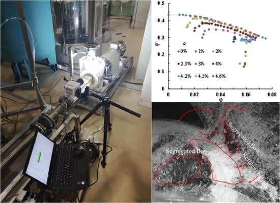
An open-type test loop was built to assess the pump performance and inner flow visualization measurement. As shown in Figure 1, the air injection system was able to provide 0.2 mm diameter bubbles using a specific compressor device (more details can be found in Si et al. [19,20]. The dehydrated air flow rate was measured and controlled by micro-electro-mechanical flow sensors systems (Bürkert 8107), which could supply a constant air mass flow rate in standard conditions value (25 °C, 101,325 Pa). The air-water mixed flow was sucked to the pump inlet, went through the flow passage, and reached the upstream open-type tank by using the valve to regulate the flow rate. The open tank allows air bubbles to be separated from the water rarely entering the closed-type tank (downstream tank). Flow rate of the pure water obtained after the second separation was measured by an electromagnetic flowmeter set between the separator and the mixer. Pump performance, such as head and global efficiency values, were obtained following ISO 9906:2012 [21].
Static pressure sensors, located at the pump inlet and outlet together with the torque meter, measured the pressure difference and torque information to calculate the pump head and efficiency following Equation (1) and Equation (2). All data acquisition and operating condition adjustments works were performed by the developed LabView program and an NI USB-6343 data acquisition card. αi defined by Equation (3) at the pump inlet was always kept constant and the proportional valve was adjusted to increase the pure water flow rate during each test procedure in order to have an overall performance curve for different values of αi. The open-type tank could be moved up and down to keep the pump inlet pressure constant to achieve the same inlet bubble diameter. The rotational speed of the pump was controlled by a frequency converter to maintain stability. Measurement uncertainties were evaluated as 1.2% error on the pump head, 2.4% on hydraulic efficiency, 0.1% on rotational speed, and 0.2% on αi.
A hydraulic model of a single-stage, single-suction, low-specific-speed, horizontal transparent centrifugal pump was used for the experiment. The flow rate of the pump model Qd was 25 m3/h, design head was 8.5 m, and the design rotational speed was 1450 r/min. Other corresponding main geometrical and flow parameters of the pump are shown in the last row of Table 1. Three-dimensional design impeller matching with a vaneless spiral volute was used to achieve a better pump performance. In order to improve the photographic accuracy, an unshroud impeller and a rectangular cross section volute passage were used together with the flat casing surface. The gap between the pump body and the blade tip was 0.5 mm. The outer surface of the inlet and outlet pipes was made into a square shape for observing the possible inner flow details. The experimental scene and pump model are shown in Figure 2.
3. Pump Performance Changes under Air-Water Two-Phase Flow
Each performance test was carried out using a small flow rate to a large flow rate while maintaining a constant inlet air void fraction (αi). Then, similar procedures were used to obtain the overall pump performance curves under different αi by increasing the air content. In order to evaluate the pump handling ability of air content, regardless of rotational speed, all performance parameters were dimensionless.
3.1. Overall Pump Performance at Two Different Rotational Speeds
Figure 3 and Figure 4, respectively, show the overall pump head coefficient ψ (Figure 3a,b) and global efficiency η (Figure 4a,b) versus the flow coefficient φ for two rotational speeds. The values of the two rotational speeds (1450 r/min and 1000 r/min) were chosen to verify the affinity laws. The consequences of increasing the values of αi on pump performance were that both head and efficiency degraded for both of the two rotational speed. Low flow rate was more sensitive to air content. The degradation slope increased with the decreasing flow rate coefficient when αi increased. The pump performance degradation at 1000 r/min was worse compared to 1450 r/min, which means that the affinity laws for the pump performance under a higher void of gas-liquid two-phase flow was no longer valid. This result is quite well-known since rotational speed is an important factor that allows the pump to work better when handling two-phase flow.
Theoretical head coefficients ψth are given in Figure 5 for both rotational speeds. Both images show the same theoretical head coefficient change for one-phase flow conditions (only water). However, global efficiency decreased for the lowest rotational speed because of a low Reynolds number (based on impeller outlet speed and radius) that may reach a limiting value of 105 for flow rates below 70% of nominal conditions. A unique curve was obtained for all inlet void fraction values up to 5% for 1450 r/min and 4% for 1000 r/min. Explanation of such an important result can be found in Si et al. [19,20]. These values also corresponded to severe pump head degradation that can be observed for a flow coefficient range value between φ = 0.055 and φ = 0.065.
3.2. Chnages in Pump Performance Degradation
3.2.1. Change in Water Flow Rate and Head Coefficient with Increased αi
Figure 6 shows how the flow rate was modified when inlet void fraction increased with an impeller rotating speed of 1450 m/min. Depending on the initial water flow rate (single water phase), the flow rate decreased. This feature was more pronounced under higher flow rate coefficients. The curve was constant until the αi was less than 3% when it started to drop sharply. This can also be observed for the pump head coefficient in Figure 7.
A more interesting analysis was performed using the dimensionless flow coefficient degradation ratio Φ*tp, defined as φtp/φ0 and shown in Figure 8, for the two different rotational speeds. Some slight modifications of the curve slope can be observed for different inlet void fractions depending on the initial flow rate conditions. Two distinct zones can be observed: the first one corresponds to αi between 0% and 4% for n = 1450 r/min and from 0% to 3% for n = 1000 r/min. The smaller the initial flow rate, the smaller the flow rate degradation for both rotational speeds. For higher values of the inlet void fraction (second zone), the slope is much important and a sharp decrease in the liquid flow rate can be observed. This decrease is less pronounced when the initial flow rate is big, which is consistent with the conclusion reached by several authors like Murakami et al. [2] and Minemura et al. [4]. A liquid flow degradation of 10% was obtained at αi = 3.5% for the lowest flow rate at 1000 r/min (Figure 8b), whereas this amount progressively reached 5% for the design flow coefficient at 1450 r/min (Figure 8a). The pump started to be quite unstable for a flow coefficient of 0.08 and around αi = 7% at 1450 r/min. When the rotational speed was lower, the same behavior could be found with a more limiting value of the maximum allowable inlet void fraction due to the reduced rotational speed.
3.2.2. Changes in Theoretical Pump Degradation for Two Different Flow Rates
Equivalent slope modification can be observed using the so-called “two-phase head coefficient ratio” ψ*tp. This parameter is very often used to characterize pump degradation level. It is defined as the actual two-phase head coefficient ψtp divided by the head coefficient ψ0 obtained from only pure water, namely ψ*tp = ψtp/ψ0. It is represented in Figure 9a for both rotational speeds and for the flow coefficient value of φ = 0.06, already referred to in the previous section. Figure 9b gives the corresponding changes for a lower flow coefficient φ = 0.04. Each curve exhibits quite a sharp degradation at a high inlet void fraction depending on the rotational speed. In Figure 9a, one can observe two different slope modifications. The first one occurs between inlet void fractions from 2.5% to 3%. The second one corresponds to the sharp performance degradation, which leads to the pump shut-off conditions. This was related to the visualization patterns and is discussed in the last section of the paper.
According to the assumptions proposed by Murakami et al. [2], Equation (4) is used to describe performance degradation factor ψ*tp versus inlet void fraction (all assumptions and development can be found in [2]). Ci is constant and equal to 0 for the present case. The value of k depends on the number of blades. Correlation proposed by Murakami leads to k = 2 and 3 for six blades:
For small gas-to-liquid value ratios (less than 10%), Equation (4) can be approximated as:
Because it assumes homogenous flow conditions, the curve corresponding to Equation (5) agrees well with the experimental results for 1450 r/min up to an inlet void fraction of 4%. For 1000 r/min, the flow velocity at the inlet pipe was small enough to reach churn flow conditions, as already pointed out by Si et al. [19], so that the equations could not well predict the experimental degradation factors.
A relationship between the flow coefficient degradation ratio Φ*tp and head degradation ratio ψ*tp could also be used, assuming affinity laws hold true, which leads to Equation (6):
Using the results shown in Figure 7, the corresponding curves are plotted in Figure 9. Using Equation (5), a comparison between experimental head degradation ratio and the corresponding flow degradation ratio looks to be in rather good agreement only for high rotational speed. This explains why several authors found that the affinity law can be applied for inlet void fraction values lower than 6% to 7% (Matsuchita et al. [22]). However, the curve obtained using Equation (6) gave lower values compared with the experimental ones for n = 1450 r/min. This clearly means that a rapid decrease in the liquid flow rate does not always correspond to a high head degradation rate, at least for low values of inlet void fractions. Combined analysis of liquid flow rate and head modifications should be performed, looking at several pump impeller design parameters, in order to get a better understanding of this relationship. In particular, more attention should be paid to incidence angle modifications at the inlet blade leading edge because the liquid flow rate decreases with increasing void fraction. And non-design flow rate conditions are affected by it.
Normally, the variation in pump performance curves is closely related to, and always represents, internal flow behavior. A general description of the pump head-drop phenomenon due to cavitation multiphase flow was established through a study of local and global flow fields by Li et al. [23]. So, visualization testing for integrity flow detail needs to be carried out and cross analyzed to physically understand pump performance degradation characteristic under two-phase flow conditions.
4. Physics of Flow Pattern Inside the Impeller and RSI Area
A Phantom VEO 710S type high-speed camera in conjunction with ultra-bright LED lights were used for capturing the flow characteristics of the air-water two-phase flow. These visualizations were performed for 1000 r/min because the acquisition procedure does not require a trigger with higher impeller rotational speed. Flow in a whole blade passage of impeller and near volute tongue area (RSI region) was observed as much as possible. The chosen frame rate was 8000 fps, the corresponding image resolution was 1024 × 800, and the exposure time was 30 μs. This allowed for the acquisition of more data in the passage between two blades and a better evaluation of the mean bubble diameter when a homogenous flow pattern was found (bubble diameter is increasing with the decrease in rotational speed because of lower overall mean and local pressure gradients). However, maximum inlet air void fraction cannot exceed 4% to 5%, as already explained in the previous section.
4.1. Flow Visualization Results under Different Inlet Air Void Fraction
The corresponding images are given in Figure 10 and Figure 11 for the two different initial flow rate coefficients and a given instantaneous position of the impeller blade. It can be seen that isolated bubbles exist at very low inlet void fractions up to 0.5% for all cases. Bubble diameter increases when αi increases and the flow remains as a bubbly flow regime up to 3% inside the impeller passage. This has been already found by Shao et al. [14], but the amount of bubbles was more important for the present case. In the volute section after the tongue, a bubbly flow situation could be observed for all void fractions.
Three-dimensional flow structures were observed using the visualization movies, similar to that in Figure 12. Strong secondary flows, starting from the inlet impeller hub region, move to suction the sider blade and interact with the tip leakage flow that develops on the shroud-forming vortex structures with opposite direction. This forced bubbles to accumulate near the suction side, close to the impeller outlet section. When αi reaches a value of 1%, the flow pattern looks better for the lower flow rate with a lesser bubble amount. This corresponds to a smaller reduction in the flow coefficient ratio that was been experimentally observed in Figure 8b compared with Figure 8a. Up to 2% of αi, the head degradation ratio followed the suggested homogeneous model proposed by Murakami et al. [2]. The curve fit the model up to 4% for n = 1450 r/min (see Figure 9a) and 2% (see Figure 9b). This can be related to the flow pattern observed in Figure 10c and Figure 11c for both rotational speeds. When αi = 3%, the flow pattern looked almost the same, but with less accumulation when rotational speed was high. The head degradation ratio was the same for both flow coefficients, but did not follow the homogeneous flow model any more.
Three-dimensional effects were more pronounced when the inlet void fraction was increased up to 3%; local relative flow velocity decreased, drag increased because of larger bubble diameters, and leakage remained important since the rotational speed remained the same. This led to an observed strong air accumulation (Figure 11e), which reached the whole impeller passage close to the shroud when αi = 4%. When αi = 4.2%, the flow pattern suddenly changed, as shown in Figure 11f. A segregated pattern was detected near the volute tongue with a clear separation of gas accumulation near the impeller outlet section, covering the whole space between the impeller outlet throat and its outlet radius. Fewer bubbles remained close to the shroud suction side due to the leakage flow (due to the axial gap between the open impeller shroud and the casing) and a clear transparent liquid zone was detected inside the impeller passage with few isolated bubbles. This zone was blocked by the air accumulation. It was experimentally observed that, for increasing values of αi, and after a few seconds of operation, the pump could no longer provide sufficient head and shut down.
Exactly the same flow patterns can be seen in the next photo sets (Figure 10) for a lower flow rate, but for a reduced value of αi. The flow pattern was similar for αi = 3.5%, as seen in Figure 10f, when compared with the pattern for αi = 4.2% and the higher flow rate. This flow pattern looked different compared to what is usually observed. For the present case, strong blockage to liquid flow was not located close to the first 20% of the impeller passage (as it is generally), but close to the end part of it due to the RSI effect. For better understand this effect, it has to be relate to the two previously described different degradation slopes that were detected. The first slope corresponded to a slight slope modification that occurred just before αi = 3%, which corresponded to a local blockage effect at the impeller inlet section, as already observed by Murakami and Minemura [1]. The second slope modification, which was quite larger, was located at the impeller outlet and was responsible for pump shut off at αi = 4.2%.
An additional phenomenon was detected in the outlet region of the volute tongue. Some bubbles that flowed at low velocities returned back to the impeller and the volute. This happened for all inlet void fraction values but was more pronounced when the mean bubble diameter increased. This effect is related to the increasing angle of attack at the volute tongue inlet section, which induces a strong separation on the upper part of the volute and lower pressure areas inside the initial part of the volute. For two-phase flow conditions, new volute designs should be tested in order to adapt its geometry to lower flow rate conditions compared with classical single-flow designs.
4.2. Unsteady Characteristics of the Flow Structure
The last set of images (Figure 12a–d) presents the instantaneous flow patterns for four different impeller blade positions, just before pump shut-off conditions were reached, where T is the time period of the impeller tips passing through the tongue region. Figure 12b corresponds to the same impeller blade position that is shown in Figure 10 and Figure 11 so that Figure 12b is equivalent to Figure 11b. Looking first at Figure 10 and Figure 11, it is obvious that the flow pattern looks a little different because these conditions were quite unsteady. The four instantaneous images show how strong the reverse flow was near the tip gap impeller shroud. Both segregate flow and water structures were simultaneously transported in the tangential direction (due to the impeller rotation) and in the inward radial direction due to the strong reverse flow occurring in the shroud gap region. As a consequence, three-dimensional separated flow vortices were observed up to the pump inlet location. This two-phase flow pattern of migration is believed to be the pump surge shut-off starting point.
5. Conclusions
Overall pump performance was measured for two different rotational speeds and several inlet void fractions up to pump shut-off conditions. Pump overall performance modifications were analyzed using both head and liquid flow rate changes with increasing values of the inlet void fraction, in conjunction with visualization studies performed near the volute tongue area. Main conclusions are presented here:
(1) Comparisons between the measured head degradation and the homogeneous model assumptions show that the pump head degradation can only be estimated for low inlet void fractions up to 4% for n =1450 r/min and 2.5% for n = 1000 r/min under an initial flow coefficient close to the smaller one.
(2) The maximum admissible inlet void fraction values are 7% and 4.5% for 1450 r/min and 1000 r/min, respectively, for the highest flow coefficient. Liquid flow modification does not follow head modification as described by affinity laws, which are mainly only valid for homogeneous bubbly flow regimes. For the lower flow coefficient (0.5 Qd), the same trend is observed but with a decrease in the maximum admissible inlet void fraction, i.e., 4.2% and 3% for n = 1450 r/min and n = 1000 r/min, respectively.
(3) With increasing inlet void fractions and decreasing flow rates, the bubbles increase in size and tend to agglomerate near the impeller suction side shroud at mid-chord and close to the pressure side close to the impeller outlet plane. The starting point of pump break down is related to a strong inward reverse flow that occurs in the vicinity of the shroud gap of the impeller and volute tongue area.
(4) Bubbly flow regime can be found inside the volute regardless of the flow rate and the inlet air void fraction up to the pump break down point.
Author Contributions
Investigation, writing—review and editing, Q.S. and G.B.; data curation, Q.C. and H.Z.; methodology—funding acquisition, S.Y.; validation, J.Z.; formal analysis, G.B.
Funding
This research was funded by the National Key R&D Program of China (2018YFC0810500), National Natural Foundation of China (51976079, 51779107), and Senior Talent Foundation of Jiangsu University: 15JDG048.
Acknowledgments
The authors gratefully acknowledge the financial support of the National Key Research and Development Program of China, National Natural Foundation of China, Training Project for Young Core Teacher of Jiangsu University, and Senior Talent Foundation of Jiangsu University.
Conflicts of Interest
The authors declare no conflict of interest.
Nomenclature
| b | impeller blade width |
| D | diameter |
| H | pump head |
| LVF | local void fraction |
| M | shaft torque |
| n | rotational speed |
| p | local static pressure |
| P | shaft power |
| Q | volume water flow rate |
| R | radius |
| Re,imp | impeller Reynolds number, |
| t | time |
| T | time period |
| u | circular velocity |
| v | absolute velocity |
| z | height level |
| Z | impeller blade number |
Greek Symbols
| α | inlet air void fraction |
| η | global efficiency of the pump, |
| v | water kinematic viscosity |
| φ | flow coefficient, |
| ρ | density of fluid mixture, |
| ω | angular velocity |
| Ωs | specific speed, |
| ψ | Head coefficient, |
Subscripts
| B | bubble |
| d | design condition |
| g | gas |
| i | relative to inlet condition |
| imp | relative to impeller |
| l | liquid |
| tp | related to two-phase condition |
| th | related to two-phase condition |
| 0 | related to α equal zero |
| 1 | impeller pump inlet |
| 2 | impeller pump outlet |
| * | non dimensional value |
References
- Murakami, M.; Minemura, K. Effects of entrained air on the performance of a centrifugal pump: 1st report-performance and flow conditions. Bull. JSME 1974, 17, 1047–1055. [Google Scholar] [CrossRef]
- Murakami, M.; Minemura, K. Effects of entrained air on the performance of a centrifugal pump: 2nd report-effects of number of blades. Bull. JSME 1974, 17, 1286–1295. [Google Scholar] [CrossRef]
- Minemura, K.; Uchiyama, T. Prediction of pump performance under air-water two-phase flow based on a bubbly flow model. J. Fluids Eng. 1993, 115, 781–783. [Google Scholar] [CrossRef]
- Minemura, K.; Uchiyama, T.; Shoda, S.; Egashira, K. Prediction of air-water two-phase flow performance of a centrifugal pump based on one-dimensional two-fluid model. J. Fluids Eng. 1998, 120, 327–334. [Google Scholar] [CrossRef]
- Noghrehkar, G.R.; Kawaji, M.; Chan, A.M.C.; Nakamura, H.; Kukita, Y. Investigation of centrifugal pump performance under two-phase flow conditions. J. Fluids Eng. 1995, 117, 129–137. [Google Scholar] [CrossRef]
- Jiang, Q.; Heng, Y.; Liu, X.; Zhang, W.; Bois, G.; Si, Q. A review on design considerations of centrifugal pump capability for handling inlet gas-liquid two-phase flows. Energies 2019, 12, 1078. [Google Scholar] [CrossRef]
- Barrios, L. Visualization of Multiphase Performance Inside an Electrical Submersible Pump. Ph.D. Thesis, The University of Tulsa, Tulsa, OK, USA, 2007. [Google Scholar]
- Zhu, J.J.; Zhang, H.Q. Numerical study on electrical submersible pump two-phase performance and bubble-size modeling. SPE Prod. Oper. 2017, 32, 267–278. [Google Scholar] [CrossRef]
- Zhu, J.J.; Zhang, H.Q. A review of experiments and modeling of gas-liquid flow in electrical submersible pumps. Energies 2018, 11, 180. [Google Scholar]
- Sato, S.; Furukawa, A.; Takamatsu, Y. Air-water two-phase flow performance of centrifugal pump impellers with various blade angles. JSME Int. J. Ser. B 1996, 39, 223–229. [Google Scholar] [CrossRef]
- Stel, H.; Ofuchi, E.; Sabino, R.; Ancajima, F.; Bertoldi, D.; Marcelino, N.; Morales, R. Investigation of the motion of bubbles in a centrifugal pump impeller. J. Fluids Eng. 2019, 141, 031203. [Google Scholar] [CrossRef]
- Mansour, M.; Wunderlich, B.; Thévenin, D. Experimental study of two-phase air/water flow in a centrifugal pump working with a closed or semi-open impeller. In Proceedings of the ASME Turbo Expo 2018: Turbomachinery Technical Conference and Exposition, Oslo, Norway, 11–15 June 2018. [Google Scholar]
- Verde, W.M.; Biazussi, J.L.; Sassim, N.A.; Bannwart, A.C. Experimental study of gas-liquid two-phase flows patterns within centrifugal pumps impellers. Exp. Therm. Fluid Sci. 2017, 85, 37–51. [Google Scholar] [CrossRef]
- Shao, C.; Li, C.; Zhou, J. Experimental investigation of flow patterns and external performance of a centrifugal pump that transports gas-liquid two-phase mixtures. Int. J. Heat Fluid Flow 2018, 71, 460–469. [Google Scholar] [CrossRef]
- Schäfer, T.; Bieberle, A.; Neumann, M.; Hampel, U. Application of gamma-ray computed tomography for the analysis of gas holdup distributions in centrifugal pumps. Flow Meas. Instrum. 2015, 46, 262–267. [Google Scholar] [CrossRef]
- Neumann. M.; Schäfer. T.; Bieberle, A.; Hampel, U. An experimental study on the gas entrainment in horizontally and vertically installed centrifugal pumps. J. Fluids Eng. 2016, 138, 091301. [Google Scholar] [CrossRef]
- Furukawa, A.; Togoe, T.; Sato, S.; Takamatsu, Y. Fundamental studies on a tandem bladed impeller of gas/liquid two-phase flow centrifugal pump. JSME Int. J. Ser. B. 1989, 55, 1142–1146. [Google Scholar]
- Matsushita, N.; Furukawa, A.; Watanabe, S.; Okuma, K. Study on design of air-water two-phase flow centrifugal pump based on similarity law. Int. J. Fluid Mach. Syst. 2009, 2, 127–135. [Google Scholar] [CrossRef]
- Si, Q.; Bois, G.; Jiang, Q.; He, W.; Asad, A.; Yuan, S. Investigation on the handling ability of centrifugal pump under air-water two-phase inflow: Model and experimental validation. Energies 2018, 11, 3048. [Google Scholar] [CrossRef]
- Si, Q.; He, W.; Cui, Q.; Bois, G.; Yuan, S. Experimental and numerical studies on inner flow characteristics of centrifugal pump under air-water inflow. Int. J. Fluid Mach. Syst. 2019, 12, 31–38. [Google Scholar]
- ISO 9906: 2012. Rotodynamic pumps-Hydraulic performance acceptance tests—Grades 1, 2 and 3. Available online: https://max.book118.com/html/2017/0914/133901920.shtm (accessed on 31 May 2012).
- Matsushita, N.; Watanabe, S.; Okuma, K.; Hasui, T.; Furukawa, A. Similarity law of air-water two-phase flow performance of centrifugal pump. In Proceedings of the 5th Joint ASME/JSME Fluids Engineering Conference, San Diego, CA, USA, 30 July–2 August 2007; Volume 37469, pp. 915–920. [Google Scholar]
- Li, X.; Jiang, Z.; Zhu, Z.; Si, Q.; Li, Y. Entropy generation analysis for the cavitating head-drop characteristic of a centrifugal pump. Proc. Inst. Mech. Eng. Part C: J. Mech. Eng. Sci. 2018, 232, 4637–4646. [Google Scholar] [CrossRef]
Figure 1.
Experimental design of two-phase research on centrifugal pump.

Figure 2.
Views of the experimental set up and the transparent pump model. (a) Test scene and (b) drawing of the pump assembly dimensions (mm).
Figure 2.
Views of the experimental set up and the transparent pump model. (a) Test scene and (b) drawing of the pump assembly dimensions (mm).

Figure 3.
Pump head coefficients for two rotational speeds: (a) n = 1450 r/min and (b) n = 1000 r/min.
Figure 3.
Pump head coefficients for two rotational speeds: (a) n = 1450 r/min and (b) n = 1000 r/min.

Figure 4.
Pump efficiency for two rotational speed: (a) n = 1450 r/min and (b) n = 1000 r/min.

Figure 5.
Pump theoretical head coefficients for two rotational speed: (a) n= 1450 r/min and (b) n= 1000 r/min.
Figure 5.
Pump theoretical head coefficients for two rotational speed: (a) n= 1450 r/min and (b) n= 1000 r/min.

Figure 6.
Liquid flow rate change for different inlet void fraction and initial water flow rates.

Figure 7.
Head pump change for different inlet void fraction and initial water flow rates.

Figure 8.
Flow coefficient degradation ratio for two rotational speed: (a) n = 1450 r/min and (b) n = 1000 r/min.
Figure 8.
Flow coefficient degradation ratio for two rotational speed: (a) n = 1450 r/min and (b) n = 1000 r/min.

Figure 9.
Changes in theoretical pump degradation for two different flow rates: (a) φ = 0.06; (b) φ = 0.04.
Figure 9.
Changes in theoretical pump degradation for two different flow rates: (a) φ = 0.06; (b) φ = 0.04.

Figure 10.
Flow pattern under φ = 0.04 for different αi: (a) 0.7%; (b) 1%; (c) 2%; (d) 2.5%; (e) 3%; and (f) 3.5%, pump shut off condition.
Figure 10.
Flow pattern under φ = 0.04 for different αi: (a) 0.7%; (b) 1%; (c) 2%; (d) 2.5%; (e) 3%; and (f) 3.5%, pump shut off condition.

Figure 11.
Flow pattern under φ = 0.06 for different αi: (a) 0.5%; (b) 1%; (c) 2%; (d) 3%; (e) 4%; (f) 4.2%, pump shut off condition.
Figure 11.
Flow pattern under φ = 0.06 for different αi: (a) 0.5%; (b) 1%; (c) 2%; (d) 3%; (e) 4%; (f) 4.2%, pump shut off condition.

Figure 12.
Instantaneous flow pattern for φ = 0.06 at αi = 4.2% at different time: (a) t0; (b) t0 + T/4; (c) t0 + T/2; and (d) t0 + 5T/6.
Figure 12.
Instantaneous flow pattern for φ = 0.06 at αi = 4.2% at different time: (a) t0; (b) t0 + T/4; (c) t0 + T/2; and (d) t0 + 5T/6.


Table 1.
List of pump parameters in reports on flow visualization.
| Reference | R2 (m) | R2/R1t(-) | n (r/min) | u2 (m/s) | u1 (m/s) | b2/R2 (-) | W1 (m/s) | Z (-) | β2 (°) | β1 (°) | Φd (-) |
|---|---|---|---|---|---|---|---|---|---|---|---|
| Murakami et al. [2] * | 0.112 | 2.24 | 1750 | 20.6 | 9.2 | 0.16 | 9.7 | 5 | 18.1 | 19.4 | 0.084 |
| Sato et al. [10] ** | 0.125 | 2.083 | 1100 | 14.4 | 6.9 | 0.144 | 7.34 | 8 | 25 | 20 | 0.069 |
| Stel et al. [11] *** | 0.1021 | 2.55 | 1150 | - | - | - | - | 8 | - | - | 0.09 |
| Mansour et al. [12] * | - | 2 | 650 | - | - | 0.15 | - | 6 | 24.7 | 19.5 | - |
| Verde et al. [13] *** | 0.0557 | 2.52 | 900 | 5.25 | 2.08 | 0.1077 | 3.0 | 7 | 46.8 | 45 | 0.098 |
| Shao et al. [14] ** | 0.125 | 3.125 | 1450 | 19.0 | 6.08 | 0.072 | 7.71 | - | 32 | 38 | 0.098 |
| Present pump * | 0.087 | 2.351 | 1000 | 9.11 | 3.87 | 0.138 | 8.175 | 6 | 30 | 28 | 0.08 |
* Open impellers with volute; ** Shrouded impeller with volute; *** Shrouded impeller with vane diffuser.
© 2019 by the authors. Licensee MDPI, Basel, Switzerland. This article is an open access article distributed under the terms and conditions of the Creative Commons Attribution (CC BY) license (http://creativecommons.org/licenses/by/4.0/).
Share and Cite
MDPI and ACS Style
Si, Q.; Zhang, H.; Bois, G.; Zhang, J.; Cui, Q.; Yuan, S. Experimental Investigations on the Inner Flow Behavior of Centrifugal Pumps under Inlet Air-Water Two-Phase Conditions. Energies 2019, 12, 4377. https://doi.org/10.3390/en12224377
AMA Style
Si Q, Zhang H, Bois G, Zhang J, Cui Q, Yuan S. Experimental Investigations on the Inner Flow Behavior of Centrifugal Pumps under Inlet Air-Water Two-Phase Conditions. Energies. 2019; 12(22):4377. https://doi.org/10.3390/en12224377
Chicago/Turabian StyleSi, Qiaorui, Haoyang Zhang, Gérard Bois, Jinfeng Zhang, Qianglei Cui, and Shouqi Yuan. 2019. "Experimental Investigations on the Inner Flow Behavior of Centrifugal Pumps under Inlet Air-Water Two-Phase Conditions" Energies 12, no. 22: 4377. https://doi.org/10.3390/en12224377
Note that from the first issue of 2016, this journal uses article numbers instead of page numbers. See further details here.