Solid-State Transformers in Locomotives Fed through AC Lines: A Review and Future Developments


Department of Electrical, Electronic, Tlc Engineering and Naval Architecture (DITEN), University of Genova, via all’Opera Pia 11a, 16145 Genova, Italy
*
Author to whom correspondence should be addressed.
Energies 2019, 12(24), 4711; https://doi.org/10.3390/en12244711
Submission received: 31 October 2019
/
Revised: 3 December 2019
/
Accepted: 6 December 2019
/
Published: 10 December 2019
(This article belongs to the Special Issue Energy Efficiency in Electric Motors, Drives, Power Converters and Related Systems)
Abstract
:One of the most important innovation expectation in railway electrical equipment is the replacement of the on-board transformer with a high power converter. Since the transformer operates at line-frequency (i.e., 50 Hz or 16 2/3 Hz), it represents a critical component from weight point of view and, moreover, it is characterized by quite poor efficiency. High power converters for this application are characterized by a medium frequency inductive coupling and are commonly referred as Power Electronic Transformers (PET), Medium Frequency Topologies or Solid-State Transformers (SST). Many studies were carried out and various prototypes were realized until now, however, the realization of such a system has some difficulties, mainly related to the high input voltage (i.e., 25 kV for 50 Hz lines and 15 kV for 16 2/3 Hz lines) and the limited performance of available power electronic switches. The aim of this study is to present a survey on the main solutions proposed in the technical literature and, analyzing pros and cons of these studies, to introduce new possible circuit topologies for this application.
1. Introduction
In last decades, many changes appeared in the railway sector thanks to the development of power electronics; as a matter of facts, nowadays railway vehicles are characterized by high specific power, high speed and high tractive effect. Thanks to these characteristics, they are able to manage both freight and passenger tasks with a single gear ratio.
The main problem in locomotives fed by AC lines is that an on-board transformer is needed, which main aims are:
- To supply the traction drive with a voltage furtherly lower than the voltage line (usually lower than 2 kV starting from 15 kV or 25 kV).
- To supply auxiliary services.
- To supply the conditioning system, which is fed at 1500 V if the line frequency is 50 Hz and at 1000 V if the line frequency is 16 2/3 Hz.
- To ensure galvanic insulation between the overhead line and vehicle equipment, mainly for safety reasons. Moreover, the transformer reduces also the effects of transient overvoltage, very frequent events in railway lines.
The transformer has to be sized according to line frequency, which can be 50 Hz or 16 2/3 Hz, and therefore is a critical component from the weight point of view, which has a drawback on rolling stock total weight; moreover, on-board transformers are characterized by quite low efficiency, which affects the traction chain overall efficiency. Many studies were carried out in order to reduce transformer weight, or to replace it with a power electronics converter. These studies, which were performed especially for high speed railways, where high AC voltage lines are used (i.e., 15 kV or 25 kV), aimed also to increase the traction chain efficiency. This last improvement was possible thanks to the lower losses obtainable with power electronics in comparison to traditional on-board transformers. Nevertheless, despite theoretical studies and prototypes, none of the proposed solutions seems to be capable of replacing the line-frequency transformer.
On-board transformers are single-phase, column-type and oil-immersed, designed for this specific application and therefore with very different characteristics in comparison to distribution transformers. Robustness is a required feature as well as high short-circuit impedance, which is a requirement to supply the four-quadrant converters connected to the transformer (Figure 1). Indeed, it has several low voltage secondaries which supply the converters. Other secondaries are dedicated to auxiliary services, heating, conditioning and, sometimes, to supply the L-C filter for harmonic suppression. One can observe that such type of machine is rather complex and bulky, therefore it is designed to reduce as much as possible size and weight, at the cost of low efficiency. In order to reduce transformer sizing, its rated power is generally lower that the traction power, since traction power is not constant and the transformer thermal constant is quite high. Winding current density is much higher than that in distribution machines and this aspect implies drawbacks in terms of losses. In addition, high losses imply the design of an effective cooling system, with forced-oil circulation and oil-air heat exchanger, is needed. Analogously, the core is designed for induction maximum exploitation, in order to minimize iron weight. However, transformer sizing is obviously related to the machine rated power and to the overhead line voltage frequency; for this reason, a 16 2/3 Hz transformer is heavier than a 50 Hz one, for same rated power. Considering a 6 MVA transformer, which is the typical transformer sizing of a modern locomotive, power density is about 0.55 kVA/kg for a 16 2/3 Hz machine and about 0.63 kVA/kg for a 50 Hz machine. Transformer weight is about 30% of locomotive weight and, since it is designed to minimize volume and mass, its efficiency is around 90% for 16 2/3 Hz machines [1,2,3,4]. For all these considerations, one can understand how transformer sizing is a critical task, especially for high speed trains and light locomotives, where the electrical equipment is generally installed in the underframe and the available space is limited, especially regarding components height, since the aim is to maximize the space available for passengers. In this scenario, it can be necessary to size the transformer taking into account the instantaneous required power, evaluated thanks to simulations which consider route characteristic (i.e., slopes and vehicle speed).
Starting from the end of ’70s, when the first three-phase fed locomotives came out, many studies were carried out to reduce transformer weight, volume and to increase its efficiency. Many solutions were proposed: transformer with high-temperature superconductive windings [5,6], transformer-less traction drives, with the traction chain directly fed by the overhead HV-line [7,8,9,10,11] and, the most promising, different solutions based on one or more medium frequency transformers with the opportune power electronic converters, from which the name Power Electronic Transformer (PET) [12,13,14,15,16,17,18,19,20,21,22,23,24,25,26,27,28,29,30,31,32,33,34,35,36] or other similar denominations. The interest in PET started in the early 2000s [12,13], continued in years 2007–2009 [14,15,16] and recorded a significant increase in last ten years. Indeed, from 2010 to 2016, a large number of technical papers have been published on this topic [17,18,19,20,21,22,23,24,25,26,27] and in last three years the interest has further increased [28,29,30,31,32,33,34,35,36]. PET solutions for railway rolling stock are conceptually analogous to Solid State Transformer (SST) used in grid applications [37,38,39,40,41,42,43]. These solutions should reduce transformer sizing preserving the galvanic insulation and the voltage matching function. The PET solutions aim to replicate, for high power and high voltage levels, architectures and structures which were already exploited and used for different low and medium power applications. In addition, the electronic transformer is not only a topic of great interest for railway traction, but also for electricity distribution, renewables, industrial applications and automotive sector [44]. In this applications the denomination Solid State Transformer (SST) is usually used. However, in this article, only railway application is taken into account, analyzing the features and constraints needed in this sector. The objectives of the PET should be reaching 1 kVA/kg specific power, in order to allow PET installation in the underframe or on the roof of high speed trains; moreover, an efficiency increase of about 2–5% is desirable. Indeed, even if the CO2 emissions associated to railways in the world are just 4.2% of the emissions associated to transports, the global high-speed train lines increase every year of about 8%. Therefore, the train efficiency issue will become of prior importance in next decades [45]. Annual CO2 world emissions are about 336 million tonnes, so an increase of just 1% in rolling stock efficiency would lead to a reduction of about 3.4 million tonnes of CO2 per year. In addition to the efficiency challenge, the potential reduction of weight, achievable with the use of PET technology, would allow, for the same rolling stock, to transport more passengers or freight.
It is interesting to observe that transformer weight problem is much critical in multiple unit train, generally used for high speed applications. As a matter of facts, in a traditional train, the weight of the locomotive has to be significantly higher than the weight of carriages, in order to increase the tractive force. In such scenario, the on-board transformer contributes to locomotive weight and therefore the reduction of weight is not the key factor for the introduction of PET technology.
Despite the above mentioned expected benefits, PET has some limits and problems which are hard to get around. Primarily, reliability, availability and maintenance costs play a very significant role in establishing the commercial success in the field of transport vehicles field [46]; this is particularly significant for PET, since it involves a large number of components: power switches, gate drivers, passive components, electronic components for control and monitoring, insulation shields and an adequate cooling system.
The aim of this article is to provide a survey on the main conversion architectures proposed in the last years, particularly focusing on the solution tested with large scale prototypes. After this first review, a possible future solution, exploiting Modular Multilevel Converter (MMC) is analyzed. In particular, simulation results, demonstrating the necessity of soft-switching modules for MMC application in railway rolling stock, are shown.
2. Power Electronic Transformer (PET)
The powertrain principle scheme of a typical modern railway vehicle is reported in Figure 1 and it is composed by the following components:
- Line-frequency transformer.
- AC/DC bidirectional single-phase rectifier (Four Quadrant Converter, 4QC).
- L-C resonant filter.
- DC-link.
- Inverter.
- Motor (which can be either an Induction Motor, IM, or a Permanent Magnet Synchronous Motor, PMSM).
The primary winding of the transformer is connected to the catenary voltage and usually there are several secondary windings. For example, in a modern Bo’Bo’ locomotive (4-axles, 2-bogies, 4-motors), four secondary windings are used to supply the 4QCs, as reported in Figure 2. Secondary output voltage is about 1–1.6 kV and therefore the DC-link has a voltage of about 2.4–2.8 kV. The DC-link resonant filter is tuned at twice the line frequency. One of the main functions of the 4QC is to make the rolling stock working at unit power factor, with obvious advantages on fixed installation sizing.
The drive concept is to be modular, for redundancy reason. In the Bo’Bo’ locomotive in Figure 2, for example, two identical semi-drives are used, one for each bogie. Minor variants can regard the number of secondary windings, DC-links, inverters, motors of Active Front Ends (AFEs) and AFEs mutual connections. The number of components depends on vehicle power, number of motors, desired degree of redundancy or on other constrains. Railway operators nowadays prefer multisystem traction vehicles, i.e., vehicles that can operate with different line voltages. This feature is important in order to use trains in international traffic and because there are different electrification systems, sometimes also in the same country (e.g., different voltages for traditional trains and high-speed trains).
As a matter of fact, in Europe there are four prevalent feeding systems:
- AC, 25 kV, 50 Hz.
- AC, 15 kV, 16 2/3 Hz.
- DC, 1.5 Kv.
- DC, 3 kV.
In multisystem vehicles, electrical equipment is easy to reconfigure. AFEs for AC feeding can work as choppers for DC supply; the transformer can be designed and sized to work both at 25 kV–50 Hz and 15 kV–16 2/3 Hz varying winding turns with taps; for DC feeding the secondary windings can be series connected and used as inductance input filter. Therefore, interoperability is a key feature that must be taken into account while considering PET technology.
A PET is basically an AC/DC conversion system with a medium frequency transformer, where the AC input is the line voltage and the DC output is a voltage of about 1–3 kV. Since the PET includes an AC/DC conversion stage, PET features have to be compared with on-board transformer plus 4QCs. The various topologies proposed until know can be divided in two main categories, depending on the input conversion stage:
- AC/AC input converter.
- AC/DC input converter.
The principle scheme of the first type of conversion chain in shown in Figure 3. This structure is assembled with the following components:
- Input inductance (between the overhead line and the 1st stage).
- AC/AC (1st stage).
- Medium frequency transformer.
- AC/DC (2nd stage).
After the above mentioned components, there is the traditional traction drive: DC-link filter, inverter and motor. The 1st stage aim is to increase the frequency from the line frequency to a medium frequency (several hundreds or several thousands of Hz); the medium frequency output is a square wave voltage (s.w.), in order to minimize transformer sizing and therefore the 2nd stage input is a square wave too.
The principle scheme of the second type of conversion chain in shown in Figure 4. This structure is made with the following components:
- Input inductance (between the overhead line and the 1st stage).
- AC/DC (1st stage).
- DC filter.
- DC/AC (2nd stage).
- Medium frequency transformer.
- AC/DC (3rd stage).
Compared to the first type of PET, which involves two conversion stages, in the second type, three conversion stages are involved, plus, obviously, the traction drive, which is the same in both cases. For this reason, authors will refer to the first type as 2-Conversion Stages PET (2CS PET) and to the second type as 3-Conversion Stages PET (3CS PET).
In both cases a multilevel converter is needed for the 1st stage, since the input voltage (15 kV or/and 25 kV) is too high to be tolerated by available power switches in conventional two-level converters. Since the transformer has to work at sufficiently high frequency, in order to obtain a significant weight reduction, soft-switching is mandatory for the converter that supplies the transformer. Whatever the soft-switching circuit is, an extremely high number of semiconductor devices and gate-drivers is needed, with obvious problems in terms of costs, reliability, efficiency, cooling and insulation. This is the main reason why, despite the efforts in studies and prototypes, PET has not found a practical implementation yet. It is quite possible that PET will find an easy success with the availability of switches with two-three times greater rating voltage than that of semiconductor devices available today (6.5 kV) and able to operate at frequencies of some tens of kHz.
At this point, it is necessary to point out the main targets that have to be achieved with the PET technology:
- Weight reduction (at least 50%, or, analogously, increasing the specific power at least to 1 kVA/kg).
- Volume reduction (at least from 30% to 50% less than line frequency transformer).
- Efficiency increase (at least 2–5%).
- Capability of supplying traction loads, auxiliary services, air conditioning, heating, etc.
- Capability of reconfiguration for multisystem power supply.
- Capability of delivering a stabilized DC-link voltage, independently from line voltage variations.
- Reversibility of the system to allow electrical braking with recovery on the supply line.
- High reliability.
- Simple cooling of semiconductors and medium frequency transformer.
- Capability of reconfiguration in case of failure.
- Easily maintainable and repairable.
- Easily controllable.
- Absence of noise and vibrations.
- Robustness.
- Capability of working in a temperature wide range.
- Low cost.
Regarding efficiency increase, the PET includes two or three conversion stages, so the efficiency of the all chain should be greater than the efficiency of the low frequency transformer plus the 4QC. For this reason, the conversion stages and the medium-frequency transformer have to be particularly efficient, which in obviously difficult with such a complex structure and such a high number of components. The high number of components is of course in contrast also with the requirement of high reliability, even if this aspect can be mitigated thanks to a modular structure, which can be reconfigured in case of failure of a module.
The study of PET involves a widespread range of topics that require accurate investigations:
- Power electronics devices insulation (materials, shields, covers).
- Medium frequency, high power transformer.
- Development of power semiconductors specifically designed for soft-switching operation, with switching losses minimization at the expense of conduction losses, obtainable with particular treatments such as doping and irradiation [20].
- Gate driver powering when installed on system operating at medium voltage.
- Modular design of compact and lightweight building modules, Power Electronics Building Blocks (PEBB).
- Reliability of system with such a high number of semiconductor devices and gate drivers
- Strategies and hardware for control and diagnostics.
- Transient behavior in case of pantograph bouncing from the line (frequent event and lasting < 15 ms).
3. Review of Main Conversion Architectures
With the availability of 3.3 kV high-power IGBTs (Insular Gate Bipolar Transistor), many studies were carried out on railway traction at the end of the ’90s [10,11], proposing innovative architectures, modular and based on the use of high performance IGBTs. These studies consisted of a four quadrant multilevel converter in a cascade connection of H-bridges, as 1st stage to interface with the 15 kV, 16 2/3 Hz overhead line voltage. As 2nd and 3rd stage, a reversible DC/DC converter composed of a DC/AC with H-bridge, a medium frequency transformer and a AC/DC with H-bridge was proposed. It was hypothesized the use of a series-resonant circuit in the AC-link, in order to reach sufficiently high frequency for transformer operation. Further studies were carried out by the same researchers regarding an architecture which could work both at 15 kV, 16 2/3 Hz and 3 kV DC [69].
Regarding IGBT peak voltage and the required number of stages, it is necessary to observe that the maximum admitted voltage is 29 kV RMS for 25 kV/50 Hz systems and 18 kV RMS for 15 kV/16 2/3 Hz systems. Therefore, the required number of stages is reported in Table 1.
3.1. Alstom-SMA “eTransformer”
In 2003 Alstom LHB GmbH and SMA Regelsysteme GmbH presented a prototype called eTransformer [12]. The prototype is a three-stage converter (3SC). Its main feature are reported in Table 2, whereas its scheme is shown in Figure 5.
The HV input (1st and 2nd stages) consists of an input reactor and eight AC/AC s.w. (i.e., converter from AC to square wave, s.w.) conversion modules in cascade connection (multilevel concept). The 1st stage is a full H-bridge AC/DC whereas the 2nd stage is an half H-bridge DC/AC s.w. The primary of the transformer is fed with a resonant circuit (capacitor and leakage inductance of the transformer), which is tuned at 5 kHz. While there are eight modules for 1st and 2nd stage, there is only one H-bridge for the 3rd stage, which feeds the low voltage DC-link, equipped also with an LC filter. The 1st stage converter works in hard-switching, since its switching frequency can be relatively low, and it is equipped with 6.5 kV–400 A IGBTs. The 2nd stage converter works in soft switching, with a quasi-zero current switching (quasi-ZCS), and it is equipped with 3.3 kV IGBTs.
In case of fault of one of eight modules, the failed one can be bypassed and the operation can continue without any limitation on the power. Semiconductors and transformer are cooled with forced oil. This solution uses 52 IGBTs with the related gate-drivers, plus additional passive components and auxiliary items. Despite the number of semiconductors is about three times greater in comparison to a traditional line-frequency transformer solution, the eTransformer has the benefit of using a relatively low number of devices with respects to other PET solutions.
3.2. Bombardier Transportation “Medium Frequency Topology”
In 2007 Bombardier Transportation presented a laboratory prototype called “Medium Frequency Topology” [14], which exploits the principle shown in [10,11] and which is designed for 15 kV, 16 2/3 Hz. PET main features are reported in Table 3, whereas PET scheme is shown in Figure 6. Analogously to the eTransformer, it is a 3SC and it is made of eight identical modules cascade connected. Differently from eTransformer, where only one medium frequency transformer is used, in Medium Frequency Topology a transformer is used for each module and the outputs of the modules (LV DC-link) are parallel connected. The 1st stage is a AC/DC full H-bridge, the 2nd stage a full H-bridge DC/AC s.w. (differently from eTransformer that has an half-bridge) and the 3rd stage is again a full H-bridge AC s.w./DC. If one of the modules fails, the Medium Frequency Topology can work with a reduction of power of 1/8; indeed it uses 6.5 kV IGBTs for the 1st stage and therefore 7 modules are sufficient for 15 kV line voltage. The transformers are just 18 kg each and they have 1:1 winding ratio. The main disadvantage of this PET is that a great number of IGBTs, and of course of auxiliary devices, is needed. A reduction of number of components can be performed using half H-bridges, as shown in next solutions.
3.3. ABB First Converter Prototype
In 2007 ABB presented its first laboratory prototype [15], whose main features are reported in Table 4 and whose scheme is shown in Figure 7. Differently from the abovementioned PETs, this prototype is a 2SC. It uses all 3.3 kV, 400 A IGBTs in 16 modules, therefore double number of modules, compared to previous PETs, is needed since it uses 3.3 kV IGBTs. A medium frequency transformer with 1:1 ratio is used for each module. The transformer frequency is quite low (400 Hz), therefore it is not possible to exploit a significant transformer size reduction. For this reason, dimensions related to this solution are greater than those of a traditional architecture (line frequency transformer + 4QCs). Regarding the efficiency, even if at medium and high loads the efficiency of the prototype is 3% higher than that of a traditional transformer, at low loads the efficiency is even lower. In additional to these disadvantages, this prototype involves the use of 192 IGBTs. For these reasons it is outdated.
3.4. ABB Power Electronic Traction Transformer (PETT)
In 2012 ABB presented probably the most advanced prototype of PET, which is called Power Electronic Traction Transformer (PETT) [19,20,21,22,23,24], whose main features are reported in Table 5 and whose scheme is shown in Figure 8. The PETT is a 3SC, includes nine cascade connected modules, one for redundancy, and has a medium frequency transformer for each module. The 1st stage is a full H-bridge AC/DC which uses 6.5 kV–400 A IGBTs and which supplies the 3.6 kV DC-link; the 2nd stage is a half H-bridge DC/AC s.w. which uses again 6.5 kV–400 A IGBTs. Finally, the 3rd stage is a half H-bridge AC s.w./DC which uses 3.3 kV–800 A IGBTs. In the LLC resonant circuit, both the leakage inductance and magnetizing inductance participate at the resonance, whereas, in order to minimize weight and dimension, a ripple in the output voltage is accepted, so the LC filter is not necessary.
The specific power, related to rating and maximum power, is only 0.266 kVA/kg and 0.4 kVA/kg respectively, which is quite low. Even if the power density should be increased at least to 0.5–0.75 kVA/kg, the PETT is the first answer related to this technology and, moreover, the efficiency of 96% is significantly higher than a traditional line frequency transformer with 4QCs.
4. Bombardier and ABB AC-Link
In this section, Bombardier and ABB DC/DC converters (i.e., 2nd stage, medium frequency AC link and 3rd stage of Figure 6 and Figure 8) are analyzed in detail. Both converter, using full H-bridge or half H-bridge, are fully reversible, so they can perform regenerative braking. Bombardier uses a full H-bridge solution both for 2nd and 3rd stages, whereas ABB PETT uses a half H-bridge solution for both stages. ABB solution needs half semiconductor devices (4 IGBTs per module instead of 8) and half of related auxiliaries (gate-drivers, etc.). However, for the floating DC-links, four capacitors are necessary instead of the two capacitors of Bombardier solution, in order to create the central taps. Both solutions have pros and cons. From reliability point of view, the failure rate of an IGBT with related components is higher than the failure rate of a capacitor; however, DC-link capacitors are usually bulky and heavy, therefore ABB solution is not optimal from sizing point of view.
Bombardier uses a classical LC resonant circuit, where the inductance is the transformer leakage inductance; transformer magnetizing inductance is quite high and it is not exploited in this solution. The resonant frequency is:
where is the transformer leakage inductance and the capacitance of the AC link. The operating conditions depend on the ratio between the resonant frequency and the switching frequency [70,71].
ABB solution uses a more performant LLC resonant circuit, which exploit both the transformer leakage inductance and the magnetizing inductance . For this reason, the circuit has two different resonance frequencies:
Being, usually, it follows that LLC resonant circuit has many advantages compared to the LC circuit, which make this configuration particularly suitable for this application:
- Higher range of output voltage.
- Primary winding switching losses reduction in a wide range of operation, thanks to Zero-Voltage Switching (ZVS).
- Low circulating energy and Zero-Current Switching (ZCS) in secondary side rectifier diodes.
After this brief introduction on converter main features, the two structures are analyzed in detail in the following subsections.
4.1. Bombardier Converter
The LC full H-bridge used by Bombardier (Figure 6) allows, from a theoretical point of view, ZVS and ZCS of all active components, which make possible to reach relatively high switching frequencies, up to 10 kHz. Both for the input bridge and the output bridge, 6.5 kV IGBTs are used, even if experimental tests on prototypes were performed also with 3.3 kV and 4.5 kV IGBTs. The medium frequency transformer has a 1:1 ratio and therefore same size of IGBTs can be used both for primary and secondary size. The transformer has concentric windings, that guarantee optimal electric and magnetic field symmetry (which allows symmetric current in the devices), optimal insulation exploitation and low flux leakage. As further advantage, switching losses are minimized also in non-ZCS working operation. Switching frequency is chosen close to resonance frequency. Current and voltage sensors are not necessary for close-loop control, indeed open-loop control is used. IGBT commands of input and output bridge are synchronized, with a 50% duty cycle and additional blanking time. Therefore, on both windings there are square wave synchronized voltages. It is interesting to note that it could be sufficient to control the IGBTs of the input converter (2nd stage), since the output converter (3rd stage) works as a rectifier and the current flows in the diodes. However also 3rd stage IGBTs are commanded, in order to prevent malfunctioning and delays in case of regenerative braking; indeed, in this working condition, the 3rd stage IGBTs have to be commanded.
Even if the converter theoretically guarantees soft-switching (i.e., ZCS and/or ZVS), which allows negligible switching losses, one has to take into account the real behavior of the switches. Indeed high power IGBTs are optimized to work in hard-switching, therefore the physical structure is optimized to minimize conduction losses, rather than switching losses. This aspect implies that, in practical operation, soft-switching condition is partially respected: switching losses are produces and they depend on the behavior of the components during the transients. Converter optimization, and therefore efficiency optimization (which is evaluated around 97% on prototypes), can be therefore obtained with an accurate tuning between converter parameters and semiconductor features.
4.2. ABB Power Electronic Traction Transformer
ABB PETT (Figure 8) uses two half H-bridges for 2nd and 3rd stage and the LLC resonant circuit allows turn-on ZVS for 2nd stage IGBTs and ZCS turn-on for 3rd stage diodes; 2nd stage turn-off is quasi-ZCS and can be obtained with an opportune choice of component parameters and imposing a very low current during the turn-off (Iturn_off). This current is related to transformer magnetizing current and depends on transformer magnetizing inductance, on switching frequency and on DC-link voltage, but is independent from converter load. Therefore, this resonant scheme considers by default switching losses, caused by Iturn_off, which is different from zero (despite it is low and independent from the load) on the input half-bridge IGBTs. The turn-off losses are therefore constant and load-independent, but predominant in comparison to conduction losses; for this reason it is necessary to minimize them. Even if Iturn_off causes turn-off switching losses, it allows IGBT ZVS turn-on, therefore an excessive reduction of Iturn_off can cause undesired turn-on switching losses. Moreover, IGBT turn-off losses are related not only to Iturn_off, but they strongly depend also on IGBT dynamic characteristics. Moreover, turn-on ZVS condition is strongly related to dead time, which can be quite high, tens of microseconds, for high power IGBTs. From these considerations, one can notice that switching losses maximum reduction can be achieved with an accurate choice of converter parameters and through the optimization of semiconductor dynamic behavior, as observed before also for Bombardier converter.
In [20], an accurate description of an experimental test regarding the interaction between semiconductor properties and circuit properties is reported. The optimization of IGBT physical structure is investigated, with the redesigning of anodic structure, which has an effect on charge carriers in silicon thickness and can therefore modify the behavior during the switching, potentially improving switching phenomenon and reducing the losses. The aim of the study is to find a structure that could reduce switching losses at high switching frequency (higher than 1 kHz) but that could, at the same time, avoid conduction losses increase. Indeed, previous studies using electron irradiation show a reduction of switching losses but at the cost of conduction losses increase.
ABB studies have been performed on a 225 kW converter. The DC/DC converter has 3.6 kV input voltage and 1.5 kV output voltage; the 225 kW transformer has 2.4:1 winding ratio. On the input half-bridge 6.5 kV–400 A IGBTs are used, whereas 3.3 kV–800 A IGBTs are used for the output half-bridge. Switching frequency is 1.8 kHz, which is just under the resonance frequency of 2 kHz. With this choice of fs and f0, the relation between input and output voltage depends only on transformer winding ratio. For this reason, also this converter works in open loop.
5. A New Conversion Architecture for PET Application: Modular Multilevel Converter (MMC)
From the analysis of architectures and prototypes shown in the previous section, some considerations can be pinpointed at this stage:
- The research focuses mainly on new architectures. Other aspects like converter lay-out, converter on-board placement, cooling, converter management, failure modes etc., are neglected (except in ABB PETT, since a demonstrator was realized).
- The high number of requirements that a traction transformer should ensure is not always taken into account in the new conversion systems.
- The proposed topologies are inspired to solutions used in low power and low voltage applications.
- The medium frequency for the transformer is quite low, despite significantly higher than line frequency.
- All the solutions require a high number of semiconductor devices and of passive components. From this point of view, there are significant differences between the architectures but the high number of devices is a common feature.
- In some solutions, the total power is subdivided among various medium frequency transformers. This could be an advantage from a reliability point of view, but it implies problems related to dimensions, weight and layout (large number of electrical connections, of sensors, cooling connectors, etc.).
- All the solutions are extremely modular, in order to guarantee high reliability levels, even if with complex circuits and high number of devices.
- It is shown that soft-switching is necessary to increase the semiconductor maximum operating frequency, which is quite low. Indeed the optimal switching frequency for hard-switching operation of IGBTs used in railway rolling stock is about 600 Hz [72], which is too low for medium frequency transformer exploitation.
- In some studies, in particular in ABB PETT, the possibility of using IGBTs optimized for soft-switching operation is taken into account. The performance increase is obtained intervening in the device physical layout or with opportune treatments in the production process. The aim of switching losses reduction is indeed to increase the medium frequency value of the transformer.
None of the proposed architecture is really satisfying; the ABB PETT, despite an accurate study, an excellent engineering of the converter and the use of advanced techniques such as devices optimized for soft-switching working condition, is far from meeting volume and weight target.
The main limits and problems to resolve are:
- The high number of devices.
- The low frequency of the transformer.
- The use of modular and redundant structures (such as the use of various number of transformers and the use of three conversion stages). The complexity of modular and redundant structures is in contrast with the necessity of volumes reduction, since in addition to electrical connection, one has to take into account the insulation distance (since the line voltage is relatively high), the hydraulic connections for the cooling system, etc. The use of three stages instead of two stages is conceptually disadvantageous also from an efficiency point of view.
- The adaptation of schemes and circuits used in the low/medium power and low voltage may not be the optimal solution. It could be more opportune to base on schemes designed for high power—high voltage.
- The complexity of the converter involves high cost during the life cycle.
5.1. MMC Concept
A solution that appeared some years ago and that is opportune to analyze, integrates in the conversion chain a Modular Multilevel Converter (MMC). The MMC (also referred as M2C, M2C or M2LC) was presented for the first time in 2003 and is characterized by very high quality of modularity, flexibility, voltage and current waveforms [1,13,73,74,75,76]. More than a conversion scheme, the MMC is a concept of a family of converters, which can generate different types of conversion: AC/AC or DC/AC, single-phase or multiphase. The circuit structure is divided into phase modules (two or more), each of which is made of two arms, an upper one and a lower one, as it can be noticed from Figure 9. Conceptually, the scheme in Figure 9a is analogous to a two-level inverter, in which the MMC arms are the inverter switches plus the free-wheeling diodes. In the MMC, instead, each arm is made of a connection of submodules. Each submodule can be a half H-bridge or a full H-bridge, with a DC-link capacitor. The submodules are half-bridges for DC/AC conversion and full-bridges for the AC/AC conversion. The operating principle of a MMC is presented in [73].
Each arm of N submodules, if properly controlled, behaves like a variable voltage generator, in which the source is made of the series connection of the DC-link capacitors of the arm. Connecting in a proper way two or more phase modules, and realizing a suitable control, it is possible to obtain whatever type of conversion with whatever number of phases. The MMC control algorithm manages the power flow between input and output sources controlling at each switching period the stored energy in the DC-link capacitors.
It is necessary that at a certain instant, the stored energy is higher than a certain threshold and, moreover, there should be an equalization of the voltage between the different capacitors. Therefore, there should be an accurate control of the voltage on each capacitor and this implies the use of complex algorithms.
The general scheme of a railway rolling stock drive with the use of a MMC converter is shown in Figure 10 [13,74,75,76]. This structure uses a single medium frequency transformer with primary voltage of 13.5 kV and one or more secondary windings at 2.7 kV, each of which supplies a conventional traction drive (4QC-DC, filter, inverter and motor). The use of a single transformer is evaluated suitable since the construction of a single machine, sized for the locomotive full power and insulated for relatively high voltage (thus, with a bulky insulation), is simpler than that of various smaller transformers. Indeed, it implies a reduction in materials (especially the iron of the magnetic core) and therefore a reduction of dimensions, weight and costs.
In [13] a possible multisystem application is presented, highlighting how simply varying the number of active submodules for each arm and acting on the control, it is possible to easily pass from 15 kV–16.7 Hz to 25 kV–50 Hz. However, no experimental results related to such a type of converter are known in the technical literature.
On the contrary, the MMC concept attracts the attention in high-power and high-voltage applications [40,62,63,77,78,79]: electrical drives [80], HVDC [81,82,83,84,85], photovoltaic [86] and in stationary installations that supply the primary lines of German railways (i.e., from 110 kV–50 Hz three-phase to 110 kV–16.7 Hz single-phase).
The MMC has many interesting advantages compared to other structures:
- Conversion topology of proven validity, able to work at very high power and voltage (hundreds of kV and MW in HVDC applications).
- Highly modular, with identical and interchangeable submodules. The submodule includes 4 switches and a DC-link capacitor, which can assembled in a unique rack (Power Electronic Building Block—PEBB) that includes also the heat sink and the sensors. More submodules can be put side by side or on top of each, with a great exploitation of the available space.
- No need of low inductance connection between submodules.
- Only two stages, with benefits on the efficiency.
- Single medium frequency transformer.
- Flexible and intrinsically multisystem, thanks to the possibility of realizing different type of conversion just modifying the control.
- Perfectly reversible.
- Line current with low harmonic distortion.
- MMC allows different possibility of optimization, all of which obtainable just modifying the control but without intervention on hardware: switching losses reduction, line harmonics reduction, etc.
- Excellent static and dynamic behavior.
- No need of filter tuned at double line frequency: the converter can compensate the pulsation of the line power thanks to the energy stored in the submodules.
- Intrinsically fault tolerant.
- Simple interface with control electronic: gate-drivers can be supplied from the DC-link capacitor and the command signals are sent through fiber optic.
Besides these advantages, there are some critical aspects in the use of MMC in railway rolling stock:
- High number of components. Using 3.3 kV switches and 940 µF–1900 V capacitors, with 12 submodules per each of the four arms, 192 switches (IGBT plus diode) and 48 capacitors are needed [75,76]. Using 6.5 kV IGBTs, 7 submodules can be sufficient thus 112 switches and 28 capacitors can be used, which is still a high number of devices. To this number of devices, components of 4QC should be added, thus the MMC solution has more components than the other solutions.
- Since the MMC works in hard-switching, the medium frequency is quite low (from hundreds of Hz to about 2 kHz).
- The control logic is quite complex.
- From an efficiency point of view, the comparison should be between the MMC + medium frequency transformer + 4QC and line frequency transformer + 4QC. In order to be more efficient, medium frequency transformer and MMC efficiency should be in the range of 98–99%. There is no experience with such a high power (about 5 MW) medium frequency transformer to determine the efficiency and, even if the MMC is very efficient, the target could be difficult to reach.
Even if there are these critical aspects, the MMC concept is interesting to be investigated in railway application. This paper studies and analyzes the main problems, in order to find possible solutions.
5.2. Soft-Switching MMC: Description and Waveform Simulation
One of the main limitations in the use of MMC for railway application is connected to its switching frequency. In order to reduce transformer volume and weight, it should be necessary to have at least a frequency of 7–8 kHz and significant advantages will be obtained with a frequency of 10–20 kHz. Even if the MMC is quite refined and exploit optimally the switching frequency, the features of high power switches (some kV and hundreds of A) limits the MMC frequency at 1–2 kHz. In the first studies [13,76] the switching frequency was 4 kHz for the two-voltage version (18 submodules per arm), with a submodule medium frequency of 350 Hz and an output voltage switching at 2 kHz; 4 kHz switching frequency for the one-voltage version (12 submodules per arm), with an output voltage switching at 1 kHz.
The MMC is intrinsically hard-switching but, being composed by identical submodules, there could be the possibility of increasing the switching frequency using a soft-switching topology [42,54] in the H-bridge; the aim of the study is to investigate this aspect. One has to note that if the switching frequency of the single submodule increases, once the desired output frequency is fixed, the number of submodules can decrease, and therefore the number of devices.
Among the various soft-switching solutions, it is necessary to identify the most suitable architecture for the application in the MMC concept and, in particular, to the use in railway rolling stock. Typically, resonant circuits introduce some problems that have to be taken into account:
- Increase in voltage/current stresses on the main converter power components, which in some cases can be quite high, more than 2 p.u.
- Not safe soft-switching operation, i.e., soft-switching depending on load current and other constraints.
- Impact of the soft-switching circuit with the overall operation of the converter.
- Inadequacy or only partial adequacy to the PWM modulation.
The soft-switching solutions can be classified in three main families:
- Resonant switch: the resonant circuit is applied to each single switch.
- Resonant pole: the resonant circuit is applied to a branch of the module.
- Resonant link: the resonant circuit is applied to the DC-link of the module.
Since the MMC is itself a complex system, with a large number of components, the additional components used to obtain the soft-switching condition, should be as less as possible. For this reason only the resonant pole and the resonant link families are taken into account. Several topologies were examined in this study:
All the above mentioned soft-switching topologies are designed for three-phase inverters, however, the adaptation to a single phase H-bridge of the MMC is still quite easy. Among the above mentioned topologies, the most interesting to realize soft-switching submodules for the MMC converter seem to be the ARCP (resonant pole family) and the AQRDCL (resonant link family), which are reported in Figure 11. The other topologies seem to be unsuitable for the MMC application due to the high stress on devices, the dependence of soft-switching condition from the load or the impossibility of operating in PWM.
The ARCP seems to be particularly suitable for this application and has some interesting features:
- ZVS both in turn-on and turn-off of the main devices (T1, T2, T3, T4) and ZCS or at least quasi-ZCS of the auxiliary devices of the resonant circuit.
- Oversizing of main devices is not necessary since there are not overvoltages and overcurrents.
- The output voltage and current waveforms are about the same as in hard-switching under same operating conditions. The only different is that the slope of the output voltage steps are less steep.
- dv/dt and di/dt on the main devices are lower than in hard-switching.
- Possibility of operating at high switching frequencies, from 10 kHz to 30 kHz with low losses [13].
- The resonant inductor may be designed with a small size, since it is subjected to a limited current stress (indeed it conducts only during the switching transient).
- Auxiliary switches are involved by same inductor current and they work in ZCS.
- Low losses on resonant circuit passive components.
- Fully controllable resonant soft switching process.
- High overall efficiency.
- Possible operation in full PWM.
The AQRDCL is derived from the ARCP, but unlike the previous type, which is a resonant-pole, the AQRDCL is a resonant-link. While the ARCP needs two resonant circuit for each H-bridge, the AQRDCL uses a single circuit acting on the DC-link. Therefore, the AQRDCL needs less auxiliary components, but at the price of a more complex control and some more limitations. Moreover, it needs a clamp switch that has the task of disconnecting the DC-link from the source during the commutation intervals and which commutates at the switching frequency, therefore its losses could be not negligible. The AQRDCL control is more complex and it requires faster devices, indeed the timing sequence in device command requires a very short time, and it is therefore necessary to use a proper control to handle situations where a resonant cycle is triggered before the previous one is finished. For this reason, after a preliminary analysis, it seems that the AQRDCL is more suitable for lower power than ARCP, about hundreds of kW, but it is anyway a topology to be taken into account too.
In the ARCP the capacitive snubbers guarantee turn-off ZVS, whereas the resonant circuit (in which snubber capacitors act as resonant capacities) allows turn-on ZVS. The auxiliary switches work in quasi-ZCS both in turn-on and turn-off. Unlike other topologies, the resonant circuit is parallel connected to the main switch only around the switching transient; outside this short time, the resonant circuit is not involved by the load current. This is an advantage for the sizing of the resonant inductor, which should not sustain continuously the load current (therefore also its losses are low). Another advantage is that the behavior of the H-bridge is very similar to the one in hard-switching, since the resonant circuit is disconnected for the major time of the switching period. In other simplest topologies, resonant inductor is connected in series to the DC-link and it must therefore sustain the load current continuously.
Some simulation results, using the control strategy presented in [116], are shown in Figure 12. One can notice that devices are less subjected to dv/dt stress, but apart from this, output voltage and current waveform is quite similar to PMW modulation waveform.
In the AQRDCL, differently from the ARCP, there are not snubber capacitors, but a clamp switch (Sc-Dc) is necessary. During the switching, the commutation of the main switches, the turn-off of the clamp switch and the turn-on of the auxiliary switches, properly coordinated, occur. The consequence is the zeroing of the DC-link voltage for a short time, so that the switching of the main switches occur in ZVS both for turn-on and turn-off. At the end of the switching process, the resonant circuit is deactivated and the DC-link voltage grows at its value, since the clamp switch starts to conduce. Like in the ARCP, the auxiliary switches work in ZCS. Some simulation diagram of a single submodule, together with the output voltage of a 4-submodules for branch MMC are reported in Figure 13. Also in this case, one can notice that voltage waveform in quite similar to a MMC working in hard-switching.
5.3. Soft-Switching MMC: Losses Evaluation
In order to evaluate the benefits of soft-switching in the MMC, a model with two full H-bridges (one working in hard-switching and one working in soft-switching) with same rating and in same working points, is created in PSIM software (8.0.7, Powersim, Rockville, MD, USA) equipped with Thermal Module.
The DC-link capacitor voltage is set to 2500 V, the switching frequency to 6 kHz, the modulation index is set respectively to 0.25, 0.5 and 0.75, and the converter works on a R-L load with cosφ = 0.8, so the load currents are 77 A, 155 A and 230 A RMS, respectively, for the three modulation indexes. The output frequency is 450 Hz and the resonant frequency 70 kHz. IGBTs ABB 5SNA650J450300, 4500 V–650 A are used. Simulation losses in hard-switching configuration are reported in Table 6.
Of course the switching frequency of 6 kHz is too high for hard-switching working condition and the losses are obviously unsustainable. Losses in the same working conditions with the ARCP soft-switching submodule are reported in Table 7. Same ABB 5SNA 650J450300, 4500 V–650 A are used both for the main switches and for the auxiliary switches.
The results in Table 7 show that the switching losses on the main devices are nearly zero, whereas the switching losses on the auxiliary devices are quite low but not negligible, since the turn-on and the turn-off do not completely occur in ZCS. In addition, the effect of the recovery losses is not negligible, especially in the auxiliary diodes, caused by relatively high steep of the resonant current pulses. Moreover, considering the series connection of the two auxiliary IGBTs and diodes, the connection is not beneficial from conduction losses point of view. It could be therefore advantageous to use two antiparallel fast switching thyristors; this solution could also reduce circuit complexity, since the two conduction paths include only one component. A possible solution for the thyristors could be the Proton-Electrotex TFI253-800-22, 2200 V–800 A. Results for the ARCP using ABB 5SNA 650J450300, 4500 V–650 A for main switches and Proton-Electrotex TFI253-800-22, 2200 V–800 A for auxiliary switches are reported in Table 8, where a great reduction of switching losses on the auxiliary devices is shown.
Simulation results for the AQRDCL submodule equipped with ABB 5SNA 650J450300, 4500 V–650 A for main switches and Proton-Electrotex TFI253-800-22, 2200 V–800 A for auxiliary switches are reported in Table 9.
The ARCP with thyristors for auxiliary circuit is the most efficient topology and, moreover, it has a simpler control and less limitation; therefore, this could be the most suitable configuration for a MMC medium frequency topology for railway applications.
It is necessary to note that the devices available on the market are built as a compromise between conduction losses and switching losses, according to a switching frequency limited to about 1 kHz maximum. Special devices for fast applications can be obtained by electronic irradiation process, or with a reconfiguration of the anodic structure of the silicon chip, in order to modify the carrier distribution inside the silicon width. A comparison between hard and soft switching submodules, both equipped with the same devices, which are optimized for hard switching operation, it is therefore partially appropriate, since the full exploitation of soft switching technique cannot overlook the use of specifically designed devices. However, these results show that soft switching can potentially introduce significant benefits in the MMC in terms of efficiency and allows the single sub-module to operate at high frequency, which is unsustainable with common devices working in hard-switching. The increase of switching frequency is indeed a fundamental condition to use MMC in PET applications.
6. Conclusions
In this paper, a review on PET state of the art for railway applications was carried out. The aim of this technology is to substitute the on-board transformer, working at line frequency, with an electronic converter, which supplies a medium frequency transformer. The review focused on the solutions which were tested with experimental tests and prototypes. At first, a detailed literature review on technical papers published on this topic in last years was performed. After, authors showed the two PET principle schemes, i.e., two stage PET and three stage PET, together with main targets and topics which should be investigated. The study focused on the main prototypes that were conceived in the last decades. In 2003 Alstom LHB GmbH and SMA Regelsysteme GmbH presented a prototype called eTransformer, which was a 3SC using 6.5 kV–400 V IGBTs. In 2007 Bombardier Transportation presented a laboratory prototype called “Medium Frequency Topology”, which was again a 3SC using 6.5 kV IGBTs. In 2007 ABB presented its first laboratory prototype, a 3SC with 3.3 kV–400 A IGBTs, which nevertheless has some problems in terms of efficiency and number of IGBTs. However, in 2012, ABB presented probably the most advanced prototype of PET, called Power Electronic Traction Transformer (PETT), which was a 3SC with 6.5 kV–400A IGBTs for the first and second stages. Although the power density of PETT was not very high, the efficiency of 96% was significantly higher than a traditional line frequency transformer with 4QCs. After the comparison between the main PET prototypes, Bombardier and ABB AC-links were deeply analyzed.
However, since none of the proposed PET prototypes seemed to have the correct features to be used in railway application, authors investigated a possible new configuration exploiting MMC, which has some interesting characteristics for the purpose. However, in order to achieve high switching frequency, and therefore to reduce significantly the weight and volume of the medium frequency transformer, a soft-switching topology should be used. Among the configurations proposed in the technical literature, authors identified the ARCP and the AQRDCL as the most suitable solution for this application. For each of the two soft-switching architectures, a thermal model was created in PSIM environment. Losses and efficiency of a single submodule were evaluated for both configurations with the same ABB 5SNA 650J450300, 4500 V–650 A IGBTs. The ARCP configuration, using Proton-Electrotex TFI253-800-22, 2200 V–800 A thyristors for the soft-switching circuit, was the configuration with the highest efficiency (98.2% for 230 A working operation on a RL load). Moreover, this architecture is characterized by a simpler control and less limitation and therefore it was judged as the most suitable configuration.
Although 98.2% is already a satisfying result, one has to note that it was obtained using components designed for hard-switching application. An additional reduction in switching losses could be achieved using components specifically designed for soft-switching or using innovative technologies such as SiC MOSFET.
Author Contributions
Conceptualization, M.M. and L.V.; Data curation, M.P.; Funding acquisition, M.M.; Investigation, S.F.; Methodology, S.F.; Software, S.F. and L.V.; Supervision, M.M. and L.V.; Visualization, M.P.; Writing—original draft, M.P.; Writing—review & editing, M.M.
Funding
This research received no external funding.
Conflicts of Interest
The authors declare no conflict of interest.
Nomenclature
| PET | Power Electronic Transformer |
| SST | Solid State Transformer |
| MMC | Modular Multilevel Converter |
| IM | Induction Motor |
| PMSM | Permanent Magnet Synchronous Motor |
| 4QC | Four Quadrant Converter |
| VSI | Voltage Source Inverter |
| LF | Line Frequency |
| MF | Medium Frequency |
| Bo’Bo’ | 4-axles, 2-bogies, 4-motors Locomotive |
| 2CS PET | Two Conversion Stage PET |
| 3CS PET | Three Conversion Stage PET |
| ZVS | Zero Voltage Switching |
| ZCS | Zero Current Switching |
| Iturn-OFF | Current during turn-off in ABB PETT |
| PEBB | Power Electronics Building Blocks |
| f0 | Resonant frequency associated to Ld |
| fp | Resonant frequency associated to Lm |
| Ld | Transformer leakage inductance |
| Lm | Transformer magnetizing inductance |
| Cr | Capacitance of the AC link |
| SiC | Silicon Carbide |
References
- Steimel, A. Electric Traction: Motive Power and Energy Supply; Division Deutscher Industrie Verlag: Munchen, Germany, 2014. [Google Scholar]
- Allenbach, J.-M.; Chapas, P.; Comte, M.; Kaller, R. Traction Électrique; PPUR Presses Polytechniques: Lausanne, Switzerland, 2008; Volume 1. [Google Scholar]
- Mermet-Guyennet, M. New power technologies for traction drives. In Proceedings of the SPEEDAM 2010, Pisa, Italy, 14–16 June 2010; pp. 719–723. [Google Scholar]
- Henning, U.; Schlosser, R.; Meinert, M. Supraleitende Transformatoren für elektrische Triebfahrzeuge. Zev Det Glas. Ann. Die Eisenb. 2002, 126, 86–92. [Google Scholar]
- Schlosser, R.; Schmidt, H.; Leghissa, M.; Meinert, M. Development of high-temperature superconducting transformers for railway applications. IEEE Trans. Appl. Supercond. 2003, 13, 2325–2330. [Google Scholar] [CrossRef]
- Meinert, M.; Leghissa, M.; Schlosser, R.; Schmidt, H. System test of a 1-MVA-HTS-transformer connected to a converter-fed drive for rail vehicles. IEEE Trans. Appl. Supercond. 2003, 13, 2348–2351. [Google Scholar] [CrossRef]
- Dieckerhoff, S.; Schäfer, U. Transformerless drive system for main line rail vehicle propulsion. In Proceedings of the 9th European Conference on Power Electronics and Applications (EPE’01), Graz, Austria, 27–29 August 2001. [Google Scholar]
- Dieckerhoff, S.; Bernet, S.; Krug, D. Evaluation of IGBT multilevel converters for transformerless traction applications. In Proceedings of the IEEE 34th Annual Conference on Power Electronics Specialist, PESC’03, Acapulco, Mexico, 15–19 June 2003; pp. 1757–1763. [Google Scholar]
- Steiner, M.; Deplazes, R.; Stemmler, H. A new transformerless topology for AC-fed traction vehicles using multi-star induction motors. EPE J. 2000, 10, 45–53. [Google Scholar] [CrossRef]
- Rufer, A.; Schibli, N.; Briguet, C. A direct coupled 4-quadrant multilevel converter for 16 2/3 Hz traction systems. In Proceedings of the 1996 Sixth International Conference on Power Electronics and Variable Speed Drives (Conf. Publ. No. 429), Nottingham, UK, 23–25 September 1996; pp. 448–453. [Google Scholar]
- Schibli, N.; Rufer, A. Single-and Three Phased Multilevel Converters for Traction Systems 50Hz/16 2/3 Hz. In Proceedings of the European Conference on Power Electronics and Applications, Trondheim, Norway, 8–10 September 1997. [Google Scholar]
- Engel, B.; Victor, M.; Bachmann, G.; Falk, A. 15 kV/16.7 Hz energy supply system with medium frequency transformer and 6.5 kV IGBTs in resonant operation. In Proceedings of the 10th European Conference on Power Electronics and Applications, EPE 2003, Toulouse, France, 2-4 September 2003; pp. 2–4. [Google Scholar]
- Glinka, M.; Marquardt, R. A new single phase AC/AC-multilevel converter for traction vehicles operating on AC line voltage. EPE J. 2004, 14, 7–12. [Google Scholar] [CrossRef]
- Steiner, M.; Reinold, H. Medium frequency topology in railway applications. In Proceedings of the 2007 European Conference on Power Electronics and Applications, Aalborg, Denmark, 2–5 September 2007; pp. 1–10. [Google Scholar]
- Hugo, N.; Stefanutti, P.; Pellerin, M.; Akdag, A. Power electronics traction transformer. In Proceedings of the 2007 European Conference on Power Electronics and Applications, Aalborg, Denmark, 2–5 September 2007; pp. 1–10. [Google Scholar]
- Weigel, J.; Ag, A.N.S.; Hoffmann, H. High voltage IGBTs in medium frequency traction power supply. In Proceedings of the 2009 13th European Conference on Power Electronics and Applications, Barcelona, Spain, 8–10 September 2009; pp. 1–10. [Google Scholar]
- Casarin, J.; Ladoux, P.; Chauchat, B.; Dedecius, D.; Laugt, E. Evaluation of high voltage SiC diodes in a medium frequency AC/DC converter for railway traction. In Proceedings of the International Symposium on Power Electronics Power Electronics, Electrical Drives, Automation and Motion, Sorrento, Italy, 20–22 June 2012; pp. 1182–1186. [Google Scholar]
- Das, M.K.; Capell, C.; Grider, D.E.; Leslie, S.; Ostop, J.; Raju, R.; Schutten, M.; Nasadoski, J.; Hefner, A. 10 kV, 120 A SiC half H-bridge power MOSFET modules suitable for high frequency, medium voltage applications. In Proceedings of the 2011 IEEE Energy Conversion Congress and Exposition, Phoenix, AZ, USA, 17–22 September 2011; pp. 2689–2692. [Google Scholar]
- Zhao, C.; Lewdeni-Schmid, S.; Steinke, J.K.; Weiss, M.; Chaudhuri, T.; Pellerin, M.; Duron, J.; Stefanutti, P. Design, implementation and performance of a modular power electronic transformer (PET) for railway application. In Proceedings of the 2011 14th European Conference on Power Electronics and Applications, Birmingham, UK, 30 August–1 September 2011; pp. 1–10. [Google Scholar]
- Dujic, D.; Steinke, G.K.; Bellini, M.; Rahimo, M.; Storasta, L.; Steinke, J.K. Characterization of 6.5 kV IGBTs for high-power medium-frequency soft-switched applications. IEEE Trans. Power Electron. 2013, 29, 906–919. [Google Scholar] [CrossRef]
- Behmann, U. Erster Mittelfrequenz-Traktionstransformator im Betriebs-Einsatz. eb 2012, 110, 408–413. [Google Scholar]
- Dujic, D. Power electronic transformer for railway on-board applications—An overview. In Proceedings of the 7th International Power Electronics and Motion Control (PEMC), Harbin, China, 2–5 June 2012. [Google Scholar]
- Dujic, D.; Mester, A.; Chaudhuri, T.; Coccia, A.; Canales, F.; Steinke, J.K. Laboratory scale prototype of a power electronic transformer for traction applications. In Proceedings of the 2011 14th European Conference on Power Electronics and Applications, Birmingham, UK, 30 August–1 September 2011; pp. 1–10. [Google Scholar]
- Dujic, D.; Lewdeni-Schmid, S.; Mester, A.; Zhao, C.; Weiss, M.; Steinke, J.; Pellerin, M.; Chaudhuri, T. Experimental Characterization of LLC Resonant DC/DC Converter for Medium Voltage Applications. In Proceedings of the 2015 International Conference on Electrical Systems for Aircraft, Railway, Ship Propulsion and Road Vehicles (ESARS), Aachen, Germany, 3–5 March 2015; pp. 1–6. [Google Scholar]
- Casarin, J.; Ladoux, P.; Lasserre, P. 10kV SiC MOSFETs versus 6.5kV Si-IGBTs for medium frequency transformer application in railway traction. In Proceedings of the 2015 International Conference on Electrical Systems for Aircraft, Railway, Ship Propulsion and Road Vehicles (ESARS), Aachen, Germany, 3–5 March 2015; pp. 1–6. [Google Scholar]
- Wang, G. Design, Development and Control of >13 kV Silicon-Carbide MOSFET Based Solid State Transformer (SST). Ph.D. Thesis, North Carolina State University, Raleigh, NC, USA, 20 August 2013. [Google Scholar]
- Kadavelugu, A.; Bhattacharya, S.; Ryu, S.-H.; Van Brunt, E.; Grider, D.; Leslie, S. Experimental switching frequency limits of 15 kV SiC N-IGBT module. In Proceedings of the 2014 International Power Electronics Conference (IPEC-Hiroshima 2014-ECCE ASIA), Hiroshima, Japan, 18–21 May 2014; pp. 3726–3733. [Google Scholar]
- John, N.; James, J.; Koshy, D.E. The Concept of Power Electronic Traction Transformer For Indian Railway. In Proceedings of the 2018 International Conference on Control, Power, Communication and Computing Technologies (ICCPCCT), Kannur, India, 23–24 March 2018; pp. 340–346. [Google Scholar]
- Vladimir, B.; Iurie, E.; Sergiu, I. SST Medium Voltage Transformer with Bidirectional Power Transmission for Electric Railway Transport. In Proceedings of the 2018 International Conference on Applied and Theoretical Electricity (ICATE), Craiova, Romania, 4–6 October 2018; pp. 1–6. [Google Scholar]
- Oliveira, D.S.; Honório, D.d.A.; Barreto, L.H.S.; Praça, P.P.; Kunzea, A.; Carvalho, S. A two-stage AC/DC SST based on modular multilevel converterfeasible to AC railway systems. In Proceedings of the 2014 IEEE Applied Power Electronics Conference and Exposition-APEC 2014, Fort Worth, TX, USA, 16–20 March 2014; pp. 1894–1901. [Google Scholar]
- Stackler, C.; Morel, F.; Ladoux, P.; Fouineau, A.; Wallart, F.; Evans, N. Optimal sizing of a power electronic traction transformer for railway applications. In Proceedings of the IECON 2018—44th Annual Conference of the IEEE Industrial Electronics Society, Washington, DC, USA, 21–23 October 2018; pp. 1380–1387. [Google Scholar]
- Niyitegeka, G.; Park, J.; Cho, G.; Park, G.; Choi, J. Control Algorithm Design and Implementation of Solid State Transformer. In Proceedings of the 2019 10th International Conference on Power Electronics and ECCE Asia (ICPE 2019-ECCE Asia), Busan, Korea, 27–30 May 2019; pp. 2052–2058. [Google Scholar]
- Ronanki, D.; Williamson, S.S. Topological Overview on Solid-state Transformer Traction Technology in High-speed Trains. In Proceedings of the 2018 IEEE Transportation Electrification Conference and Expo (ITEC), Long Beach, CA, USA, 13–15 June 2018; pp. 32–37. [Google Scholar]
- Feng, J.; Chu, W.; Zhang, Z.; Zhu, Z. Power electronic transformer-based railway traction systems: Challenges and opportunities. IEEE J. Emerg. Sel. Top. Power Electron. 2017, 5, 1237–1253. [Google Scholar] [CrossRef]
- Yao, R.; Zheng, Z. Design and control of a SiC-based three-stage AC to DC power electronic transformer for electric traction applications. J. Eng. 2018, 2019, 2947–2952. [Google Scholar] [CrossRef]
- Ronanki, D.; Williamson, S.S. Evolution of power converter topologies and technical considerations of power electronic transformer-based rolling stock architectures. IEEE Trans. Transp. Electrif. 2017, 4, 211–219. [Google Scholar] [CrossRef]
- Yun, C.-g.; Cho, Y. Active Hybrid Solid State Transformer Based on Multi-Level Converter Using SiC MOSFET. Energies 2018, 12, 66. [Google Scholar] [CrossRef] [Green Version]
- Yun, H.-J.; Kim, H.-S.; Kim, M.; Baek, J.-W.; Kim, H.-J. A DAB Converter with Common-Point-Connected Winding Transformers Suitable for a Single-Phase 5-Level SST System. Energies 2018, 11, 928. [Google Scholar] [CrossRef] [Green Version]
- Wang, R.; Sun, Q.; Cheng, Q.; Ma, D. The Stability Analysis of a Multi-Port Single-Phase Solid-State Transformer in the Electromagnetic Timescale. Energies 2018, 11, 2250. [Google Scholar] [CrossRef] [Green Version]
- Rodrigues, W.A.; Oliveira, T.R.; Morais, L.M.F.; Rosa, A.H.R. Voltage and Power Balance Strategy without Communication for a Modular Solid State Transformer Based on Adaptive Droop Control. Energies 2018, 11, 1802. [Google Scholar] [CrossRef] [Green Version]
- Montoya, R.J.G.; Mallela, A.; Balda, J.C. An evaluation of selected solid-state transformer topologies for electric distribution systems. In Proceedings of the 2015 IEEE Applied Power Electronics Conference and Exposition (APEC), An evaluation of Selected Solid-State Transformer Topologies for Electric Distribution Systems, Charlotte, NC, USA, 15–19 March 2015; pp. 1022–1029. [Google Scholar]
- Farnesi, S.; Marchesoni, M.; Passalacqua, M.; Vaccaro, L. Soft-Switching Power Converters for Efficient Grid Applications. In Proceedings of the 19th EEEIC International Conference on Environment and Electrical Engineering, Genova, Italy, 11–14 June 2019. [Google Scholar]
- Zeng, Y.; Zou, G.; Wei, X.; Sun, C.; Jiang, L. A Novel Protection and Location Scheme for Pole-to-Pole Fault in MMC-MVDC Distribution Grid. Energies 2018, 11, 2076. [Google Scholar] [CrossRef] [Green Version]
- Kolar, J.W.; Ortiz, G. Solid state transformer concepts in traction and smart grid applications. In Proceedings of the Tutorial 15th International Power Electronics and Motion Control Conference (ECCE Europe), Novi Sad, Serbia, 4–6 September 2012. [Google Scholar]
- Railway Handbook 2017. Energy Consuption and CO2 Emissions. International Energy Agency (IEA). Available online: https://uic.org/IMG/pdf/handbook_iea-uic_2017_web3.pdf (accessed on 3 December 2019).
- Marchesoni, M.; Savio, S. Reliability analysis of a fuel cell electric city car. In Proceedings of the 2005 European Conference on Power Electronics and Applications, Toulouse, France, 11–14 September 2005; p. 10. [Google Scholar]
- Marchesoni, M.; Vaccaro, L. Extending the operating range in diode-clamped multilevel inverters with active front ends. In Proceedings of the 2012 IEEE International Energy Conference and Exhibition (ENERGYCON), Florence, Italy, 9–12 September 2012; pp. 63–68. [Google Scholar]
- Fazio, P.; Maragliano, G.; Marchesoni, M.; Vaccaro, L. A new capacitor balancing technique in Diode-Clamped Multilevel Converters with Active Front End for extended operation range. In Proceedings of the 2011 14th European Conference on Power Electronics and Applications, Birmingham, UK, 30 August–1 September 2011; pp. 1–10. [Google Scholar]
- Marchesoni, M.; Vaccaro, L. Operating limits in multilevel MPC inverters with active front ends. In Proceedings of the SPEEDAM, Pisa, Italy, 14–19 June 2010; pp. 192–197. [Google Scholar]
- Carpaneto, M.; Marchesoni, M.; Vaccaro, L. A new cascaded multilevel converter based on NPC cells. In Proceedings of the 2007 IEEE International Symposium on Industrial Electronics, Vigo, Spain, 4–7 June 2007; pp. 1033–1038. [Google Scholar]
- Leskovar, S.; Marchesoni, M. Control techniques for dc-link voltage ripples minimization in cascaded multilevel converter structures. In Proceedings of the 11th European Conference on Power Electronics and Applications EPE 2005, Dresden, Germany, 11–14 September 2005. [Google Scholar] [CrossRef]
- Carpaneto, M.; Maragliano, G.; Marchesoni, M.; Vaccaro, L.R. A Novel approach for DC-link voltage ripple reduction in cascaded multilevel converters. In Proceedings of the International Symposium on Power Electronics, Electrical Drives, Automation and Motion SPEEDAM 2006, Taormina, Italy, 23–26 May 2006; pp. 571–576. [Google Scholar]
- Maragliano, G.; Carpita, M.; Kissling, S.; Marchesoni, M.; Passalacqua, M.; Pidancier, T.; Vaccaro, F.; Vaccaro, L. A New Common Mode Voltage Reduction Method In A Generalized Space Vector Modulator For Cascaded Multilevel Converters. In Proceedings of the 21st Conference and Exhibition on Power Electronics and Applications EPE’19, Genova, Italy, 3–5 September 2019. [Google Scholar]
- Farnesi, S.; Marchesoni, M.; Passalacqua, M.; Vaccaro, L. Soft-switching cells for Modular Multilevel Converters for efficient grid integration of renewable sources. AIMS Energy 2019, 7, 246–263. [Google Scholar] [CrossRef]
- Xing, Z.; Ruan, X.; You, H.; Yang, X.; Yao, D.; Yuan, C. Soft-Switching Operation of Isolated Modular DC/DC Converters for Application in HVDC Grids. IEEE Trans. Power Electron. 2016, 31, 2753–2766. [Google Scholar] [CrossRef]
- Zhang, J.; Zheng, T.Q.; Yang, X.; Wang, M. Single resonant cell based multilevel soft-switching DC-DC converter for medium voltage conversion. In Proceedings of the 2016 IEEE Energy Conversion Congress and Exposition (ECCE), Milwaukee, WI, USA, 18–22 September 2016; pp. 1–5. [Google Scholar]
- Moosavi, M.; Toliyat, H.A. A Multicell Cascaded High-Frequency Link Inverter With Soft Switching and Isolation. IEEE Trans. Ind. Electron. 2019, 66, 2518–2528. [Google Scholar] [CrossRef]
- Matsumura, K.; Koizumi, H. Interleaved soft-switching multilevel boost converter. In Proceedings of the IECON 2013—39th Annual Conference of the IEEE Industrial Electronics Society, 10–13 November 2013; pp. 936–941. [Google Scholar]
- Cui, S.; Soltau, N.; Doncker, R.W.D. A High Step-Up Ratio Soft-Switching DC–DC Converter for Interconnection of MVDC and HVDC Grids. IEEE Trans. Power Electron. 2018, 33, 2986–3001. [Google Scholar] [CrossRef]
- Xue, S.; Lu, J.; Liu, C.; Sun, Y.; Liu, B.; Gu, C. A Novel Single-Terminal Fault Location Method for AC Transmission Lines in a MMC-HVDC-Based AC/DC Hybrid System. Energies 2018, 11, 2066. [Google Scholar] [CrossRef] [Green Version]
- Correa, P.; Pacas, M.; Rodriguez, J. Modulation strategies for fault-tolerant operation of H-bridge multilevel inverters. In Proceedings of the 2006 IEEE International Symposium on Industrial Electronics, Montreal, QC, Canada, 9–13 July 2006; pp. 1589–1594. [Google Scholar]
- Zhu, Q.; Dai, W.; Guan, L.; Tan, X.; Li, Z.; Xie, D. A Fault-Tolerant Control Strategy of Modular Multilevel Converter with Sub-Module Faults Based on Neutral Point Compound Shift. Energies 2019, 12, 876. [Google Scholar] [CrossRef] [Green Version]
- Li, J.; Yin, J. Fault-Tolerant Control Strategies and Capability without Redundant Sub-Modules in Modular Multilevel Converters. Energies 2019, 12, 1726. [Google Scholar] [CrossRef] [Green Version]
- Li, K.; Yuan, L.; Zhao, Z.; Lu, S.; Zhang, Y. Fault-Tolerant Control of MMC With Hot Reserved Submodules Based on Carrier Phase Shift Modulation. IEEE Trans. Power Electron. 2017, 32, 6778–6791. [Google Scholar] [CrossRef]
- Farnesi, S.; Fazio, P.; Marchesoni, M. A new fault tolerant NPC converter system for high power induction motor drives. In Proceedings of the SDEMPED 2011—8th IEEE Symposium on Diagnostics for Electrical Machines, Power Electronics and Drives, Bologna, Italy, 5–8 September 2011; pp. 337–343. [Google Scholar] [CrossRef]
- Fazio, P.; Maragliano, G.; Marchesoni, M.; Parodi, G. A new fault detection method for NPC converters. In Proceedings of the 2011 14th European Conference on Power Electronics and Applications, EPE 2011, Birmingham, UK, 30 August–1 September 2011; pp. 1–10. [Google Scholar]
- Bordignon, P.; Carpaneto, M.; Marchesoni, M.; Tenca, P. Faults analysis and remedial strategies in high power neutral point clamped converters. In Proceedings of the PESC Record—IEEE Annual Power Electronics Specialists Conference, Rhodes, Greece, 15–19 June 2008; pp. 2778–2783. [Google Scholar] [CrossRef]
- Fazio, P.; Marchesoni, M.; Parodi, G. Fault detection and reconfiguration strategy for ANPC converters. In Proceedings of the 15th International Power Electronics and Motion Control Conference and Exposition, EPE-PEMC 2012 ECCE Europe, Novi Sad, Serbia, 4–6 September 2012; pp. 171–175. [Google Scholar] [CrossRef]
- Rufer, A.; Schibli, N.; Chabert, C.; Zimmermann, C. Configurable front-end converters for multicurrent locomotives operated on 16 2/3 Hz AC and 3 kV DC systems. IEEE Trans. Power Electron. 2003, 18, 1186–1193. [Google Scholar] [CrossRef]
- Mohan, N.; Undeland, T.M. Power Electronics: Converters, Applications, and Design; John Wiley & Sons: Hoboken, NJ, USA, 2007. [Google Scholar]
- Bühler, H. Convertisseurs Statiques; PPUR Presses Polytechniques: Lausanne, Switzerland, 1991. [Google Scholar]
- Frugier, D.; Coquery, G.; Jeunesse, A. Mise in Oeuvre des IGBT sur les Materiel Roulants Ferroviaires de la SNCF. Revue Générale des Chemins de Fer, Parte I –II; Éditions RGRA: Paris, France, 2016. [Google Scholar]
- Marquardt, R. A new modular voltage source inverter topology. In Proceedings of the 10th European Conference on Power Electronics and Applications, EPE 2003, Toulouse, France, 2–4 September 2003. [Google Scholar]
- Glinka, M. Prototype of multiphase modular-multilevel-converter with 2 MW power rating and 17-level-output-voltage. In Proceedings of the 2004 IEEE 35th Annual Power Electronics Specialists Conference (IEEE Cat. No. 04CH37551), Aachen, Germany, 20–25 June 2004; pp. 2572–2576. [Google Scholar] [CrossRef]
- Glinka, M.; Marquardt, R. A new AC/AC-multilevel converter family applied to a single-phase converter. In Proceedings of the Fifth International Conference on Power Electronics and Drive Systems, PEDS 2003, Singapore, 17–20 November 2003; pp. 16–23. [Google Scholar] [CrossRef]
- Glinka, M.; Marquardt, R. A new AC/AC multilevel converter family. IEEE Trans. Ind. Electron. 2005, 52, 662–669. [Google Scholar] [CrossRef]
- Ishfaq, M.; Uddin, W.; Zeb, K.; Khan, I.; Ul Islam, S.; Adil Khan, M.; Kim, H.J. A New Adaptive Approach to Control Circulating and Output Current of Modular Multilevel Converter. Energies 2019, 12, 1118. [Google Scholar] [CrossRef] [Green Version]
- Martinez-Rodrigo, F.; Ramirez, D.; Rey-Boue, A.B.; De Pablo, S.; Herrero-de Lucas, L.C. Modular Multilevel Converters: Control and Applications. Energies 2017, 10, 1709. [Google Scholar] [CrossRef] [Green Version]
- Wu, Z.; Chu, J.; Gu, W.; Huang, Q.; Chen, L.; Yuan, X. Hybrid Modulated Model Predictive Control in a Modular Multilevel Converter for Multi-Terminal Direct Current Systems. Energies 2018, 11, 1861. [Google Scholar] [CrossRef] [Green Version]
- Liu, Z.; Li, K.; Sun, Y.; Wang, J.; Wang, Z.; Sun, K.; Wang, M. A Steady-State Analysis Method for Modular Multilevel Converters Connected to Permanent Magnet Synchronous Generator-Based Wind Energy Conversion Systems. Energies 2018, 11, 461. [Google Scholar] [CrossRef] [Green Version]
- Marchesoni, M.; Vaccaro, L. Study of the MMC circulating current for optimal operation mode in HVDC applications. In Proceedings of the 2015 17th European Conference on Power Electronics and Applications (EPE’15 ECCE-Europe), Geneva, Switzerland, 8–10 September 2015; pp. 1–10. [Google Scholar]
- Farnesi, S.; Marchesoni, M.; Vaccaro, L. Reliability improvement of Modular Multilevel Converter in HVDC systems. In Proceedings of the 2016 Power Systems Computation Conference (PSCC), Genoa, Italy, 20–24 June 2016; pp. 1–7. [Google Scholar]
- Maragliano, G.; Marchesoni, M.; Vaccaro, L. Optimal operation mode for Modular Multilevel Converter based HVDC. In Proceedings of the 2014 International Symposium on Power Electronics, Electrical Drives, Automation and Motion, Ischia, Italy, 18–20 June 2014; pp. 784–789. [Google Scholar] [CrossRef]
- Bordignon, P.; Marchesoni, M.; Parodi, G.; Vaccaro, L. Modular multilevel converter in HVDC systems under fault conditions. In Proceedings of the 2013 15th European Conference on Power Electronics and Applications (EPE), Lille, France, 2–6 September 2013; pp. 1–10. [Google Scholar]
- Marchesoni, M.; Passalacqua, M.; Vaccaro, L.; Carpita, M.; Gavin, S.; Kissling, S. Capacitor Voltage Ripple Minimization in Voltage Source Converter for HVDC Applications. In Proceedings of the 2019 AEIT HVDC International Conference (AEIT HVDC), Florence, Italy, 9–10 May 2019; pp. 1–6. [Google Scholar] [CrossRef]
- Acharya, A.B.; Ricco, M.; Sera, D.; Teodorescu, R.; Norum, L.E. Arm Power Control of the Modular Multilevel Converter in Photovoltaic Applications. Energies 2019, 12, 1620. [Google Scholar] [CrossRef] [Green Version]
- McLyman, C.W.T. Magnetic Core Selection for Transformers and Inductors: A User’s Guide to Practice and Specifications; CRC Press: Boca Raton, FL, USA, 2018. [Google Scholar]
- Dujic, D.; Kieferndorf, F.; Canales, F. Power electronic transformer technology for traction applications—An overview. Electronics 2012, 16, 50–56. [Google Scholar] [CrossRef] [Green Version]
- Narayanan, P.T.R.; Balamurugan, R. An efficient active clamp resonant DC link for BLDCM drive system. In Proceedings of the IEEE-International Conference On Advances In Proceedings of the Engineering, Science And Management (ICAESM-2012), Tamil Nadu, India, 30–31 March 2012; pp. 709–714. [Google Scholar]
- Cuzner, R.M.; Abel, J.; Luckjiff, G.A.; Wallace, I. Evaluation of actively clamped resonant link inverter for low-output harmonic distortion high-power-density power converters. IEEE Trans. Ind. Appl. 2001, 37, 847–855. [Google Scholar] [CrossRef]
- Nakaoka, M.; Yonemori, H.; Yurugi, K. Zero-voltage soft-switched PDM three phase AC-DC active power converter operating at unity power factor and sinewave line current. In Proceedings of the IEEE Power Electronics Specialist Conference—PESC ‘93, Seattle, WA, USA, 20–24 June 1993; pp. 787–794. [Google Scholar] [CrossRef]
- Katsutoshi, Y.; Hideo, Y.; Mutsuo, N. Zero-voltage soft-switching discrete pulse modulated three-phase AC-DC power converter with an active filtering function and its extended application. In Proceedings of the 15th International Telecommunications Energy Conference, Paris, France, 27–30 September 1993; Volume 392, pp. 392–399. [Google Scholar] [CrossRef]
- Miyagawa, K.; Nakaoka, M.; Ogino, Y.; Murakami, Y.; Hayashi, K. Space-vector controlled soft-switching three-phase PDM AC/DC converter with unity power factor and sinusoidal line current. In Proceedings of the 1992 International Conference on Industrial Electronics, Control, Instrumentation, and Automation, San Diego, CA, USA, 13 November 1992; Volume 201, pp. 209–216. [Google Scholar] [CrossRef]
- Yurugi, K.; Muneto, K.; Yonemori, H.; Nakaoka, M. New space-vector controlled soft-switching three-phase PDM AC/DC converter with unity power factor and sinusoidal line current shaping functions. In Proceedings of the Fourteenth International Telecommunications Energy Conference—INTELEC ‘92, Washington, DC, USA, 4–8 October 1992; pp. 286–293. [Google Scholar] [CrossRef]
- Divan, D.M.; Skibinski, G. Zero-switching-loss inverters for high-power applications. IEEE Trans. Ind. Appl. 1989, 25, 634–643. [Google Scholar] [CrossRef]
- Malesani, L.; Tomasin, P.; Toigo, V. Space vector control and current harmonics in quasi-resonant soft-switching PWM conversion. IEEE Trans. Ind. Appl. 1996, 32, 269–278. [Google Scholar] [CrossRef]
- Shukla, J.; Fernandes, B.G. Quasi-resonant dc-link soft-switching PWM inverter with active feedback clamp circuit for motor drive applications. IEE Proc. Electr. Power Appl. 2006, 153, 75–82. [Google Scholar] [CrossRef]
- Shaotang, C.; Lipo, T.A. A novel soft-switched PWM inverter for AC motor drives. IEEE Trans. Power Electron. 1996, 11, 653–659. [Google Scholar] [CrossRef]
- Jafar, J.J.; Fernandes, B.G. A new quasi-resonant DC-link PWM inverter using single switch for soft switching. IEEE Trans. Power Electron. 2002, 17, 1010–1016. [Google Scholar] [CrossRef]
- Kedarisetti, J.; Mutschler, P. A Motor-Friendly Quasi-Resonant DC-Link Inverter With Lossless Variable Zero-Voltage Duration. IEEE Trans. Power Electron. 2012, 27, 2613–2622. [Google Scholar] [CrossRef]
- Reinold, H. Characterization of semiconductor losses in series resonant DC-DC converters for high power applications using transformers with low leakage inductance. In Proceedings of the 8th European Power Electron and Appl. Conf. Epe’99, Lausanne, Switzerland, 7–9 September 1999; pp. 1–10. [Google Scholar]
- Reinold, H.; Flerlage, H.; Hartung, G.; Magin, O. Medium Frequency Technology in Auxiliary Power Converter for Traction Applications. Available online: http://www.railway-research.org/IMG/pdf/224.pdf (accessed on 8 December 2019).
- Ladoux, P.; Mermet, M.; Casarin, J.; Fabre, J. Outlook for SiC devices in traction converters. In Proceedings of the 2012 Electrical Systems for Aircraft, Railway and Ship Propulsion, Bologna, Italy, 16–18 Octorber 2012; pp. 1–6. [Google Scholar]
- Pfisterer, H.; Spath, H. Switching behaviour of an auxiliary resonant commutated pole (ARCP) converter. In Proceedings of the 7th IEEE International Power Electronics Congress Technical Proceedings CIEP 2000 (Cat. No.00TH8529), Mexico, Mexico, 15–19 October 2000; pp. 359–364. [Google Scholar]
- Karys, S. Selection of resonant circuit elements for the ARCP inverter. In Proceedings of the 2009 10th International Conference on Electrical Power Quality and Utilisation, Lodz, Poland, 15–17 September 2009; pp. 1–6. [Google Scholar] [CrossRef]
- Nagafuchi, S.; Abe, T.; Higuchi, T. Loss evaluation for ARCP Matrix Converter. In Proceedings of the 2013 IEEE 10th International Conference on Power Electronics and Drive Systems (PEDS), Kitakyushu, Japan, 22–25 April 2013; pp. 608–612. [Google Scholar] [CrossRef]
- Morisaki, S.; Abe, T.; Higuchi, T. Experimental loss estimate for matrix converter using ARCP soft switching technique. In Proceedings of the 2015 18th International Conference on Electrical Machines and Systems (ICEMS), Pattaya, Thailand, 25–28 October 2015; pp. 1898–1902. [Google Scholar] [CrossRef]
- Morii, H.; Yamamoto, M.; Funabiki, S. Capacitor-Less Auxiliary Resonant Commutated Pole (ARCP) voltage source soft switching inverter suitable for EV. In Proceedings of the 2009 13th European Conference on Power Electronics and Applications, Barcelona, Spain, 8–10 September 2009; pp. 1–8. [Google Scholar]
- Toda, H.; Yamamoto, M. 1/3 weight core of a capacitor-less ARCP method three-phase voltage source soft-switching inverter suitable for EV. In Proceedings of the 2011 IEEE Energy Conversion Congress and Exposition, Phoenix, AZ, USA, 17–22 September 2011; pp. 4101–4106. [Google Scholar]
- Doncker, R.W.D.; Lyons, J.P. The auxiliary quasi-resonant DC link inverter. In Proceedings of the PESC ‘91 Record 22nd Annual IEEE Power Electronics Specialists Conference, Phoenix, AZ, USA, 24–27 June 1991; pp. 248–253. [Google Scholar] [CrossRef]
- Abeyratne, S.G.; Aydemir, M.T.; Lipo, T.A.; Murai, Y.; Yoshida, M. Current clamped, PWM, quasi-resonant DC link series resonant converter. In Proceedings of the 1994 IEEE Industry Applications Society Annual Meeting, Denver, CO, USA, 2–6 October 1994; Volume 822, pp. 820–826. [Google Scholar] [CrossRef]
- Ahmed, T.; Nagai, S.; Nakaoka, M.; Hyun Woo, L. Two-switch auxiliary quasi-resonant DC link snubber-assisted voltage source three-phase V-connection soft-switching sinewave inverter with bidirectional soft-switching chopper for solar PV power conditioner. In Proceedings of the 30th Annual Conference of IEEE Industrial Electronics Society, IECON 2004, Busan, Korea, 2–6 November 2004; Volume 3103, pp. 3106–3110. [Google Scholar] [CrossRef]
- Attaianese, C.; Tomasso, G. A new quasi-resonant DC link topology for soft switching of voltage-source inverter. In Proceedings of the IEEE 34th Annual Conference on Power Electronics Specialist, PESC ‘03., Acapulco, Mexico, 15–19 June 2003; Volume 522, pp. 525–530. [Google Scholar] [CrossRef]
- Nagai, S.; Sato, S.; Yamamoto, M.; Nakaoka, M. Two switch auxiliary quasi-resonant DC link three-phase PWM inverter and two switch auxiliary resonant commutated pole link three-phase PWM rectifier. In Proceedings of the The 25th International Telecommunications Energy Conference, INTELEC ‘03., Yokohama, Japan, 23–23 October 2003; pp. 657–663. [Google Scholar]
- Khalilin, M.; Adib, E.; Karimian, M.R.; Farzanehfard, H. Analysis of a new quasi resonant DC link inverter. In Proceedings of the 2011 2nd Power Electronics, Drive Systems and Technologies Conference, Tehran, Iran, 16–17 February 2011; pp. 421–426. [Google Scholar] [CrossRef]
- Glinka, M.; Mehrpunkt-Umrichtersystem, M. Ein Ne aurtiges Konzept am Beispiel der Elektrischen Traktion–. Ph.D. Thesis, Munich University, Munich, Germany, 2011. [Google Scholar]
Figure 1.
Principle scheme of an electrical powertrain for modern AC-fed railway rolling stock.

Figure 2.
Classical drive for a modern Bo’ Bo’ high power AC-fed locomotive (one bogie).

Figure 3.
Conversion scheme for a two stages PET.

Figure 4.
Conversion scheme for a three stages PET.

Figure 5.
Alstom SMA eTransformer.

Figure 6.
Bombardier “Medium Frequency Topology”.

Figure 7.
ABB first converter prototype.

Figure 8.
ABB Power Electronic Traction Transformer (PETT).

Figure 9.
(a) MMC structure: v0 is the input voltage and v1 the output voltage (b) Submodule structure: N identical submodules in series connection, each of which consist of an H-bridge with a DC-link capacitor.
Figure 9.
(a) MMC structure: v0 is the input voltage and v1 the output voltage (b) Submodule structure: N identical submodules in series connection, each of which consist of an H-bridge with a DC-link capacitor.

Figure 10.
MMC application in a railway rolling stock working at 15 kV–16 2/3 Hz or 25 kV–50 Hz.

Figure 11.
(a) ARCP full H-bridge (single submodule or cell). Each of the two half bridges needs its own resonant circuit. (b) AQRDCL full H-bridge. The resonant circuit is single and requires less components since the resonant capacity is unique; however it is necessary to add an active clamping device.

Figure 12.
(a) Full H-bridge ARCP single submodule simulation diagram: output voltage, currents in the resonant circuits, gating of switch T1, voltage on the switch 1, current on the switch 1. (b) Output voltage of a full ARCP soft-switching MMC (4-submodules for branch, all ARCP). Note: current and voltage values are scaled, for testing only.

Figure 13.
(a) Full H-bridge AQRDCL single submodule simulation diagrams: output voltage, current in the resonant circuit, gating of the switch T1, voltage on the switch T1, DC-link voltage, current on (T1–D1) (b) phase output voltage of a full AQRDCL soft-switching MMC converter (4 submodules for branch, all AQRDCL). Note: current and voltage values are scaled, for testing only.


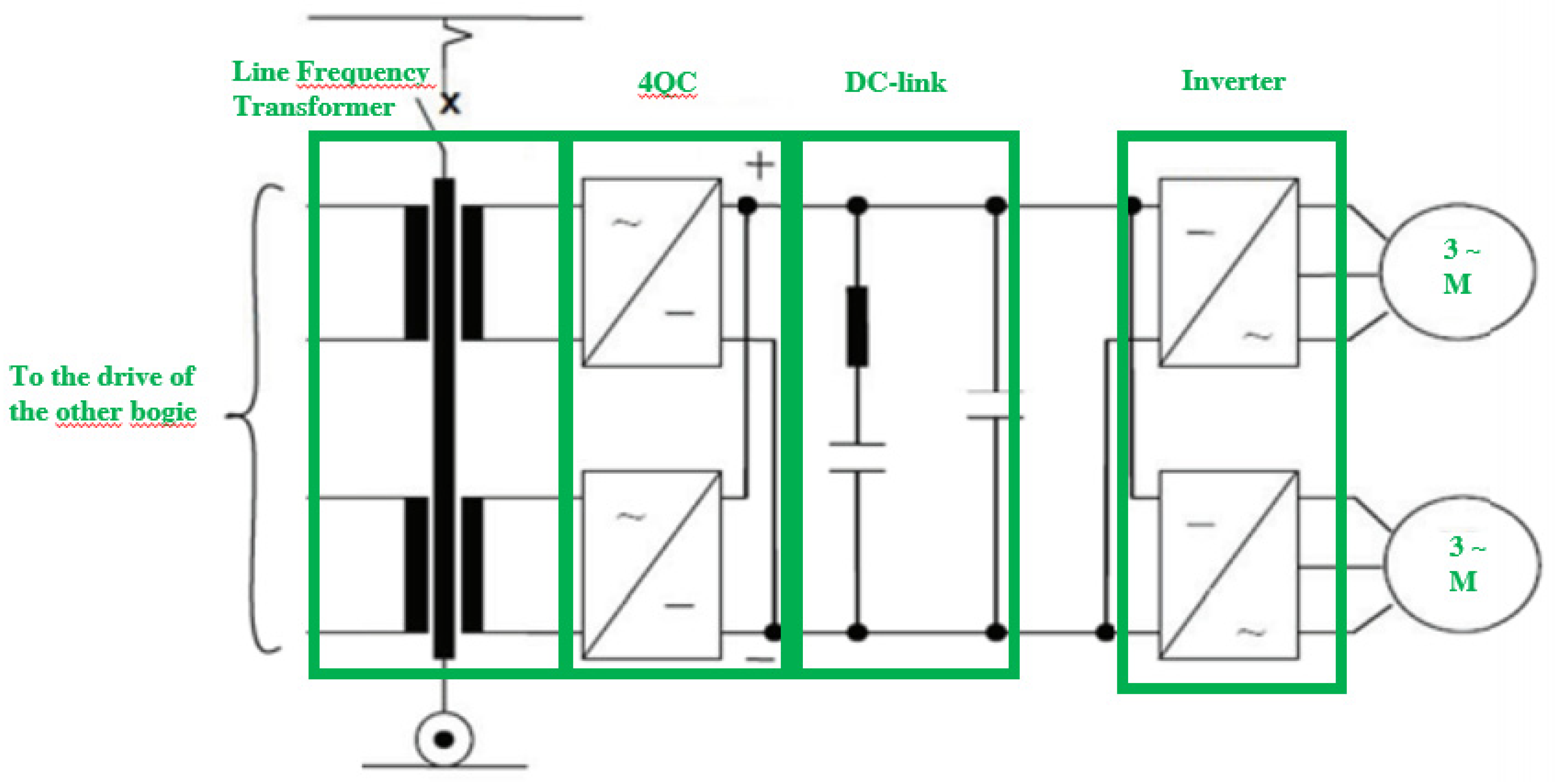
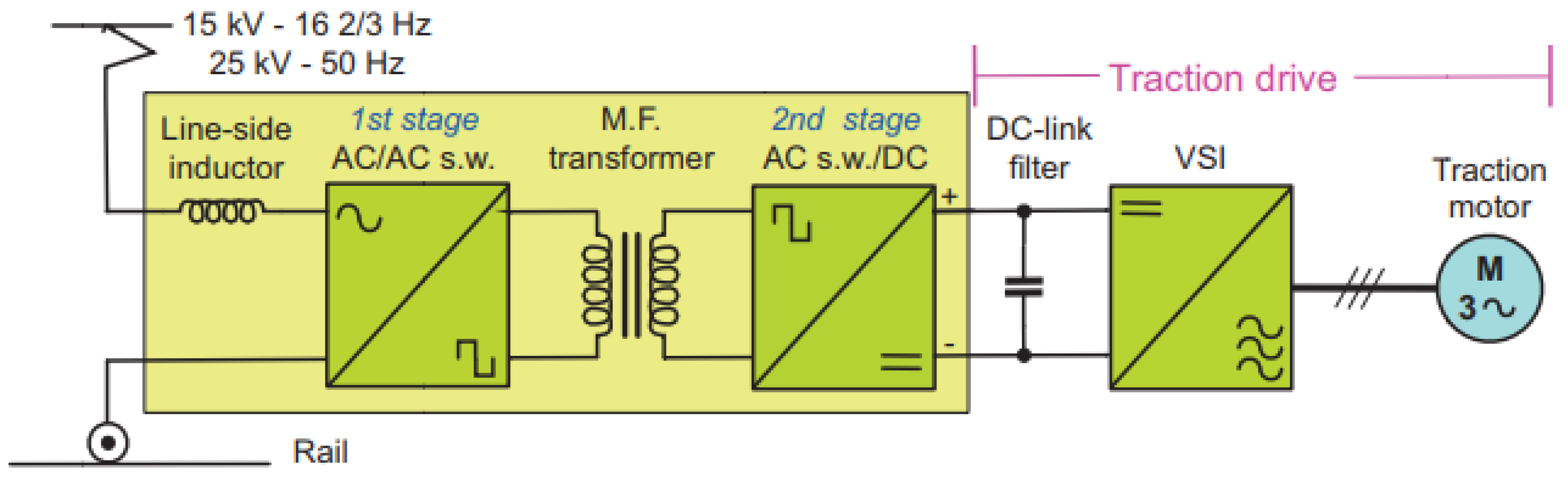
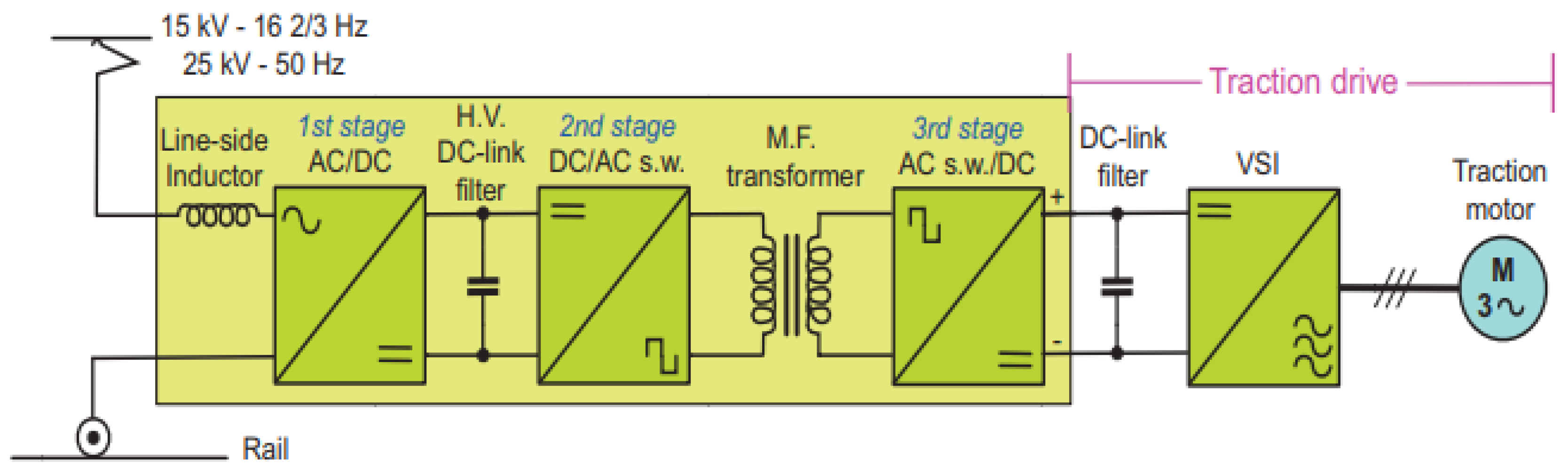
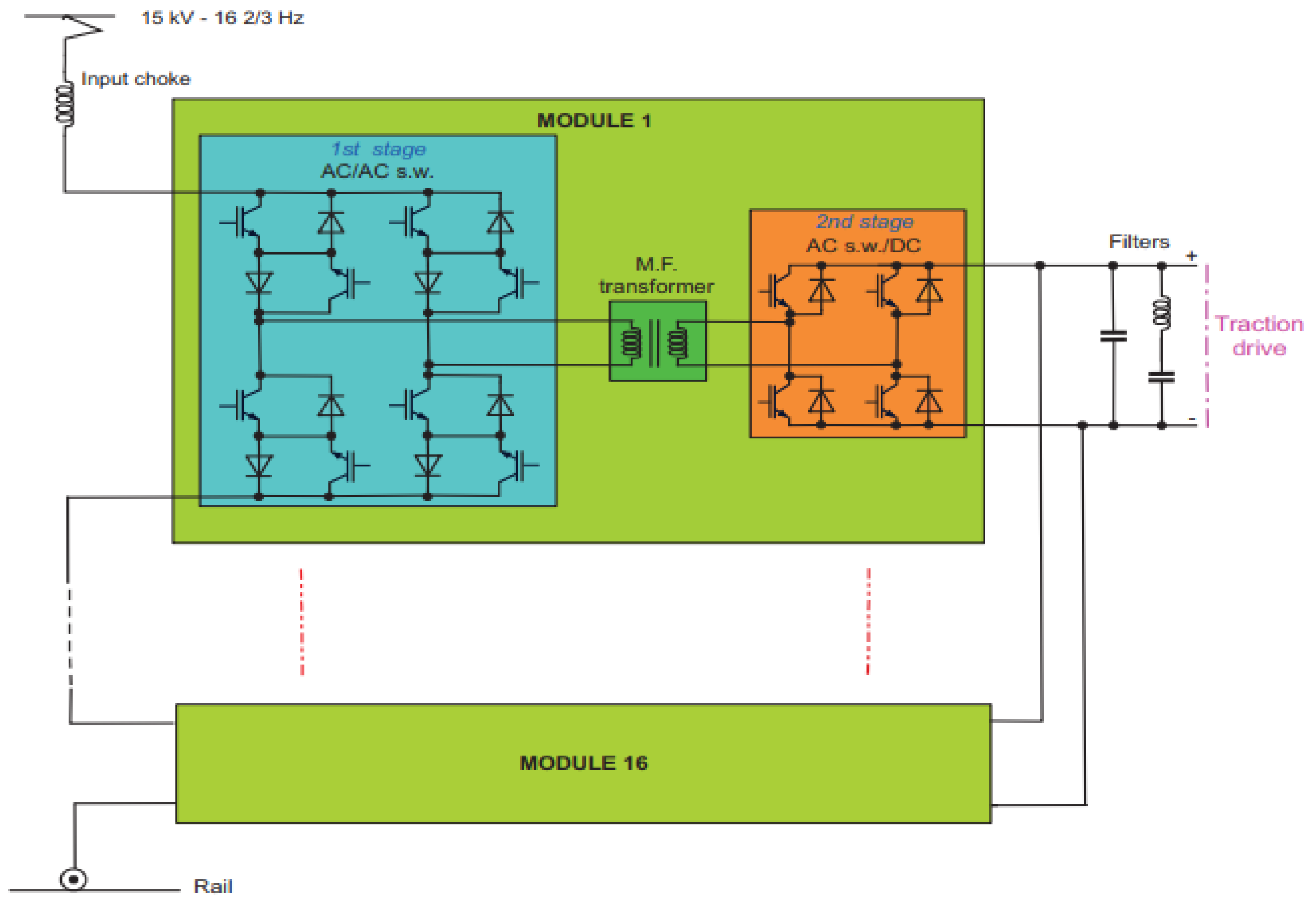
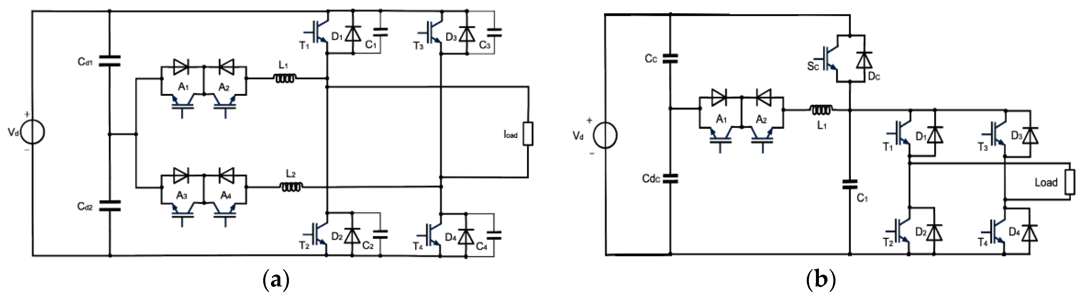
Table 1.
Required number of stages as a function of IGBT peak voltage and line voltage.
| Switch Collector-Emitter Peak Voltage VCEPK | DC-BUS E/VCEPK = 0.55 | Number of Stages Network: 25 kV/50 Hz 29 kVRMS/50Hz * | Number of Stages Network: 15 kV/16 2/3 Hz 18 kVRMS/16 2/3 Hz * |
|---|---|---|---|
| 3.3 kV | 1.8 kV | 23 | 14 |
| 4.5 kV | 2.5 kV | 17 | 10 |
| 6.5 kV | 3.6 kV | 12 | 7 |
| 10 kV | 5.5 kV | 8 | 5 |
* RMS Catenary voltage in the worst case.
Table 2.
eTransformer features.
| Feature | Value |
|---|---|
| Input voltage | 15 kV |
| Input frequency | 16.7 Hz |
| Output voltage | 1.65 kV DC |
| Rating power | 1500 kVA |
| Maximum power | 2250 kVA (30 s) |
| Efficiency | 94% |
| Transformer frequency | 5 kHz |
| Transformer + electronic weight | 2830 kg |
| Output LC filter weight | 385 kg |
| Heat exchanger weight | 255 kg |
| Overall weight | <3600 kg |
| Power density | 0.42 kVA/kg |
| Total number of IGBTs | 52 |
| Cooling system | Forced oil circulation |
Table 3.
Medium frequency topology features.
| Feature | Value |
|---|---|
| Input voltage | 15 kV |
| Input frequency | 16.7 Hz |
| Output voltage | 3.6 kV DC |
| Rating power | 3000 kVA |
| Transformer frequency | 8 kHz |
| Transformers weight 1 | 18 kg |
| Total number of IGBTs | 96 |
| Cooling system | Deionized water |
Notes: Weight for each transformer.
Table 4.
ABB first converter prototype features.
| Feature | Value |
|---|---|
| Input voltage | 15 kV |
| Input frequency | 16.7 Hz |
| Output voltage | 1.8 kV DC |
| Rating power | 1200 kVA |
| Transformer frequency | 400 Hz |
| Total number of IGBTs | 192 |
| Cooling system | Forced oil circulation |
Table 5.
ABB first converter prototype features.
| Feature | Value |
|---|---|
| Input voltage | 15 kV |
| Input frequency | 16.7 Hz |
| Output voltage | 1.5 kV DC |
| Rating power | 1200 kVA |
| Maximum power | 1800 kVA |
| Efficiency | 96% |
| Total number of IGBTs | 72 |
| Total weight | 4500 kg |
| Power density | 0.266 kVA/kg |
Table 6.
Submodule losses in hard-switching.
| Type of Loss | 77 A | 155 A | 230 A |
|---|---|---|---|
| Overall conduction losses | 235 W | 556 W | 962 W |
| Overall switching losses | 10.8 kW | 15.6 kW | 20.3 kW |
| Total losses (efficiency) | 11 kW (69%) | 16.1 kW (86%) | 21.3 kW (91%) |
Table 7.
Submodule losses in ARCP with auxiliary IGBTs.
| Type of Loss | 77 A | 155 A | 230 A |
|---|---|---|---|
| Overall conduction losses on the main devices | 211 W | 468 W | 794 W |
| Overall conduction losses on the auxiliary devices | 328 W | 348 W | 387 W |
| Overall switching losses on the main switches | 93 W | 101 W | 156 W |
| Overall switching losses on the auxiliary devices | 5.52 kW | 5.53 kW | 5.61 kW |
| Total losses (efficiency) | 6.2 kW (80%) | 6.4 kW (94%) | 6.9 kW (97%) |
Table 8.
Submodule losses in ARCP with auxiliary thyristors.
| Type of Loss | 77 A | 155 A | 230 A |
|---|---|---|---|
| Overall conduction losses on the main devices | 211 W | 468 W | 792 W |
| Overall conduction losses on the auxiliary devices | 152 W | 158 W | 169 W |
| Overall switching losses on the main switches | 85.5 W | 89 W | 136 W |
| Overall switching losses on the auxiliary devices | 2.86 kW | 2.86 kW | 2.87 kW |
| Total losses (efficiency) | 3.3 kW (88%) | 3.6 kW (96%) | 4.0 kW (98.2%) |
Table 9.
Submodule losses in AQRDCL.
| Type of Loss | 77 A | 155 A | 230 A |
|---|---|---|---|
| Overall conduction losses on the main devices | 258 W | 402 W | 698 W |
| Overall conduction losses on the auxiliary devices | 173 W | 168 W | 169 W |
| Overall conduction losses on the clamp device | 19 W | 44 W | 138 W |
| Overall switching losses on the main switches | 502 W | 439 W | 640 W |
| Overall switching losses on the auxiliary devices | 3.33 kW | 3.89 kW | 4.17 kW |
| Overall switching losses on the clamp device | 991 W | 1.06 kW | 1.11 kW |
| Total losses (efficiency) | 5.3 kW (82%) | 6.0 kW (94%) | 6.9 kW (96.9%) |
© 2019 by the authors. Licensee MDPI, Basel, Switzerland. This article is an open access article distributed under the terms and conditions of the Creative Commons Attribution (CC BY) license (http://creativecommons.org/licenses/by/4.0/).
Share and Cite
MDPI and ACS Style
Farnesi, S.; Marchesoni, M.; Passalacqua, M.; Vaccaro, L. Solid-State Transformers in Locomotives Fed through AC Lines: A Review and Future Developments. Energies 2019, 12, 4711. https://doi.org/10.3390/en12244711
AMA Style
Farnesi S, Marchesoni M, Passalacqua M, Vaccaro L. Solid-State Transformers in Locomotives Fed through AC Lines: A Review and Future Developments. Energies. 2019; 12(24):4711. https://doi.org/10.3390/en12244711
Chicago/Turabian StyleFarnesi, Stefano, Mario Marchesoni, Massimiliano Passalacqua, and Luis Vaccaro. 2019. "Solid-State Transformers in Locomotives Fed through AC Lines: A Review and Future Developments" Energies 12, no. 24: 4711. https://doi.org/10.3390/en12244711
Note that from the first issue of 2016, this journal uses article numbers instead of page numbers. See further details here.