Investigation of the Impact of Large-Scale Integration of Electric Vehicles for a Swedish Distribution Network


1
Omexom, 653 50 Karlstad, Sweden
2
Karlstads El- och Stadsnät, 651 84 Karlstad, Sweden
3
Department of Electrical and Electronic Engineering Educators, School of Technological and Pedagogical Education (ASPETE), 141 21 Athens, Greece
4
Department of Engineering and Physics, Karlstad University, 651 88 Karlstad, Sweden
*
Author to whom correspondence should be addressed.
Energies 2019, 12(24), 4717; https://doi.org/10.3390/en12244717
Submission received: 24 November 2019
/
Revised: 6 December 2019
/
Accepted: 9 December 2019
/
Published: 11 December 2019
(This article belongs to the Special Issue Electric Vehicle Charging: Social and Technical Issues)
Abstract
:Social considerations for a sustainable future lead to market demands for electromobility. Hence, electrical power distribution operators are concerned about the real ongoing problem of the electrification of the transport sector. In this regard, the paper aims to investigate the large-scale integration of electric vehicles in a Swedish distribution network. To this end, the integration pattern is taken into consideration as appears in the literature for other countries and applies to the Swedish culture. Moreover, different charging power levels including smart charging techniques are examined for several percentages of electric vehicles penetration. Industrial simulation tools proven for their accuracy are used for the study. The results indicate that the grid can manage about 50% electric vehicles penetration at its current capacity. This percentage decreases when higher charging power levels apply, while the transformers appear overloaded in many cases. The investigation of alternatives to increase the grid’s capabilities reveal that smart techniques are comparable to the conventional re-dimension of the grid. At present, the increased integration of electric vehicles is manageable by implementing a combination of smart gird and upgrade investments in comparison to technically expensive alternatives based on grid digitalization and algorithms that need to be further confirmed for their reliability for power sharing and energy management.
1. Introduction
Climate change is one of the greatest social challenges and to remedy this, it is required that the emissions of greenhouse gases must be drastically reduced. In 2009, the Swedish Government established a national vision to be sustainable and energy efficient without electricity emissions of greenhouse gases [1]. The goal is to seize by 2045 the share of electricity-related emissions and then to achieve negative emissions leading to reduction of the emissions by at least 85% compared to 1990 [2].
A milestone along the way is the ambition to convert the Swedish car fleet to be non-fossil by the year 2030 and as such, the emissions of greenhouse gases from domestic transport must be reduced by at least 70% by 2030 compared to 2010 [3]. To this end, vehicles based on non-fossil fuels are financially promoted, the necessary infrastructure is under expansion as well as the benefits and the culture of owning vehicles of alternative technology is promoted to local societies [4]. In Sweden since 2010, the share of electric cars has been continuously increasing every year [5].
All indications show that the distributed generation (DG) will relieve the transmission and sub-transmission networks from the large amount of power demand needed by the end-user customers. However, it is expected that with an increased electrified vehicles fleet increased power demand by the electric vehicles (EVs) owners will emerge, presenting strong geographical variations and time fluctuations as its main characteristics. As such, in addition to the challenge of integrating DG units in the primary and secondary distribution grids, mostly based on renewable energy sources (RES), significant challenges are expected for the development, expansion and investments of the distribution networks [6] aiming to absorb the large-scale integration of vehicles that use non-fossil fuels. In Sweden, given the constraint of an equipment life span of 40 years, the system operator shall take all appropriate measures to achieve such a target [7] in combination to the duty to supply electricity to customers within its geographical concession area [8]. It is already recognized that the planning of investments and grid reinforcement processes became more complex because of the almost countless social and technological variables involved. The network companies have to design reasonable investments based on their experience from customers’ and markets’ behavior. However, nowadays the traditional role of the end-user customer as consumer is considered behind the times and has been replaced by the more active role of the prosumer. Therefore, a future investment should be based on predictions of future technology, prosumers’ production and consumption expected patterns, assessment of customers’ adaptation on new business models and all that considering existing laws, rules and regulations, which may change over time [9].
The large-scale integration of EVs will change the electrical energy consumption patterns of the distribution grids. Consequently, it will be of great importance for the network owners to take into consideration this aspect during planning of network investments [10]. EVs are primarily considered direct current (DC) loads however, at the same time might be considered as storage devices (SD), in other words as electric power sources. In this manner, EVs could also have a supportive role for the grid when the system operator sees fit such an operational mode. Hence, network owners should be aware of how their grids could be affected by future expansion of EVs usage in order to be proactive to minimize future negative impacts and in parallel to create and then use advantages arising from a high penetration of EVs [11].
The European Union’s climate policy has set targets to reduce the transport sector’s share of greenhouse gases in the form of carbon dioxide (CO2) by 60% and to reduce the proportion of vehicles powered by conventional fuels in urban areas by 50%. To achieve this, it has established a strategic process for the planning of the networks necessary to achieve the objectives in collaboration to network owners, industry and researchers [12]. The work highlights the so-called key factors that need to be taken into consideration when planning future networks such as power quality, relative load of network components, network capacity and others. In the report, it is predicted that about the year 2050 the most accepted power level for private charging will be 11 kW. Moreover, simulations show that the economic incentives and the dynamic scales will greatly affect the charging behavior of private owners, which should be considered for dimensioning the power system. Of paramount importance, the smart grid technology promises a positive impact on future distribution grids. Simulations show strong smoothing on consumption curves, which minimizes and delays the need for reinforcement. In addition, the public charging infrastructure is advantageous because reduces home charging, thereby relieving the low voltage grid (LV). It has emerged in a study conducted in Ireland that private EVs owners most likely recharge their vehicles at home and that similar charging tendencies apply to other countries with EVs in its fleet [13].
In [14], a fleet of 2340 EVs of different sizes and having charging power 3.3 kW was investigated in terms of driving and charging behavior in an urban environment in order to examine how the LV network is affected. The result demonstrates that 93.3% of the owners prefer to charge outside the more expensive hours. The report makes use of a tariff that raises for the energy used during the hours from 7:00 to 22:00. Outside these hours, a significant power spike in the system arises.
In the study presented in [10], simulations on an existing regional network have been conducted in order to describe its capabilities and identify potential bottlenecks for high EVs penetration in the future. The purpose of the study was to serve as a basis for planning for the next 20–30 years, in this case until 2040. The study simulated EVs penetration in increments of 16%, 50% and 100% in combination with various types of electricity network tariffs. It is believed that the most likely home charging power in 2040 will be about 11 kW. The study demonstrates that the receiving substations are capable of 16% penetration of electric vehicles and they generally begin to fail at about 50% and then totally collapse at a higher penetration. A key finding was that the dynamic tariffs could relieve the network and at the same time might lead to additional power peaks in the system. Specifically in [15], the results of a modeled 10/0.4 kV network indicate that the grid has a capacity for home charging about 20–40% and that even at this low penetration of home charging, voltage quality might be poor and power supply cannot be ensured in all cases.
In [16], the impact of EVs penetration in increments of 25%, 50% and 100% on the distribution network in the UK is investigated. Two charging levels of 3.3 kW and 6.6 kW were selected, assuming 1.3 EVs per household. Simulations were carried out with different types of load behavior. The simulations demonstrated the significance of the supplying transformers’ rated power where cases at which a transformer might be loaded nearly half while another transformer could be overloaded by more than 40% and one of substation transformers failed already in EVs penetration of 25%. Similar results have been reported in the literature that in addition to the transformers mentioned, the cables was strained hard during uncontrolled charging behaviors.
The available technology in the power systems market offers several alternatives for EVs charging, either at residential areas or in the urban network. There might be also different charging levels, using dedicated AC or DC power lines for a variable number of different hybrid vehicles, not exclusively EVs. Among these alternatives, in the presented investigation the interest focalizes on home charging for private EVs owners with regard the question how well the network cables and transformers stand up against the prevailing load. The EVs are considered as passive loads and several scenarios regarding the charging power are examined. Modern distribution grids are evolving towards the smart grid concept. The smart grids are developed on the basis of tools, devices and processes that realize better control, operation, management, planning and metering for the future grids. According to Luis Hernández-Callejo [17], smart grids involve advances in the four main fields, which are Operation and Control, Maintenance and Lifespan Management, Grid Planning and Design as well as Metering. These areas present strong interrelation where information from the one area might be interpreted as input for the other areas. As such, high flexibility and several alternatives for the grid utilization are offered however, the practical, technical and implementation complexity increases accordingly. Hence, such advancements are promising for future power systems but their implementation in the network infrastructure is not an easy task. In [18], Marzal et al. demonstrate that communication will be a major factor in achieving the status of future smart grid. As such, deep digitalization and big data analyses and handling are required to be developed as well. Hence, the future smart grid approach requires time and substantial resources before becomes completely materialized. In the meanwhile, the connection of EVs is increasing constantly. The distribution system operators (DSOs) face the electrification of the transport section in its real manner that of the increased demand of electrical power and the necessary infrastructure investment. Until the smart grid concept is technically capable to handle the integration of EVs, the levels of penetration are expected to be very high [5]. Having mentioned the above, EVs integration demands need to be met using the current infrastructure and the already established procedures, at least for a transitional period of some years until the smart grid concept is substantially utilized in the distribution grids. In this regard, this study is conducted about the impact of large-scale integration of EVs in order to directly applicable alternatives be proposed based on the current grid topology, metering, communication and automation equipment or smart implements such as meters and chargers that are gradually embedded in the current grids.
In this paper, the large-scale integration of EVs in a Swedish residential distribution network has been investigated by taking as integration parameters: (i) the EVs’ penetration as percentage of residences that utilize EVs and (ii) the charging power level per EV. The study is based on the current grid infrastructure facilities and in addition, implements social aspects of EVs integration patterns as it is proposed in the literature and the apply in the Swedish culture. Specifically, the pattern of customers’ intentions for the expected integration of EVs is taken into consideration with the aim to investigate the impact of the abovementioned EVs’ integration parameters on the distribution grid. In addition, the presence of smart grid charging modes is being examined. The parameters that are under consideration for the analysis of the network are the relative transformer loading conditions, the loading current of cables and the voltage drops of the distribution grid for both the LV and the medium voltage (MV) of the distribution grid. Industrial software tools, proven for their adequate accuracy and widely utilized by the DSOs, are used for this analysis. The results of this case study present similarities to findings reported in the literature and the particularities and capacity capabilities of the network under study are demonstrated. Moreover, feasible investments and grid reinforcement alternatives which are not based on extended digitalization that could relieve the distribution network are discussed. This study is taken as basis for forthcoming investments planning to the network under examination.
2. Integration Method and Assumptions
2.1. Social Aspects on EVs Integration Patterns
According to the analysis of Valdez et al. [19] at Milton Keynes, in the United Kingdom the early embracing of electromobility will be supported by “pioneering and prospective adopters” rather the general public due to the lack of subsidies and charging infrastructure. This translates practically into local load increases on the grid where adopters reside. Nosi et al. [20] investigated the conditions that could potentially encourage millennials to use EVs in Italy. Youngsters are important clients for the new technology; however, this could create higher consumption in the vibrant areas of urban networks. In the San Francisco (CA, USA) area, the higher incomes and education level residents lead to a higher probability of owing EVs [21]. This demands higher power grid investments in neighborhoods with educated citizens. For EU countries, and especially for Germany, Austria, Spain, Netherlands and the UK [22], subsidies and tax reductions for EVs have created a smooth environment for increasing their penetration. In China, electromobility is rapidly expanding [23] and this strains the networks, which however, are also under radical development. In Norway [24], more than the half of new vehicles on the road are electric. This is due to the general perception of the public that the future is electric and green. All members of the society contribute equally in this direction. In this case, as far the power system is concerned, the penetration of EVs is increasing linearly across the whole grid. These studies indicate that behavioral integration patterns for the adoption of EVs are not universally aligned. Having mentioned the above, an investigation in order to reinforce a power grid due to the connection of EVs, is a challenge that shall be tackled using distinctive approaches for different networks. The Swedish society already faces the impact of climate changes, as for example the extended fire at North Sweden in summer 2018 due to extreme and for a long-time period dry weather and the shrinking winter period, which affects the national industry and the financial business models. Hence, in the same manner as at Norway, there is general perception of the public in favor of a sustainable and greener future. Moreover, in Sweden, people having different education levels and economic background contribute equivalently to the EV market and thus, the EV integration presents a uniform geographical distribution. This is because bank loans offered in combination to the Swedish tax rules encourage the public to adopt a greener lifestyle by turning to residential RES and EVs. Consequently, in this study, the inherent analogy that arises from the above arguments is depicted by a linear EVs integration pattern like that at Norway by suggesting 1.2 EVs per house.
2.2. Electric Transportation in the Swedish Network
The Swedish electrical power system consists of 15,000 km power lines, 160 substations and 16 interconnections [25]. The power system functionality is of national interest and therefore, the network is state-owned where the responsible authority for the national grid is called Swedish Power Grid. The Swedish Energy Inspectorate (EI) is a supervisory authority on behalf of the Swedish government that sets the rules on the energy market and decides how they intend for it to evolve. The Energy Inspectorate aims in the long term to have an effective, safe, solid and sustainable energy supply. To this end, the EΙ conducts oversight activities of energy companies that provide electricity, natural gas and district heating. The Energy Inspectorate reviews and ensures that energy companies comply with the laws, rules and regulations that apply. The efficient usage of local and regional networks are valued by using two indicators, load factor and the ratio of net power losses over the energy fed into the network [7]. The load factor gives an indication of how hard the network load is used. Grid losses are divided into technical losses and non-technical losses. For the technical part, heat and corona losses count while, the non-technical losses are referred to measurement errors, lack of measurement, the energy for optimal operation (e.g., cooling of plant) etc. Network tariffs are established in accordance Swedish laws and must be unbiased and non-discriminatory. They should be designed in a way that is consistent with the efficient use of the electricity network and efficient generation and use of electricity [26]. Non-discriminatory means that customers of the same kind have the same charge. It may only be different if there are clear objective differences of a customer over another. The companies have combined network fees to cover the reasonable costs for a reasonable return for their services.
In 2018 in Sweden, 48.444 rechargeable vehicles were registered, of which 28% of these were EVs and 72% were plug-in hybrid electric vehicles (PHEVs). The number of rechargeable vehicles in Sweden is increasing exponentially and the forecast for the coming years puts Sweden in third place in Europe for newly registered PHEVs and EVs (2030 Secretariat). Generally, in normal operation the PHEVs and EVs consume about 20 kWh per 100 km. The charging time of the battery depends on battery capacity itself and the on-board charger [27]. Charging power levels of 3.7 kW to 6.6 kW apply to most EVs available in the market.
There are four charging modes [28] that are defined in the international norm IEC61851. Mode-1 involves termination of the vehicle in a conventional 230/400 V outlet having a rated power of not more than 16 A, maximum 250 V single-phase and 480 V three-phase. Charging mode-2 means that the mode-1 presents an increased rated current of 32 A. Mode-3 involves charging through fixed mains-loading stations between the vehicle and the network. The loading stations are 230/400 V with a maximum rated current of 63 A, and they possess built-in controllable functions. The control function is able to regulate maximum power output and charging sessions to avoid an increased burden on the local network [28]. Since 2017, mode-3 is the standard charging method within the EU [29]. Mode-4 has a maximum rated current of 400 A, 400-1000 V (DC). There are special type sockets and connectors for these modes of charging. Type-1 connectors handle 32 A single phase and are mainly dedicated to Asian vehicle models. Type-2 is the standard in Europe and manages 63 A three-phase and alternatively 70 A single phase. Combined Charging System (CCS) is a type-2 connector with an additional connector for direct current, also corresponds to the CCS standard in Europe. CHAdeMO is a Japanese standard for DC charging [30].
Categorization of charging power is not clear and hence, the charging levels that are described in the Swedish regulations are used. Temporary charging could be used for power levels 2–3 kW but is not recommended because the terminals are not designed to be used for many hours at their maximum current and as such there is high possibility of fire hazards. For normal charging, the single-phase and three-phase mode-3 charging in the presence of type-2 connectors is recommended for charging power above 3 kW to 50 kW. Fast charging over 50 kW in unity power factor is accomplished by using DC chargers with mode-4 and CCS contacts connectors [27].
In this study, mode-3 charging by using type-2 connectors is assumed. The charging power constitutes a variable parameter in this study in order to evaluate the impact of charging rate on the distribution grid. To this end, several charging levels have been investigated leading to the four scenarios of 3.7 kW, 6.9 kW, 11.1 kW and controllable smart charging. Smart charging is explained in the next section.
2.3. Smart Grids and EV Charging
One can interpret as a smart grid the combination of the available technology, regulations and functions in order to achieve reliable operation of a network in an environmentally and economically sustainable manner. In this manner, the smart energy systems facilitate the integration of DG, by means of mainly RES, of SD and EVs. The power network is evolved to an active grid presenting bi-directional power flow, self-healing properties and all necessary dynamic functions with aim to balance the supply to the demand and to minimize the risk of failures [31]. Automatic control and bi-directional communication is of key importance to realize the smart grid concept. Advanced meter infrastructure (AMI) has a key-role on the grid monitoring that allows the customers to act as prosumers and take part in several operational schemes such as demand response, electricity pricing schemes and distributed automation schemes. Demand flexibility is an intended interaction between the customers and the supply companies. According to this interaction the customers may vary their demand profile, or the companies may have access to modify the customers demand profile in order to optimize the grid operation by following a pre-established contract agreement. As such, the involved stakeholders have taken the heavy burden to investigate and develop suitable new business models, tariffs, laws and regulations. In this operational manner, EVs may have a twofold role. They may absorb energy acting as typical passive units (DC loads) in a grid-to-vehicle (G2V) function as well as they may release energy acting as active units (DC sources) in a vehicle-to-grid (V2G) function. Consequently, the EVs might be used as controllable electrical loads or controllable electrical sources and therefore, they may offer supportive services to the electrical smart grid concept. A comprehensive review on the important areas of research and development for smart grids as well as future scenarios that will make possible the transition to the future smart grids is presented in [17].
Communication between the access point and the vehicle when charging allows for the so-called “smart charging” with dynamic load balancing. The technology is based on control equipment installed between the power meter and the charging point such that communication is established, the so called as “smart meters”. Such meters will have a key-role in the future electrical systems by actively taking part in the wider electrical systems’ AMI. This communication channel is in charge of recording in real time both the house load consumption and the charging rate of the EVs in order to dynamically load balance the services being provided [32]. The dynamic load balancing in practice means that the energy provided for charging the vehicle is regulated by the main fuse size. This leads to that the maximum energy capacity may be utilized for charging as it is computed by the instantaneous energy difference from the customer’s power throughput and instantaneous power consumption. Hence, the installation is never overloaded and the main fuse never switches off [32]. In this field, exceptional improvements on the future applications are expected by introducing internet and Wi-Fi technology facilities integrated in building installations [33]. This will considerably simplify the installations as well as will offer higher flexibility for automatic control and energy management. Furthermore, dynamic load balancing would be achievable when several EVs charge simultaneously and at different access points connected to the same supply point. The available power is then optimally distributed between the EVs by following established priority rules. In this study, the interest about the EVs is focused on the G2V operational mode as controllable passive loads. In the fourth scenario the EVs charging power is adjustable to the main fuse capacity in respect to the customer ratings.
2.4. Network under Study
This study has been conducted for a part of the distribution grid at Karlstad city in the Värmland region in Sweden. The company that owns the distribution grid has invested since 2018 about 6 MEuros for grid reinforcement, replacement of grid-units that will expire soon, new installations as well as in order to cope with the increased integration of DG, mostly photovoltaics PVs and EVs in the Värmland region. This study examines the impact of large-scale integration of EVs for a particular part of Karlstad’s distribution grid for both the MV and LV levels. This case study investigates the real ongoing problem under real conditions and by using common industrial tools such as those utilized by Distribution System Operators (DSOs). Specifically, historical consumption data for real network during the heavier winter of the last years are embedded as well as realistic assumptions of the customers’ needs and the social behavior regarding the power charging and EV penetration levels are adopted as mentioned above. The growing integration of RES that takes place in residential areas has been already investigated in [34]. The existence of locally produced electrical power such as from residential PVs is widely accepted that further relieves the LV and MV grids. As it is mentioned in the “Electric transportation into the Swedish network” and in the “Social aspects on EVs integration patterns” analyses above, the tendency is for home charging. Hence, local power generation can partially cover the home charging load. At this point, it is a subject of a forthcoming research investigation the impact of distributed storage (DS) by using SDs consisted of either batteries or other media.
This study applies to the Henstad area in Karlstad region, as shown in Figure 1. This network is fed by two power lines, Line-23 and Line-27, respectively, which in turn are connected on the 12 kV grid as depicted in Figure 2. Each line brings four substations transformers, which in turn supply several customers. The feeders operate as a radial network, but also, by creating a loop between the T273 and T274 transformers, they can operate as a loop. Seven transformers feed residential loads and T422 is dedicated to an industrial load.
2.5. Computational Tool, Data and Simulation Scenarios
The simulations in this study were conducted by using the dpPower software tool which is the web-based geographic information system that the local DSO uses. The program visualizes the distribution network along with maps and topologies. The software is used to make estimates for renovation and new construction, various types of calculations relevant to the area, finding the right dimensioning, documentation of all sites with data and the commissioning date as well as were in the map the facility is located. dpPower is capable of simulations and changes in the network and then respond for the appropriate modification and actions, for example in case of overload situations.
The above network under study has been inserted in the dpPower version used by the DSO and as such all documentation about substations, cables, transformers, customers, energy consumption for both the MV and the LV grids was stored in databases. Access to these databases has been given in order to realize this investigation but these data are confidential and cannot be further presented in this paper. However, some of them will be disclosed to present, analyze and evaluate the results in the next section. The recorded energy demand data from previous years had been inspected and the hardest available recorded winter consumption to build the simulation scenarios for the study is used.
In this study, home charging at a power factor of 0.9 by utilizing the total capacity of the home feeder as it is rated by the implemented fuse is assumed. Most of the residential customers utilize a 25 A fuse and in general, the fuse size is equal or less than 63 A for all types of customers’ connections.
Four scenarios are assumed, depending on the charging power level, which are 3.7 kW, 6.9 kW, 11.1 kW and smart charging (further called load-controlled). Load-controlled means that the charging power of the connected EVs is regulated in order to the maximum available currents up to the fuses’ rated values are utilized.
Five scenarios are also adopted depending on the EVs penetration level, which are 16%, 25%, 50%, 75% and 100% or 92% in the case of load-controlled scenario. Although there is no connection between a customer’s geographical location and its energy consumption, the insertion of the EVs started from the houses that mostly contribute to the substation transformers’ currents in order to symmetrically maximize the network load.
3. Results
In order to assess the capabilities of the distribution grid to absorb the EV high penetration and what the needs are for future investments would be, grid calculations have been done according to the abovementioned scenarios. Specifically, the interest focuses on: (1) the regulation of the voltage drop limitation of 5% according to the Swedish standards, (2) the safe operation of wiring that means avoiding any violation of the cables’ rated currents and (3) the transformers loading conditions. These calculations have been done for both the LV and MV networks and for all transformers and their associated cables. These results cannot be presented in their original form of extended lists of calculated values and as such, have been summarized and presented in form of tables. The analyses of the results in each scenario for both the LV and MV grid follow.
3.1. LV Network Calculations
3.1.1. Charging Power 3.7 kW
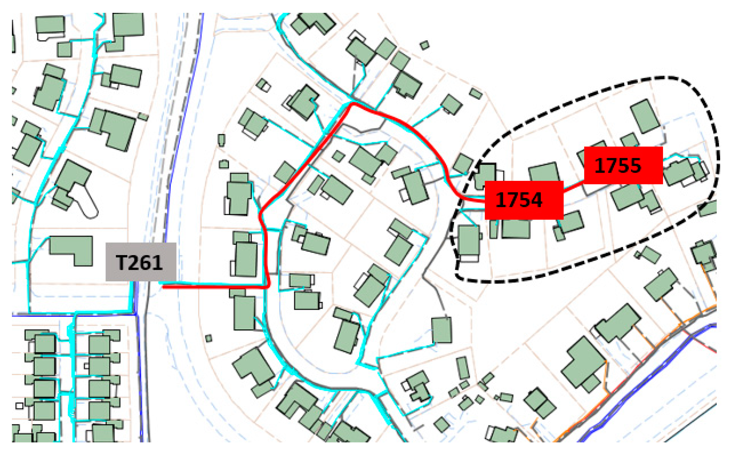
The results for this scenario are presented in Table 1. At 3.7 kW charging power and 100% EVs penetration, at is shown in the table 99.23% of Line-23 and 99.52% of Line-27 total cables can handle the load. The small percentage that exceeds the 5% voltage drop limit is because of the customers’ distance from the feeding transformer. For the Line-27, a distant house is positioned at 430 m away from feeding transformer T261 and is connected to cable cabinets 1755, as one can see in Figure 3. For the Line-23, the 5% regulation violation is due to two customer that are 600 m away from feeding transformer T272.
3.1.2. Charging Power 6.9 kW
In this scenario, on the level of 50% penetration of EVs a small percentage of wires that cannot meet the 5% voltage drop regulation appears, as the results in Table 2 present. In particular, Line-27 has five customers that are connected to cable cabinets 1755 in Figure 3 whose voltage drop exceeds 5%. For Line-23, 99.62% of the cables successfully hold the voltage drop according to the rules and only one customer suffers from a voltage drop higher than 5%. At 75% penetration, the percentages of cables that hold the voltage drop requirements further decrease. The problems appear with the more distant (cabinet 1755 on Line-27 in Figure 3) and heavier use customers. In the case of 100% penetration, the situation becomes more stressful, especially in the case of Line-27 where only 86.6% of the cables present proper operation in respect to 5% voltage drop rule. In particular, as seen in Figure 3, the distance between transformer T261 and cabinet 1754 is 311 m and as such the connected on this cabinet and on cabinet 1755 customers become too far distant.
3.1.3. Charging Power 11.1 kW & Controlled Load
In this case, as it was expected the situation becomes even harder than the above mentioned cases of 6.9 kW and 3.7 kW. As the indicative calculation in the Table 3 shows, one should mention that only 57.89% of cables do not violate the 5% rule in the Line-27. Moreover, in this scenario violations of the safe operation of the cables appear because there are cases where the load current is higher that the cables’ ratings in Line-23. However, it should be mentioned as well that 11.1 kW for higher levels of penetration for simultaneous charging is not one the most probable scenarios that might happen. However, since this could be a potential real case operation, one has to take it into consideration and prepare appropriate measures against such failures. To this end, the case of controlled loading conditions has been explored.
As one observes from Table 4, in the case of controlled loading conditions the situation has been noticeably improved and in the worst case 77.03% of cables present proper and safe operation according to the regulations. The lowest percentages of cables that display proper operation is related to the dependence of the voltage drop on the distance. At higher consumed power levels, the networks that experience severe loading conditions are those that have longer distances between the network transformer and the cable cabinets. Moreover, there are no cases for the cables at which the safe operation is violated.
3.1.4. Analysis of the Results for the LV Network
The network connected to transformer T274 presents the best performance in all scenarios except the case of 11.1 kW, 100% penetration for the cable having receiving end at cabinet 1710. In this particular case, the cable current exceeds the cable’s rated current.
In contrast, the network associated to transformer T261 experiences the most severe loading conditions in several operational scenarios. Table 5 presents the total length of supply cables, the longest outgoing supply cable and the number of customers for each transformer.
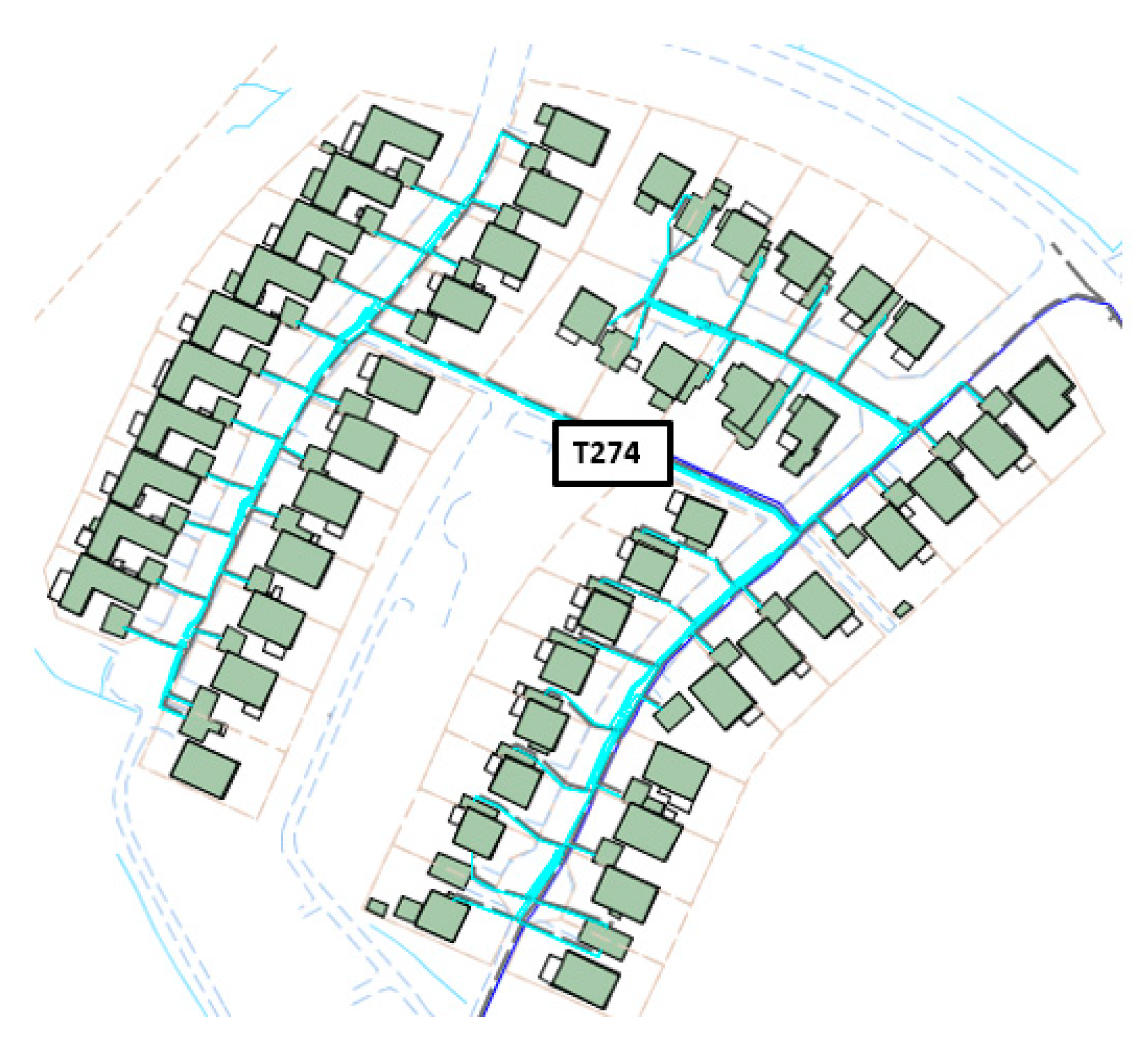
One can observe that T261 has the second highest total supply cable length, the lengthiest outgoing power cable and the highest number of customers, while T274 has the second lowest total supply cable length, the shortest outgoing power cable and the second lowest number of customers. This partially explains the reason why the network associated to T274 presents the best performance among the other parts of the LV network. In addition, comparing Figure 4 to Figure 5, one can clearly see the topology differences in these two networks. In Figure 4, the left part of the LV network that is served via transformer T261 has many more cables and distant customers than the right part. In Figure 5, one can see that the transformer T274 is located in the center of the LV network it serves which means the shortest possible distance to all connected customers. Hence, the LV network connected to T274 is more balanced and lighter than the LV network connected to T261 and consequently, presents better performance in comparison.
Figure 6 visualizes the under examination LV network by means of the total length of supply cables, of the longest cable (times 5) and of the number of customers (times 20) for all transformers except transformer T422 which serves a single commercial customer. From this radar graph, one easily identifies how much of the LV network each transformer serves. It is obvious that T261 and T270 experience heavier loading conditions by means of customers and cables while T273 and T274 experience lighter loading conditions. Nevertheless, the grid’s technical details should be taken into account under several circumstances. By comparing the case scenario of 11.1 kW for 75% and 100% EVs penetration a substantial difference, especially for 100% penetration, appears between Line-23 and Line-27. The difference is because some cables in the network served by Line-23 are reinforced. Transformer T272 has one reinforced section of 240 mm2 for 273 m in total, T271 has two reinforced sections of 240 mm2 for 706 m in total and T270 has one reinforced section of 240 mm2 for 175 m in total. However, by comparing the performance of the two networks, the one supplied by Line-23 and the other supplied by Line-27, for the controlled load scenario for 75% and 92% penetration in relation to 11.1 kW scenario for 75% and 100% penetration, a lesser extent of that difference is observed.
3.2. MV Network Calculations
3.2.1. Normal Operation of Line-23 and Line-27 as Separate Lines
In respect to Figure 2, Table 6 and Table 7 present the network calculations for the MV network cables’ currents as percentages of the cables’ rated currents in all scenarios for both Line-23 and Line-27, respectively. It is observed that the load currents are very small in comparison to the cables’ rated values and as such, the MV network is obviously well within safe operation margins. As regards the voltage drop, although it is not shown in the Tables, the calculations reveal that there was no violation of the 5% voltage drop rule in all cases due to the low percentages of the relative currents.
Table 8 and Table 9 present the loading of the transformers for all scenarios for both Line-23 and Line-27, respectively. One observes that even from 6.9 kW charging power and 75% EVs penetration overloading of the transformers start as for T274 in Line-23. The transformer T422 in practice remains unaffected because it serves a single industrial load. The controlled load case scenarios slightly relief the transformers overloading stresses. The 500 kVA transformers such as T272 and T274 in Line-23 as well as T273 in Line-27 present overloading at lower combinations of EVs penetration and power charging level in comparison to 800 kVA rated transformers as T270 and T271 in Line-23 as well as T261 and T262 in Line-27.
3.2.2. Combined Operation of Line-23 and Line-27 as in Reserve Mode
In respect to Figure 2, Table 10 and Table 11 present the network calculations for the MV network cables’ currents as percentages of the rated currents in all scenarios in the first case when Line-23 feeds Line-27 and in the second case when Line-27 feeds Line-23, respectively. For both feeding condition cases, at the level of 11.1 kW and 75% penetration or above, for the cables that are closer to the lines connections, violation of the safe operation rules is observed. Moreover, the control of the load does not guarantee relief of this loading stress in any case as well. As regards the voltage drop, although it is not shown in the tables, the calculations reveal that there was no violation of the 5% voltage drop rule in all cases including the cases where overload was observed.
Table 12 and Table 13 present the loading of the transformers for all scenarios in the first case when Line-23 feeds the loop and in the second case when Line-27 feeds the loop, respectively. One observes that even from 6.9 kW charging power and 75% EVs penetration overloading of the transformers occurs as for T274 in Line-23 while T422 in practice remains unaffected because it serves a single industrial load. The controlled load case scenarios does not relieve the transformers overloading stresses. The 500kVA transformers such as T272, T274 and T273 in present overloading at lower combinations of EVs penetration and power charging level in comparison to 800 kVA rated transformers as T270, T271, T261 and T262. By comparison, the case where Line-27 feeds Line-23 is slightly worst. This is because Line-23 has more customers than Line-27 and as such, more power is transferred to a longer distance resulting to higher power losses along the cables.
3.2.3. Analysis of the Results for the MV Network
The calculated results indicate that the MV cables do not suffer from overcurrent conditions or higher than 5% voltage drop for any percentage of EVs penetration and charging power level under normal operation of the primary distribution grid. In the cases where the one line feeds the other, there might be some overcurrent situations for which the controlled load scheme operation does not relieve the cables in any case. However, it should be noticed that even in such cases of overcurrent there is no violation of the 5% voltage drop limit.
As regards the transformers, the results reveal the high impact of the EVs integration, percentage of penetration and charging power level as well, on overloading conditions. Overloading of the transformers appear even for low charging power levels and middle penetration percentages during normal operation of the primary distribution network. In the case where one line feeds the other, the overloading stress on the transformer remains on the same levels while load control does not seem to bring any relief.
4. Discussion
According to the results, both the LV and MV networks bring adequate capacity to initially cope with the integration of EVs in the distribution level. Almost 100% penetration of 3.7 kW charging power and approximately 50% penetration of 6.9 kW charging power is achievable for the LV network. On higher penetration and charging power levels, proper operation and safe operation issues appear. This means that either the 5% voltage drop limit or overcurrent problems appear for the LV cables. The results indicate that for charging power of 6.9 kW, 11.1 kW and for the controlled-load scenarios, a percentage up to 25–50% EVs penetration is manageable from the grid in its current state without any investment. However, the load-controlled scenario reveals that smart charging strengthens the LV grid capabilities. It should be commented that this means investment from both sides of the grid owner and the customer as well. From the customers’ perspective, the implementation of smart chargers and smart meters gradually become a common tactic. From the grid owners’ perspective, smart grids technology implementation is not the only option. In cases where additional loads are inserted in a certain network, grid upgrades might be required such as cable and transformer resizing.
Table 14 presents the percentage of total cables that handle the load for the hardest case scenarios of 100% penetration for 11.1 kW and 92% penetration for controlled load in comparison to 100% penetration for 11.1 kW when only the LV cables have been redimensioned. The results reveal that by redimensioning the LV cables, the LV network appears to be much stronger than a smart controlled LV network. At this point, it should be highlighted that there is no assessment of the cost that follows these investments and as regards the voltage drop and overcurrent limits, LV cables re-sizing appears more beneficial. Total cable replacement is not suggested as good practice for economic reasons. It could be a part of a new grid expansion. In addition, there are substantial arguments in favor of the smart grid investments such as grid monitoring, energy management and optimization, control and stability as well as power quality. Several alternatives have been proposed to perform intelligent management for domestic, commercial and industrial customers in the presence of EVs, DG and SDs systems [35,36]. Hence, combined smart techniques and targeted grid upgrade could relieve the LV network under study from safe and proper operation issues in an economically and technically feasible manner.
As regards the MV cables, there are no issues of safe and proper operation in relation to the EVs penetration and charging power levels. Only some minor problematic incidents due to cables’ overcurrent operation might appear when the one line feeds the other. As regards the transformers, important operational overloading problems are revealed. Loading stresses higher than 80% of the rated load appear for 6.9 kW and 75% EVs penetration. In case of more extended EVs penetration and higher charging power levels, the transformers appear overloaded in any case. In addition, the controlled-load case does not have any impact of these severe loading conditions. As such, the transformers are the most vulnerable units of the distribution grid in its current state without any upgrade. From a technical point of view, a first alternative might be to re-size the transformers ratings according to predefined load demands. Transformers’ ratings re-sizing is a technically correct alternative to be further explored which might be also combined to grid expansion demands but it is beyond of the scope of the presented investigation. However, this is not the only alternative because DS in combination to DG offers new grid expansion and investment capabilities [37,38].
Energy storage is one the most promising proposed techniques that is mostly combined nowadays to AC/DC microgrids because offers several alternatives ranging from simple energy storage services to voltage stability [39] and energy management solutions [40]. In addition, optimal charging controllers for coordinated charging of EVs [41], decentralized control schemes in order to enhance AC/DC microgrids stability [42], as well as artificial intelligent methods (AI) such as machine learning (ML) open new horizons for the power systems management [43].
The present market and social behavior in the Nordic countries give prominence to the fact that the DSOs need to cope to the ongoing real problem of the high levels of EVs integration by utilizing the distribution grids current capacities in combination to economic and technical viable grids investments. As such, it is of paramount importance to assess the offered grids’ capabilities for the integration of new additional loads. Solutions based on high-level smart grids technologies, implemented in AC/DC microgrids, offer a breeding ground to deploy the abovementioned alternatives. However, from a technical point of view such proposals are based on extended digitalization of the power grids, usage and installation of a large amount of sensors and at the end of this process big data handling and storage. Consequently, the reliability and applicability of these alternatives need to be further explored, new business models need to be developed and as such, their implementation in the current grids is an ongoing task for which more steps need to be accomplished.
5. Conclusions
In conclusion, nowadays, under the pressure of marketing demands for electromobility and due to social consideration for a greener and sustainable future, DSOs are concerned about the large-scale integration of EVs in the distribution grids. Several proposals are reported in the literature about integration of EVs which are based on sophisticated and technically expensive alternatives. These are not directly applicable to the current distribution grids. This is because either they demand expensive upgrades of grids’ substations such as digitalization, measuring sensors, big data handling and communication facilities, or the reliability of such techniques needs to be further confirmed and in addition, they are based on investments for which new business models must be established compatible with the Swedish and European laws. From DSOs perspective, the large-scale integration of EVs is a real ongoing problem. In this regard, this case study investigates the impact on the distribution grid and what practicable alternatives on grid’s current infrastructure could contribute to withstand the increased load.
The pattern for the expected integration of EVs has been taken into consideration by implementing social behavior as it appears in the literature for other countries and applies in the Swedish culture. The impact of different levels of EVs penetration and charging scales in the presence of smart grid charging modes has been examined. The study is based on the current grid infrastructure capabilities and focuses on both the LV and MV levels of the distribution grid regarding the proper and the safe operation, i.e., 5% voltage drop limit, overcurrent cables’ conditions as well as on transformers’ loading conditions.
The results present similar findings to other countries’ case studies reported in the literature [10], [15] and [16], such as, 50% EVs penetration is considered manageable from the grid while, this percentage drops to 25% when higher charging power levels apply. Moreover, the transformers are the most vulnerable grid components. This is because even from lower charging power and EVs penetration levels the transformers appear overloaded. Smart charging techniques relieve the LV and MV networks cables however, there is no impact on transformers’ overloading conditions. The MV network is partially underutilized, i.e., the MV cables, and could be used in the future to introduce public charging points aiming to relieve the LV network. Several alternatives are proposed in the literature based on decentralized and optimal control for charging management. Moreover, AI and ML techniques might offer possible solutions in the presence of smart gird applications. Nevertheless, simulation results after redimensioning the LV cables highlights significant improvements in comparison to smart charging techniques regarding voltage drop issues. This indicates that higher percentages of EVs penetration as well as higher levels of charging power are manageable by the distribution network under study for the next years by implementing a combination of smart charging techniques, LV cables re-dimension and by gradually upgrading the transformers’ ratings. Such a grid upgrade is capable of handling the large-scale EVs integration for the coming years and in addition is compatible to those intelligent grids expansions and business models for market investments that are proposed in the literature and lead to future smart grids. In this manner, costly investments for extended digitalization of substations, massive installations of grid sensors, big data handling and communication facilities are permuted to smooth future planning. Hence, the DSOs gain the potential for less expensive and lower technical complexity grid’s investments and upgrade. This case study is considered as basis for forthcoming grid investments. Future plans and ongoing work focus on distributed storage in distribution networks with regard the opportunities to relieve the LV grid from EVs integration as well as on the development of the control and the management schemes for configurable microgrids under high penetration of RESs, SDs, EVs and other flexible loads.
Author Contributions
S.J. simulation and writing, J.P. supervision, S.L. writing, A.T. writing and supervision.
Funding
This research received no external funding.
Conflicts of Interest
The authors declare no conflict of interest.
References
- Klimatfärdplan 2050—Strategi för Hur Visionen att Sverige år 2050 Inte Har Några Nettoutsläpp av Växthusgaser Ska Uppnås. Available online: https://www.riksdagen.se/sv/dokument-lagar/dokument/kommittedirektiv/klimatfardplan-2050---strategi-for-hur-visionen_H2B153 (accessed on 18 November 2019).
- Ellag (1997:857). Available online: https://www.riksdagen.se/sv/dokument-lagar/dokument/svensk-forfattningssamling/ellag-1997857_sfs-1997-857 (accessed on 18 November 2019).
- Etappmålen. Available online: https://www.naturvardsverket.se/Miljoarbete-i-samhallet/Sveriges-miljomal/Etappmal/ (accessed on 18 November 2019).
- Fossilfrihet på Väg, SOU 2013:84. Available online: http://www.regeringen.se/sb/d/17075/a/230739 (accessed on 18 November 2019).
- Många Vägar mot Fossiloberoende Fordonsflotta. Available online: http://www.naturvardsverket.se/Miljoarbete-i-samhallet/Miljoarbete-i-Sverige/Uppdelat-efter-omrade/Klimat/Klimatneutralt-Sverige/Transport/ (accessed on 18 November 2019).
- Framtida Krav på Elnäten. Available online: https://energiforskmedia.blob.core.windows.net/media/21176/framtida-krav-pa-elnaten-elforskrapport-14-26.pdf (accessed on 18 November 2019).
- Energimarknadsinspektionens Författningssamling. Available online: https://www.ei.se/Documents/Publikationer/foreskrifter/Upph%C3%A4vda%20f%C3%B6reskrifter/EIFS_2015_1.pdf (accessed on 18 November 2019).
- Anpassning av Elnäten till ett Uthålligt Energisystem—Smarta Mätare och Intelligenta Nät. Available online: https://www.ei.se/Documents/Publikationer/rapporter_och_pm/Rapporter%202010/EI_R2010_18.pdf (accessed on 18 November 2019).
- På Väg mot Fler Elbilar i Sverige. Available online: http://online.fliphtml5.com/cwhi/zxmf/#p=1 (accessed on 18 November 2019).
- Salah, F.; Ilg, J.P.; Flath, C.M.; Basse, H.; van Dinther, C. Impact of electric vehicles on distribution substations: A Swiss case study. Appl. Energy 2015, 137, 88–96. [Google Scholar] [CrossRef]
- Dow, L.; Marshall, M.; Xu, L.; Aguero, J.R.; Willis, H.L. A Novel Approach for Evaluating the Impact of Electric Vehicles on the Power Distribution System. In Proceedings of the IEEE PES General Meeting, Providence, RI, USA, 25–29 July 2010; IEEE: Piscataway, NJ, USA, 2010; pp. 1–6. [Google Scholar]
- PlanGridEV. Available online: https://cordis.europa.eu/docs/results/608/608957/final1-in-16-010-update-bro-plangridev-21dez16-150dpi.pdf (accessed on 18 November 2019).
- Morrissey, P.; Weldon, P.; O’Mahony, M. Future standard and fast charging infrastructure planning: An Analysis of Electric Vehicle charging behavior. Energy Policy 2016, 89, 257–270. [Google Scholar] [CrossRef]
- Leemput, N.; Geth, F.; van Roy, J.; Olivella-Rosell, P.; Driesen, J.; Sumper, A. MV and LV Residential Grid Impact of Combined Slow and Fast Charging of Electric Vehicles. Energies 2015, 8, 1760–1783. [Google Scholar] [CrossRef] [Green Version]
- Richardson, P.; Flynn, D.; Keane, A. Impact Assessment of Varying Penetration of Electric Vehicles on Low Voltage Distribution System. In Proceedings of the IEEE PES General Meeting, Providence, RI, USA, 25–29 July 2010; IEEE: Piscataway, NJ, USA, 2010; pp. 1–6. [Google Scholar]
- Zafred, K.; Nieto-Martin, J.; Butans, E. Electric Vehicles—Effects on Domesticated Low Voltage Networks. In Proceedings of the 2016 IEEE International Energy Conference (ENERGYCON), Leuven, Belgium, 4–8 April 2016; IEEE: Piscataway, NJ, USA, 2016; pp. 1–6. [Google Scholar]
- Hernández-Callejo, L. A Comprehensive Review of Operation and Control, Maintenance and Lifespan Management, Grid Planning and Design, and Metering in Smart Grids. Energies 2019, 12, 1630. [Google Scholar] [CrossRef] [Green Version]
- Marzal, S.; Salas, R.; González-Medina, R.; Garcerá, G.; Figueres, E. Current challenges and future trends in the field of communication architectures for microgrids. Renew. Sust. Energy Rev. 2018, 82, 3610–3622. [Google Scholar] [CrossRef] [Green Version]
- Valdez, A.; Potter, S.; Cook, M. The imagined electric vehicle user: Insights from pioneering and prospective buyers in Milton Keynes, United Kingdom. Transp. Res. Part D Transp. Environ. 2019, 71, 85–95. [Google Scholar] [CrossRef] [Green Version]
- Nosi, C.; Pucci, T.; Silvestri, C.; Aquilani, B. Does value co-creation really matter? An investigation of Italian Millennials intention to buy electric cars. Sustainability 2017, 9, 2159. [Google Scholar] [CrossRef] [Green Version]
- Spurlock, C.A.; Sears, J.; Wong-Parodi, G.; Walker, V.; Jin, L.; Taylor, M.; Duvall, A.; Gopal, A.; Todd, A. Describing the users: Understanding adoption of and interest in shared, electrified, and automated transportation in the San Francisco Bay Area. Transp. Res. Part D Transp. Environ. 2019, 71, 283–301. [Google Scholar] [CrossRef] [Green Version]
- Santos, G.; Davies, H. Incentives for quick penetration of electric vehicles in five European countries: Perceptions from experts and stakeholders. Transp. Res. Part A Policy Pract. 2019, in press. [Google Scholar] [CrossRef]
- Chen, Z.; Ma, L.; Liu, P.; Li, Z. Electric vehicle development in China: A charging behavior and power sector supply balance analysis. Chem. Eng. Res. Des. 2018, 131, 671–685. [Google Scholar] [CrossRef]
- Anfinsen, M.; Lagesen, V.A.; Ryghaug, M. Green and gendered? Cultural perspectives on the road towards electric vehicles in Norway. Transp. Res. Part D Transp. Environ. 2019, 71, 37–46. [Google Scholar] [CrossRef]
- Drift av Stamnätet. Available online: https://www.svk.se/drift-av-stamnatet/ (accessed on 18 November 2019).
- Ellag (EL). Available online: https://lagen.nu/1997:857 (accessed on 18 November 2019).
- Energi Laddinfrastruktur. Available online: https://www.energiforetagen.se/ovrigt/sok/?search=Energi_laddinfrastruktur&nodefilter=0&visibleNodes=0#1 (accessed on 18 November 2019).
- Research for TRAN Committee—Charging Infrastructure for Electric Road Vehicles. Available online: https://www.europarl.europa.eu/RegData/etudes/STUD/2018/617470/IPOL_STU(2018)617470_EN.pdf (accessed on 3 December 2019).
- Olika Säkerhetsnivåer. Available online: http://emobility.se/startsida/laddstationsguiden/forberedelser/1-12-olika-sakerhetsnivaer/ (accessed on 18 November 2019).
- Om Olika Kontakter. Available online: http://emobility.se/startsida/laddstationsguiden/forberedelser/om-olika-kontakter/ (accessed on 18 November 2019).
- Verbong, G.; Beemsterboer, S.; Sengers, F. Smart grids or smart users? Involving users in developing a low carbon electricity economy. Energy Policy 2013, 52, 117–125. [Google Scholar] [CrossRef]
- Vad är Smart Laddning? Available online: https://www.evbox.com/learn/faq/how-does-smart-charging-work (accessed on 18 November 2019).
- Guider och Artiklar om Laddning av Elbil. Available online: https://chargestorm.se/laddningsguiden/ (accessed on 18 November 2019).
- Maninnerby, H.; Bergerland, S.; Lazarou, S.; Theocharis, A. Electric vehicle penetration in distribution network: A Swedish case study. Appl. Syst. Innov. 2019, 2, 19. [Google Scholar] [CrossRef] [Green Version]
- Fernandes, F.; Faria, P.; Vale, Z.; Morais, H.; Ramos, C. Intelligent Management of End Consumers Loads Including Electric Vehicles through a SCADA System. In Proceedings of the International Workshop on Information Technology for Energy Applications (IT4Energy), Lisbon, Portugal, 6–7 September 2012. [Google Scholar]
- Watanabe, M.; Onishi, T.; Omori, T.; Terada, H.; Adachi, M.; Inagaki, K. Next-generation SCADA and control technologies for large-scale use of photovoltaic generation on electric power grid. Hitachi Rev. 2011, 60, 143–148. [Google Scholar]
- Miller, T.; Edmonds, M. Energy Storage Can Enable Wider Deployment of Distributed Generation. In Proceedings of the 22nd International Conference on Electricity Distribution, Stockholm, Sweden, 10–13 June 2013. [Google Scholar]
- Qiu, J.; Xu, Z.; Zheng, Y.; Wang, D.; Dong, Z.Y. Distributed generation and energy storage system planning for a distribution system operator. IET Renew. Power Gener. 2018, 12, 1345–1353. [Google Scholar] [CrossRef]
- Makrygiorgou, D.I.; Alexandridis, A.T. Stability analysis of DC distribution systems with droop-based charge sharing on energy storage devices. Energies 2017, 10, 433. [Google Scholar] [CrossRef] [Green Version]
- Gao, D.W. Energy Storage for Sustainable Microgrid, 1st ed.; Academic Press: Cambridge, MA, USA, 2015. [Google Scholar]
- Li, W.; Lin, Z.; Cai, K.; Zhou, H.; Yan, G. Multi-objective optimal charging control of plug-in hybrid electric vehicles in power distribution systems. Energies 2019, 12, 2563. [Google Scholar] [CrossRef] [Green Version]
- Makrygiorgou, D.I.; Alexandridis, A.T. Distributed stabilizing modular control for stand-alone microgrids. Appl. Energy 2018, 210, 925–935. [Google Scholar] [CrossRef]
- Cheng, L.; Yu, T. A new generation of AI: A review and perspective on machine learning technologies applied to smart energy and electric power systems. Int. J. Energy Res. 2019, 43, 1928–1973. [Google Scholar] [CrossRef]
Figure 1.
The geographical area of the distribution network under study. The cross marks indicate the location of the transformers T422, T261, T262, T270, T271, T272, T273 and T274.
Figure 1.
The geographical area of the distribution network under study. The cross marks indicate the location of the transformers T422, T261, T262, T270, T271, T272, T273 and T274.

Figure 2.
Single line diagram of the network under study.

Figure 3.
Part of the network associated to transformer T261. The broken line represents the voltage drop affected area and the red line the feeding cable.
Figure 3.
Part of the network associated to transformer T261. The broken line represents the voltage drop affected area and the red line the feeding cable.

Figure 4.
Transformer T261 and the associated part of the LV network.

Figure 5.
Transformer T274 and the associated part of the LV network.

Figure 6.
Radial diagram of the LV networks that each transformer serves.


Table 1.
Simulations results in case of 3.7 kW charging power.
| Line-23 LV Cables | Line-27 LV Cables | ||||
|---|---|---|---|---|---|
| EV Penetration % | Cables That Hold % | EV Penetration % | Cables That Hold % | ||
| 3.7 kW | 16 | 100 | 3.7 kW | 16 | 100 |
| 25 | 100 | 25 | 100 | ||
| 50 | 100 | 50 | 100 | ||
| 75 | 100 | 75 | 100 | ||
| 100 | 99.23 | 100 | 99.52 | ||
Table 2.
Simulations results in case of 6.9 kW charging power.
| Line 23 LV Cables | Line 27 LV Cables | ||||
|---|---|---|---|---|---|
| EV Penetration % | Cables That Hold % | EV Penetration % | Cables That Hold % | ||
| 6.9 kW | 16 | 100 | 6.9 kW | 16 | 100 |
| 25 | 100 | 25 | 100 | ||
| 50 | 99.62 | 50 | 97.61 | ||
| 75 | 96.15 | 75 | 92.34 | ||
| 100 | 93.85 | 100 | 86.6 | ||
Table 3.
Simulations results in case of 11.1 kW charging power.
| Line 23 LV Cables | Line 27 LV Cables | ||||
|---|---|---|---|---|---|
| EV Penetration % | Cables That Hold % | EV Penetration % | Cables That Hold % | ||
| 11.1 kW | 16 | 99.23 | 11.1 kW | 16 | 99.52 |
| 25 | 98.85 | 25 | 99.04 | ||
| 50 | 96.54 | 50 | 91.87 | ||
| 75 | 86.15 | 75 | 79.43 | ||
| 100 | 73.85 | 100 | 57.89 | ||
Table 4.
Simulations results in case of controlled load.
| Line 23 LV Cables | Line 27 LV Cables | ||||
|---|---|---|---|---|---|
| EV Penetration % | Cables That Hold % | EV Penetration % | Cables That Hold % | ||
| Controlled load | 16 | 100 | Controlled load | 16 | 100 |
| 25 | 100 | 25 | 100 | ||
| 50 | 99.62 | 50 | 94.74 | ||
| 75 | 90.77 | 75 | 84.69 | ||
| 92 | 79.62 | 92 | 77.03 | ||
Table 5.
The total length of supply cables, the longest outgoing supply cable and the number of customers per transformer.
Table 5.
The total length of supply cables, the longest outgoing supply cable and the number of customers per transformer.
| Transformer | Total Length of Supply Cables [m] | Longest Output Power Cable from Mains Station [m] | Number of Customers |
|---|---|---|---|
| T261 | 1406 | 311 | 69 |
| T262 | 976 | 179 | 57 |
| T270 | 1450 | 262 | 64 |
| T271 | 1334 | 279 | 58 |
| T272 | 1353 | 192 | 45 |
| T273 | 609 | 172 | 45 |
| T274 | 725 | 162 | 51 |
Table 6.
Simulation results for the MV network cables’ currents as percentage of the rated currents values for Line-23.
Table 6.
Simulation results for the MV network cables’ currents as percentage of the rated currents values for Line-23.
| LINE-23 | ||||||||||||||||||||||
|---|---|---|---|---|---|---|---|---|---|---|---|---|---|---|---|---|---|---|---|---|---|---|
| Power | 3.7 kW | 6.9 kW | 11.1 kW | Controlled Load | ||||||||||||||||||
| Penetration % | 0 | 16 | 25 | 50 | 75 | 100 | 16 | 25 | 50 | 75 | 100 | 16 | 25 | 50 | 75 | 100 | 16 | 25 | 50 | 75 | 92 | |
| From | to | |||||||||||||||||||||
| Line-23 | T270 | 16.1 | 18.1 | 19.2 | 22.6 | 25.9 | 29.1 | 20 | 22.1 | 28.4 | 34.7 | 41 | 22.6 | 26 | 36.4 | 47.5 | 57.7 | 21.6 | 25.1 | 35.8 | 47 | 56.2 |
| T270 | T271 | 11.6 | 13 | 13.8 | 16.2 | 18.6 | 20.9 | 14.4 | 15.9 | 20.4 | 25 | 29.4 | 16.2 | 18.7 | 26.2 | 34.1 | 41.5 | 15.5 | 18.1 | 25.8 | 33.8 | 40.2 |
| T271 | T272 | 7.5 | 8.3 | 8.8 | 10.3 | 11.8 | 13.2 | 9.2 | 10.2 | 12.9 | 15.7 | 18.5 | 10.4 | 11.9 | 16.5 | 21.2 | 25.9 | 9.9 | 11.5 | 16.2 | 21.2 | 25 |
| T272 | T274 | 4.1 | 4.6 | 4.8 | 5.6 | 6.4 | 7.1 | 5 | 5.5 | 7 | 8.4 | 9.9 | 5.6 | 6.3 | 8.8 | 11.2 | 13.7 | 5.4 | 6.1 | 8.7 | 11.2 | 13 |
Table 7.
Simulation results for the MV network cables’ currents as percentage of the rated currents values for Line-27.
Table 7.
Simulation results for the MV network cables’ currents as percentage of the rated currents values for Line-27.
| LINE-27 | ||||||||||||||||||||||
|---|---|---|---|---|---|---|---|---|---|---|---|---|---|---|---|---|---|---|---|---|---|---|
| Power | 3.7 kW | 6.9 kW | 11.1 kW | Controlled Load | ||||||||||||||||||
| Penetration % | 0 | 16 | 25 | 50 | 75 | 100 | 16 | 25 | 50 | 75 | 100 | 16 | 25 | 50 | 75 | 100 | 16 | 25 | 50 | 75 | 92 | |
| From | to | |||||||||||||||||||||
| Line-27 | T422 | 14.5 | 16.1 | 17 | 19.6 | 22.4 | 24.7 | 17.6 | 19.4 | 24.2 | 29.5 | 34.1 | 19.7 | 22.5 | 30.5 | 39.4 | 472 | 19.1 | 21.9 | 30.1 | 39.5 | 45.1 |
| T422 | T261 | 12.3 | 14 | 14.9 | 17.5 | 20.3 | 22.6 | 15.5 | 17.3 | 22.1 | 27.5 | 32 | 17.6 | 20.5 | 28.5 | 37.4 | 45.2 | 17.1 | 19.8 | 28.1 | 37.5 | 43.1 |
| T261 | T262 | 7.6 | 8.6 | 9.1 | 10.7 | 12.3 | 13.7 | 9.5 | 10.6 | 13.5 | 16.5 | 19.4 | 10.8 | 12.5 | 17.4 | 22.4 | 27.3 | 10.6 | 12.2 | 17.1 | 22.2 | 25.9 |
| T262 | T273 | 3.7 | 4.2 | 4.4 | 5.1 | 5.8 | 6.6 | 4.6 | 5 | 6.4 | 7.7 | 9.1 | 5.1 | 5.8 | 8.1 | 10.4 | 12.8 | 4.9 | 5.6 | 7.8 | 10.2 | 11.9 |
Table 8.
Simulation results for the transformers loading conditions as percentage of the rated transformer load for Line-23.
Table 8.
Simulation results for the transformers loading conditions as percentage of the rated transformer load for Line-23.
| LINE-23 | |||||||||||||||||||||
|---|---|---|---|---|---|---|---|---|---|---|---|---|---|---|---|---|---|---|---|---|---|
| Power | 3.7 kW | 6.9 kW | 11.1 kW | Controlled Load | |||||||||||||||||
| Penetration % | 0 | 16 | 25 | 50 | 75 | 100 | 16 | 25 | 50 | 75 | 100 | 16 | 25 | 50 | 75 | 100 | 16 | 25 | 50 | 75 | 92 |
| T270 | 41.6 | 46.5 | 48.9 | 56.1 | 63.4 | 70.8 | 50.7 | 55.2 | 68.8 | 82.5 | 96.4 | 56.4 | 63.7 | 85.9 | 108 | 131 | 53.4 | 60.1 | 81.6 | 105 | 123 |
| T271 | 37.9 | 42.2 | 44.7 | 52 | 58.8 | 65.6 | 46 | 50.6 | 64.2 | 77.3 | 90.1 | 51.1 | 58.6 | 80.8 | 102 | 123 | 48.8 | 55.8 | 77.7 | 99.9 | 115 |
| T272 | 49.4 | 54 | 57.1 | 64.9 | 73.5 | 81.4 | 59.4 | 65.3 | 79.9 | 96.1 | 111 | 66.8 | 76.3 | 100 | 127 | 152 | 59.9 | 76.2 | 100 | 122 | 144 |
| T274 | 52.6 | 58.8 | 61.8 | 71.8 | 81.1 | 90.4 | 64 | 69.8 | 88.5 | 106 | 123 | 71.1 | 80.5 | 111 | 139 | 168 | 69.2 | 78.3 | 109 | 139 | 159 |
Table 9.
Simulation results for the transformers loading conditions as percentage of the rated transformer load for Line-27.
Table 9.
Simulation results for the transformers loading conditions as percentage of the rated transformer load for Line-27.
| LINE-27 | |||||||||||||||||||||
|---|---|---|---|---|---|---|---|---|---|---|---|---|---|---|---|---|---|---|---|---|---|
| Power | 3.7 kW | 6.9 kW | 11.1 kW | Controlled Load | |||||||||||||||||
| Penetration % | 0 | 16 | 25 | 50 | 75 | 100 | 16 | 25 | 50 | 75 | 100 | 16 | 25 | 50 | 75 | 100 | 16 | 25 | 50 | 75 | 92 |
| T261 | 43.2 | 48.6 | 51.5 | 59.3 | 68.6 | 75.5 | 53.2 | 58.6 | 73.3 | 91 | 104 | 59.5 | 68.3 | 92.3 | 121 | 143 | 56.1 | 64.5 | 88.9 | 120 | 133 |
| T262 | 35 | 39.4 | 41.8 | 48.5 | 55.4 | 31.3 | 43.8 | 48.4 | 61 | 73.8 | 84.9 | 49.8 | 57.2 | 77.8 | 98.8 | 117 | 48.7 | 55.4 | 75.7 | 94.9 | 109 |
| T273 | 47.1 | 52.5 | 55.5 | 64.1 | 72.5 | 81 | 57.2 | 62.8 | 78.7 | 94.6 | 111 | 63.4 | 72.6 | 98.5 | 124 | 151 | 61.3 | 70 | 95.2 | 122 | 140 |
| T422 | 44.8 | 44.8 | 44.8 | 44.8 | 44.8 | 44.8 | 44.6 | 44.6 | 44.6 | 44.6 | 44.6 | 44.7 | 44.7 | 44.7 | 44.7 | 44.7 | 45.2 | 45.2 | 45.2 | 45.1 | 45.1 |
Table 10.
Simulation results for the HV network cables’ currents as percentage of the rated currents values when Line-23 feeds Line-27.
Table 10.
Simulation results for the HV network cables’ currents as percentage of the rated currents values when Line-23 feeds Line-27.
| LINE-23 to LINE-27 | ||||||||||||||||||||||
|---|---|---|---|---|---|---|---|---|---|---|---|---|---|---|---|---|---|---|---|---|---|---|
| Power | 3.7 kW | 6.9 kW | 11.1 kW | Controlled Load | ||||||||||||||||||
| Penetration % | 0 | 16 | 25 | 50 | 75 | 100 | 16 | 25 | 50 | 75 | 100 | 16 | 25 | 50 | 75 | 100 | 16 | 52 | 50 | 75 | 92 | |
| From | to | |||||||||||||||||||||
| Line-23 | T270 | 29.4 | 33.1 | 35.2 | 41.1 | 47.2 | 52.9 | 36.6 | 40.4 | 51.6 | 63.4 | 74.4 | 41.2 | 47.6 | 66.1 | 86 | 105 | 40.1 | 46.3 | 65.4 | 86.6 | 101.2 |
| T270 | T271 | 25 | 28.1 | 29.9 | 34.8 | 40 | 44.7 | 31 | 34.3 | 43.7 | 53.7 | 62.9 | 34.9 | 40.4 | 56 | 72.9 | 88.7 | 34.1 | 39.4 | 55.6 | 73.4 | 85.4 |
| T271 | T272 | 21.1 | 23.6 | 25 | 29.1 | 33.3 | 37.2 | 26 | 28.7 | 36.4 | 44.6 | 52 | 29.3 | 33.7 | 46.4 | 60.3 | 73.2 | 28.7 | 33 | 46.1 | 60.6 | 70.3 |
| T272 | T274 | 17.8 | 20 | 21.2 | 24.6 | 28.1 | 31.3 | 22 | 24.2 | 30.6 | 37.4 | 43.6 | 24.6 | 28.3 | 38.9 | 50.5 | 61.1 | 23.9 | 27.4 | 38.4 | 50.8 | 58.4 |
| T274 | T273 | 14.4 | 16.1 | 17 | 19.6 | 22.4 | 24.8 | 17.6 | 19.4 | 24.3 | 29.7 | 34.4 | 19.7 | 22.3 | 30.8 | 39.9 | 48 | 19.1 | 21.8 | 30.1 | 39.8 | 45.5 |
| T273 | T262 | 11.4 | 12.6 | 13.3 | 15.2 | 17.3 | 18.9 | 13.8 | 15.1 | 18.6 | 22.6 | 25.9 | 15.3 | 17.4 | 23.4 | 3.2 | 35.8 | 14.8 | 16.8 | 22.8 | 29.8 | 33.7 |
| T262 | T261 | 7.6 | 8.3 | 8.6 | 9.6 | 10.9 | 11.8 | 8.9 | 9.5 | 11.5 | 13.8 | 15.6 | 9.7 | 10.8 | 14 | 18 | 21.1 | 9.2 | 10.3 | 13.5 | 17.8 | 19.5 |
| T261 | T422 | 2.2 | 2.2 | 2.2 | 2.2 | 2.2 | 2.2 | 2.2 | 2.2 | 2.2 | 2.2 | 2.3 | 2.2 | 2.2 | 2.3 | 2.3 | 2.3 | 2.2 | 2.2 | 2.3 | 2.3 | 2.3 |
Table 11.
Simulation results for the HV network cables’ currents as percentage of the rated currents values when Line-27 feeds Line-23.
Table 11.
Simulation results for the HV network cables’ currents as percentage of the rated currents values when Line-27 feeds Line-23.
| LINE-27 to LINE-23 | ||||||||||||||||||||||
|---|---|---|---|---|---|---|---|---|---|---|---|---|---|---|---|---|---|---|---|---|---|---|
| Power | 3.7 kW | 6.9 kW | 11.1 kW | Controlled Load | ||||||||||||||||||
| Penetration % | 0 | 16 | 25 | 50 | 75 | 100 | 16 | 25 | 50 | 75 | 100 | 16 | 25 | 50 | 75 | 100 | 16 | 25 | 50 | 75 | 92 | |
| From | to | |||||||||||||||||||||
| Line-27 | T422 | 29.5 | 33.2 | 35.3 | 41.1 | 47.2 | 52.9 | 36.6 | 40.5 | 51.7 | 63.4 | 74.4 | 41.3 | 47.6 | 66.1 | 85.9 | 105 | 40.3 | 46.6 | 65.9 | 87.1 | 101.3 |
| T422 | T261 | 27.4 | 31.1 | 33.2 | 39.1 | 45.2 | 50.9 | 34.5 | 38.4 | 49.6 | 61.4 | 72.4 | 39.2 | 45.6 | 64.1 | 83.9 | 103 | 38.3 | 44.5 | 63.9 | 85.1 | 99.3 |
| T261 | T262 | 22.8 | 25.8 | 27.5 | 32.4 | 37.3 | 42.1 | 28.7 | 31.8 | 41.2 | 50.6 | 59.9 | 32.5 | 37.7 | 53.2 | 69.1 | 85.1 | 31.9 | 37 | 53 | 69.8 | 82.2 |
| T262 | T273 | 19.1 | 21.6 | 23 | 27.1 | 31.1 | 35.1 | 23.9 | 26.5 | 34.2 | 42 | 49.8 | 27 | 31.3 | 44 | 57.2 | 70.8 | 26.4 | 30.6 | 43.8 | 57.8 | 68.2 |
| T273 | T274 | 16.1 | 18.2 | 19.3 | 22.7 | 26 | 29.3 | 20.1 | 22.2 | 28.6 | 35 | 41.5 | 22.7 | 26.2 | 36.7 | 47.6 | 58.7 | 22.2 | 25.6 | 36.5 | 47.9 | 56.5 |
| T274 | T272 | 12.7 | 14.3 | 15.1 | 17.7 | 20.3 | 22.8 | 15.7 | 17.4 | 22.2 | 27.2 | 32.2 | 17.8 | 20.5 | 28.5 | 37 | 45.6 | 17.3 | 19.9 | 28.1 | 36.8 | 43.6 |
| T272 | T271 | 9.4 | 10.6 | 11.2 | 13.1 | 15 | 16.8 | 11.6 | 12.8 | 16.4 | 20 | 23.6 | 13 | 15 | 20.9 | 27 | 33.3 | 12.4 | 14.3 | 20.2 | 26.8 | 31.5 |
| T271 | T270 | 5.2 | 5.8 | 6.1 | 7.1 | 8 | 9 | 6.4 | 7 | 8.8 | 10.6 | 12.5 | 7.1 | 8.1 | 11 | 14.1 | 17.3 | 6.7 | 7.6 | 10.5 | 13.7 | 16.2 |
Table 12.
Simulation results for the transformers loading conditions as percentage of the rated transformer load when Line-23 feeds Line-27.
Table 12.
Simulation results for the transformers loading conditions as percentage of the rated transformer load when Line-23 feeds Line-27.
| LINE-23 to LINE-27 | |||||||||||||||||||||
|---|---|---|---|---|---|---|---|---|---|---|---|---|---|---|---|---|---|---|---|---|---|
| Power | 3.7 kW | 6.9 kW | 11.1 kW | Controlled load | |||||||||||||||||
| Penetration % | 0 | 16 | 25 | 50 | 75 | 100 | 16 | 25 | 50 | 75 | 100 | 16 | 25 | 50 | 75 | 100 | 16 | 25 | 50 | 75 | 92 |
| T261 | 43 | 48.4 | 51.3 | 59.1 | 68.4 | 75.3 | 53 | 58.4 | 73.1 | 90.8 | 103.9 | 59.3 | 68.1 | 92.1 | 121.4 | 143.2 | 55.7 | 64 | 88.2 | 119.5 | 132.1 |
| T262 | 34.9 | 39.3 | 41.7 | 48.4 | 55.2 | 61.1 | 43.7 | 48.2 | 60.9 | 73.7 | 84.9 | 49.6 | 57 | 77.7 | 98.7 | 117.2 | 48.4 | 55 | 75.1 | 94.3 | 108.8 |
| T270 | 41.4 | 46.3 | 48.7 | 56 | 63.2 | 70.6 | 50.6 | 55 | 68.6 | 82.3 | 96.2 | 56.3 | 63.5 | 85.7 | 108.1 | 131.1 | 53 | 59.7 | 80.9 | 104.5 | 122.4 |
| T271 | 37.7 | 42.1 | 44.5 | 51.8 | 58.7 | 65.5 | 45.8 | 50.4 | 64 | 77.1 | 90 | 50.9 | 58.4 | 80.6 | 102.2 | 123.5 | 48.5 | 55.4 | 77.1 | 99.3 | 114.7 |
| T272 | 49.2 | 53.8 | 56.9 | 64.7 | 73.3 | 81.2 | 59.2 | 65.1 | 79.7 | 96 | 111 | 66.6 | 76.1 | 100 | 126.8 | 151.8 | 66.8 | 75.6 | 99.2 | 121.4 | 142.9 |
| T273 | 46.9 | 52.3 | 55.4 | 63.9 | 72.3 | 80.8 | 57 | 62.7 | 78.5 | 94.4 | 110.5 | 63.2 | 72.5 | 98.3 | 124.2 | 150.7 | 60.9 | 69.5 | 94.4 | 121.5 | 139.5 |
| T274 | 52.4 | 58.5 | 61.6 | 71.5 | 80.8 | 90.1 | 63.8 | 69.5 | 88.2 | 105.6 | 123.1 | 70.9 | 80.2 | 110.6 | 139 | 167.7 | 68.7 | 77.7 | 108.1 | 137.6 | 157.6 |
| T422 | 44.8 | 44.8 | 44.8 | 44.8 | 44.8 | 44.8 | 44.6 | 44.6 | 44.6 | 44.7 | 44.7 | 44.8 | 44.87 | 44.8 | 44.8 | 44.8 | 44.8 | 44.8 | 44.8 | 44.8 | 44.8 |
Table 13.
Simulation results for the transformers loading conditions as percentage of the rated transformer load when Line-27 feeds Line-23.
Table 13.
Simulation results for the transformers loading conditions as percentage of the rated transformer load when Line-27 feeds Line-23.
| LINE-27 to LINE-23 | |||||||||||||||||||||
|---|---|---|---|---|---|---|---|---|---|---|---|---|---|---|---|---|---|---|---|---|---|
| Power | 3.7 kW | 6.9 kW | 11.1 kW | Controlled load | |||||||||||||||||
| Penetration % | 0 | 16 | 25 | 50 | 75 | 100 | 16 | 25 | 50 | 75 | 100 | 16 | 25 | 50 | 75 | 100 | 16 | 25 | 50 | 75 | 92 |
| T261 | 43.2 | 48.6 | 51.5 | 59.3 | 68.6 | 75.5 | 53.2 | 58.6 | 73.3 | 91 | 104 | 59.5 | 68.3 | 92.3 | 121.4 | 143.2 | 56.1 | 64.5 | 88.9 | 120.2 | 132.2 |
| T262 | 35 | 39.4 | 41.8 | 48.5 | 55.4 | 61.3 | 43.8 | 48.4 | 61.1 | 73.8 | 85 | 49.8 | 57.2 | 77.8 | 98.8 | 117.2 | 48.7 | 55.4 | 75.7 | 94.9 | 109 |
| T270 | 41.6 | 46.5 | 48.9 | 56.2 | 63.4 | 70.8 | 50.8 | 55.2 | 68.9 | 82.5 | 96.5 | 56.5 | 63.8 | 86 | 108.4 | 131.5 | 53.4 | 60.2 | 81.6 | 105.4 | 122.8 |
| T271 | 37.9 | 42.2 | 44.7 | 52 | 58.9 | 65.7 | 46 | 50.6 | 64.2 | 77.3 | 90.2 | 51.1 | 58.6 | 80.6 | 102.5 | 123.8 | 48.9 | 55.8 | 77.7 | 100.1 | 115.1 |
| T272 | 49.4 | 54 | 57.1 | 64.9 | 73.5 | 81.4 | 59.4 | 65.3 | 79.9 | 96.2 | 111.2 | 66.8 | 76.3 | 100.3 | 127.1 | 152.1 | 67.4 | 76.3 | 100.1 | 122.3 | 143.3 |
| T273 | 47.1 | 52.5 | 55.5 | 64.1 | 72.5 | 81 | 57.2 | 62.9 | 78.7 | 94.6 | 110.7 | 63.4 | 72.7 | 98.5 | 124.4 | 150.9 | 61.3 | 70 | 95.2 | 122.3 | 139.8 |
| T274 | 52.6 | 58.8 | 61.8 | 71.8 | 81.1 | 90.4 | 64 | 69.8 | 88.5 | 105.9 | 123.4 | 71.1 | 80.5 | 110.9 | 139.3 | 168.1 | 69.2 | 78.3 | 109.1 | 138.6 | 158 |
| T422 | 44.8 | 44.8 | 44.8 | 44.8 | 44.8 | 44.8 | 44.6 | 44.6 | 44.6 | 44.6 | 44.6 | 44.7 | 44.7 | 44.7 | 44.7 | 44.7 | 45.2 | 45.2 | 45.2 | 45.1 | 44.9 |
Table 14.
Re-dimensioning of the LV network cables sizes and their impact on grid performance. Calculations have been made for the cases of 100% EVs penetration for 11.1 kW, 92% EVs penetration for controlled load in comparison to 100% EVs penetration for 11.1 kW. The table presents the percentage of cables that handles the load.
| LV Cables’ Size Impact on Voltage Drop | ||||
|---|---|---|---|---|
| Power | 11.1 kW | Controlled Load | 11.1 kW | |
| Penetration (%) | 100 | 92 | 100 | |
| Cable Size | Original Dimensions | Re-Dimensioned | ||
| Line 23 | T270 | 77 | 82.43 | 98.65 |
| T271 | 62.32 | 62.32 | 76.81 | |
| T272 | 63.1 | 75.44 | 92.98 | |
| T274 | 100 | 100 | 100 | |
| Line 27 | T261 | 41.67 | 58.33 | 66.67 |
| T262 | 62.86 | 84.29 | 95.71 | |
| T273 | 90.57 | 100 | 100 | |
| T422 | 100 | 100 | 100 | |
© 2019 by the authors. Licensee MDPI, Basel, Switzerland. This article is an open access article distributed under the terms and conditions of the Creative Commons Attribution (CC BY) license (http://creativecommons.org/licenses/by/4.0/).
Share and Cite
MDPI and ACS Style
Johansson, S.; Persson, J.; Lazarou, S.; Theocharis, A. Investigation of the Impact of Large-Scale Integration of Electric Vehicles for a Swedish Distribution Network. Energies 2019, 12, 4717. https://doi.org/10.3390/en12244717
AMA Style
Johansson S, Persson J, Lazarou S, Theocharis A. Investigation of the Impact of Large-Scale Integration of Electric Vehicles for a Swedish Distribution Network. Energies. 2019; 12(24):4717. https://doi.org/10.3390/en12244717
Chicago/Turabian StyleJohansson, Sylvester, Jonas Persson, Stavros Lazarou, and Andreas Theocharis. 2019. "Investigation of the Impact of Large-Scale Integration of Electric Vehicles for a Swedish Distribution Network" Energies 12, no. 24: 4717. https://doi.org/10.3390/en12244717
Note that from the first issue of 2016, this journal uses article numbers instead of page numbers. See further details here.