Review

The Determination of the Theoretical Stroke Volume of Hydrostatic Positive Displacement Pumps and Motors from Volumetric Measurements

1
Mechanical Engineering Department, Eindhoven Technical University, 5612AZ Eindhoven, Netherlands
2
Electrohydraulic Engineer, IDAS Electrohydraulics, Waukesha, WI 53186, USA
3
Mechanical Engineer, Bosch-Rexroth Group; Sturtevant, WI 53177, USA
4
Product Specialist, Bosch-Rexroth Group; Sturtevant, WI 53177, USA
5
School of Engineering Technology, Purdue University, West Lafayette, IN 47907, USA
*
Author to whom correspondence should be addressed.
The authors have retired.
Energies 2019, 12(3), 415; https://doi.org/10.3390/en12030415
Submission received: 12 December 2018 / Revised: 23 January 2019 / Accepted: 24 January 2019 / Published: 28 January 2019
(This article belongs to the Special Issue Energy Efficiency and Controllability of Fluid Power Systems 2018)

Abstract

:
This document presents a revised translation to the English language work developed more than 40 years ago by the first author. It further summarizes a common misinterpretation of the method and succinctly describes a graphical procedure to correctly determine the derived displacement volume of a pump or a motor. The original work contains a directive for the determination of the derived displacement volume of hydrostatic positive displacement pumps and motors, from volumetric (flow and speed) measurements. The procedure is based on the definition of the derived displaced volume, defined as: The volumetric flow pushed or admitted by hydrostatic positive displacement pumps and motors per (shaft) revolution, at zero internal and external leakage flow conditions.

1. Introduction

In 1970, the original author, having conducted hundreds of tests on both pumps and motors, of both fixed and variable displacement types, prepared a technical paper [1] on an empirical method for determining the displacement of positive displacement pumps and motors. This paper has been cited by a number of other authors, notably, Post [2], Conrad et al. [3], and Ivantysyn and Ivantysynova [4]. Anecdotally, the method has been adopted by an unknown number of individuals working in hydraulic laboratories around the world. More importantly, the use of the method has captured the collective interest of ISO/TC131/SC8/WG13 (Working Group preparing standards for hydraulic fluid power test procedures and mathematical modeling of test data) as it prepares its required five-year review and updating of the standard method, ISO 8426, “Hydraulic fluid power—Positive displacement pumps and motors—Determination of derived capacity” [5]. The ISO method was published in 2008 and provides for a single test procedure. The first author’s original paper [1] content remains mostly unchanged from 1970, however, continued preference of use for the method over the actual standard have encouraged Working Group 13 members to propose its inclusion in the pending revision. This current updated paper and presented here, is set forth to achieve four goals: First is to prepare an English version from the original document published in German; second, to make the paper’s format more compliant with modern technical publication formats. Third, it is the intent to provide a rationale for including pressure dependence to the flow for the determination of the derived displacement volume; and fourth, for the displacement determination in this current paper summarized into a graphical two-step process based upon empirical test data, which acknowledges and takes into account that the slope of the flow vs. speed curves are dependent on the pressure. The current ISO method makes no reference to pressure-dependence. Another well known standard presented by the Society of Automotive Engineers (SAE) is designated as SAE J745 [6]; it displays a simplified method to determine the derived capacity of a pump or motor graphically, by obtaining the slope from the line made by the plot of the flow vs. shaft speed data. Both of the existing standardized procedures are inaccurate, producing incorrect estimations of the volumetric and mechanical efficiencies of pumps and motors. In his work, Hall [7] compared three methods for determining the displacement of an axial piston pump, from empirical data and also a geometric method. While his goal was to understand and synthesize flow loss models for these types of pumps, he opted to use the model presented in this paper to validate his flow loss model. Likewise, Post [2] also compared three methods for the determination of the displacement of a hydraulic machine; after his study, he concluded that this method was preferable to the existing ISO method. Conrad et al. [3] preferred the use of this method for the validation of their mathematical model of the flow and torque loss of a pump. According to Myszkowski [8] and Czyński [9], the work of Balawender from 1988 detailed a careful analysis of the energy losses in hydraulic equipment using an energy balance approach. This work had led to the development of comprehensive loss models, such as those dependent on leakage flow or compressibility. While the work of Czyński is very appropriate for quantifying the loss in a transmission system, the goal of the present article review is specific to a single component, namely, a hydraulic pump or motor and more specifically, the determination of its displacement.
Most recently new methods for determining the displacement are presented in the literature [10,11,12,13,14]. The work of Manring and Williamson [13] is of particular interest to the authors, as it presents a detailed description of the effect of compressibility on the determination of the derived displacement and its cascading effect in the estimation of the mechanical and volumetric efficiencies of a pump.
A primary motivation for translating the original work by the main author (first published in 1970) is to clarify a misinterpretation of the proposed method, mainly because this has led to incorrectly calculating the derived capacity, and as a consequence, may have produced inaccurate results derived from experimental measurements. Specifically, and without the intention of disrespecting or discrediting the scientific merit of already published work, it was found that there are some inaccurate statements while citing this method, giving the incorrect impression that the derived capacity is obtained from a linear regression between W t h = Q e n at various measured values of pressure Δ p [4,10,11,14], and by extrapolating a trendline to where the pressure differential is equal or close to zero, Δ p = 0 , for the measured effective flow vs. the pressure differential plot.

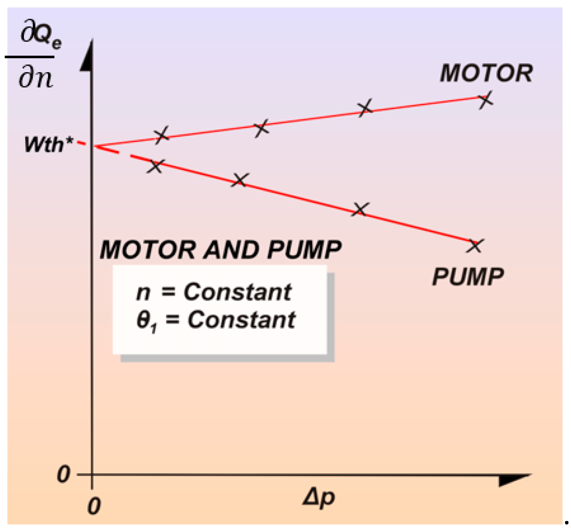
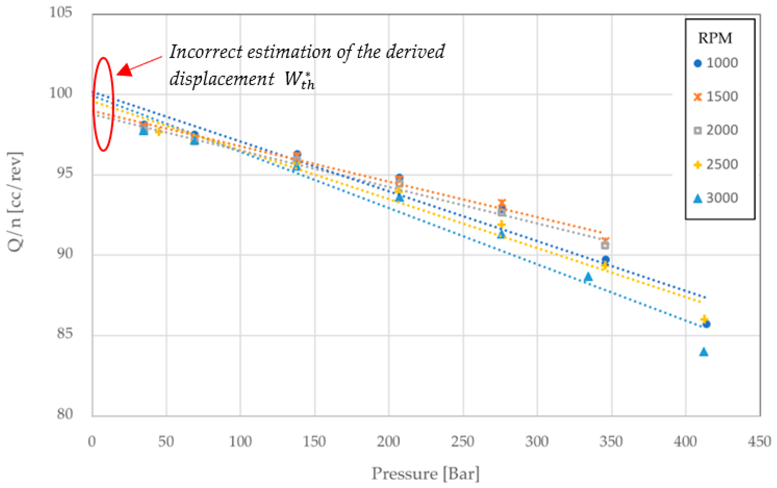
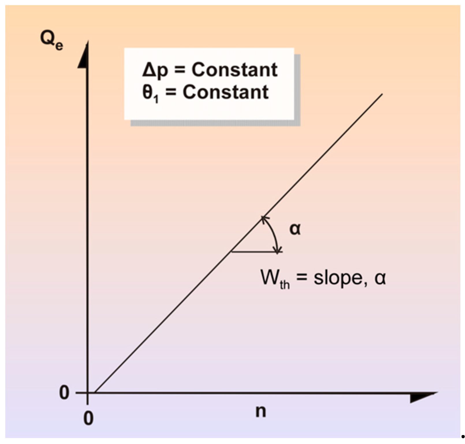
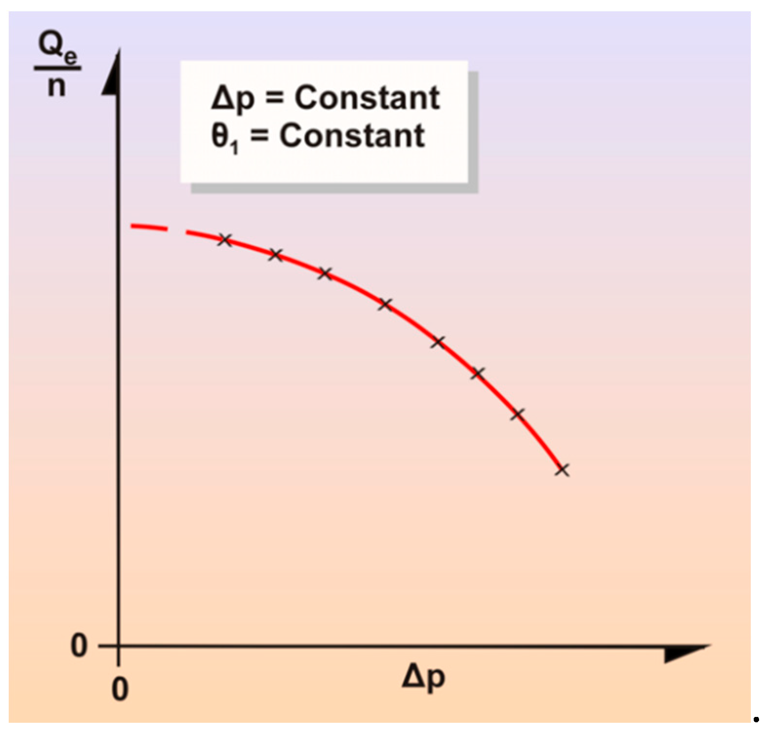
1.1. Illustrative Graphical Example of the Incorrectly Applied Method

The example is used to point out the most common mistake while interpreting this method for estimating the derived displacement of a positive displacement hydraulic machine. The method described herein was also summarized graphically as a two-step process by Garcia and Nicholson [15]. Specifically, the most common error in the calculation of the derived displacement W t h * using this method is believing that the final value is calculated by obtaining the intercept at zero pressure for the extrapolated data, as is seen in Figure 1. While this method does call for the use of the ratio of the measured flow Q over the shaft speed n (Q/n), this method does not indicate that the intercept of such relationship vs. Δp corresponds to the derived displacement W t h * , as has been incorrectly interpreted. Furthermore, this incorrect interpretation would lead to ambiguity, as different estimations of the displacement would be achieved for each set of data collected at different constant shaft speeds n.

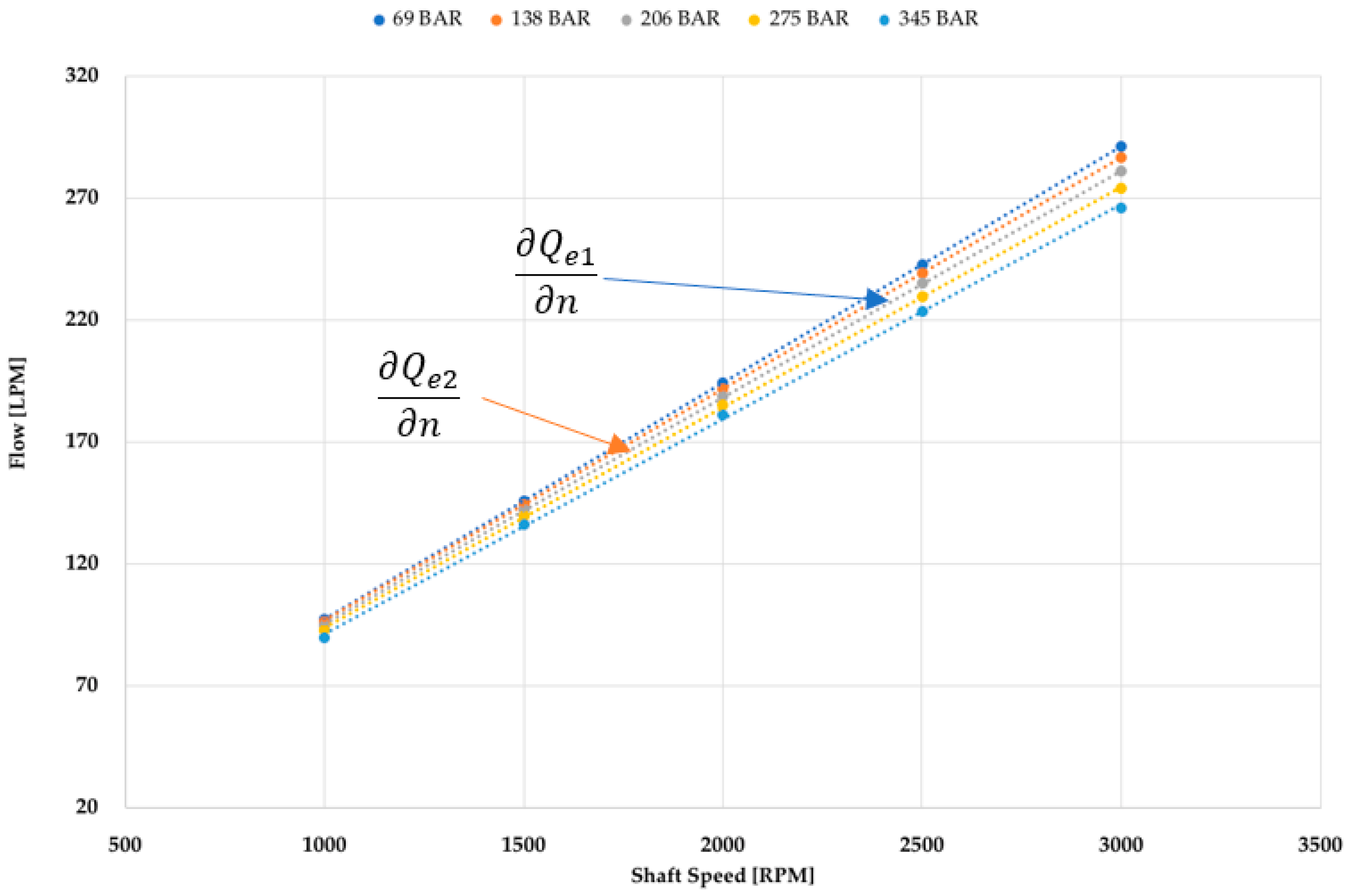
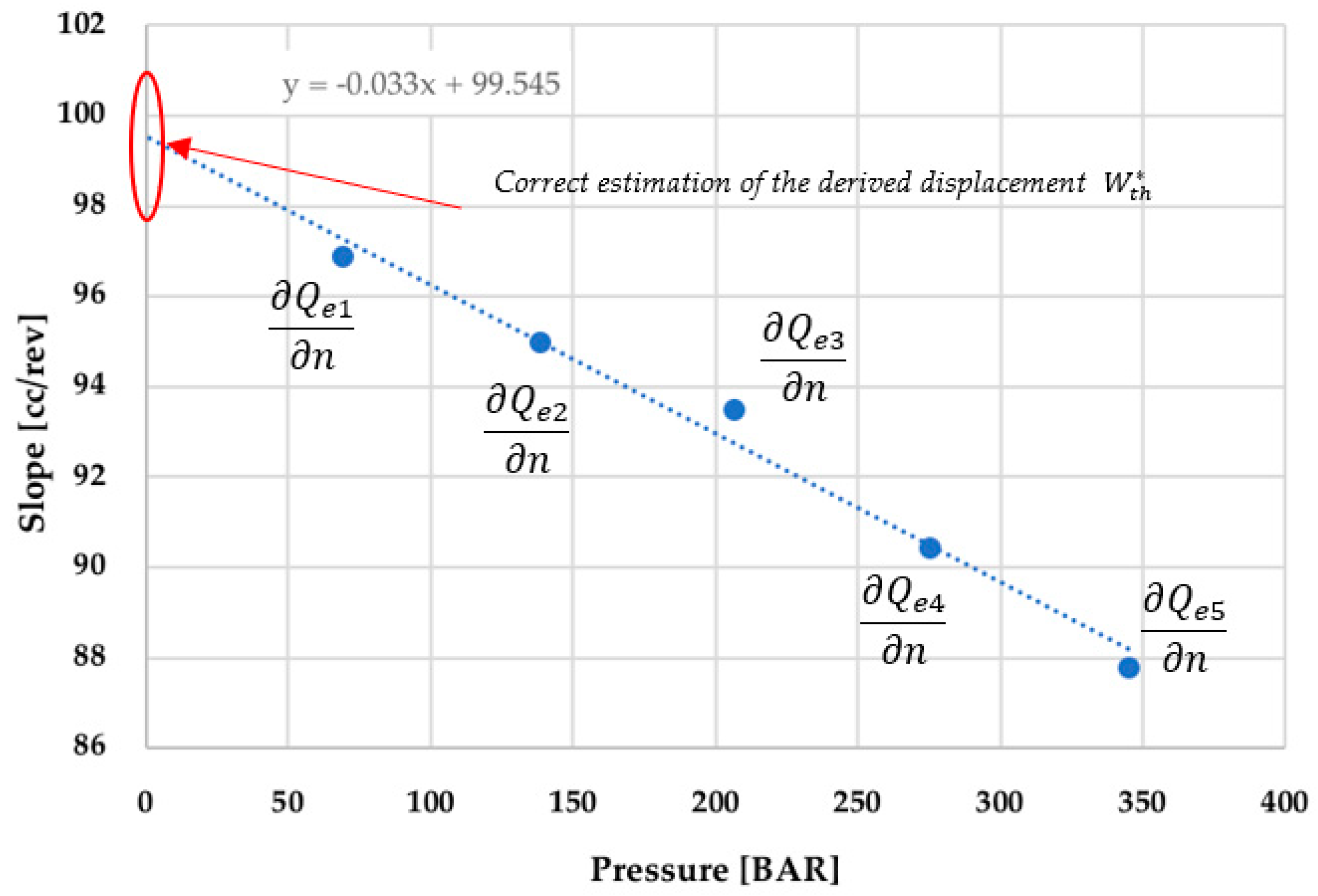
1.2. Graphical Example Illustrating the Correct Method

The correct application of the method calls for the estimation of the slope Q e n of the line produced by the relationship between measured flow Q and the shaft speed n for various pressure levels Δp, as is seen in Figure 2.
The second—and final—step of this process requires the extrapolation of the line formed by the relationship between the slopes Q e i n found in the first step and the various pressure levels Δp. As it is seen in Figure 3, the intercept of this new line with the zero pressure point, corresponds to the correct estimated value of the derived displacement W t h * using the original method from the translated paper.

2. Original Paper—Translated from German

If, in the case of investigations on positive displacement transfer pumps and motors, loss separation methods are used, it is not sufficient to use the geometric displacement volume instead of the theoretical displacement volume. This fact has already been established in [16]. Historically, it was assumed that the displacement of a positive displacement machine was known, and it was the same as the geometric displacement. Even if this view is correct, the displaced volume, so to speak, as determined on the drawing board, does not actually coincide with the measured swept volume. The manufacturing inaccuracies and tolerances cause a statistical spread in the geometric stroke volume, which in many cases is too large for a correct determination of the losses. In 1950, a method for determining the theoretical displacement was published by Wilson [17]. This method consists of the detection of the inclination angle, which results from an assumed linear relationship between the effective volume flow Qe. and the shaft speed n. The theoretical stroke volume is thereby equal to this inclination angle at the lowest possible pressure differential across the displacement unit (Figure 4).
However, because of the kinematic uncertainty of the pumps and motors at low pressures, measurements in this pressure range are difficult, so that the Wilson method does not lead to useful results. In 1957, Schlosser [18] described a method, whereby the theoretical stroke volume uses the definition in Equation (1), and assumed that the pressure difference across the leakage gaps is zero (as seen in Figure 5).
W t h = ( Q e n ) Δ p = 0
The proposed method following this introductory section, in fact, requires an extrapolation from the linear regression, but specifically calls for this relationship to be considered between the rate of change of the effective flow with respect to the change in shaft speed W t h = Q e n at various measured values of the pressure Δ p .
Because of the uncertainty of the stroke volume with small pressure differences, the same objections apply here as in the Wilson method. Furthermore, extrapolating the value of Qe/n at Δp = 0 is not easy, since the curve to be used is not linear. Another disadvantage of this method is the fact the speed at which the Qe/n vs. Δp dependency is to be determined should be very close to zero. If not, the pressure will be too high, causing excessive internal leakage losses.
In 1963, Schlosser and Hilbrands [19] found, by means of measurements, that the slope of Qe vs. n diagram is dependent on the pressure differential Δp. From their technical paper, it is possible to derive a definition of the theoretical displacement volume:
W t h ( Δ Q e Δ n ) Δ p 0 ,   θ 1 ,
This definition means that theoretical displacement is dependent on temperature and pressure. In addition, this paper takes into account the so-called Couette component, with the influence of the rotational speed on the stroke volume. It is clear from this that the actual displacement volume not only depends on the geometry of the positive displacement machine, but is also determined by non-changing displacement effects, such as the Couette component (note that this component is dependent on viscosity and relative speed). It should also be borne in mind that these additional influences play an insignificant role in pumps and motors with comparatively great losses (low efficiencies), and they do not jeopardize the small degrees of separation between the calculated volumetric and mechanical efficiencies [18]. In pumps and motors with very high efficiencies, however, these influences are clearly detectable, but only when flow measurement is performed with sufficient accuracy. These influences must not be neglected when an exact loss separation is required. Such separation demands a precisely known value for the displacement. Therefore, a method for the determination of the theoretical displacement volume based on volumetric flow measurements in pumps and motors will be described next, which allows an accurate assessment of the volumetric and mechanical efficiencies.
Therefore, a method for the determination of the theoretical displacement volume is to be described, which is based on volumetric measurements on positive displacement pumps and motors, which in turn, allows an accurate detection of the partial losses.

3. Determination of the Stroke Volume

3.1. Critique of a Common Definition of Wth

The following equations are used as the starting point [16]:
Q t h = n   W t h
and:
Q t h = Q e ± Q s
The plus sign applies to a pump while the minus sign is for a motor. Qe is defined as follows:
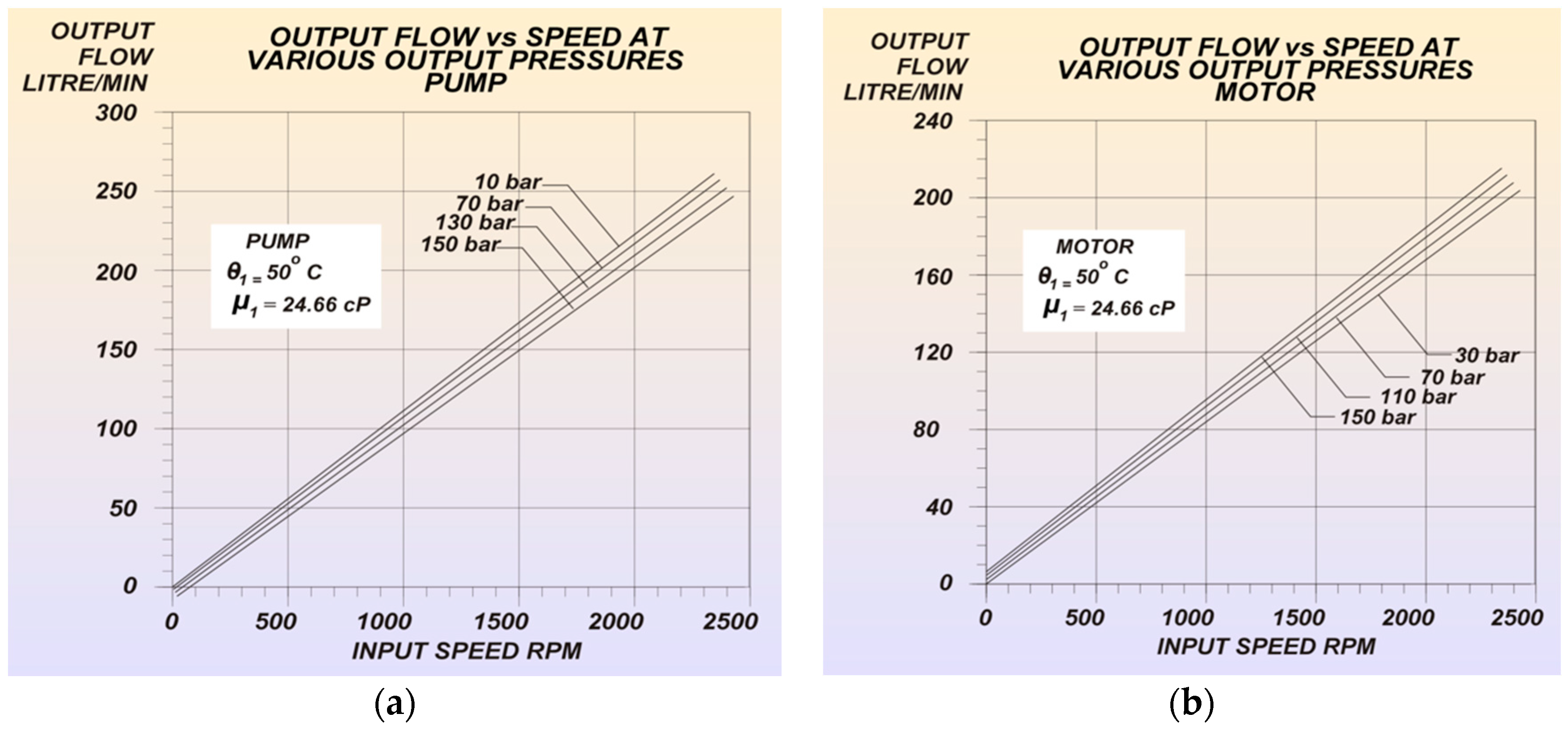
  • For pumps: Qe is the volume flow available at the outlet port calculated at the outlet pressure but using the fluid temperature at the inlet port (Figure 6b);
  • For motors: Qe is the volume flow delivered to the inlet port calculated at the inlet pressure and uses the fluid temperature at the inlet port (Figure 6a).
In general, the pressure at the inlet port of a pump, or the outlet pressure of a motor, will be at or near atmospheric pressure. The consequence of the assertions made above is that all the contributors are non-transient displacement effects, such as compressibility and expansion in effective volume flow. For a given hydraulic oil, the following apply:
W t h = f ( Δ p ,   n ,   θ 1 ) ,
and:
Q s = g ( Δ p ,   n ,   θ 1 ) ,
The only directly measurable variables are Q e , Δ p ,   n ,   θ 1 . From the definition in Equation (2) in the introduction, and combining it with Equations (3) and (4), a new expression can be found:
Q e n = ( ( n W t h ± Q s ) n ) Δ p , θ 1 = ( W t h ) Δ p , θ 1 + n ( W t h n ) Δ p , θ 1 ± ( Q s n ) Δ p , θ 1 ,
The plus sign applies to a motor and the minus sign applies to a pump. Equation (7) can be evaluated for Wth only if:
n ( W t h n ) Δ p , θ 1 ± ( Q s n ) Δ p , θ 1 = 0 ,
This is a requirement that is generally not met. Furthermore, this inequality applies in general:
( Δ Q e Δ n ) Δ p , θ 1 ( Q e n ) Δ p , θ 1 ,
An assumption is made that there is a linear relationship between speed and flow, stated below in Equation (10), but it must be investigated with further research. For this reason, the original author considered Equation (2) to be incorrect. It is therefore necessary to analyze the structure of the components of the measurable effective volume flow more precisely. Figure 7 represents the aforementioned relationship.

3.2. A Critical Analysis of the Effective Volume Flow

The effective volume flow through an averaging unit with a pressure difference Δ p at an inlet temperature θ 1 and for a particular hydraulic oil consists of four components. These components correspond to (a) a displacement portion, (b) a Couette component, (c) a leakage component, and (d) an expansion/compression component. These four components will be individually discussed below.

3.2.1. The Positive Displacement Component

The positive displacement component, Qg, is:
Q g = n ( W g   ( Δ p = 0 ,   θ 1 ) + K 1 Δ p W g ( Δ p = 0 ,   θ 1 ) )
where Wg is the geometric displacement [16] and the expression, K 1 Δ p W g   ( Δ p = 0 ,   θ 1 ) is the enlargement or reduction of the geometric displacement by the pressure difference, often referred to as the compressibility component. This influence is assumed to be linear with the pressure difference.

3.2.2. The Couette Component

The speed dependent, i.e., Couette component, is caused by the relative velocities between two surfaces, which act on and drag along a speed-dependent, viscous fluid:
Q m = n ( W m   ( Δ p = 0 ,   θ 1 ) + K 2 Δ p W m   ( Δ p = 0 ,   θ 1 ) ) ,
In this case, Wm identifies the Couette volume per revolution. The expression K 2 Δ p W m   ( Δ p = 0 ,   θ 1 ) gives the increase or the decrease of this volume by the pressure difference Δp. This influence will also be assumed to be linear with the pressure difference.

3.2.3. The Leakage Component

The leakage component is denoted as Qs.

3.2.4. The Compressibility Component

The expansion of the effectively occurring volumetric flow must be taken into account, since the volumetric flow is related to the pressure at the low pressure side of the displacement pump or motor. The expansion component at a certain pressure difference Δp at a temperature θ1 can be approximately described with the help of the expression:
ϱ o ϱ = ( 1 + A p B p 2 + C p 3 ) θ 1 ,
Let the expansion component at a certain pressure difference Δp under a temperature θ1 be approximated by [18] and [20]:
Q e x p = n ( W g ( Δ p = 0 ) , θ 1 + W m ( Δ p = 0 ) , θ 1 ± Q s ) ( A p B p 2 + C p 3 ) θ 1
The assumption here is that there is approximate atmospheric pressure at the low pressure side. The compressibility flow, Qexp, can be simplified with the following assumptions:
-
The pressure at the low pressure side is close to atmospheric pressure;
-
The contribution of the Couette flow and leakage effect is negligibly small;
-
Consequently, by disregarding the very small contribution of the Couette and leakage current influences, the parenthetical in Equation (13) can be reduced, and the expansion rate is:
Q e x p = n ( W g ( Δ p = 0 ) , θ 1 ) ( A ( Δ p B ( Δ p ) 2 + C ( Δ p ) 3 ) θ 1 ,
The following additional comments apply to the four components above:
-
The constants K1 and K2 are known to be positive or negative;
-
The values of A, B, and C are only dependent on the temperature θ 1 [20];
-
All relationships apply to the temperature, θ 1 , on the inlet side.
The equation for the effective volume flow at a pressure difference Δp and a temperature θ 1 is now:
Q e = n ( W g ( Δ p = 0 ) , θ 1 + K 1 Δ p W g   ( Δ p = 0 ,   θ 1 ) ) + n ( W m   ( Δ p = 0 ,   θ 1 ) + K 2 Δ p W m   ( Δ p = 0 ,   θ 1 ) ) ± Q s + n ( W g ( Δ p = 0 ) , θ 1 ) ( A ( Δ p B ( Δ p ) 2 + C ( Δ p ) 3 )
Thus, it becomes:
Q e n = W g ( Δ p = 0 ) , θ 1 + K 1 Δ p W g   ( Δ p = 0 ,   θ 1 ) + n ( ( W g ( Δ p = 0 ) , θ 1 + K 1 Δ p W g   ( Δ p = 0 ,   θ 1 ) ) n ) Δ p ,   θ 1 + Q s n + W m ( Δ p = 0 ) , θ 1 + K 2 Δ p W m ( Δ p = 0 ,   θ 1 ) + n ( ( W m ( Δ p = 0 ) , θ 1 + K 2 Δ p W m ( Δ p = 0 ,   θ 1 ) ) n ) Δ p ,   θ 1 + n ( W g ( Δ p = 0 ) , θ 1 ) ( A ( Δ p B ( Δ p ) 2 + C ( Δ p ) 3 ) + n ( W g ( Δ p = 0 ) , θ 1 n ) + n ( W g ( Δ p = 0 ) , θ 1 ) ( A ( Δ p B ( Δ p ) 2 + C ( Δ p ) 3 ) θ 1
This provides a relationship on which a new definition of theoretical displacement can be based. Now it can be stated:
( W g n ) Δ p , θ 1 = 0   a n d   ( W m n ) Δ p , θ 1 = 0
The influence of the shaft speed on the displacement and Couette volume (e.g., as a result of centrifugal force) is negligibly small, so that this assumption for practical pumps and motors is justified. First and foremost, positive displacement pumps and motors are influenced by the presence of pressure distributions in the internal gaps and clearances. The resulting forces are from a multiplicity of force types, all derived from pressure field forces existing in flow passages and clearances. For this reason, an impact on Wg by filling losses in pumps must be avoided by suitably setting up the test unit and test equipment when carrying out loss-separation measurements. Filling losses (cavitation) can result in irreversible damage to the test unit. The effective volume flow Qe can be expressed in a simplified way:
( Q e n ) Δ p , θ 1 = W g ( Δ p = 0 ) , θ 1 + K 1 Δ p W g   ( Δ p = 0 ,   θ 1 ) ± ( Q s n ) Δ p , θ 1 + W m ( Δ p = 0 ) , θ 1        + K 2 Δ p W m   ( Δ p = 0 ,   θ 1 ) + n ( W g ( Δ p = 0 ) , θ 1 ) ( A ( Δ p B ( Δ p ) 2 + C ( Δ p ) 3 ) θ 1
From many measurements on displacement pumps and motors, it has become clear that the rate of change of Qe is linear with speed, n, therefore the slope of the flow is not dependent on the speed:
( Q e n ) Δ p , θ 1 h ( n )
The derivative function is independent of the speed (Figure 6a,b). For this purpose, the correlation coefficients were calculated for the linear assumptions in Qe vs. n. Based on measurement results from about 200 pumps and motors of known types, it can be reported that the correlation coefficients are very close to a value of 1 using the linear assumption. From this, one can conclude that the partial derivative of Qe vs. n is independent of the speed, n, within the accuracy of the flow and speed measurements. Compared with the effects:
Q s n = 0
Of the rest of the influences on flow, one may draw the same conclusion regarding leakage flow, Qs vs. n. Furthermore, if Δp = 0, then the leakage flow is zero, regardless of the speed [16].
It also follows from Equations (18) and (20) that:
Q e n = W g ( Δ p = 0 ) , θ 1 + W m ( Δ p = 0 ) , θ 1
If one considers Q e n as a function of Δp, with θ1 to be more or less constant at the same time, the relationship shown in Figure 7a,b seems to be generally representative of positive displacement pumps and motors. Accordingly, Q e n can be found from measurements.

4. Proposal for a New, Final Definition of the Theoretical Displacement

On the basis of the preceding consideration, after introduction of:
( Q e n ) ( Δ p = 0 ) , θ 1 W t h *
From Equation (21), a new definition of the theoretical stroke volume is proposed:
W t h * = W g ( Δ p = 0 ) , θ 1 + W m ( Δ p = 0 ) , θ 1
The theoretical displacement volume W t h * is thus composed of both the geometric displacement and the Couette volume, based on conditions where Δp = 0 at a certain inlet temperature, θ1. The following comments are to be made about the theoretical displacement volume defined in this way:
  • W t h ( Δ p = 0 ) , θ 1 is independent of n and Δp;
  • As a result of the definition of W t h * , it is unavoidable that all influencing effects on the volumetric flow, which are not expressed by W g ( Δ p = 0 ) , θ 1 , and W m ( Δ p = 0 ) , θ 1 , can contribute to the amount of the leakage flow, Qs;
  • At present, no methods for the separation of Wg and Wm are known;
  • Among other things, the cause of the repeated occurrence of volumetric efficiencies greater than 100% must be sought in the application of Wg as the theoretical displacement volume, ignoring the entrainment volume Wm. This excess volumetric efficiency effect occurs especially in pumps with high volumetric efficiencies;
  • Pumps and motors with a mathematically very precise determinable geometric displacement, where a Couette volume is absent or negligible, show values for W g ( Δ p = 0 ) , θ 1 that are very close to W t h * , provided that θ1 is the same. Measurements have shown that this is the case with screw pumps and motors [21].

5. Differences between W t h * and the Earlier Method

  • The theoretical displacement based on the definition from Equation (2) is repeated here for convenience:
    W t h ( Δ Q e Δ n ) Δ p 0 ,   θ 1
    Apart from Δp, the effective flow is also dependent on the influence of the speed on the leakage flow. The derived displacement volume W t h * is thus dependent on the shape of the leakage clearances, the internal resistance, and the properties of the fluid.
  • The method of determining W t h leaves the choice of Δp much leeway. In the determination of W t h , this freedom is no longer present, since W t h * is determined for values with Δp = 0, where Δpi should be small.

6. The Practical Implementation of the Method

At a constant inlet temperature θ1 and a pressure difference, Δp, the effective volume flow, Qe, is measured from the displacement pump for at least five values of n. The results can still be ordered: Qe1, n1, Qe2, n2, Qe3, n3, etc.
This measurement has to be done once again using at least five different pressure values Δp1, Δp2 Δp3, …. The relations Qe vs. n for Δp = constant and θ1 = constant can now be determined, for example, with the method of least squares. One finds in this way:
Q e ( Δ p 1 ) = a 1 n + b 1 ,
And for other terms:
Q e ( Δ p 2 ) = a 2 n + b 2 ,   etc .
where a and b depend on Δp and θ1. An example of this is displayed in the diagrams obtained from measurement results in Figure 8a,b below.
In addition, it can be calculated with which correlation coefficients these equations describe the measured relationship. The correlation coefficient is defined as follows:
C o r r . C o e f f = [ ( n i n ¯ ) ( Q e i Q e ¯ ) ] ( n n ¯ ) 2 + ( Q e i Q e ¯ ) 2 ,
For all types of positive displacement pumps and motors measured in the Technical University of Eindhoven Laboratory for Hydraulic Transmissions, these correlation coefficients appear to be very close to unity. From the values a1, a2, a3 …, the relation a = c Δp + d can now be determined in the same way. The value of d indicates how large Wth is at the temperature selected as the inlet temperature θ1 for the measurement. Also, the degree of correlation determines whether there is a justification for assuming a linear relationship between a and Δp. For correlation coefficients < 0.90, nonlinear fitting is recommended in most cases.
A practical determination of W t h * using the method described above is shown in Figure 9a–e. This is a measurement on an axial piston motor.
Furthermore, the application of the method described above and the use of the measuring apparatus according to [22] have shown that in the case of displacement units that can be measured as a pump and motor, W t h * m and W t h * P are the same or almost the same for the same values of θ1, as seen in Figure 10.
For this purpose, measurements were made on positive displacement pumps and motors of different types, such as axial piston, radial piston, and screw units. For axial piston units very small differences were found, where:
W t h θ 1 * m W t h θ 1 * P 0.5 ( W t h θ 1 * m + W t h θ 1 * P ) · 100 % < 0.05 %

7. Original Conclusions from Translated Paper

With the new method for determining the theoretical stroke volume described here, very good results have already been achieved, together with improved measuring techniques. From these results, among others, the fact that volumetric efficiencies above 100% are common in measuring high-quality piston pumps and motors is not always the result of measurement inaccuracies. Often the cause of this is a misinterpretation of the measurement results. For the determination of Wth, the measurement inaccuracy may be among the most notable. For volumetric flow measurements, the error may certainly not be greater than ± 0.5% of the measured value. The size of the effects that are shown with this new method are generally 4% to 8% of the volume flow.

8. End of the Translated Document

On the basis of the observations made, it is appropriate to examine whether the Comité Européen des Transmissions Oléohydrauliques et Pneumatiques (CETOP) definition [14] and ISO 8426 standard should be subject to change. At the same time, it has to be determined which test stand and test equipment are suitable for this new method.

Author Contributions

Authors Contributions to the Revised, Translated and Expanded Document: As stated in the introduction section, this paper is the result of translating the original paper from 1970, written in the German language, to English; the original paper [1] was by the author G.T. (Retired), Eindhoven University of Technology. He was assisted by three volunteers from the United States, J.J., Fluid Power Institute Director (Retired), Milwaukee School of Engineering, J.M., Mechanical Engineer, Bosch-Rexroth (Retired), and K.T., Bosch-Rexroth; they carried out the translation of the original document, and brought to the project about 200 years of industrial and academic experience in hydraulic fluid power. J.G.-B. contributed to the introduction section with examples of incorrect uses of the method and the need for this translation, and provided extensive editing of the document and its formatting to be acceptable for publication. He also provided a typical illustrative example of the incorrect interpretation of the method. G.T., being the original author, and having fluency in both German and English, as well as in his native Dutch, was the final arbiter of the translated text. He reviewed the translation and approved the final copy. J.J. provided additional editing by removing most equations from in-line text locations to type-set and numbered equations so they could be properly referred to in the appropriate places in the text, and he also redrew all of the figures. Technology, both artificial intelligence and the near instantaneous response of the internet, made this project eminently doable in a matter of a few weeks. The result is an English version of a paper with almost classical connotations that carries the original intent and nuance of the principal author, G.T., and a dedicated volunteer team. This English version has a decided USA “accent”, and is felt to be technically equivalent to, and compatible with, the German original.

Funding

This project revision received no external funding.

Conflicts of Interest

The authors declare no conflict of interest.

Nomenclature

SymbolDescriptionDimensionsSymbolDescriptionDimensions
nShaft speedT−1 W t h * P Derived displacement for a pumpL3
ΔpPressure differential between high and low sidesM L−1T−2 W t h * M Derived displacement for a motorL3
QgGeometric volumetric flowL3T−1aConstant in the Qe vs. n relationshipL3
QeEffective volumetric flowL3T−1bConstant in the Qe vs. n relationshipL3T−1
QsLeakage flowL3T−1cConstant in the ∂Qe/∂n vs. Δp relationshipM−1 L4T2
QexpCompressibility flowL3T−1dConstant in the ∂Qe/∂n vs. Δp relationshipL3
QThTheoretical/ ideal flowL3T−1θ1Inlet temperature°C
WthDerived displacementL3 ϱ Fluid density at pressure p and temperature θ1M L−3
WgGeometric displacementL3 ϱ o Fluid density at standard conditionsM L−3
WmCouette volumeL3ATemperature dependent factor in the state equationM−1 LT−2
W t h * Derived displacement from measurementsL3BTemperature dependent factor in the state equationM−2 L2T4
K1Bulk modulus for geometric stroke volumeM L−1T−2CTemperature dependent factor in the state equationM−2 L3T6
K2Bulk modulus for fluid volumeM L−1T−2

References

  1. Toet, G. Die Bestimmung des theoretischen Hubvolumens von hydrostatischen Verdrangerpumpen und Motoren aus volumetrischen Messungen. Olhydraulik Pneum. 1970, 14, 185–190. [Google Scholar]
  2. Post, W.J.A.E.M. Models for steady-state performance of hydraulic pumps: Determination of displacement. In Proceedings of the 9th International Workshop, Bath, UK, 9–11 September 1996. [Google Scholar]
  3. Conrad, F.; Trostmann, E.; Zhang, M. Experimental identification and modelling of flow and torque losses in gerotor hydraulic motors. Jpn. Fluid Power Syst. Soc. 1993, 1993, 677–682. [Google Scholar] [CrossRef] [Green Version]
  4. Ivantysyn, J.; Ivantysynova, M. Hydrostatic Pumps and Motors, Principles, Designs, Performance, Modeling, Analysis, Control and Testing; Academia Books International: New Delhi, India, 2000. [Google Scholar]
  5. International Organization for Standardization (ISO). Hydraulic Fluid Power—Positive Displacement Pumps and Motors—Determination of Derived Capacity; ISO Copyright Office: Geneva, Switzerland, 2008. [Google Scholar]
  6. SAE. Hydraulic Power Pump Test Procedure. J745 (Recommended Practice). In SAE Handbook; Society of Automotive Engineers: Warrendale, PA, USA, 1991. [Google Scholar]
  7. Hall, S. Statistical Analysis of Multiple Hydrostatic Pump Flow Loss Models. Master’s Thesis, Iowa State University, Ames, IA, USA, 2014. [Google Scholar]
  8. Myszkowski, A. Energy analysis of an ideal suction-pressure unit. Arch. Mech. Technol. Mater. 2015, 35, 51–60. [Google Scholar]
  9. Czyński, M. Energy efficiency of hydrostatic transmission. Comparing results of laboratory and simulation tests. Sci. Probl. Mach. Oper. Maint. 2008, 43, 59–70. [Google Scholar]
  10. Taeho, K.; Kalbfleisch, P.; Ivantysynova, M. The effect of cross porting on derived displacement volume. Int. J. Fluid Power 2014, 15, 77–85. [Google Scholar]
  11. Zecchi, M.; Mehdizadeh, A.; Ivantysynova, M. A novel approach to predict the steady state temperature in ports and case of swash plate type axial piston machines. In Proceedings of the 13th Scandinavian International Conference on Fluid Power, Linköping, Sweden, 3–5 June 2013; Linköping University Electronic Press: Linköping, Sweden, 2013; pp. 177–187. [Google Scholar]
  12. Manring, N.; Christopher, W. Calculating the Mechanical and Volumetric Efficiencies for Check-Valve Type, Digital Displacement Pumps. In Proceedings of the BATH/ASME 2018 Symposium on Fluid Power and Motion Control, Bath, UK, 12–14 September 2018. [Google Scholar]
  13. Noah, M.; Williamson, C. The Theoretical Volumetric Displacement of a Check-Valve Type, Digital Displacement Pump. J. Dyn. Syst. Meas. Control 2019, 141, 031014. [Google Scholar]
  14. Kohmäscher, T.; Rahmfeld, R.; Murrenhoff, H.; Skirde, E. Improved loss modeling of hydrostatic units: Requirement for precise simulation of mobile working machine drivelines. In Proceedings of the ASME 2007 International Mechanical Engineering Congress and Exposition, Seattle, WA, USA, 11–15 November 2007; pp. 195–206. [Google Scholar]
  15. Garcia-Bravo, J.; Nicholson, J. What is the real size of that pump? Fluid Power J. Manuf. Dir. 2018, 25, 20–21. [Google Scholar]
  16. Schlosser, W.M.J.; Hilbrands, J.W. Das volumetrische Wirkungsgrad von Verdrongerpumpen. Oilhydraulik Pneum. 1963, 7, 469–476. [Google Scholar]
  17. Wilson, W.E. Positive Displacement Pumps and Fluid Motors; Publication Corporation: New York, NY, USA, 1950. [Google Scholar]
  18. Schlosser, W.M.J. Meten aan Verdringerpompen. Ph.D. Thesis, Technical Hogeschool Delft, Delft, The Netherlands, 1957. [Google Scholar]
  19. Schlosser, W.M.J.; Hilbrands, J.W. Das theoretische Hubvolumen von Verdrangerpumpen. Olhydraulik Pneum. 1963, 7, 133–138. [Google Scholar]
  20. Schlosser, W.M.J.; Verduyn, H.A. Folgerungen aus einer Zustandsgleichung fur Mineralole. Olhydraulik Pneum. 1960, 2, 39–41. [Google Scholar]
  21. Van der Kroonenberg, H.H. Het Meten en Verkloren of de Karakferistieken van a Hydrostatische Wormmotor. Ph.D. Thesis, TH Eindhoven, Eindhoven, The Netherlands, 1966. [Google Scholar]
  22. Schlosser, W.M.J.; Toet, G. Messung stationärer Eigenschaften von hydraulischen Übertragungen. Schweiz. Bauzeilung 1969, 87, 167–175. [Google Scholar]
Figure 1. Incorrect interpretation of the method presented in this document.
Energies 12 00415 g001
Figure 2. First step for estimating the derived displacement using this method.
Energies 12 00415 g002
Figure 3. Second step for estimating the derived displacement using this method.
Energies 12 00415 g003
Figure 4. The linear interrelationship between the effective flow Qe of a positive displacement machine and the shaft speed n.
Energies 12 00415 g004
Figure 5. The piston displacement Wth = Qe/n vs. the pressure difference Δp.
Energies 12 00415 g005
Figure 6. Volumetric flow vs. shaft speed for (a) a positive displacement motor and (b) a positive displacement pump.
Energies 12 00415 g006
Figure 7. The ∂Qe/n vs. the pressure difference, Δp, for (a) a positive displacement pump and (b) a positive displacement motor.
Energies 12 00415 g007
Figure 8. The effective volume flow, Qe, vs. the shaft speed, n, for different pressure differences, Δp, at constant temperature and fluid viscosity for a positive displacement (a) pump and (b) motor.
Energies 12 00415 g008
Figure 9. Determination of theoretical displacement, W t h * , and axial piston motor at (a) 35 °C, (b) 41 °C, (c) 50 °C, (d) 56 °C, and (e) 67 °C.
Energies 12 00415 g009aEnergies 12 00415 g009b
Figure 10. The Q e n vs. the pressure difference, Δp, for a positive displacement pump and motor.
Energies 12 00415 g010

