Development of Complex Energy Systems with Absorption Technology by Combining Elementary Processes


1
Department of Applied Mechanics, Waseda University, Tokyo 162-0044, Japan
2
Waseda Research Institute for Science and Engineering, Tokyo 162-0044, Japan
3
Advanced Collaborative Research Organization for Smart Society, Tokyo 162-0044, Japan
*
Author to whom correspondence should be addressed.
Energies 2019, 12(3), 495; https://doi.org/10.3390/en12030495
Submission received: 27 December 2018
/
Revised: 31 January 2019
/
Accepted: 2 February 2019
/
Published: 4 February 2019
(This article belongs to the Special Issue Optimum Choice of Energy System Configuration and Storages for a Proper Match between Energy Conversion and Demands)
Abstract
:Optimal design of energy systems ultimately aims to develop a methodology to realize an energy system that utilizes available resources to generate maximum product with minimum components. For this aim, several researches attempt to decide the optimal system configuration as a problem of decomposing each energy system into primitive process elements. Then, they search the optimal combination sequentially from the minimum number of constituent elements. This paper proposes a bottom-up procedure to define and explore configurations by combining elementary processes for energy systems with absorption technology, which is widely applied as a heat driven technology and important for improving system’s energy efficiency and utilizing alternative energy resources. Two examples of application are presented to show the capability of the proposed methodology to find basic configurations that can generate the maximum product. The demonstration shows that the existing absorption systems, which would be calculated based on the experience of designers, could be derived by performing optimization with the synthesis methodology automatically under the simplified/idealized operating conditions. The proposed bottom-up methodology is significant for realizing an optimized absorption system. With this methodology, engineers will be able to predict all possible configurations and identify a simple yet feasible optimal system configuration.
1. Introduction
Recently, in the design of smart cities, etc., it is necessary to derive an optimum system capable of supplying energy satisfying the required specifications while effectively utilizing resources such as renewable or unused waste heat. Optimization for energy systems is performed at three stages: synthesis (configuration), implying the definition of set of components and their interconnections; design (component characteristics), implying the definition of technical specifications of each component and the properties of the working fluids at nominal load; and, operation, implying the definition of operating properties of the working fluid under specified conditions [1]. In particular, the fundamental research on the synthesis/design optimization methodology of energy conversion systems is extremely difficult because there are too many parameters to be considered. Most of the optimization problems are solved using a superstructure prepared by the designer in advance and a pruning strategy for the search process leading to the definition of the optimal configuration [2,3,4]. In addition to this, research groups have also developed superstructure-free methodologies [5,6,7,8] that start from an existing system configuration and add/remove parts of it using evolutionary algorithms to define new design alternatives. However, these approaches have some disadvantages: first, the definition of superstructure is still based on the designer’s experience or the starting solution and limits the search space; and, second, the optimal solution sometimes would be too complex and infeasible.
In general, the more complex a system configuration, the more ideal efficiency improvement and product increase can be expected according to the given thermodynamic conditions. However, from the economic point of view, a strategy to design a system that can generate the utmost utility while being a minimum component is necessary. Therefore, the ultimate goal in the optimal design of energy systems is to construct the methodology to realize an energy system that utilizes available resources to maximize the utility with minimum components. For the goal, it is appropriate to decide the optimal system configuration as a problem of decomposing the energy system into primitive process elements and searching the optimal combination sequentially from the minimum number of constituent elements, which is a bottom-up approach. Toffolo and Lazzaretto proposed a general criterion, named SYNTHSEP methodology [9,10,11,12], to generate a complex energy conversion system by combining elementary cycles based on the original idea that the elementary thermodynamic cycle is fundamental to the construction of any energy system configuration. The pioneering SYNTHSEP methodology borrows ideas from the HEATSEP methodology [13,14,15,16], in which designers focus on a set of fundamental thermodynamic processes (compression, heating, expansion, cooling) in the flowsheet—the so-called “basic configuration” of the system. In this basic configuration, heat transfer devices between system components are replaced with “thermal cuts”. All heat transfer processes required for varying the specific enthalpy of working fluid are assumed to occur inside a “black box” of unknown configuration. Design of a heat exchangers network is left to a later process. The SYNTHSEP methodology aims to represent and explore the search space of synthesis/design optimization problems. The basic configurations of energy conversion systems are defined as the combination of the elementary cycles, which are defined as the consequence of four processes (compression, heating, expansion and cooling), obtained by sharing some fundamental processes. With this bottom-up methodology, engineers will be able to predict all possible configurations in advance and identify a simple yet feasible optimal system configuration. The original idea that the basic configuration is defined as a set of elementary cycles can be applied to any types of energy systems, however, the concrete procedure to assemble elementary cycles and to codify and apply the idea to optimization of a system is constructed only for power generation system operating with one pure working fluid so far.
On the other hand, absorption technology is widely applied as a heat driven technology and it is important for improving systems’ energy efficiency and utilizing alternative energy resources such as solar power and low-temperature waste heat. The absorption technology-aid system is an energy system operating with mixture and including some absorption and generation processes and the benefits include using significantly less electricity. An absorption power and cooling system can be mentioned as a representative one. A mixed refrigerant cycle for power production and cooling was proposed by Goswami [17]; it combines a Rankine cycle and a refrigeration cycle using absorption technologies. Xu et. al. performed a parametric study for the proposed absorption power and cooling system and proved that the system could be optimized to produce maximum power, refrigeration capacity, and system efficiency [18]. Martin and Goswami also carried out a theoretical and experimental study of the Goswami cycle [19]. The absorption power and cooling system, which attempts to generate both heating/refrigeration capacity and a net power output, sometimes requires the superheating and sub-cooling capabilities of working fluids. Fontalvo et al. performed an exergy analysis for the power and cooling system operating with an ammonia-water mixture and demonstrated the importance of superheater for exergy efficiency of the overall system [20]. The absorption refrigerator, which runs on a heat source instead of electric power, is also a widely used absorption technology. Herold et. al. suggested expressing an absorption refrigeration system as the combination of power generation and refrigeration cycles [21]. The main difference between an absorption refrigerator/heat pump and an absorption power and cooling system is that the former does not require a net power output to function. Examples of the absorption technologies include systems utilizing solar, geothermal, and biomass energy, and engine waste heat recovery [22,23,24,25]. Many researchers have attempted to perform optimization on the absorption refrigeration system, e.g., the entropy generation minimization methodology was introduced for designing optimal real devices [26] and Myat et al. demonstrated that minimizing the entropy generated in an absorption refrigeration system leads to the maximization of its coefficient of performance (COP) [27]. Moreover, in order to improve the COP of a system driven by low temperatures, several studies have attempted to change the cycle configurations. Such modified cycles include absorber heat exchanger (AHX) cycle [28] and generator absorber heat exchanger cycle [21], which uses absorption heat to increase generator temperature. However, these studies on the optimization of cycle configuration are only parametric or heuristic, whereas the design solutions are still dependent on experience of designers. To derive the optimal design solution from all possible system candidates, a general procedure to search cycle configurations of the absorption refrigeration system is necessary. Ziegler and Alefeld proposed a procedure to define the cycle configurations for absorption refrigeration system [29,30]. An absorption refrigeration system configuration is defined as the combination of elementary refrigeration cycles and elementary heat transformer cycles. Based on this methodology, Inoue presented a simplified analysis to decide optimal the number of generation processes in an absorption refrigerator for a specific heat-source temperature [31]. However, these methodologies could not guarantee that the absorption refrigerator is the optimal solution among all the possible absorption technology-aided energy systems under specific environmental conditions.
Considering these limitations of previous approaches, this study aims to represent and explore the search space of synthesis/design optimization problems for absorption technology-aided energy systems. The objective of this study is to extend the SYNTHSEP methodology to an absorption technology-aid energy system, which can be a type of power and cooling cycle and operating with different kinds of working fluids and the mixture, and to develop a bottom-up methodology for defining and exploring all possible configurations of the absorption system. This paper, at first, explain the details of the proposed synthesis methodology for absorption system. After that, examples of application are presented to show the capability of the proposed bottom-up methodology to find basic configurations that can generate the maximum product.
2. Bottom-Up Synthesis Methodology
The new methodology aims to generate the basic configuration of the candidate solutions of a synthesis/design optimization problem for an absorption technology-aid system. The proposed methodology derives many ideas from SYNTHSEP to explore the basic configurations, which is defined as a set of elementary thermodynamic cycles [9]. This methodology should be organized and codified so that an optimization algorithm can implement the organized rules to generate new candidate configurations in the optimization problem.
2.1. Main Idea
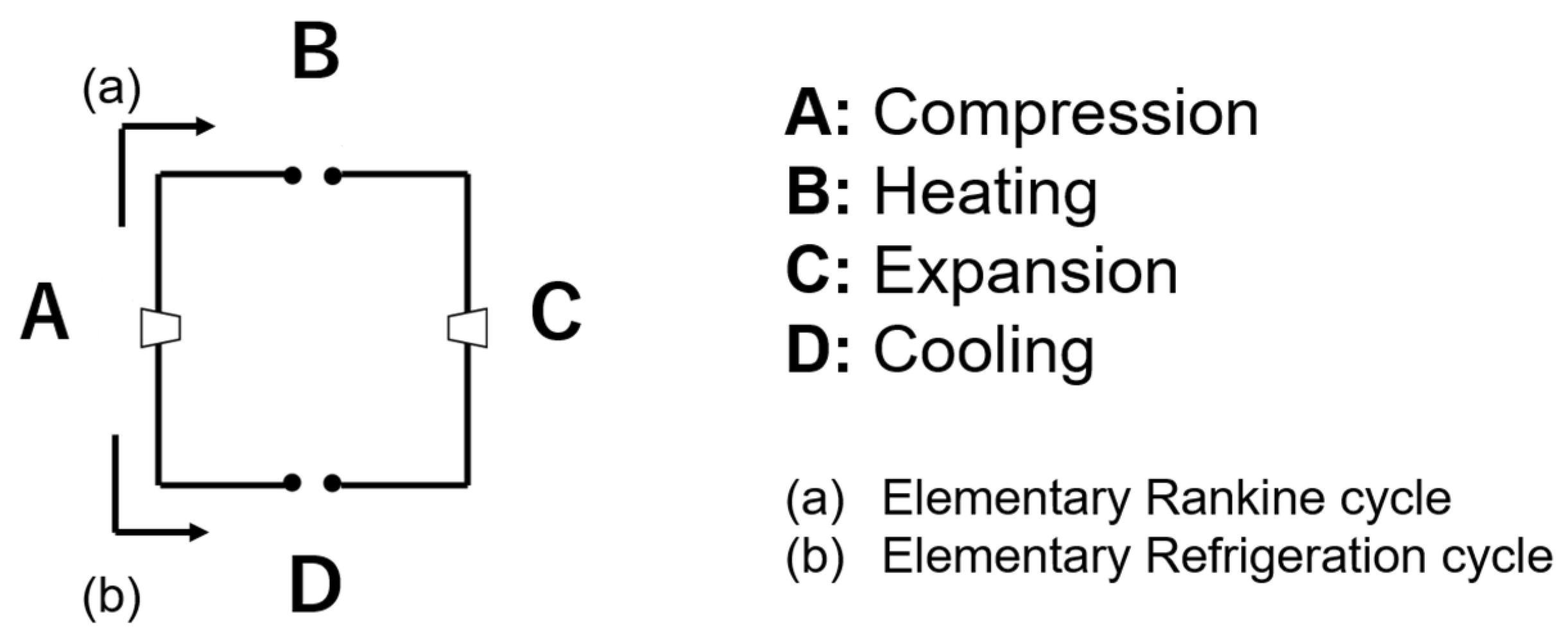
This research proposes a general procedure to define and explore the basic configuration for energy systems with absorption technologies. The basic configuration of energy conversion systems, including the absorption system, could be expressed as the consequence of four fundamental processes: compression (A), heating (B), expansion (C), and cooling (D) [11]. The basic configurations are defined by combining elementary cycles, which are simply expressed as the consequence of the four processes, sharing some of fundamental processes. A process shared by two or more elementary cycles is called “shared process”, while a process operating with a separated working fluid in an elementary cycle is called “non-shared process” in this paper. There are two patterns in the order of the four processes in the elementary cycle: compression, heating, expansion, and cooling in the elementary Rankine cycle; and compression, cooling, expansion, and heating in the elementary Refrigeration cycle as shown in Figure 1. Complex Rankine cycle configurations are defined as a set of the elementary Rankine cycles [11]. On the other hand, the basic configuration of an absorption system, including a type of combined power and cooling cycle, would sometimes be defined by combining both the elementary Rankine cycles and the elementary Refrigeration cycles.
During the assembly of the elementary cycles, mixers and splitters must be introduced to mark the nodes at which the working fluid in the cycles enters a shared process or leaves from a shared process. For absorption system operating with different kinds of working fluid, the working fluid in shared process is a mixture of absorbent solution and refrigerant. Two different working fluids flow into the mixers, and the resulting mixture in liquid state flows out; therefore, the absorption heat must be dissipated to the external environment. Hence, absorbers are located in mixing points and used as mixers. And the absorption process in this study includes not only the mixing and cooling processes in absorbers but also a cooling process to sub-cool the mixed solution at the outlet of absorbers. Therefore, absorption processes are indicated as a sort of placeholders, which are used to leave the temperature/enthalpy of working fluids at the inlet/outlet of the absorption process free to vary. Additionally, to separate the mixture into its constituent working fluids at the splitters, heat is transferred from the external environment to the mixture; therefore, the generators are located in splitting points and used as splitters. Generation process in this study includes not only the heating and splitting process in generators but also a heating process to superheat the refrigerant at the outlet of the generator and a cooling process to sub-cool the solution at the outlet of generators. Therefore, generation processes are indicated as a sort of placeholders, which are used to leave the temperature/enthalpy of working fluids at the inlet/outlet of the generation process free to vary.
Next, in the region in which cycle processes occur, the intensive design parameters are limited by maximum pressure (temperature), minimum pressure (temperature), minimum specific entropy, maximum specific entropy, maximum mass fraction, and minimum mass fraction. The “mass fraction” means the ratio of the mass of a substance to the total mass of mixture according to each working fluid. These values are set according to operational, technological or environmental constraints. The extensive design parameter, indicating mass flow rate, is optimized to find a solution that generate maximum products under the condition of a constant heat source capacity and constraint about the heat transfer feasibility within the undefined heat transfer section.
There are four types of non-shared processes operating with refrigerant: compression, expansion, heating, and cooling, in which the mass fraction and the mass flow rate of refrigerant does not change. In shared processes operating with a mixed solution and non-shared processes operating with an absorbent solution, in this simplified study, it is assumed that the solutions are in their saturated liquid state at all operating nodes and it is assumed that there are only two kinds of processes: compression and expansion. Then, the addition following assumptions are used:
- A solution in its compressed liquid state right after a compression process is heated to be in its saturated liquid state, and this process is considered as a part of compression process in this study.
- A solution right before an expansion process is cooled until the specific entropy of the solution equals that in its saturated liquid state at the outlet of the expansion process, and this process is considered as a part of expansion process in this study.
- Solution heat dissipated is recovered and utilized to heat solutions at other nodes, and the difference of the heat exchange rate from/to a solution is considered as a part of absorption/generation heat.
In these processes, the mass fraction and the mass flow rate of solution do not change. In absorption/generation processes, the pressure is regarded as a constant value, whereas the mass fraction and the mass flow rate of the working fluids are variable and calculated based on the mass balance equations in the mixing/splitting processes.
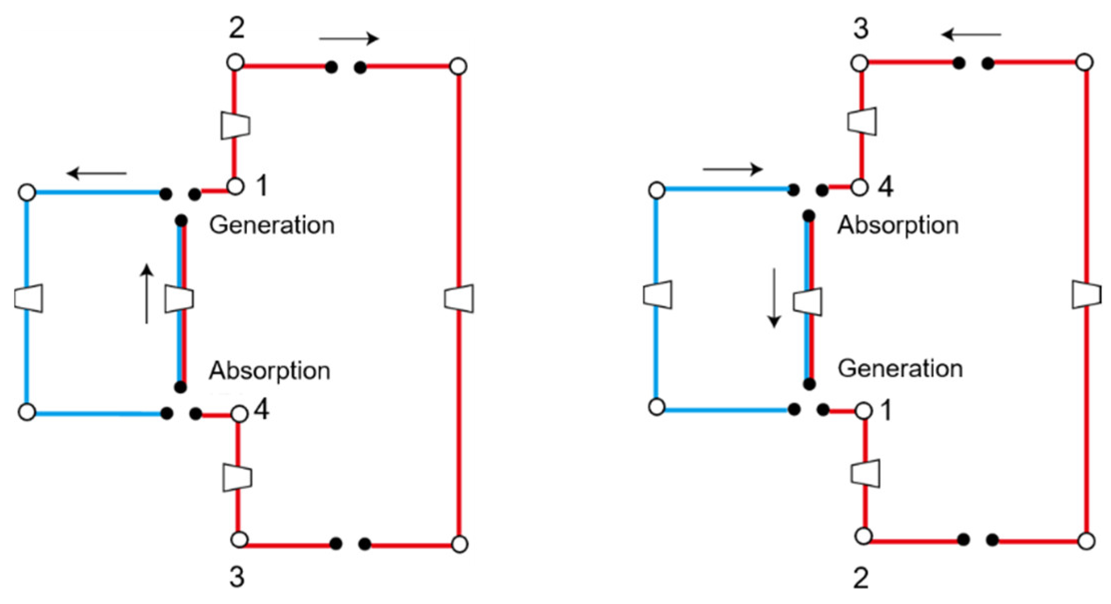
Figure 2 represents examples of the defined basic configuration for the absorption system consisting of two elementary cycles, in which each elementary cycle shares a part of compression(left)/expansion(right) process. It should be noted that the pressure of separated fluids at node 1/3 could sometimes be equal to the pressure at node 2/4, where the basic configuration does not have a non-shared compression(left)/expansion(right) process between node 1/3 and node 2/4.
There are various possible basic configurations classified according to not only the number of elementary cycles but also the number of absorption/generation processes. For example, a basic configuration made of two elementary cycles with one absorption/generation process and that with two absorption/generation processes are different in view of thermodynamics, where the input/output power in compression/expansion processes would be different from each other because of the difference of pressure range of shared compression/expansion processes operating with mixture. Therefore, it is proposed to search the configurations from those consisting of a few elementary thermodynamic cycles and a few absorption/generation processes.
2.2. Codification Method
The representation of a solution to the synthesis/design optimization problem is based on the decision variables, which should include information on the construction of cycle topologies and design parameters of the target system [9]. In addition, the assembling procedure must follow logical rules to make the candidate configurations feasible solutions. In fact, information on topology sometimes conflicts with information on design parameters. For instance, a case may occur where the pressure values at two nodes show the same value when calculated using topology codes and different value when calculated using design parameter codes. To avoid this situation, the general procedure involves instructions on which information designers should prioritize and which information they must ignore.
2.2.1. The Codification of Topology
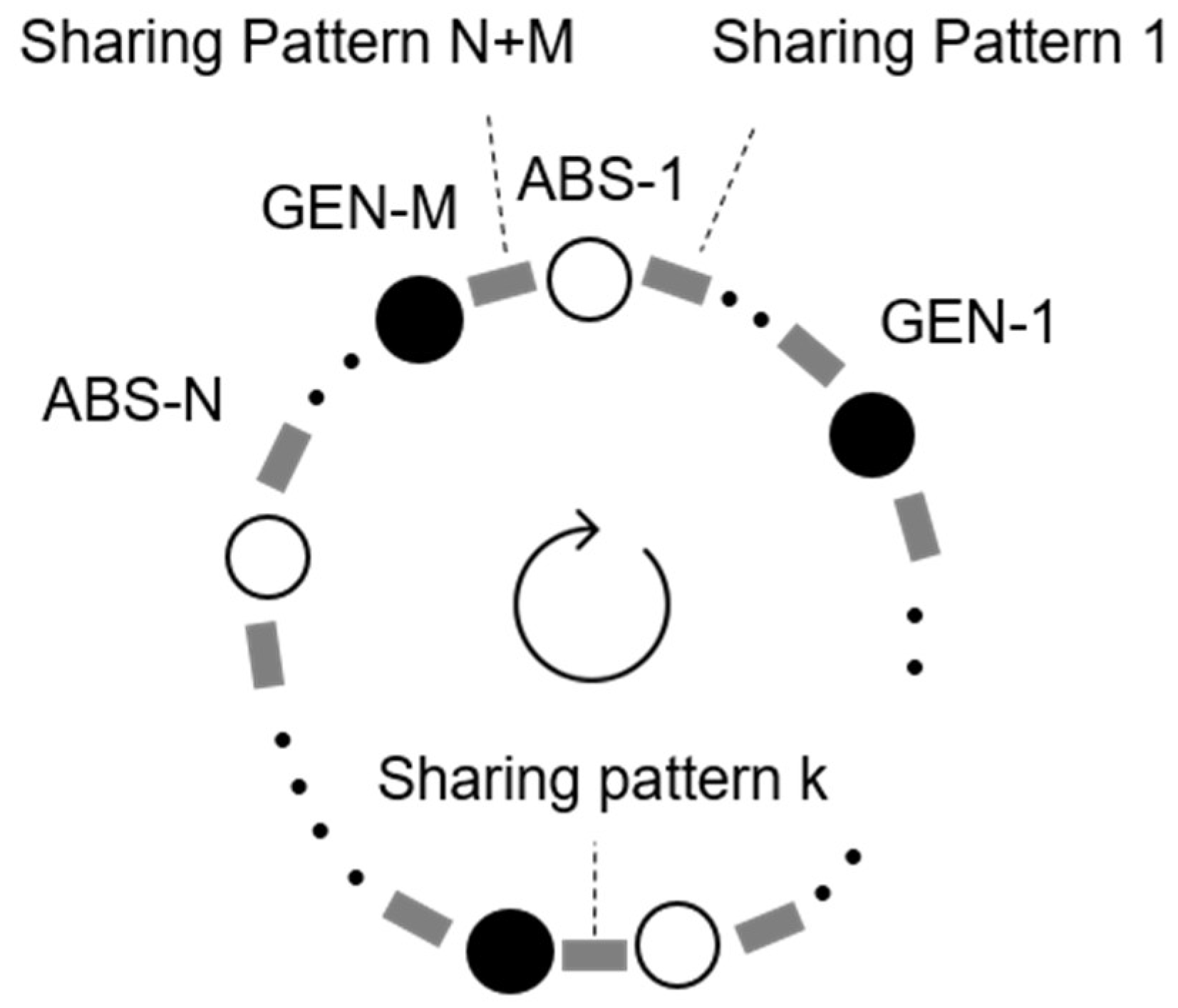
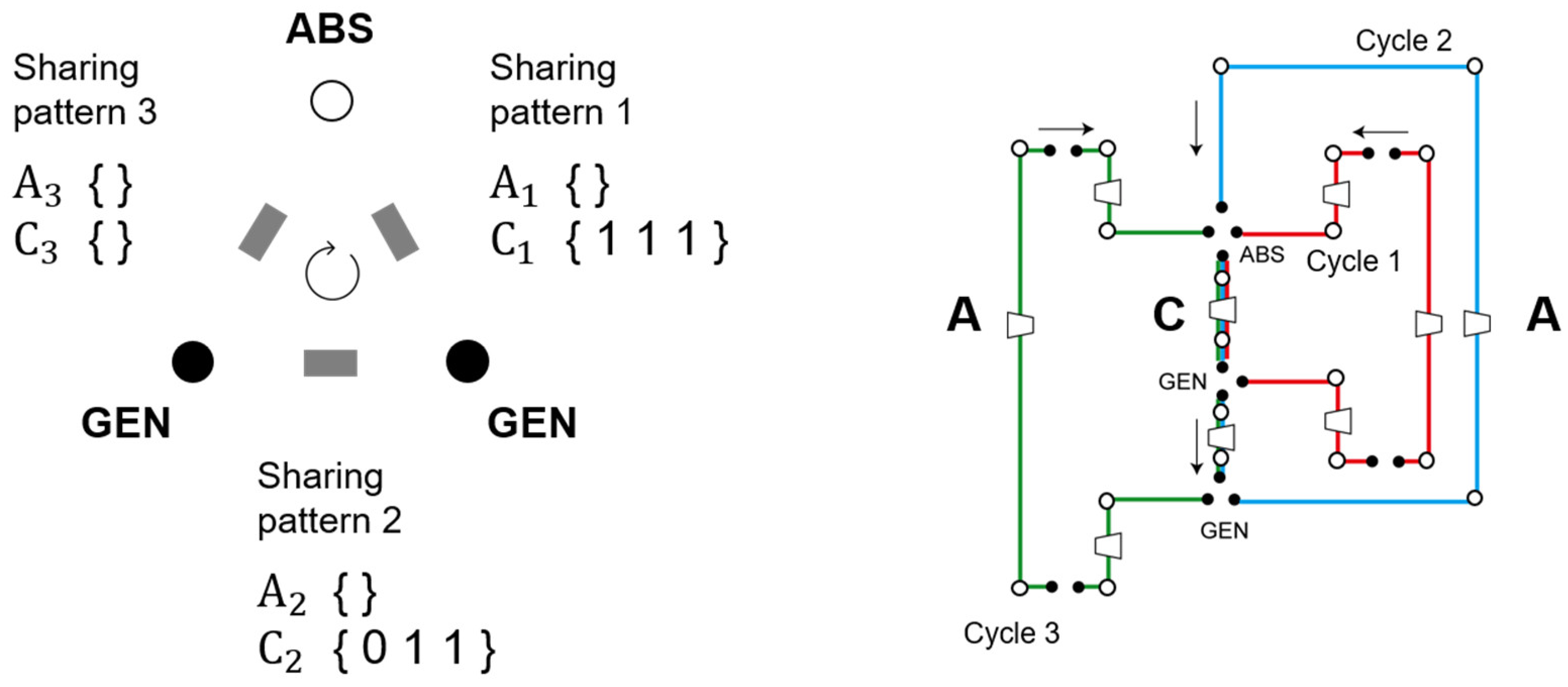
The goal of this section is to show the codification of the topology of the basic configurations for the absorption system. The code of the topology has to include the information about the shared elementary cycles and processes, the pattern of which is called “sharing pattern” in this paper. The sharing pattern must be defined in each phase between an absorption process and a generation process, because the main idea of this research proposes to search the configurations consisting of a fixed number of absorption/generation processes, which have the function to change the sharing pattern of each phase. Figure 3 shows an example of the order of the phases with each sharing pattern and the absorption/generation processes. Then, there is no constraint about the order of the absorption/generation processes and engineers should consider all possible orders. The number of the sharing patterns equals the sum of number of absorption processes and generation processes in a thermodynamically closed system.
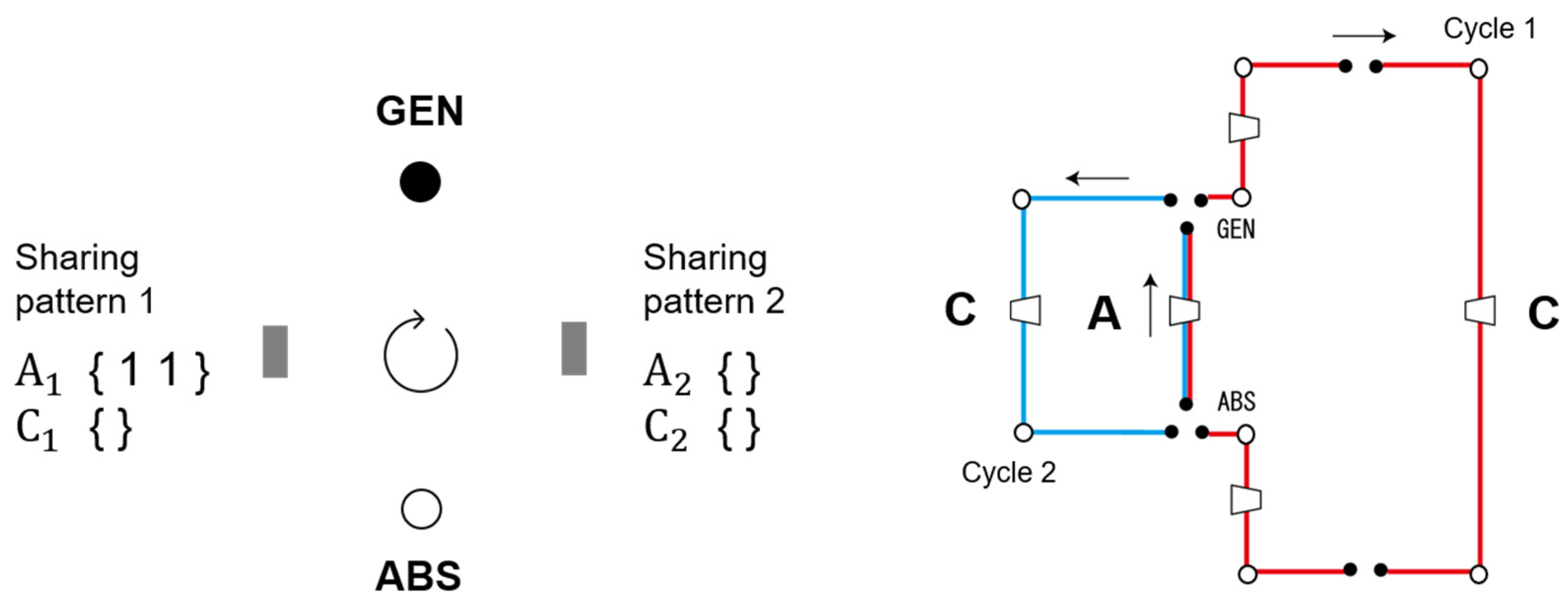
The codification features two types of lists of shared processes, one for each type of process (A: compression, C: expansion). Each list represents the elementary cycles shared and the working fluid mixed in each sharing pattern k, the numbering of which can be decided arbitrarily by the designer. List items are binary digits, and their number equals the number of aggregated elementary cycles. A list may be “1” at points that are linked in the shared process, represented by a vector. Moreover, a list may even be empty in case all the possible processes of that particular type occur separately in all elementary cycles. In other mathematical terms, this part of the codification for the sharing pattern k in the elementary Cycle i can be expressed as an organized collection of binary variables b:
Example 1: The following are four lists of shared processes in a basic configuration made of two elementary cycles and one absorption/generation process:
, , , indicate that (Figure 4):
- ; Cycle 1 and Cycle 2 share the compression process in sharing pattern 1.
- ; The expansion process of each elementary cycle in sharing pattern 1 is isolated.
- ; Cycle 1 and Cycle 2 does not share the compression process in sharing pattern 2.
- ; The expansion process of each elementary cycle in sharing pattern 2 is isolated.
As for the basic configuration made of one absorption/generation process, the order of these processes is determined as shown in Figure 4.
Example 2: The following are six lists of shared processes in a basic configuration made of three elementary cycles, one absorption process, and two generation processes:
indicate that (Figure 5):
- ; The compression process of each elementary cycle in sharing pattern 1 is isolated.
- ; Cycle 1, Cycle 2 and Cycle 3 share the expansion process in sharing pattern 1.
- ; The compression process of each elementary cycle in sharing pattern 2 is isolated.
- ; Cycle 2 and Cycle 3 share the expansion process in sharing pattern 2.
- ; The compression process of each elementary cycle in sharing pattern 3 is isolated.
- ; The expansion process of each elementary cycle in sharing pattern 3 is isolated.
As for the basic configuration made of one absorption process and two generation processes, the order of these processes is determined as shown in Figure 5.
2.2.2. The Codification of Design Parameters
The goal of this section is to show the codification of the intensive design parameters of the basic configurations for the absorption system. The design parameters in non-shared processes, indicating as “sep” in superscripts, are defined with seven real variables per working fluid of each elementary cycle (pressure at two nodes: the inlet and outlet of the compression process, specific enthalpy at the four nodes: the inlet and outlet of the compression process, the inlet and outlet of the expansion process, and mass fraction at any node), resulting in three matrixes or matrices such as:
with i: the number indicating each elementary cycle and j: the number indicating each node in elementary cycles; node 1: the inlet of the compression process, node 2: the outlet of the compression process, node 3: the inlet of the expansion process, node 4: the outlet of the expansion process. Note that the specific entropy of working fluids at node 2 could be calculated based on the information about the specific entropy at node 1, the pressure at nodes 1 and 2, and the equipment performance characteristics in the compression process, in the basic configuration with specific topology the elementary cycle does not share the compression process. In the same manner, the specific entropy of working fluids at node 4 could be calculated from the specific entropy at node 3 in the basic configuration with specific topology the elementary cycle does not share the expansion process. Moreover, in non-shared processes operating with absorbent solution, the design parameters about the specific entropy does not have to be defined, because that of the solution in its saturated liquid state could be calculated based on the information about the other intensive design parameters.
In shared processes, it is assumed that the mixture is in its saturated liquid state and the mass fraction of mixture could be calculated based on the information about the mass balance equations at absorption/generation processes, so the codification of the design parameters in shared processes includes one real variable, namely pressure at each absorption/generation process, resulting in two vectors:
where n represents the number indicating absorption processes, and m is the number indicating generation processes.
2.2.3. Interaction between Two Parts of the Codification: Topology and Design Parameters
The two parts of the codification are actually interdependent as shown in [9]. Considering the decision variables of the design parameters and topology independently leads to the generation of a large number of infeasible basic configurations. Moreover, information on topology sometimes conflicts with information on design parameters, and some information on one part of the codification has to be either corrected or ignored. The goal of this section is to construct a rule to consider the interaction between the two parts of the codification.
To assemble some elementary cycles into a basic configuration, the absorption and generation processes must be introduced at the inlet or the outlet of each shared process. In the absorption process, two different working fluids flow into the mixer and are mixed, after which the absorption heat is dissipated to external environment and the mixed working fluid enters its liquid phase. Then, there is no constraint on the operating properties of the separated working fluids right before the absorption process. On the other hand, during the generation process, the mixture working fluid is heated until some quantity of the working fluid becomes a vapor while the rest becomes liquid, after which the two working fluids are entirely separated. Therefore, the decision variables about design parameters indicating the operating properties of the separated working fluids right after generation must follow the constraint imposed by this real situation, where the operating properties of one fluid is in liquid phase while those of the other are in vapor phase.
In addition, the pressure exerted by the working fluids at the inlet of the absorption and generation processes and that of the working fluids at the outlet of these processes must be equal. Therefore, the pressure exerted by the mixture at the inlet of each shared compression process, in which some quantity of working fluids in the compression process of each elementary cycle is shared, is equal to the pressure exerted by the separated working fluid at the same point. In addition, this pressure must be larger than or equal to the pressure exerted by the separated working fluids at the inlet of the compression process. The pressure exerted by the mixture at the outlet of each shared compression process must be smaller or equal to than the pressure exerted by the separated working fluids at the outlet of the compression process. In the same manner, for the shared expansion process, the decision variables about design parameters must follow the constraint that the pressure values of the mixture are in the pressure range of the separated working fluids.
Information on topology may limit the pressure range of a working fluid in some elementary cycles as shown in Figure 6. In these basic configurations with specific topologies, the three working fluids of each elementary cycle are shared in the compression(left)/expansion(right) process right before a generation process and the two working fluids of elementary Cycles 2 and 3 are shared in the expansion(left)/compression(right) process right after the generation process; there are no separated compression/expansion processes after the generation process. Therefore, the decision variables about design parameters must meet the constraint that the pressure values of the two separated working fluids at the outlet of the compression(left)/expansion(right) process in the elementary Cycles 2 and 3 are equal to the pressure at the generation process. In other basic configurations with specific topologies, some working fluids of each elementary cycle are shared in the compression/expansion process right before an absorption process, and in the expansion/compression process right after the absorption process. For the basic configurations, in the same manner, the decision variables about the design parameters must follow a rigorous logical constraint about pressures of the working fluids.
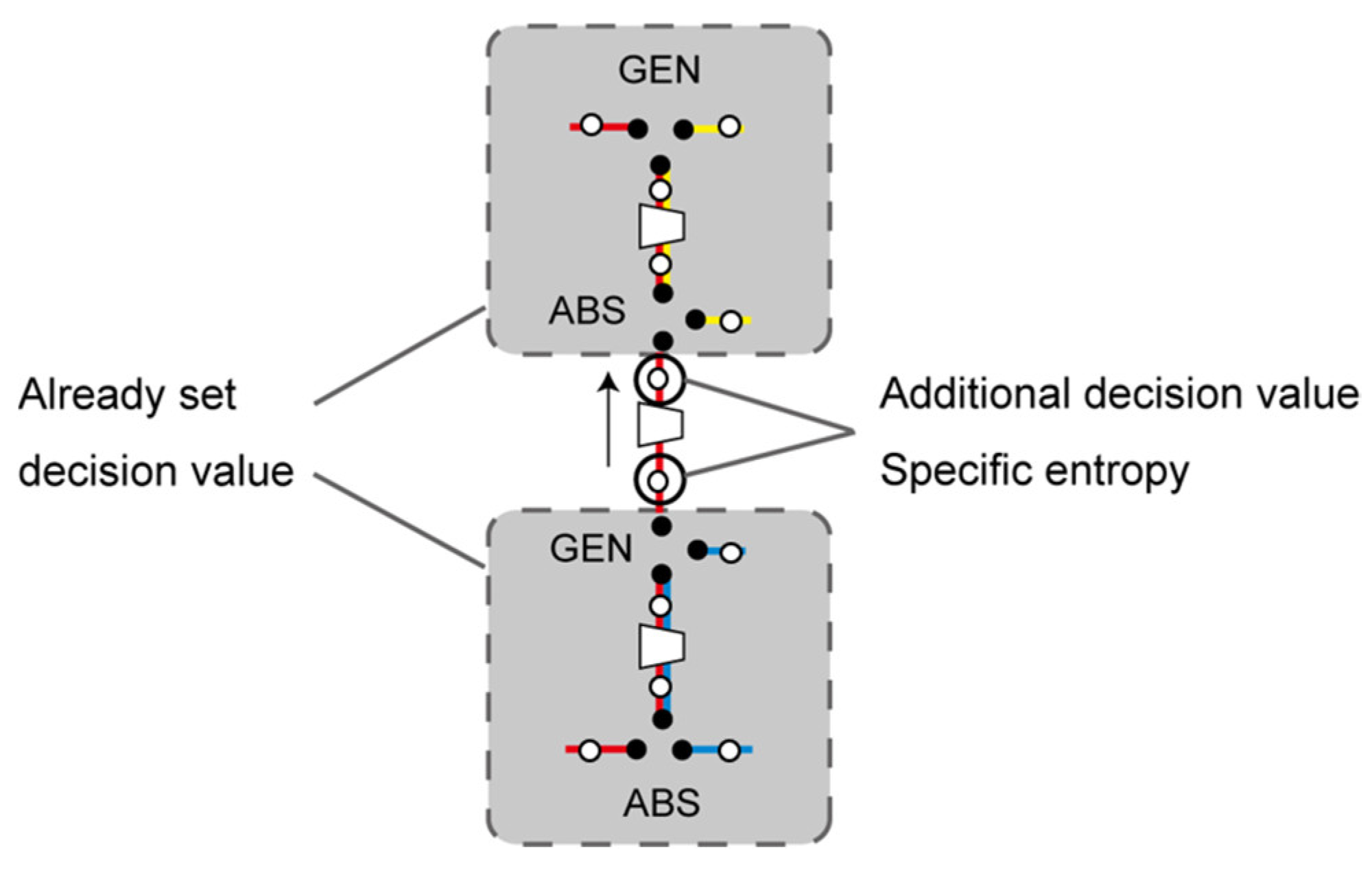
The design parameters of the working fluids in a non-shared process are defined by 7 real variables per working fluid of each elementary cycle. However, some basic configurations with specific topology would require additional decision variables for the specific entropy of certain separated working fluids, as can be seen Figure 7.
In these basic configurations, there are some non-shared processes between the shared compression/expansion processes. The specific entropy at the inlet/outlet of these non-shared processes should be considered in the optimization problem as additional decision variables because the properties cannot be determined based on information on other design parameters and topologies.
2.2.4. All Possible Topologies
The goal of this section is to clarify the number of all possible basic configurations for the absorption systems. The number is lower than that of all binary variable patterns in Equations (1) and (2), because some constraints must be considered to define the basic configurations:
- (1)
- Elementary cycles share either “compression” or “expansion” in each sharing pattern and could not share both. Therefore, all binaries for either shared process have to be zero in each sharing pattern.
- (2)
- In the shared process, two or more elementary cycles are shared. In the non-shared process, no elementary cycle is shared. Therefore, there cannot be a pattern in which the sum of all binaries for a shared process is one.
- (3)
- The number of elementary cycles shared after absorption is larger than that before the absorption. If an absorption process is located between the phase with sharing pattern and the phase with sharing pattern , then the following equation can be established:If an absorption process is located between the phase with sharing pattern and the phase with sharing pattern , then the following equation can be established:
- (4)
- The number of elementary cycles shared after the generation process is smaller than that shared before it. If a generation process is located between the phase with sharing pattern and the phase with sharing pattern , then the following equation can be established:If a generation process is located between the phase with sharing pattern and the phase with sharing pattern 1, then the following equation can be established:
Example 1: For basic configurations made of two elementary cycles, one absorption process, and one generation process, there could be two possible topologies for the absorption systems that meet the constraints.
Example 2: For basic configurations made of three elementary cycles, one absorption process, and two generation processes, there could be twelve possible topologies for the absorption systems that meet the constraints.
3. Demonstration for Synthesis/Design Optimization
This section presents examples of application to show the capability of the proposed bottom-up methodology to find optimal basic configurations for absorption technology-aid systems. Two case studies for optimization are performed to represent that the existing absorption refrigerator is rightfully chosen as the optimal solution from all possible absorption systems under the specific operating conditions. Besides, in earlier studies, it is predicted that the optimal effect number for an absorption refrigerator can be determined based on the heat source temperature under ideal operating conditions [31]. This section also attempts to evaluate and compare the calculated optimal solutions with those derived based on the previous optimal design methodology for the absorption refrigeration system [31].
3.1. Optimization Problem
3.1.1. Target System
This research focuses on an absorption system operating with water-lithium-bromide mixture, in which water is the refrigerant in saturated state, where the saturated liquid and saturated vapor coexist in vapor-liquid equilibrium state or either one exists, and water-lithium-bromide is the solution in saturated liquid state at all operating points.
This system aims to transfer heat from heat source to provide heat to supplied hot water and to remove heat from supplied chilled water. The simplified study assumes that the hot water temperature and the chilled water temperature are constant. The product of the system is either the heating capacity ( at the hot water temperature () or the refrigeration capacity () at the chilled water temperature (), while the system does not require net power output. It is set that the absorption heat in absorption processes is utilized as a part of heating capacity of a system ().
To obtain ideal conditions for the operating properties, the following assumptions are made:
- (1)
- There is no heat loss or pressure loss.
- (2)
- In heat exchange process, the difference between the temperatures of the hot and cold side at the pinch point is 0 °C.
- (3)
- In compression/expansion processes, the working fluid undergoes a reversible change and the properties undergo an isentropic change.
The demonstration targets the two types of basic configurations, a configuration made up of two elementary cycles and an absorption/generation process, and a configuration made up of three elementary cycles, an absorption process, and two generation processes, the topologies of which are as indicated in Equations (13) and (14).
3.1.2. Calculation Method
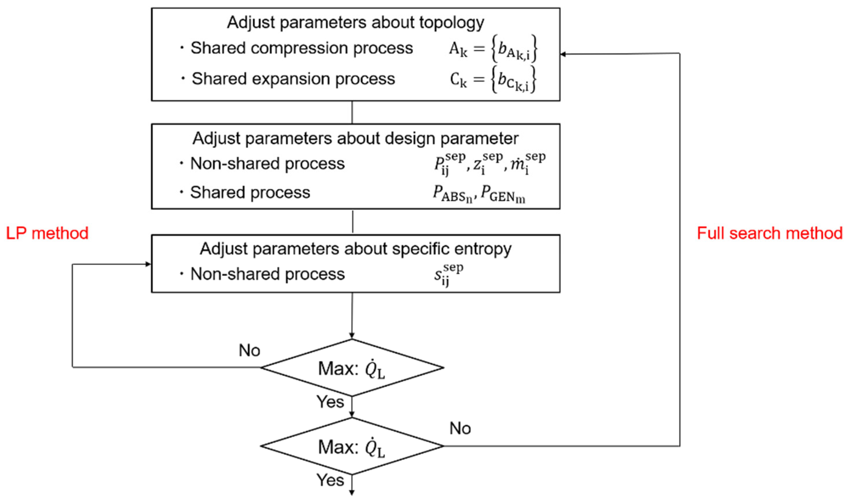
Figure 8 shows a flow chart of the synthesis/design optimization procedure. The optimization problem is solved using both the full search method and linear programming (LP) method, which is used to optimize the operating properties about specific entropy of refrigerants. To express the linear relationship between the parameters and the energy transfer rate from/to a refrigerant, we assume limited condition that a refrigerant is in its saturated state, where the saturated liquid and saturated vapor coexist or either one exists. Of course, if we apply a more general optimization methodology, we can explore a wider range of feasible solutions. The energy transfer rate from/to a refrigerant is calculated as the product of mass flow rate and the difference between specific enthalpy of refrigerant at the inlet and that at the outlet of each process. Then, the specific enthalpy of a refrigerant in saturated state at each node can be calculated based on the information about specific entropy at that node, with the linear relationship between specific entropy and specific enthalpy of the refrigerant in saturated state under the constant pressure (temperature) condition (Clausius—Clapeyron equation) [32]. Therefore, the relationship between the design parameters for specific entropy and the energy transfer rate from/to a refrigerant can be expressed as a linear one.
3.1.3. Decision Variables
The optimal topology and design parameters of the basic configuration are calculated by evaluating the following parameters:
<Topology variables>
- Lists of shared compression and expansion processes
<Design parameter variables>
- Operating properties of working fluid in non-shared process
- Pressure of mixture at absorption/generation processes
- Mass flow rate of working fluid in each elementary cycle
3.1.4. Constraints
The constraints include mass balance, energy balance, equipment performance characteristics, and operating conditions at several specific points. This study assumes that water is in the saturated state and water-lithium bromide is in the saturated liquid state in non-shared process, and the mixture of the two is in the saturated liquid state in shared process at all the nodes. In addition, it is assumed that the temperature of hot thermal stream is higher than or equal to the temperature of cold thermal stream in the same heat duty condition in the grand composite curves of the overall system. In the idealized condition, the minimum pinch temperature would be 0 °C. Hence, the constraint is established as follows:
- Hot thermal streamHeat duty is calculated as the heat transfer rate the working fluid and the heat source supplies to other fluids. This simplified demonstration does not consider the heating capacity of a system ( as a part of heat duty in the composite curves but adds a constraint that the temperature of refrigerant in heat exchange process with supplied hot water in each elementary cycle is higher than or equal to the hot water temperature ().
- Cold thermal streamHeat duty is calculated as the heat transfer rate the working fluid accepts from the heat source and other working fluids. This demonstration does not consider the refrigeration capacity ( as a part of heat duty in the composite curves but adds a constraint that the temperature of refrigerant in heat exchange process with supplied chilled water in each elementary cycle is lower than or equal to the chilled water temperature ().
The constraints also include information on an evaluation indicator as shown in Equation (24). This constraint compares the Carnot factor of a vapor compression refrigeration cycle between the same temperature ( and ) and the ratio between refrigeration capacity and input power in the absorption system, which is of high value in a system using heat as an energy source instead of an input power source such as the existing absorption systems. The constraints would enable us to get the existing absorption system as a solution from any energy systems by setting the value , which is chosen by the designers based on information about environmental conditions and use applications.
3.1.5. Objective Function
The objective function is set as the output refrigeration capacity obtained under the fixed heat source conditions. In addition, the is defined as the evaluation indicator of system performance. The is expressed as the ratio of output refrigeration capacity to the input energy rate of the system, which equals the net heat rate transferred from the external environment in generation processes and can be calculated as in Equation (25), where is the heat rate recovered from an internal working fluid flowing in other processes.
3.2. Demonstration
This section aims to perform optimization for an absorption system under specific operating conditions and represent the capability of the proposed methodology to find basic configurations that can generate the maximum refrigeration capacity. The calculated solutions are evaluated and compared with those derived from the previous optimal design methodology [31].
3.2.1. Input Parameters
Input parameters are shown in Table 1, including the heat source condition and operating conditions at a few points. The two cases have a difference in the operating condition—heat source temperature.
3.2.2. Results and Discussion
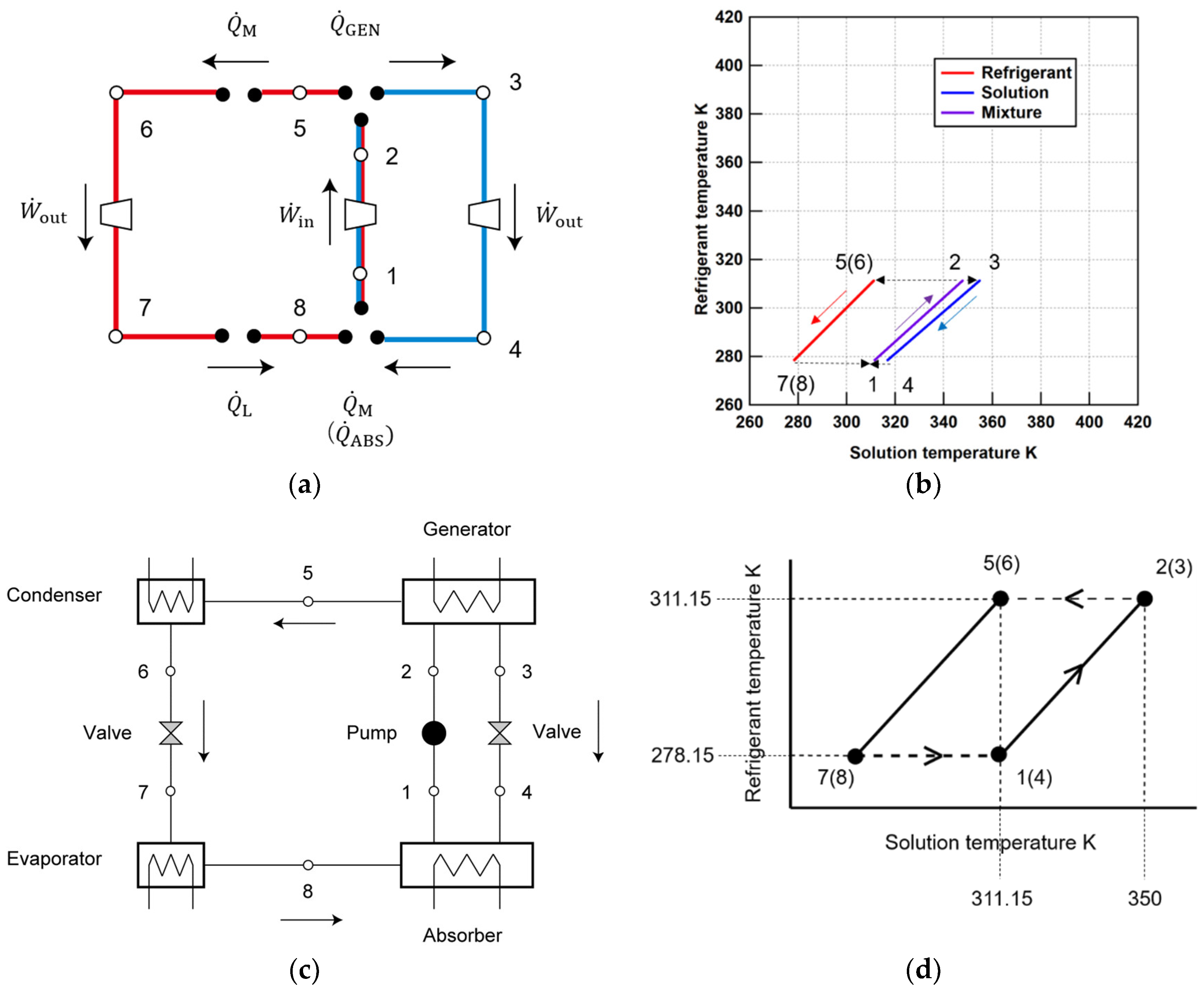
This section describes the calculated optimal solution based on the defined optimization problem and evaluate the solutions by comparing the calculated solutions with those derived based on the previous optimal design methodology for the absorption refrigerator. In case X, it is known from a literature [31] that the optimal absorption refrigeration system with the highest is the single-effect one under a constant heat source temperature of 90 °C. The calculated solution in this study seems to be reasonable because the optimal configuration and operating properties in the Dühring chart is very similar to those in an existing single-effect absorption refrigeration system, as shown in Figure 9. In both cycle configurations, the mixture (node 2) is separated into the absorbent solution fluid (node 3) and the refrigerant fluid (node 5) in the generation process. The separated absorbent solution is expanded and flows to the absorption process (node 4), while the refrigerant is used as a working fluid to produce the heating/refrigeration capacity of the system before passing it to the absorption process (nodes 5, 6, 7, 8). The basic configuration has a shared compression process between two elementary cycles (nodes 1, 2), but no non-shared compression process. Therefore, only the mixed solution flows in the compression process to reduce the required input power as in Table 2. Moreover, the operating points in the calculated solution is also similar to that in the solutions in the previous study, as shown Figure 9. As in Figure 9d, the difference of mass fraction of absorbent solution and mixture cannot appear in the Dühring chart of the solution in the previous study because it is assumed that the mass flow rate of absorbent solution is much larger than that of refrigerant, resulting in a little difference of operating points of two systems. Because of the too idealized assumptions in the previous problem, the two solutions have a little difference, however, it could be said that the calculated solution in this demonstration could express the main features of the solution in the previous study. As a result, the in calculated solution is 0.82, which is near to the of the solution in the previous study: 0.9.
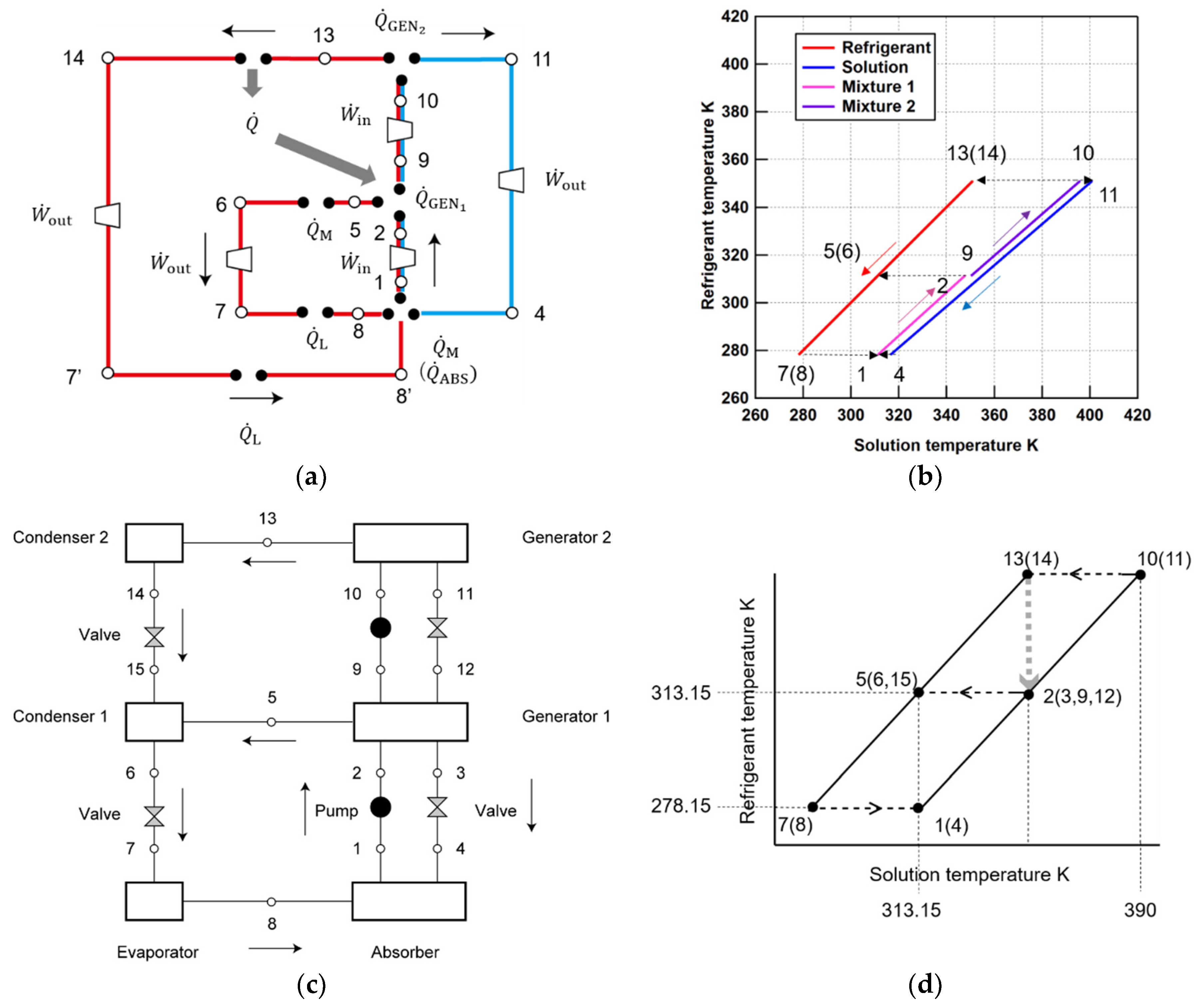
In case Y, it is known from [31] that the optimal absorption refrigeration system with the highest is the double-effect one under a constant heat source temperature of 130 °C. The calculated solution in this study seems to be reasonable because the optimal configuration and operating properties in the Dühring chart is very similar to those in an existing double-effect absorption refrigeration system, as shown in Figure 10.
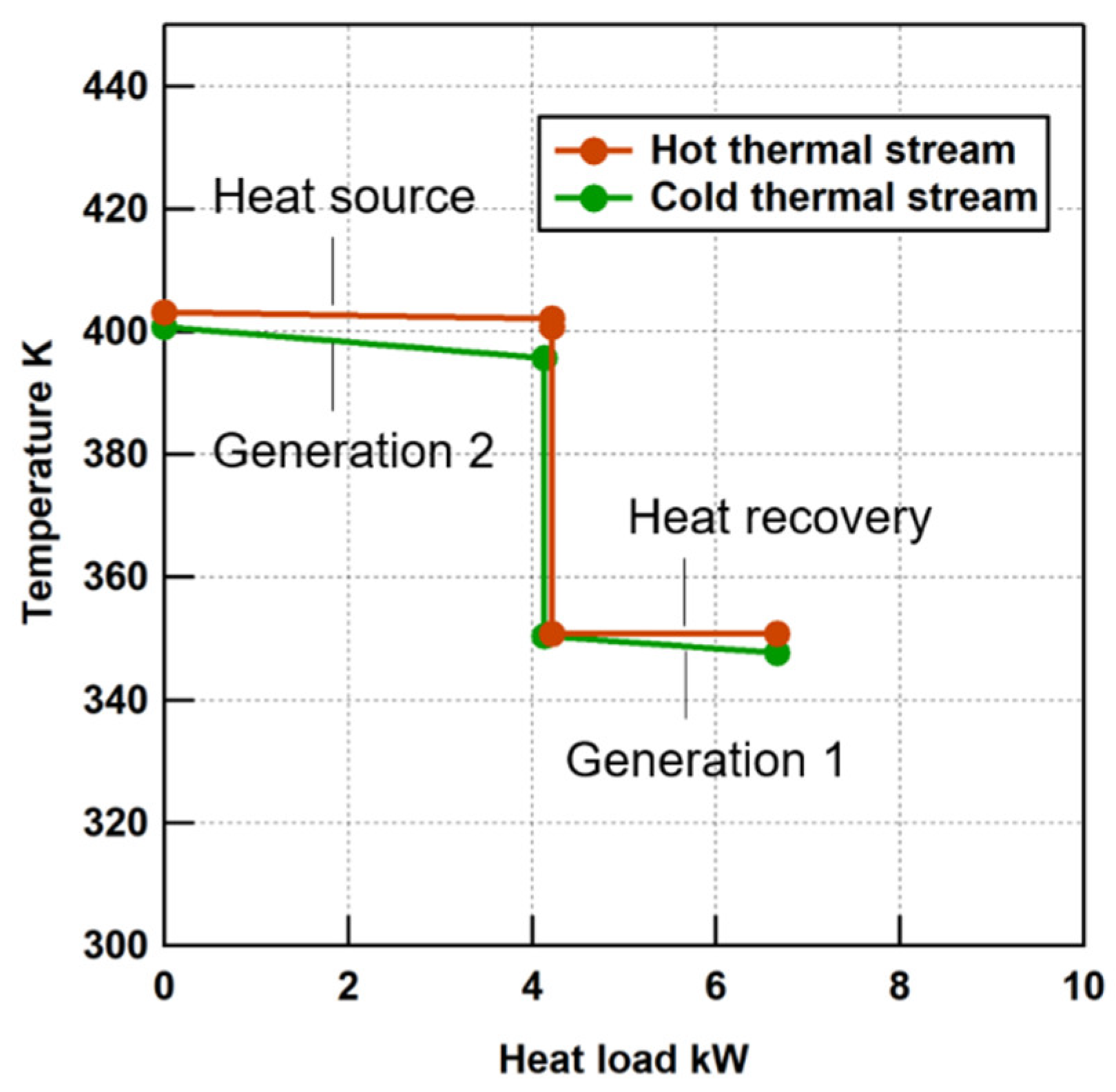
In both cycle configurations, the dilute mixed solution (node 1) is compressed (node 2) and separated into the concentrated solution fluid (node 9) and the refrigerant fluid (node 5) in generation process 1. The separated refrigerant fluid is used as the working fluid to produce heating/refrigeration capacity of the system before being transported to the absorption process (nodes 5, 6, 7, 8). The separated solution fluid is compressed (node 10) and separated into the absorbent solution (node 11) and the refrigerant (node 13). The separated solution is expanded and transported to the absorption process (node 4), while the refrigerant is cooled (node 13, 14); the heat is reused as a part of generation heat in generation process 1. After this, the refrigerant is expanded (node 7’) and used as the working fluid to produce refrigeration capacity of the system (nodes 7’, 8’). The refrigeration capacity of the system is produced through two mass flows in the calculated solution; however, the refrigeration capacity calculated is the same as that in the configuration in which the two mass flows are shared, because the mass fraction, pressure, and temperature of the two working fluids are the same at the cooling processes and the absorption process. On the other hand, the calculated solution of the optimal basic configuration does not consider heat exchange between the absorbent solution (nodes 4, 11) and the other working fluids in the generation process 1 because of the assumption that the solution fluid is in the saturated liquid state at all operating points in the defined optimization problem. However, the calculated solution could still express the main benefits of an existing absorption system. First, the optimal basic configuration has a shared compression processes between two or three elementary cycles and only the mixture solution flows into the compression process to reduce the required input power as in Table 3. Second, the heat dissipated from the refrigerant right after the generation process at higher pressure (between nodes 13 and 14) is recovered and utilized as the generation heat at a lower pressure in the system as shown in Figure 11. Moreover, the operating points in the calculated solution are also similar to that of the solution in the previous study as shown in Figure 10b,d. It could be said that the calculated solution in this demonstration could express the main features of the solution in the previous study. As a result, the in calculated solution is 1.54, which is near to the of the solution in the previous study: 1.7.
4. Conclusions
Our study aims to propose a general bottom-up methodology to develop basic configurations for energy system with absorption technology by extending the pioneering SYNTHSEP methodology. The methodology proposes to define a basic configuration for the absorption system as a set of elementary Rankine/Refrigeration cycles and absorption/generation processes and develops the codification method so that an optimization algorithm can implement the organized rules to generate new candidate basic configurations for the absorption system in the optimization problem. Two examples of application are presented to show the capability of the proposed methodology to find basic configurations that can generate the maximum product. The demonstration shows that the existing absorption systems, which would be calculated based on the experience of energy conversion system designers, could be derived by performing the synthesis/design optimization automatically using the proposed synthesis methodology under the simplified/idealized operating conditions. The proposed bottom-up methodology is significant for realizing the synthesis/design optimization for the absorption system, because it can allow engineers to predict all possible configurations in advance and identify a simple and feasible optimal system configuration. The development of the bottom-up synthesis methodology for more types of energy systems may allow us to approach the ultimate goal: the construction of the methodology to derive an optimized system that utilizes available resources to generate the maximum product with minimum components, which can be applied to all types of energy system.
Future work should consider heating/cooling processes operating with absorbent solution or mixed solution in its saturated state or compressed liquid state. It would enable engineers to explore the search space of optimization problem more deeply. Furthermore, certain working fluids would be superheated at certain points in the exiting absorption power and cooling systems, in which the net power is considered as a system product. This methodology should be explored to optimize systems considering superheating and sub-cooling of the working fluids in order to perform the optimization for absorption power and cooling system.
Author Contributions
Original draft preparation K.S.; supervision Y.A.; conceptualization, K.S. and Y.A. and K.T.; methodology, K.S.; writing—review and editing, K.S. and Y.A.; visualization, K.S.; numerical simulations, K.S.
Funding
A part of this work is supported by CREST, the Japan Science and Technology Agency, Grant Number JPMJCR15K5.
Acknowledgments
We would like to express my sincere gratitude to Andrea Lazzaretto and Andrea Toffolo for their valuable comments. Moreover, a part of this work is supported by CREST, headed by Yasuhiro Hayashi, the Japan Science and Technology Agency, Grant Number JPMJCR15K5.
Conflicts of Interest
The authors declare no conflict of interest.
Nomenclature
| List expressing compression process | |
| Binary variable | |
| List expressing heating process | |
| List expressing expansion process | |
| Specific heat at constant pressure kJ/(kg·°C) | |
| Coefficient of performance | |
| List expressing cooling process | |
| Coefficient utilized in the optimization problem | |
| Specific enthalpy kJ/kg | |
| I | The number of elementary cycles in a system |
| Mass flow rate kg/s | |
| The number of generation processes in a system | |
| The number of absorption processes in a system | |
| Pressure MPa | |
| Heat exchange rate kW | |
| Specific entropy kJ/(kg·°C) | |
| Temperature °C or K | |
| Power rate kW | |
| Mass fraction kg/kg | |
| Subscripts | |
| abs | Absorption system |
| ABS | Absorption process |
| amb | Ambient condition |
| c | Cold thermal stream |
| GEN | Generation process |
| h | Hot thermal stream |
| H | Heat source |
| i | Number indicating each elementary cycle |
| in | Inlet |
| j | Number indicating operating node |
| k | Number indicating each sharing pattern |
| L | Refrigerant capacity |
| M | Heating capacity |
| m | Number indicating each generation process |
| n | Number indicating each absorption process |
| out | Outlet |
| rec | Heat recovery |
| sep | Working fluid in non-shared process |
References
- Frangopoulos, C.A.; Spakovsky, M.; Sciubba, E. A brief review of methods for design and synthesis optimization of energy systems. Int. J. Appl. Thermodyn. 2002, 5, 151–160. [Google Scholar]
- Bertran, M.O.; Frauzem, R.; Sanchez-Arcilla, A.S.; Zhang, L.; Woodley, J.M.; Gani, R. A generic methodology for processing route synthesis and design based on superstructure optimization. Comput. Chem. Eng. 2017, 106, 892–910. [Google Scholar] [CrossRef]
- Cui, C.; Li, X.; Sui, H.; Sun, J. Optimization of coal-based methanol distillation scheme using process superstructure method to maximize energy efficiency. Energy 2017, 119, 110–120. [Google Scholar] [CrossRef]
- Kwon, S.; Won, W.; Kim, J. A superstructure model of an isolated power supply system using renewable energy: Development and application to Jeju Island, Korea. Renew. Energy 2016, 97, 177–188. [Google Scholar] [CrossRef]
- Emmerich, M.; Grötzner, M.; Schütz, M. Design of graph-based evolutionary algorithms: A case study for chemical process networks. Evol. Comput. 2001, 9, 329–354. [Google Scholar] [CrossRef] [PubMed]
- Angelov, P.; Zhang, Y.; Wright, J.; Hanby, V.; Buswell, R. Automatic design synthesis and optimization of component-based systems by evolutionary algorithms. In In Proceedings of the Genetic and Evolutionary Computation Conference, Chicago, IL, USA, 12–16 July 2003; Cantú-Paz, E., Foster, J.A., Deb, K., Davis, L.D., Roy, R., O’Reilly, U.-M., Beyer, H.-G., Standish, R., Kendall, G., Wilson, S., et al., Eds.; Springer: Berlin/Heidelberg, Germany, 2003; p. 213. [Google Scholar]
- Urselmann, M.; Emmerich, M.T.; Till, J.; Sand, G.; Engell, S. Design of problem-specific evolutionary algorithm/mixed-integer programming hybrids: Two-stage stochastic integer programming applied to chemical batch scheduling. Eng. Optimiz. 2007, 39, 529–549. [Google Scholar] [CrossRef]
- Wright, J.; Zhang, Y.; Angelov, P.; Hanby, V.; Buswell, R. Evolutionary synthesis of HVAC system configurations: Algorithm development (RP-1049). HVAC&R Res. 2008, 14, 33–55. [Google Scholar]
- Toffolo, A. A synthesis/design optimization algorithm for Rankine cycle based energy systems. Energy 2014, 66, 115–127. [Google Scholar] [CrossRef]
- Toffolo, A.; Rech, S.; Lazzaretto, A. Combination of Elementary Progresses to Form a General Energy System Configuration. In Proceedings of the ASME 2017 International Mechanical Engineering Congress & Exposition IMECE2017, Tampa, FL, USA, 3–9 November 2017. [Google Scholar]
- Toffolo, A.; Rech, S.; Lazzaretto, A. Generation of Complex Energy Systems by Combination of Elementary Processes. J. Energy Resour. Technol. 2018, 140, 1–11. [Google Scholar] [CrossRef]
- Lazzaretto, A.; Toffolo, A. A practical tool to generate complex energy system configurations based on the SYNTHSEP methodology. In Proceedings of the ECOS 2018, 31st International Conference of Efficiency, Cost, Optimization, Simulation and Environmental Impact of Energy Systems, Guimarães, Portugal, 17–22 June 2008. [Google Scholar]
- Lazzaretto, A.; Segato, F. Thermodynamic optimization of the HAT cycle plant structure—Part I: Optimization of the “basic plant configuration”. J. Eng. Gas Turb. Power 2000, 123, 1–7. [Google Scholar] [CrossRef]
- Lazzaretto, A.; Segato, F. Thermodynamic optimization of the HAT cycle plant structure—Part II: Structure of the heat exchanger network. J. Eng. Gas Turb. Power 2000, 123, 8–16. [Google Scholar] [CrossRef]
- Lazzaretto, A.; Toffolo, A. A method to separate the problem of heat transfer interactions in the synthesis of thermal systems. Energy 2008, 33, 163–170. [Google Scholar] [CrossRef]
- Morandin, M.; Toffolo, A.; Lazzaretto, A. Superimposition of elementary thermodynamic cycles and separation of the heat transfer section in energy systems analysis. J. Energy Resour. Technol. 2013, 135, 021602. [Google Scholar] [CrossRef]
- Goswami, D.Y. Solar thermal power technology: Present status and ideas for the future. Energy Sources 1998, 20, 137–145. [Google Scholar] [CrossRef]
- Xu, F.; Goswami, D.Y.; Bhagwat, S.S. A combined power/cooling cycle. Energy 2000, 25, 233–246. [Google Scholar] [CrossRef]
- Martin, C.; Goswami, D.Y. Effectiveness of cooling production with a combined power and cooling thermodynamic cycle. Appl. Therm. Eng. 2006, 26, 576–582. [Google Scholar] [CrossRef]
- Fontalvo, A.; Pinzon, H.; Duarte, J.; Bula, A.; Quiroga, A.G.; Padilla, R.V. Exergy analysis of a combined power and cooling cycle. Appl. Therm. Eng. 2013, 60, 164–171. [Google Scholar] [CrossRef]
- Herold, K.E.; Radermacher, R.; Klein, S.A. Absorption Chillers and Heat Pumps, 2nd ed.; CRC Press: Boca Raton, FL, USA, 1996; pp. 7–22 & 235–254. [Google Scholar]
- Swartman, R.K.; Ha, V.; Swaminathan, C. Comparison of ammonia-water and ammonia-sodium thiocyanate as the refrigerant-absorbent in a solar refrigeration system. Sol. Energy 1975, 17, 123–127. [Google Scholar] [CrossRef]
- Best, R.; Heard, C.L.; Fernández, H.; Siqueiros, J. Developments in geothermal energy in Mexico-Part five: The commissioning of an ammonia/water absorption cooler operating on low enthalpy geothermal energy. Heat Recovery Syst. 1986, 6, 209–216. [Google Scholar] [CrossRef]
- Siddiqui, M.A. Optimum generator temperatures in four absorption cycles using different sources of energy. Energy Convers. Manag. 1993, 34, 251–266. [Google Scholar] [CrossRef]
- Fernández-Seara, J.; Vales, A.; Vázquez, M. Heat recovery system to power an onboard NH3-H2O absorption refrigeration plant in trawler chiller fishing vessels. Appl. Therm. Eng. 1998, 18, 1189–1205. [Google Scholar] [CrossRef]
- Bejan, A. Advanced Engineering Thermodynamics, 4th ed.; John Wiley & Sons Inc.: Hoboken, NJ, USA, 2016; pp. 531–599. [Google Scholar]
- Myat, A.; Thu, K.; Kim, Y.; Chakraborty, A.; Chun, W.G.; Ng, K.C. A second law analysis and entropy generation minimization of an absorption chiller. Appl. Therm. Eng. 2011, 31, 2405–2413. [Google Scholar] [CrossRef]
- Wu, W.; Wang, B.; Shi, W.; Li, X. An overview of ammonia-based absorption chillers and heat pumps. Renew. Sustain. Energy Rev. 2014, 31, 681–707. [Google Scholar] [CrossRef]
- Ziegler, F.; Alefeld, G. Coefficient of performance of multistage absorption cycles. Int. J. Refrig. 1987, 10, 285–295. [Google Scholar] [CrossRef]
- Alefeld, G.; Radermacher, R. Heat Conversion System.; CRC Press: Boca Raton, FL, USA, 1994; pp. 179–206. [Google Scholar]
- Inoue, N. Studies on the Characteristics of Absorption Cycles and their Applications. Ph.D. Thesis, Waseda University, Tokyo, Japan, 3 March 2005. [Google Scholar]
- Kolaczkiewics, J.; Bauer, E. Clausius-Clapeyron equation analysis of two- dimensional vaporization. Surf. Sci. 1985, 155, 700–714. [Google Scholar] [CrossRef]
Figure 1.
Basic configuration of elementary thermodynamic cycle.

Figure 2.
Examples of the basic configuration for the absorption system that is obtained by assembling two elementary cycles, in which each elementary cycle shares a part of compression(left)/expansion(right) process. (red line—refrigerant, blue line—absorbent solution).
Figure 2.
Examples of the basic configuration for the absorption system that is obtained by assembling two elementary cycles, in which each elementary cycle shares a part of compression(left)/expansion(right) process. (red line—refrigerant, blue line—absorbent solution).

Figure 3.
Order of the phases with each sharing pattern and the absorption/generation processes.

Figure 4.
An example of topology definition of a basic configuration, including two elementary cycles and one absorption/generation process. (red line—refrigerant, blue line—absorbent solution).
Figure 4.
An example of topology definition of a basic configuration, including two elementary cycles and one absorption/generation process. (red line—refrigerant, blue line—absorbent solution).

Figure 5.
An example of topology definition of a basic configuration for the absorption system including three elementary cycles and one absorption process and two generation processes. (red line, green line—refrigerant, blue line—absorbent solution).
Figure 5.
An example of topology definition of a basic configuration for the absorption system including three elementary cycles and one absorption process and two generation processes. (red line, green line—refrigerant, blue line—absorbent solution).

Figure 6.
Examples of topologies that limit pressure range of working fluids in non-shared processes. (red line, green line—refrigerant, blue line—absorbent solution). (left); (right).
Figure 6.
Examples of topologies that limit pressure range of working fluids in non-shared processes. (red line, green line—refrigerant, blue line—absorbent solution). (left); (right).

Figure 7.
An example of topologies that require definition of several additional design parameters. (red line—refrigerant, blue line, yellow line—absorbent solution).
Figure 7.
An example of topologies that require definition of several additional design parameters. (red line—refrigerant, blue line, yellow line—absorbent solution).

Figure 8.
Optimization calculation procedure.

Figure 9.
Optimal solution in case X (red line—refrigerant, blue line—absorbent solution): (a) Basic configuration calculated; (b) Operating properties calculated; (c) Cycle configuration of an existing single-effect absorption refrigerator; (d) Operating properties of an existing system.
Figure 9.
Optimal solution in case X (red line—refrigerant, blue line—absorbent solution): (a) Basic configuration calculated; (b) Operating properties calculated; (c) Cycle configuration of an existing single-effect absorption refrigerator; (d) Operating properties of an existing system.

Figure 10.
Optimal solution in case Y (red line—refrigerant, blue line—absorbent solution): (a) Basic configuration calculated; (b) Operating properties calculated; (c) Cycle configuration of an existing double-effect absorption refrigerator; (d) Operating properties of an existing system.
Figure 10.
Optimal solution in case Y (red line—refrigerant, blue line—absorbent solution): (a) Basic configuration calculated; (b) Operating properties calculated; (c) Cycle configuration of an existing double-effect absorption refrigerator; (d) Operating properties of an existing system.

Figure 11.
Composite curves of the optimal solutions in case Y.


Table 1.
Input parameters of the operating properties of working fluids in the case studies.
| Item | Symbol | Unit | Value | |
|---|---|---|---|---|
| Case X | Case Y | |||
| Mass flow rate of heat source fluid | kg/s | 1.0 | ||
| Specific heat at constant pressure of heat source | kJ/(kg·°C) | 4.217 | ||
| Heat source temperature at system inlet | °C | 90 | 130 | |
| Heat source temperature at system outlet | °C | |||
| Hot water temperature | °C | 38 | ||
| Chilled water temperature | °C | 5 | ||
| Mass fraction of working fluid in Cycle 1 | kg/kg | 0 | ||
| Mass fraction of working fluid in Cycle 3 | kg/kg | 0 | ||
| Coefficient included in the constraint (24) | - | 100 | ||
Table 2.
Calculated values about the energy exchange rate in case X.
| Item | Symbol | Unit | Value |
|---|---|---|---|
| Output power | W | 12.25 | |
| Input power | W | 0.76 | |
| Output heating capacity | W | 7637 | |
| Generation heat rate | W | 4201 | |
| Heat recovery rate | W | 0 | |
| Heat source potential energy | W | 4217 | |
| Coefficient of performance | - | 0.82 | |
| Output refrigeration capacity | W | 3448 |
Table 3.
Calculated values about the energy exchange rate in case Y.
| Item | Symbol | Unit | Value |
|---|---|---|---|
| Output power | W | 59.51 | |
| Input power | W | 3.27 | |
| Output heating capacity | W | 8989 | |
| Generation heat rate | W | 6666 | |
| Heat recovery rate | W | 3471 | |
| Heat source potential energy | W | 4217 | |
| Coefficient of performance | - | 1.54 | |
| Output refrigeration capacity | W | 4908 |
© 2019 by the authors. Licensee MDPI, Basel, Switzerland. This article is an open access article distributed under the terms and conditions of the Creative Commons Attribution (CC BY) license (http://creativecommons.org/licenses/by/4.0/).
Share and Cite
MDPI and ACS Style
Seki, K.; Takeshita, K.; Amano, Y. Development of Complex Energy Systems with Absorption Technology by Combining Elementary Processes. Energies 2019, 12, 495. https://doi.org/10.3390/en12030495
AMA Style
Seki K, Takeshita K, Amano Y. Development of Complex Energy Systems with Absorption Technology by Combining Elementary Processes. Energies. 2019; 12(3):495. https://doi.org/10.3390/en12030495
Chicago/Turabian StyleSeki, Kosuke, Keisuke Takeshita, and Yoshiharu Amano. 2019. "Development of Complex Energy Systems with Absorption Technology by Combining Elementary Processes" Energies 12, no. 3: 495. https://doi.org/10.3390/en12030495
Note that from the first issue of 2016, this journal uses article numbers instead of page numbers. See further details here.