Analysis of Thermal Performance and Energy Saving Potential by PCM Radiant Floor Heating System based on Wet Construction Method and Hot Water


1
Industry Academic Cooperation Foundation, Hankyong National University, 327, Jungang-ro, Anseong-si, Gyeonggi-do 17579, Korea
2
School of Architecture, Hankyong National University, 327, Jungang-ro, Anseong-si, Gyeonggi-do 17579, Korea
*
Author to whom correspondence should be addressed.
Energies 2019, 12(5), 828; https://doi.org/10.3390/en12050828
Submission received: 19 January 2019
/
Revised: 22 February 2019
/
Accepted: 22 February 2019
/
Published: 2 March 2019
(This article belongs to the Section D: Energy Storage and Application)
Abstract
:A phase change material (PCM) is an energy storage mass with high heat storage performance. In buildings, PCMs can be utilized to save energy in radiant floor heating systems. This study aims to analyze the thermal performance and energy saving potential by the PCM radiant floor heating system based on wet construction method and hot water. For such analysis, EnergyPlus program was used. As for the results, it was found that the proposed system almost maintained the set point of indoor air and a floor surface. Moreover, when a 10 mm PCM was applied, it was possible to save 2.4% of heating energy annually compared to existing buildings. In particular, when a 20–50 mm PCM was applied, it was found that 7.3–15.3% of heating energy was reduced annually. If indoor air temperature exceeds the comfort range of the proposed system, this problem can be solved by adjusting the set point of the floor surface or by increasing the temperature of hot water.
1. Introduction
Studies on thermal energy storage systems that combine phase change materials (PCMs) with building structures have been actively conducted to reduce the heating energy consumption in buildings [1]. In particular, studies have been continuously conducted on PCM radiant floor heating systems, which can decrease heating energy by improving the energy performance of existing radiant floor heating systems [2,3,4,5,6,7,8,9,10,11].
Lin, K. et al. developed a shape-stabilized PCM (SSPCM) plate to be applied to a radiant floor heating system and proved that this system could maintain the indoor heating temperature in the comfort range through theories and computer simulation [2]. Moreover, they introduced a new radiant floor heating system that could perform heating by combining an office floor with an air cavity including an SSPCM plate and supplying air into the office through a floor diffuser. It was found through experiments that this system could effectively reduce the electrical energy consumed for office heating during daylight hours and maintain indoor temperature in the comfort range [3]. Jin, X. et al. introduced a PCM floor heating system that could perform cooling and heating by inserting cooling and heating coils and low-temperature and high-temperature PCMs into a floor structure. Through simulation, they found that the annual energy consumption could be reduced by approximately 37.9–41.1% using the proposed system [4]. Huang, K. et al. introduced a PCM radiant floor heating system with a solar hot-water system. This system had a unique structure in which a PCM and a capillary hot-water coil were combined on a floor in a grid form without the use of a PCM case. This system not only maintained the indoor set point in a stable manner but also decreased energy consumption by increasing the solar hot-water fraction [5]. Brazin, R. et al. developed a PCM wallboard for radiant floor heating and analyzed its heat storage and energy saving performances. The radiant floor heating system with the PCM wallboard decreased energy consumption by 18.8% and energy cost by approximately 28.7% compared to existing systems [6]. Cheng, W. et al. analyzed the correlation between the thermal conductivity of a PCM and the thermal performance of the floor in a PCM radiant floor heating system through theoretical and experimental tests. They found that the thermal performance of the floor could be improved by increasing the thermal conductivity of the PCM in the range below 1.0 W/m⋅K [7]. Zhou, G. et al. compared the heating effects depending on the combination of a PCM, sand, a polyethylene coil, and a capillary mat, which could be utilized for radiant floor heating systems, through theoretical and experimental methods. It was found that the combination of the PCM and capillary mat could most effectively reduce heating energy consumption compared to other combinations [8]. Zhang, Y. et al. analyzed the energy performance of a radiant floor heating system that combined a solar hot-water system with a PCM in an office building, as part of the study by Huang, Kailiang et al. [5]. The system reduced heating load and increased the solar energy utilization fraction by approximately 30%, thereby proving that energy consumption was decreased [9]. Plytaria, M. T. et al. combined a solar hot-water system with a radiant floor heating system operated by a heat pump and analyzed the decrease in the energy consumption of the heat pump due to the PCM. It was found through simulation that the electrical energy consumed by the heat pump was 42–67% lower in the floor structure with the PCM than in the floor structure without the PCM [10].
In summary, as shown in Table 1, most existing radiant floor heating systems have the floor structure of the dry construction method or use electricity as a heat source. Even though a few companies applied such systems to actual buildings, these systems also use the dry construction method and electricity [11]. Furthermore, it is impossible to apply the existing systems as they are to buildings that use the wet construction method, including concrete and autoclaved lightweight concrete (ALC), and hot water, such as residential buildings in South Korea. Even though a few previous studies introduced systems that use the wet construction method and hot water, the systems used cooling and heating simultaneously or they did not suggest the optimal hot water temperature [4,5,9,10]. As cold water and hot water are used in one coil, the coil or floor structure can be damaged owing to the repeated contraction and expansion of the coil. Moreover, when the optimal supply and return temperatures for floor heating are not suggested, indoor temperature may exceed the comfort range or unnecessary energy can be consumed.
Based on these analyses, the authors proposed a new PCM radiant floor heating system for residential buildings in previous studies [12,13,14]. The proposed system uses the wet construction method based on ALC and mortar and only hot water as a heat source. Moreover, the system is formed such that heavy-weight impact noise and light-weight impact noise are less than 50 and 58 dB, respectively. Thus, it can be used as the floor structure of middle stories for preventing interlayer noise in residential apartment buildings. In the previous studies, the design and characteristics of the proposed system were explained and the optimal melting point of a PCM for floor heating was presented [12,13]. Furthermore, the improved heat storage performance of the system compared to existing systems was confirmed through module tests. In addition, the optimal hot-water supply and return temperatures of the system for maintaining indoor air and floor surface temperatures in the comfort range were presented [14].
This study aims to analyze the thermal performance and energy saving potential by applying the proposed system to an actual residential building. The thermal performance was analyzed to examine whether the indoor air and floor surface temperatures could be maintained at a set point that is within the comfort range. Energy saving potential was analyzed to examine whether the system could reduce the annual heating energy compared to existing systems. As a test method, indoor temperature and floor surface temperature distributions and the annual heating energy consumption were analyzed after applying the existing system and the PCM radiant floor heating system, respectively, to the middle stories (second stories) of the residential apartment buildings with the same indoor and outdoor environments. EnergyPlus ver. 8.7 (ver. 8.7, National Renewable Energy Laboratory, Denver, CO, USA), which is a software to evaluate building environment and energy, was used for this study.
2. Materials and Methods
2.1. Materials
2.1.1. PCM Radiant Floor Heating System
Figure 1 compares the existing radiant floor heating system with the PCM radiant floor heating system. Both systems are based on the wet construction method. The existing floor structure consists of ALC and mortar, and a hot-water coil is inserted into the mortar layer. In this structure, ALC prevents the heat loss of the upper layer and interlayer noise [12,15]. The mortar stores thermal energy from the hot-water coil and discharges the energy, thereby practically performing indoor heating. However, as this structure contains only a sensible heat section in which only temperature changes occur, its heat storage performance is extremely low [12]. If hot-water supply is stopped, surface temperature decreases sharply owing to out of the set-point in the mortar surface.
As a result, consistent hot-water supply and energy consumption are required to maintain the set points of indoor air and the floor surface. To overcome this shortcoming, a PCM, which is a high-performance latent heat storage material, was combined with the floor structure in this study. As the floor structure can consist of sensible heat and latent heat sections in the proposed PCM radiant floor heating system, constant surface temperature can be maintained by the amount of stored latent heat and gradual temperature decrease can be induced in the sensible heat section. Consequently, indoor and floor surface temperatures can remain constant as the time-lag phenomenon, in which the surface temperature decrease time is delayed, can be extended. Additionally, heating energy consumption can be reduced by operating the hot water and heating unit intermittently [12].
2.1.2. Characteristics of PCM and Fabrication of PCM Case
Based on the system proposed in the previous studies, the melting point of the PCM for maintaining floor surface temperature and indoor air temperature in the comfort range was presented as 35–45 °C [12]. The melting point of the PCM used in this study was 44 °C. Table 2 and Table 3 show the thermal characteristics and the heat capacity of the PCM at different temperatures [16]. The temperature at which the PCM began to liquefy was 40 °C, and the temperature of complete liquefaction was 44 °C. Moreover, the temperature with the highest latent heat storage capacity was 43–44 °C.
Also, the Figure 2 shows the fabricating progress of PCM case and the method to apply the case to the floor structure. The PCM case is a very thin aluminum material, and it is manufactured by using a vacuum device and a high-temperature heat wire, as the PCM case can have high conductivity, corrosion-resistant, and superior adhesive property to mortar.
2.1.3. Energy Consumption Patterns
Figure 3 and Figure 4 present the patterns for the energy consumption by the changes of the floor surface temperatures in the existing and PCM radiant floor heating systems. Since the existing systems do not have the latent heat sections that enable the phase change to occur, the floor surface temperature is rapidly decreased if the hot-water supply is stopped as showed in the Figure 3. In contrast, PCM radiant floor heating system can constantly maintain the floor surface temperature at the set-point for specific times by releasing the latent heat as shown in the Figure 4. Consequently, the time-lag phenomenon, which the point in time re-operating of heat-resource unit is delayed, occurs. Thus, the hot-water supply and the heat-resource unit can be intermittently operated, energy consumption can be also reduced.
2.2. Methods
2.2.1. Apartment Building
EnergyPlus ver. 8.7 was used to analyze the energy performance of the proposed PCM radiant floor heating system [17,18,19]. Figure 5 shows the floor plan of the apartment and the elevation modeled in the simulation. The building consisted of three stories with a height of 2.6 m each. Even though the inside was composed of various zones, all zones were assumed to be heating targets. Two types of buildings were modeled for the comparison of energy consumption. One was a general building without the PCM, while the other was a building with the PCM radiant floor heating system. The envelopes of the buildings were reinforced concrete structures, and the details of each envelope are shown in Table 4. All envelopes were designed to meet the heat transmittance (U-value) of domestic standards [20]. Four windows of different sizes were installed on the south side of each building. As shown in Table 5, the window consisted of triple pane glazing, argon insulating gas, and an aluminum frame. The U-value of the entire window was 1.208 W/m2⋅K, which was slightly higher than the domestic criterion (1.200 W/m2⋅K) [20]. In particular, the proposed PCM radiant floor heating system was applied to the second stories of the buildings because it was designed for the middle stories of apartment buildings. Therefore, among the simulation results of the indoor environment and energy consumption for the buildings, the results obtained for the second stories were the major analysis targets.
2.2.2. Weather Data
As the modeled buildings were assumed to be located in Seoul, South Korea, Seoul standard weather data were used [21]. Figure 6 shows the representative weather data constituting the outdoor environment in the simulation. The total period of the weather data was one year, and the time interval was entered every hour.
2.2.3. Indoor Heat Gain and Loss
Table 6 shows four elements that caused indoor heat gain and heat loss in the simulation. Four occupants were assumed. Light entered at the hourly fraction depending on the occupants. In accordance with the domestic standards, the infiltration and ventilation rates were entered as 1.0 air exchange per hour [22] and 0.5 air exchange per hour [20], respectively, for energy-saving buildings. In addition, as the heat gain from indoor devices and occupants does not significantly affect the indoor environment and energy consumption in small residential buildings, such elements were excluded from the simulation conditions.
2.2.4. District Heating
As shown in Figure 7, a district heating system was applied to supply hot water to the modeled building. Under the domestic standards, the maximum supply and return temperatures of the hot water provided by the domestic district heating corporation for apartment buildings are 115 °C and 55 °C, respectively [23]. Moreover, the supply and return temperatures of the hot water provided to apartment buildings through a heat exchange unit are 60 °C and 45 °C, respectively [24]. However, as the floor of the second story of the apartment building with the PCM radiant floor heating system has a different structure compared to existing buildings, new hot-water supply and return temperatures must be applied. In the previous study, we proposed that the optimal supply and return temperatures of hot water for the system are 40–41 °C and 27.4–27.5 °C, respectively [14]. Among these ranges, the supply and return temperatures of 40 °C and 27.5 °C, respectively, were applied to the simulation.
Figure 8 shows the connections of the heating units for modeling an apartment building that uses district heating in EnergyPlus. A hydronic pump, hot-water pipes, cold-water pipes, and splitters are required to supply hot water from the district heating to the floors of the apartment building. The inlet and outlet of each unit must be connected according to the flow direction of hot water. Then, the performances and characteristics of such units must be entered, as shown in Table 7.
2.2.5. Heating Schedule
It is necessary to control indoor air and floor surface temperatures simultaneously for indoor heating by the radiant floor heating system. Table 8 shows the set-point schedules of indoor air and the floor surface in EnergyPlus. The set points of indoor air and the floor surface are 20 °C and 30 °C, respectively, in the time interval with occupants and 10 °C and 15 °C, respectively, in the time interval without occupants.
3. Results
3.1. Indoor Air and Floor Surface Temperatures
It was analyzed whether indoor and floor surface temperatures were maintained at the set points on the second stories of the apartment buildings with the existing and PCM radiant floor heating systems. The analysis was conducted from 0:00 on January 26th to 1:00 on January 28th (two days), when the outdoor temperature was the lowest throughout the year, to examine detailed temperatures.
Figure 9 shows the indoor temperature distributions of the existing building and the building with the PCM radiant floor heating system. The indoor temperature of the existing building ranged from 14.7 to 18.5 °C for 48 h, including the heating and non-heating periods. The indoor air temperature of the building with the PCM radiant floor heating system ranged from 14.2 to 18.5 °C. In the non-heating period, indoor temperature was controlled to remain at 10 °C or higher, and the two buildings met this set point. In particular, in the heating period, the two buildings maintained an indoor temperature of 18 °C within an error range of approximately ± 1 °C. This is approximately 2 °C lower than the set point of 20 °C. This difference is because of the insufficient thermal energy supply from the radiant floor heating system to the inside. However, as the temperature is not significantly different from the set point, this problem can be addressed by slightly increasing the heat capacities of the radiant floor heating system. There are two methods of increasing the heat capacities of the floor structures for raising low indoor temperature to the set point. The first is to increase the temperature of hot water, and the second is to increase the set point of the floor surface. If insufficient heat supply is improved through these methods, it will be possible to maintain indoor air temperature in the comfort range.
Figure 10 shows the floor surface temperatures on the second stories of the existing building and the building with the PCM radiant floor heating system. The floor surface temperature of the existing building was 27.8–30.5 °C during the heating and non-heating periods, while that of the building with the PCM was 27.3–30.1 °C. In the non-heating period, the floor surface temperatures of the two buildings remained within 27.3–27.8 °C, which were higher than the set point of 15 °C. Moreover, in the heating period, the floor surface temperatures of the two buildings remained at 30 °C within an error range of ± 1 °C. Therefore, it was confirmed that the proposed PCM radiant floor heating system could almost meet the set points of indoor air.
3.2. Annual Heating Energy Consumption and Reduction Ratio
The analysis of energy consumption was focused on district heating and hot-water use by apartment buildings. Figure 11 and Figure 12 show the energy consumptions and reduction ratios per year on the second stories of the existing building and the building with the PCM radiant floor heating system. The annual energy consumption by district heating was 123.9 MWh for the existing building and 121.8 MWh for the building with the PCM radiant floor heating system. When the existing floor system was replaced by the PCM radiant floor heating system, district heating was reduced by approximately 1.6%. Moreover, the annual hot-water energy consumption was 41.7 MWh for the existing building and 39.7 MWh for the building with the PCM radiant floor heating system. Therefore, the hot-water energy reduction ratio obtained by applying the PCM radiant floor heating system instead of the existing system was approximately 4.8%. Overall, the total annual energy consumption on the second story was 165.6 MWh for the apartment building with the existing floor system and 161.5 MWh for the building with the PCM radiant floor heating system. The total annual heating energy reduction ratio obtained by applying the PCM radiant floor heating system instead of the existing system was 2.4%.
4. Discussion
The above analysis showed that the annual heating energy reduction ratio obtained by applying the PCM radiant floor heating system instead of the existing system was 2.4%. However, this value is extremely low and unsatisfactory in aspect of energy reduction. Hence, the capacity of the PCM was increased gradually to further improve the energy saving performance of the proposed system. In this instance, the PCM cannot exceed the maximum thickness of the ALC because it is designed to be inserted in the ALC layer, as shown in Figure 13. Therefore, the thickness of PCM was set as 20, 30, 40, and 50 mm in the additional tests to improve system performance.
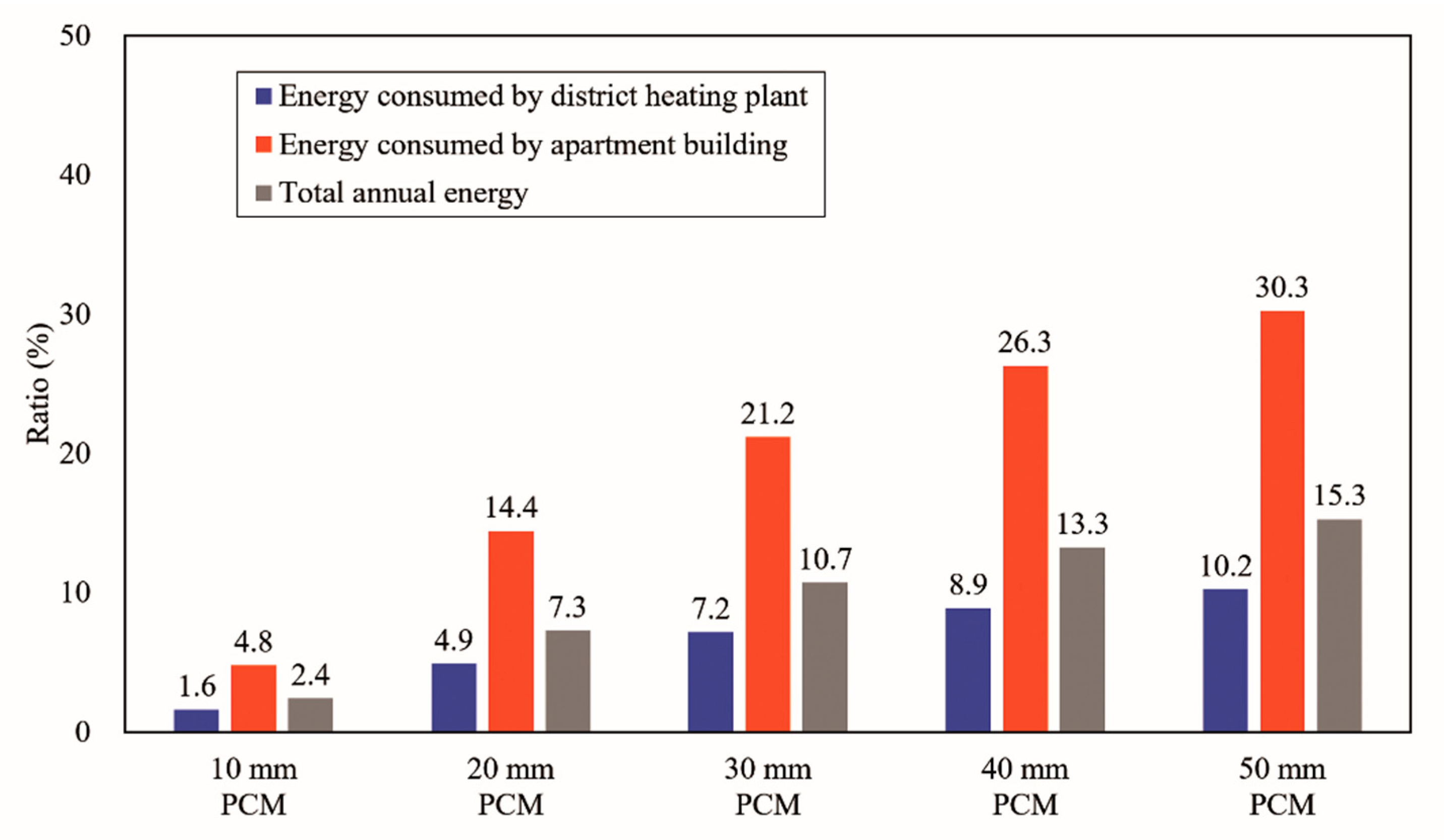
Figure 14 compares the annual heating energy consumptions on the second story of the apartment building, where the thickness of the PCM is varied from 10 to 50 mm. According to the analysis results described earlier, the annual heating energy consumptions in the cases with the existing system and 10 mm PCM were 165.6 and 161.5 MWh, respectively. When the thickness of the PCM was increased to 20, 30, 40, and 50 mm, the heating energy consumptions were 153.5, 147.8, 143.6, and 140.3 MWh, respectively. As shown in Figure 15, the total heating energy reduction ratio was 2.4% in the building that applied the 10 mm PCM, and it ranged from 7.3% to 15.3% when the thickness of the PCM increased from 20 mm to 50 mm. This is because the discharge of latent heat and sensible heat increased with the capacity of the PCM. In other words, the use of hot water was reduced as the duration in which floor surface temperature remained constant was extended by the PCM. Therefore, it can be judged that the energy saving performance of the floor can be improved as the capacity of PCM increases in the PCM radiant floor heating system. However, as the proposed PCM radiant floor heating system is designed as the floor structure for the middle stories of apartment buildings, it must also prevent interlayer noise [12]. Therefore, when ALC is replaced by PCMs in the future, it is necessary to examine whether the new system can exhibit the same noise performance as the existing system.
5. Conclusions
This study aimed to evaluate the indoor environment and energy saving performance for the PCM radiant floor heating system based on the wet construction method and hot water. The results of this study are summarized as follows:
- When the radiant floor heating system with the 10 mm PCM was applied to an apartment building, the indoor air temperature ranged from 14.2 to 18.5 °C with a control error of ± 1 °C for the simulation days including heating and non-heating periods. However, considering the heating period only, the indoor air temperature was maintained at around 18 °C. Furthermore, the floor surface temperature by the PCM radiant floor heating system ranged from 27.3 to 30.1 °C with a control error of ± 1 °C in the heating and non-heating periods. On the other hand, considering the heating period only, the floor surface temperature was maintained at approximately 30 °C.
- Consequently, the indoor air and floor surface temperatures were nearly maintained at each set-point for the heating period by applying to the PCM radiant floor heating system to the apartment building. However, in the case of the indoor air temperature, it was around 2 °C lower than the set-point of 20 °C. As a result, if the indoor air temperature is maintained at lower or higher temperatures than the set-point, it can be solved by adjusting the floor surface temperature through the changes of the hot-water temperature or the PCM melting point.
- District heating plant was applied to supply the hot water to the PCM radiant floor heating system for the heating period, and the annual energy consumption was analyzed by connecting the district heating plant and the PCM radiant floor heating system. While the annual energy consumed by the existing radiant floor heating system was found to be 165.6 MWh, the annual energy consumed by the PCM radiant floor heating system was 161.5 MWh. Therefore, it revealed that the radiant floor heating system with 10 mm PCM can reduce the energy consumption of around 2.4 % annually as compared with the existing system.
- The thickness of the PCM was increased to 20–50 mm to improve the energy performance of the PCM radiant floor heating system. As a result, the annual energy saving ratio was increased from 7.3 to 15.3 %. This is because the discharge of latent heat and sensible heat increased with the capacity of the PCM. However, when the proposed system is utilized as the floor structure on the middle stories of apartment buildings, the change in noise performance caused by replacing the existing ALC with PCM must be examined.
Along with the previous studies, this study presented the results on the design, structure, optimal hot-water temperature, and energy performance for the PCM radiant floor heating system based on the wet construction method and hot water. In future, an experimental test will be conducted to analyze the actual heating energy consumption by applying the proposed system to actual apartment buildings or test houses.
Author Contributions
Funding acquisition, S.B. and S.K.; project administration, S.B. and S.K.; writing—original draft, S.B.; writing—review & editing, S.B.
Funding
This research was funded by the Basic Science Research Program through the National Research Foundation of Korea (NRF) funded by the Ministry of Education (grant number: 2018R1D1A1B07048848).
Conflicts of Interest
The authors declare no conflict of interest.
References
- Alvaro, D.G.; Cabeza, L.F. Phase change materials and thermal energy storage for buildings. Energy Build. 2015, 103, 414–419. [Google Scholar] [CrossRef] [Green Version]
- Lin, K.; Zhang, Y.; Xu, X.; Di, H.; Yang, R.; Qin, P. Modeling and simulation of under-floor electric heating system with shape-stabilized PCM plates. Build. Environ. 2004, 39, 1427–1434. [Google Scholar] [CrossRef]
- Lin, K.; Zhang, Y.; Di, H.; Yang, R. Study of an electrical heating system with ductless air supply and shape-stabilized PCM for thermal storage. Energy Convers. Manag. 2007, 48, 2016–2024. [Google Scholar] [CrossRef]
- Jin, X.; Zhang, X. Thermal analysis of a double layer phase change material floor. Appl. Therm. Eng. 2011, 31, 1576–1581. [Google Scholar] [CrossRef]
- Huang, K.; Feng, G.; Zhang, J. Experimental and numerical study on phase change material floor in solar water heating system with a new design. Sol. Energy 2014, 105, 126–138. [Google Scholar] [CrossRef]
- Barzin, R.; Chen, J.J.J.; Young, B.R.; Farid, M.M. Application of PCM underfloor heating in combination with PCM wallboards for space heating using price based control system. Appl. Energy 2015, 148, 39–48. [Google Scholar] [CrossRef]
- Cheng, W.; Xie, B.; Zhang, R.; Xu, Z.; Xia, Y. Effect of thermal conductivities of shape stabilized PCM on under-floor heating system. Appl. Energy 2015, 144, 10–18. [Google Scholar] [CrossRef]
- Zhou, G.; He, J. Thermal performance of a radiant floor heating system with different heat storage materials and heating pipes. Appl. Energy 2015, 138, 648–660. [Google Scholar] [CrossRef]
- Zhang, Y.; Chen, C.; Jiao, H.; Wang, W.; Shao, Z.; Qi, D.; Wang, R. Thermal performance of new hybrid solar energy-phase change storage-floor radiant heating system. Procedia Eng. 2016, 146, 89–99. [Google Scholar] [CrossRef]
- Plytaria, M.T.; Tzivanidis, C.; Bellos, E.; Antonopoulos, K.A. Energetic investigation of solar assisted heat pump underfloor heating systems with and without phase change materials. Energy Convers. Manag. 2018, 173, 626–639. [Google Scholar] [CrossRef]
- Negishi Ltd. PCM Underfloor Heating System. 2018. Available online: http://www.negishi-nhm.com/html/yukadan_P_sekou.html (accessed on 19 January 2019).
- Baek, S.; Park, J. Proposal of a PCM underfloor heating system using a web construction method. Int. J. Polym. Sci. 2017, 2017, 2693526. [Google Scholar] [CrossRef]
- Baek, S.; Yoon, S.; Park, J. Analysis on effects of melting points to apply to PCMs in radiant floor heating systems using wet construction and hot water. J. Korean Soc. Living Environ. Syst. 2018, 25, 1–6. [Google Scholar] [CrossRef]
- Baek, S.; Kim, S. Determination of optimum hot-water temperatures for PCM radiant floor-heating systems based on the wet construction method. Sustainability 2018, 10, 4004. [Google Scholar] [CrossRef]
- Thomson Reuters LAWnB. Rules for Building Equipment Standards. Available online: http://www.lawnb.com/Info/ContentView?sid=L006A907EBEE7A64 (accessed on 19 January 2019).
- Rubitherm Ltd. Phase Change Material. Available online: http://www.rubitherm.eu/en/index.php/productcategory/organische-pcm-rt (accessed on 19 January 2019).
- U.S. Department of Energy. EnergyPlus Version 8.7.0. Documentation: Getting Started. Available online: https://energyplus.net/documentation (accessed on 19 January 2019).
- U.S. Department of Energy. EnergyPlus Version 8.7.0. Documentation: Input Output Reference. Available online: https://energyplus.net/documentation (accessed on 19 January 2019).
- U.S. Department of Energy. EnergyPlus Version 8.7.0. Documentation: Engineering Reference. Available online: https://energyplus.net/documentation (accessed on 19 January 2019).
- Thomson Reuters LAWnB. Enforcement Decree of the Building Act. Available online: http://www.lawnb.com/Info/ContentView?sid=L000DFE68B75F986_0 (accessed on 19 January 2019).
- The Korean Solar Energy Society. Korea Standard Weather Data: Seoul. Available online: http://www.kses.re.kr/data_06/list_hi.php (accessed on 19 January 2019).
- Korean Institute of Architectural Sustainability Environment and Building System. Building Airtightness Critical. Available online: http://www.kiaebs.org/servlet/Aik_FileDownload?filecode=06&filename=kiaebs157476659.pdf&filename2=01%20KIAEBS%20C-1(2013)%20%B0%C7%C3%E0%B9%B0%C0%C7%20%B1%E2%B9%D0%BC%BA%B4%C9%20%B1%E2%C1%D8.pdf (accessed on 19 January 2019).
- Korea District Heating Corporation. Rules for Heat Energy Supply. Available online: https://www.kdhc.co.kr/content.do?cmsCd=CM3857#section3 (accessed on 19 January 2019).
- Jung, Y. An analysis on the heating load and supply water temperature for direct connection in district heating system. J. Korean Inst. Arch. Sustain. Environ. Build. Syst. 2010, 4, 165–173. [Google Scholar]
Figure 1.
Comparison between existing and phase change material (PCM) radiant floor heating systems.
Figure 1.
Comparison between existing and phase change material (PCM) radiant floor heating systems.
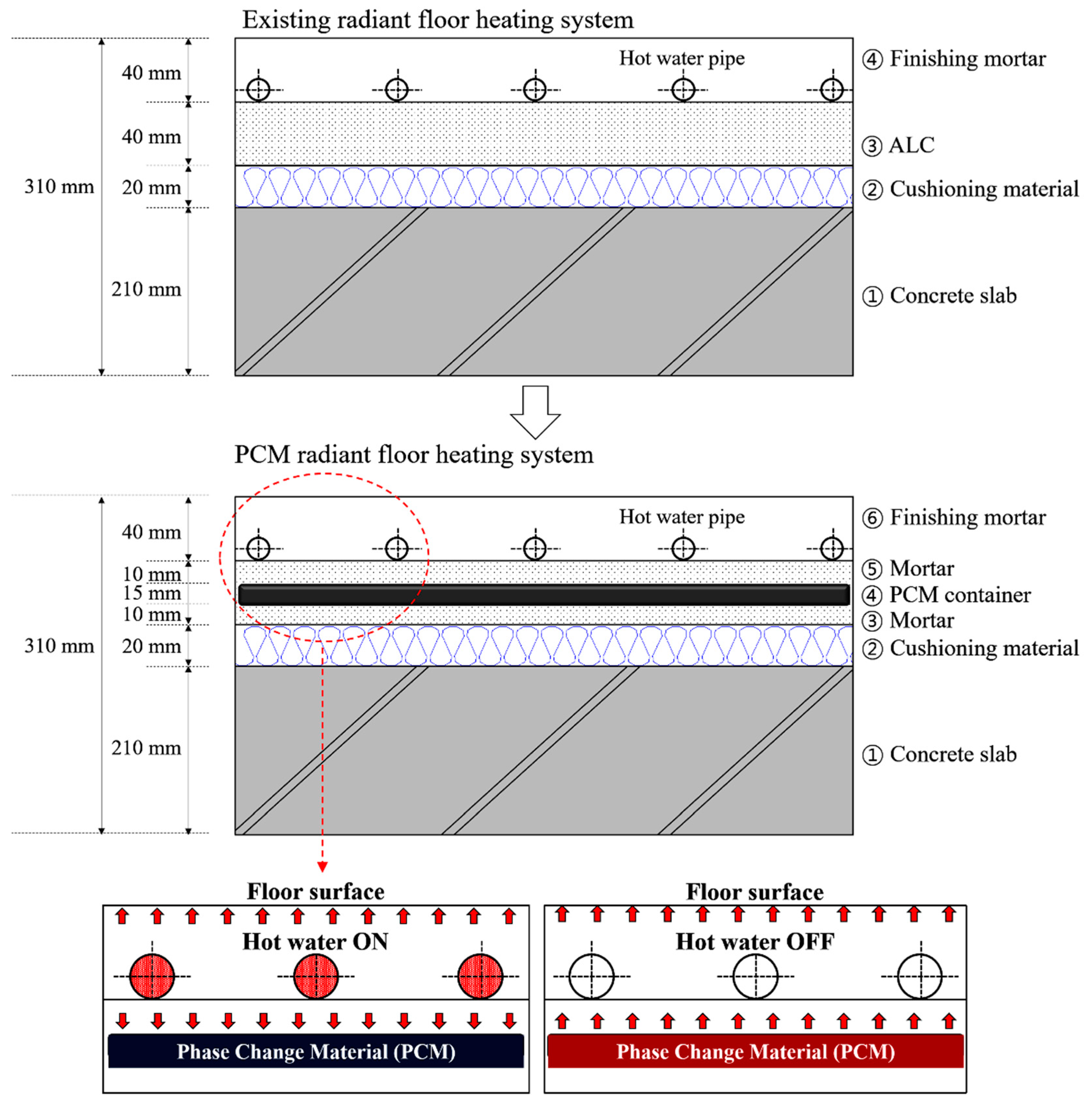
Figure 2.
The fabricating progress and the application to the floor of the PCM case.
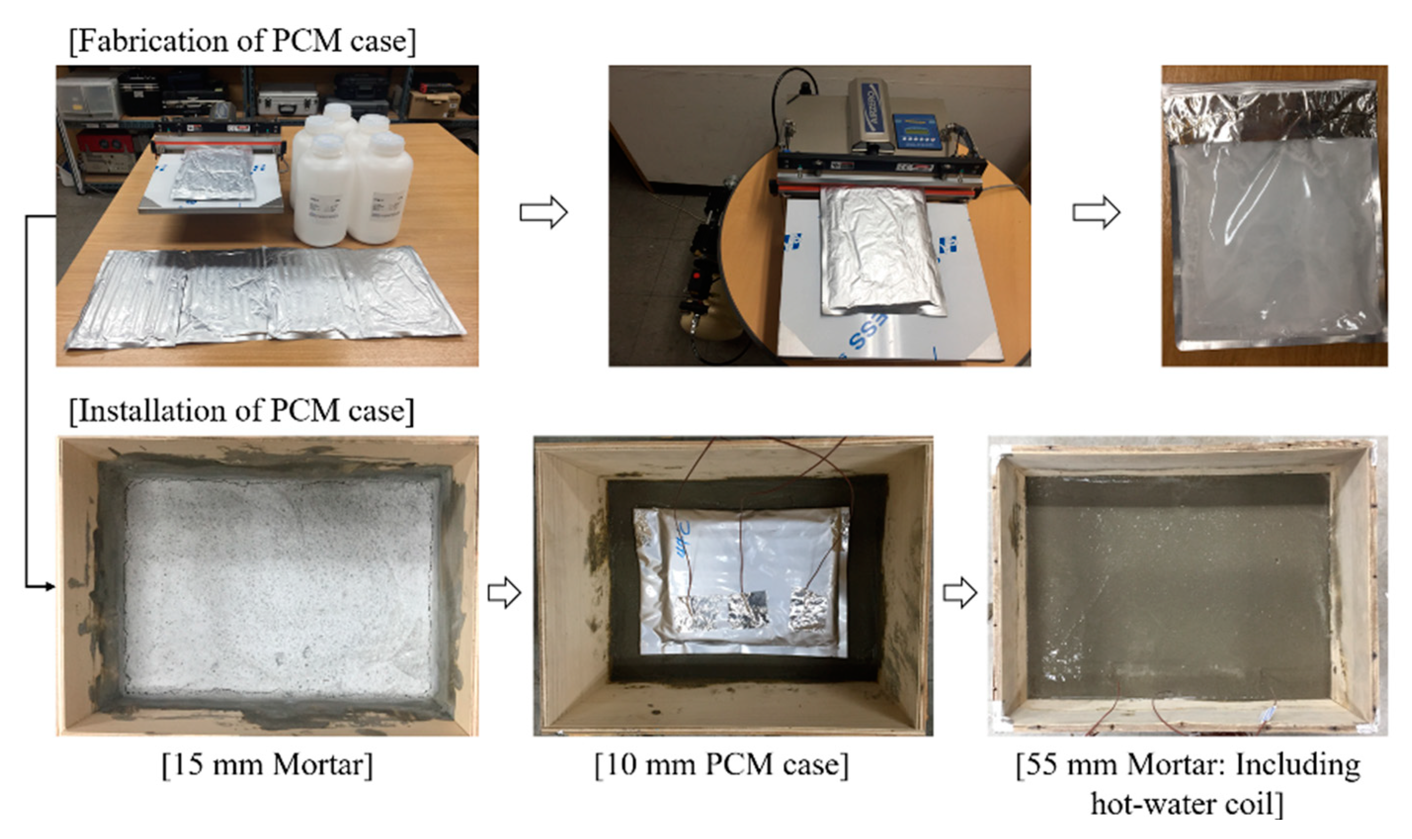
Figure 3.
The patterns of the floor surface temperature and the energy consumption in the existing radiant floor heating system.
Figure 3.
The patterns of the floor surface temperature and the energy consumption in the existing radiant floor heating system.

Figure 4.
The patterns of the floor surface temperature and the energy consumption in the PCM radiant floor heating system.
Figure 4.
The patterns of the floor surface temperature and the energy consumption in the PCM radiant floor heating system.
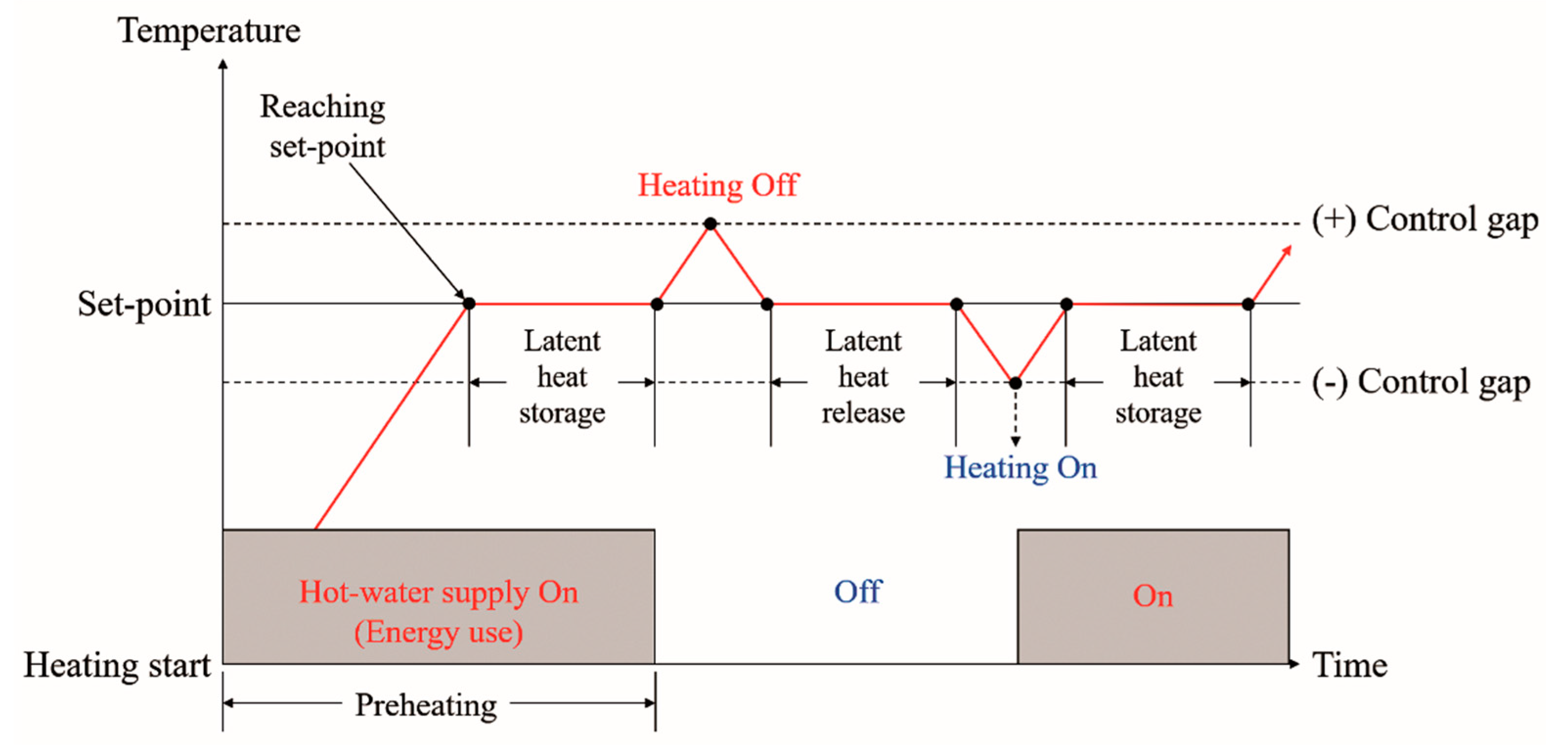
Figure 5.
Floor plan of the apartment building (left) and modeling by simulation (right).

Figure 6.
Annual Seoul standard weather data.

Figure 7.
Conception of hot-water circulation between the district heating and an apartment building.
Figure 7.
Conception of hot-water circulation between the district heating and an apartment building.
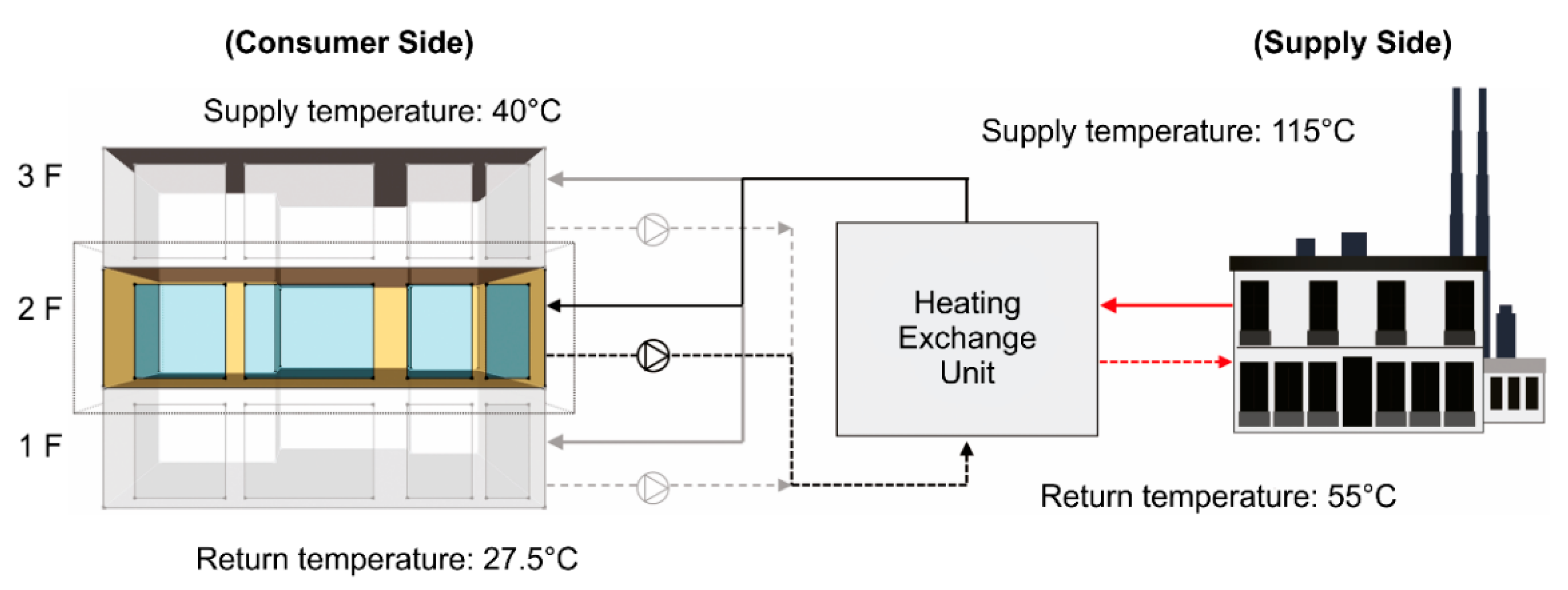
Figure 8.
Connection loop of each unit for circulation of hot water in EnergyPlus.
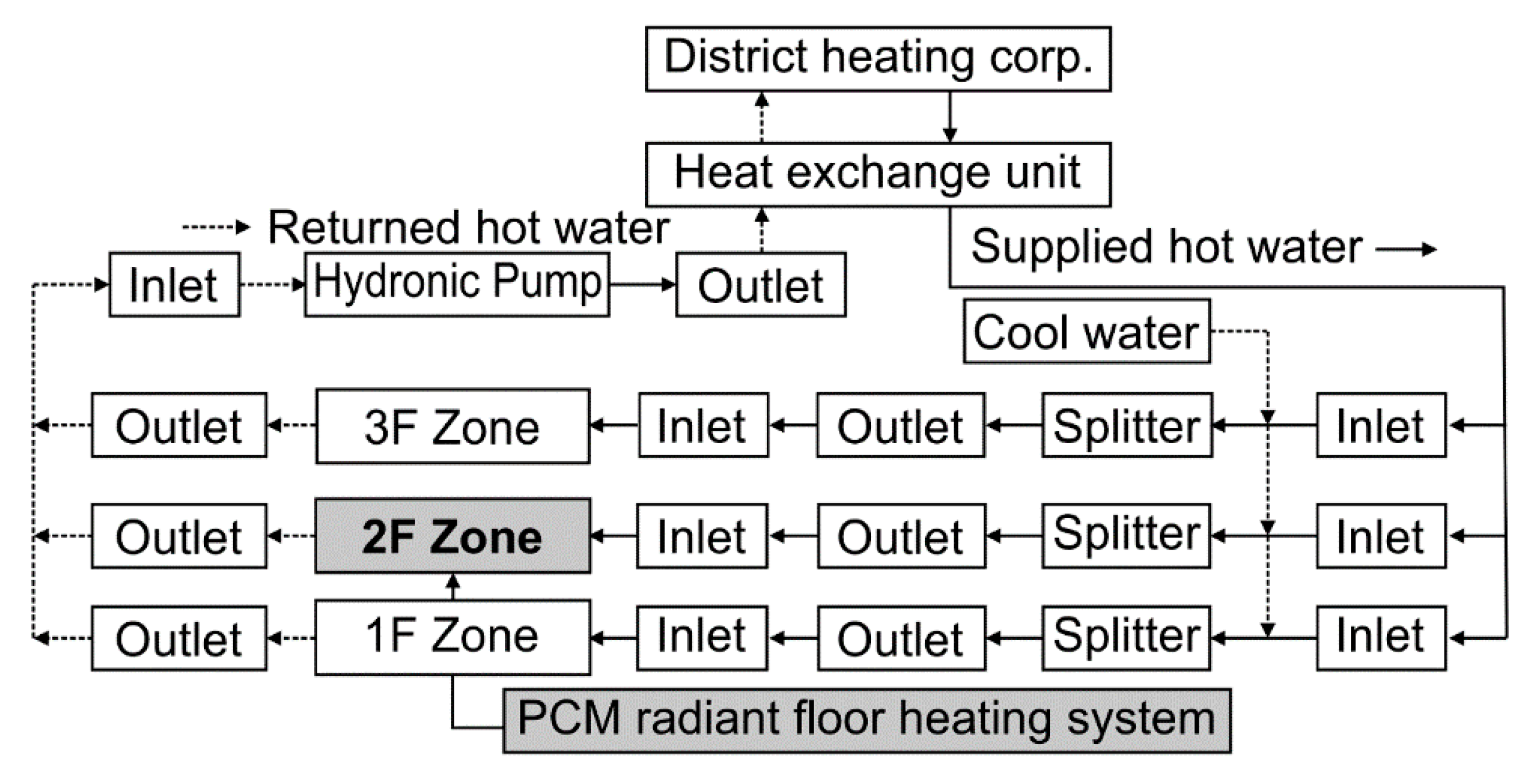
Figure 9.
Indoor air temperatures on the second stories of the apartment buildings.
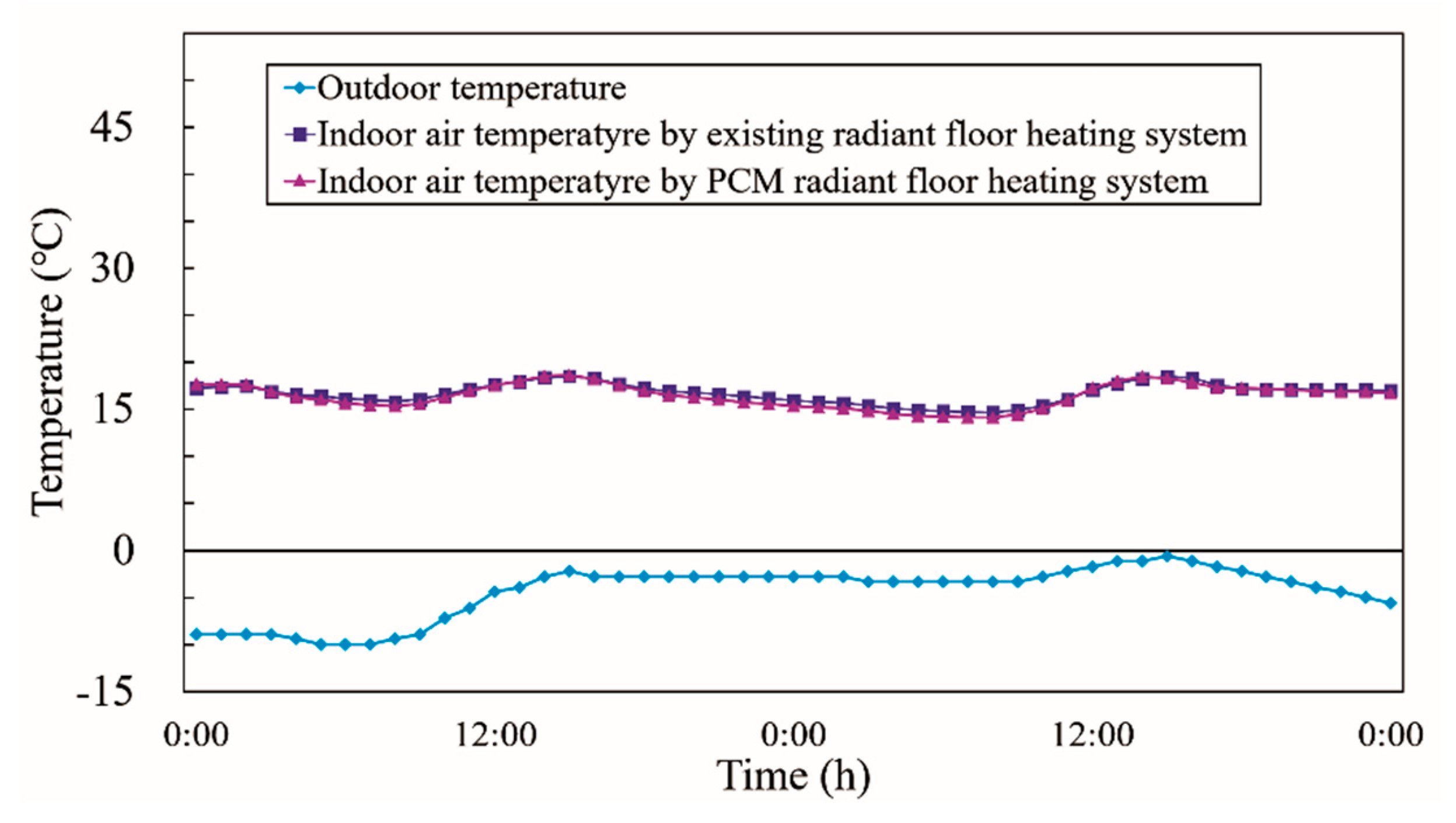
Figure 10.
Floor surface temperatures on the second stories of the apartment buildings.

Figure 11.
Annual energy consumptions of the PCM radiant floor heating systems.
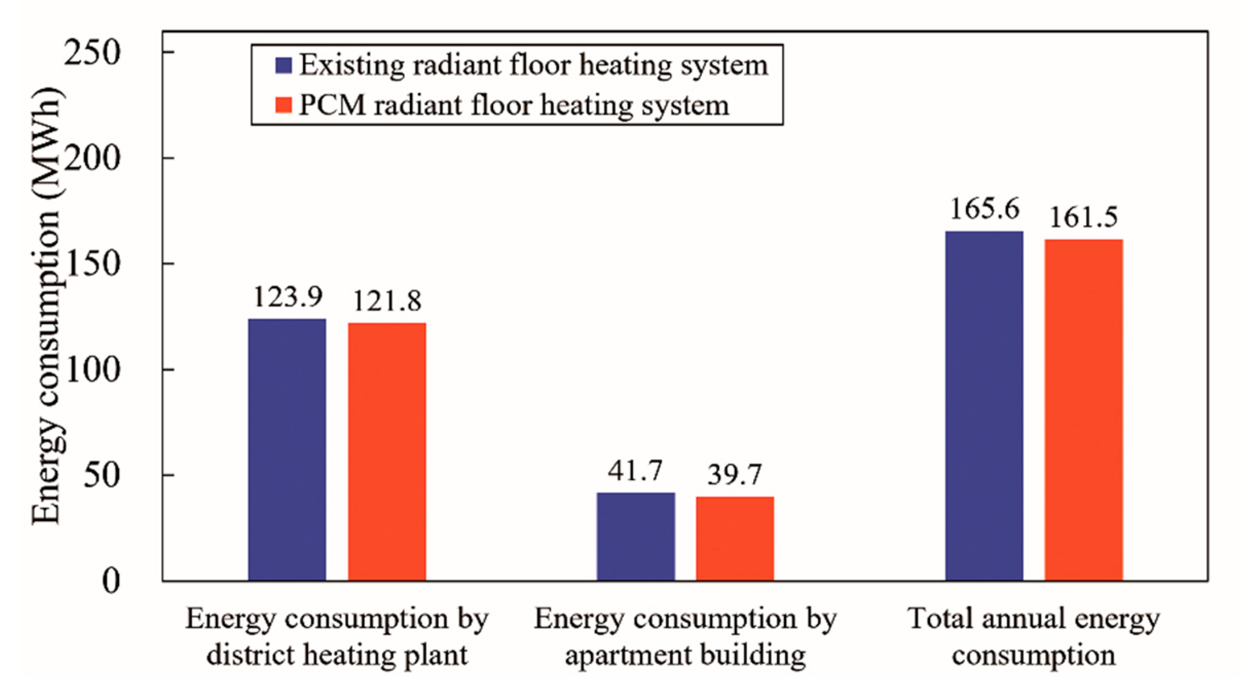
Figure 12.
Annual energy saving ratio of the PCM radiant floor heating system.

Figure 13.
Application method of 10–50 mm PCM. ALC: autoclaved lightweight concrete.

Figure 14.
Energy consumptions by the application of 10–50 mm PCM.
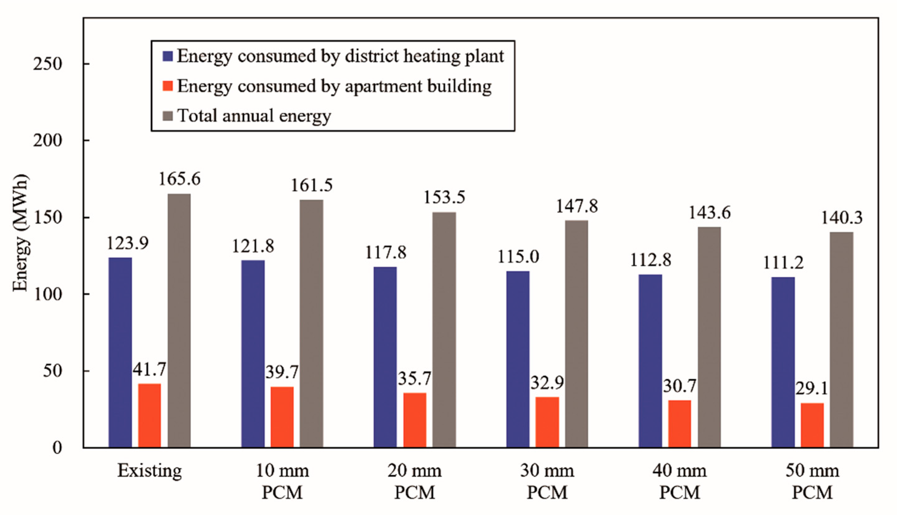
Figure 15.
Energy reduction ratios by the application of 10–50 mm PCM.

Table 1.
Previous studies on phase change material (PCM) radiant floor heating systems.
| Author and Company | Year | Type of Floor | Energy Resource | ||
|---|---|---|---|---|---|
| Study | Lin, K. et al. [2] | 2004 | Dry construction | Electrical energy | |
| Lin, K. et al. [3] | 2007 | Dry construction | Electrical energy | ||
| Jin, X. et al. [4] | 2011 | Wet construction | Hot and cold water | ||
| Huang, K. et al. [5] | 2014 | Wet construction | Solar energy & hot water | ||
| Barzin, R. et al. [6] | 2015 | Dry construction | Electrical energy | ||
| Cheng, W. et al. [7] | 2015 | Dry construction | Electrical energy | ||
| Zhou, G. et al. [8] | 2015 | Dry construction | Hot water | ||
| Zhang, Y. et al. [9] | 2016 | Dry construction | Solar energy & hot water | ||
| Plytaria, M. T. et al. [10] | 2018 | Wet construction | Solar energy & hot water | ||
| Company | Negishi corporation Ltd. [11] | Type 1 | 2018 | Dry construction | Solar energy |
| Type 2 | 2018 | Dry construction | Solar energy | ||
| Type 3 | 2018 | Wet construction | Electrical energy | ||
Table 2.
The thermal characteristics of the PCM with the melting point of 44 °C.
| PCM Type | Melting Point | Specific Heat (Cp) | Density (ρ) | Conductivity (k) |
|---|---|---|---|---|
| (°C) | (J/kg·°C) | (kg/m3) | (W/m·°C) | |
| Organic material | 41–44 | 2000 | 800 | 0.2 |
Table 3.
Heat capacity of PCM at different temperatures [16].
Table 3.
Heat capacity of PCM at different temperatures [16].
| Temperature (°C) | Capacity (J/kg) |
|---|---|
| 35 | 2000 |
| 36 | 2000 |
| 37 | 3000 |
| 38 | 2000 |
| 39 | 3000 |
| 40 | 6000 |
| 41 | 43,000 |
| 42 | 53,000 |
| 43 | 107,000 |
| 44 | 25,000 |
| 45 | 2000 |
| 46 | 2000 |
| 47 | 2000 |
| 48 | 2000 |
| 49 | 2000 |
| 50 | 2000 |
Table 4.
Structures and characteristics of building envelopes [20].
Table 4.
Structures and characteristics of building envelopes [20].
| Section | Material | Thickness | U-value (c) | |
|---|---|---|---|---|
| Material | Total | |||
| (mm) | (mm) | (W/m2⋅K) | ||
| 1st-story floor structure | Concrete slab | 210 | 415 | 0.1741 |
| Insulating material | 120 | |||
| ALC | 40 | |||
| Hot-water coil | 15 | |||
| Mortar | 40 | |||
| Finishing material | 5 | |||
| 2nd-story floor structure | Gypsum board | 10 | 425 | 0.1534 |
| Air cavity | 100 | |||
| Concrete slab | 210 | |||
| Insulating material | 20 | |||
| ALC (a) | 15 | |||
| PCM (b) | 10 | |||
| ALC | 15 | |||
| Hot-water coil | 15 | |||
| Mortar | 40 | |||
| Finishing material | 5 | |||
| 3rd-story floor structure | Gypsum board | 10 | 425 | 0.1530 |
| Air cavity | 100 | |||
| Concrete slab | 210 | |||
| Insulating material | 20 | |||
| ALC | 40 | |||
| Hot-water coil | 15 | |||
| Mortar | 40 | |||
| Finishing material | 5 | |||
| 3rd-story roof structure | Gypsum board | 10 | 490 | 0.1105 |
| Air cavity | 100 | |||
| Insulating material | 90 | |||
| Concrete slab | 210 | |||
| Mortar | 80 | |||
| Exterior wall | Concrete wall | 180 | 310 | 0.2005 |
| Insulating material | 120 | |||
| Gypsum board | 10 | |||
(a) Autoclaved Lightweight Concrete. (b) Phase Change Material. (c) Thermal Transmittance.
Table 5.
Structure and characteristics of the window.
| Glass | |||
| Manufacturing company | Shanghai Yaohua Pilkinton Glass Ltd. | ||
| Thickness | 6 (mm) | ||
| Thermal conductivity | 1.000 (W/m⋅K) | ||
| Exterior surface | Total wave | Transmittance | 0.246 |
| Reflectance | 0.232 | ||
| Visible wave | Transmittance | 0.313 | |
| Reflectance | 0.302 | ||
| Surface emissivity | 0.840 | ||
| Interior surface | Total wave | Transmittance | 0.246 |
| Reflectance | 0.218 | ||
| Visible wave | Transmittance | 0.131 | |
| Reflectance | 0.106 | ||
| Surface emissivity | 0.540 | ||
| Insulating gas | |||
| Gas type | Argon (100% pure) | ||
| Thickness | 12 (mm) | ||
| Thermal conductivity | 0.016348 (W/m⋅K) | ||
| Specific heat | 521.929 (J/kg·°C) | ||
| Density | 1.782282 (kg/m3) | ||
| Viscosity | 0.000021 (kg/m·s) | ||
| Prandtl number | 0.6705 | ||
| Triple pane glazing system | |||
| Total thickness | 42 (mm) | ||
| Total U-value | 1.208 (W/m2⋅K) | ||
| Frame system | |||
| Material | Aluminum | ||
| Filled insulating material | Urethane | ||
| Width | 300 (mm) | ||
| Projected length from glazing | 129 (mm) | ||
| Entire window system | |||
| Exterior surface heat transfer coefficient | 23.3 (W/m2⋅K) | ||
| Interior surface heat transfer coefficient | 9.1 (W/m2⋅K) | ||
| Total U-value of window system | 1.208 (W/m2⋅K) | ||
Table 6.
Schedules of daily occupants, light, infiltration, and ventilation.
| Factor | Time Interval | Unit | Value |
|---|---|---|---|
| Occupant | 00:00–08:00 | person | 4 |
| 08:00–18:00 | 0 | ||
| 18:00–24:00 | 4 | ||
| Light | 00:00–05:00 | Fraction | 0.1 |
| 05:00–08:00 | 1.0 | ||
| 08:00–18:00 | 0.0 | ||
| 18:00–22:00 | 1.0 | ||
| 22:00–24:00 | 0.1 | ||
| Infiltration | 00:00–24:00 | air-change/h | 3.0 |
| Ventilation | 00:00–08:00 | air-change/h | 0.5 |
| 08:00–18:00 | 0.0 | ||
| 18:00–24:00 | 0.5 |
Table 7.
Performances and characteristics of units for hot-water circulation.
| Unit | Value | |
|---|---|---|
| Hydronic-pump pipe diameter | 0.015 | (m) |
| Hydronic-pump surface heat loss | Adiabatic | |
| Hydronic-pump flow rate | Autosize | |
| Hydronic-pump head pressure | 200,000 | (Pa) |
| Hydronic-pump motor efficiency | 0.9 | |
| Hydronic-pump control type | Intermittent | |
| Hot-water pipe diameter | 0.015 | (m) |
| Hot-water pipe surface heat loss | Adiabatic | |
| Cool-water pipe diameter | 0.015 | (m) |
| Cool-water pipe surface heat loss | Adiabatic | |
| Splitter flow rate control | Autosize | |
Table 8.
Schedules of set points for indoor air and the floor surface.
| Factor | Time Interval | Value |
|---|---|---|
| Indoor temperature | 00:00–08:00 | 20 °C |
| 08:00–18:00 | 10 °C | |
| 18:00–00:00 | 20 °C | |
| 18:00-24:00 | 20 °C | |
| Floor surface temperature | 00:00–08:00 | 30 °C |
| 08:00–18:00 | 15 °C | |
| 18:00–00:00 | 30 °C | |
| 18:00-24:00 | 30 °C |
© 2019 by the authors. Licensee MDPI, Basel, Switzerland. This article is an open access article distributed under the terms and conditions of the Creative Commons Attribution (CC BY) license (http://creativecommons.org/licenses/by/4.0/).
Share and Cite
MDPI and ACS Style
Baek, S.; Kim, S. Analysis of Thermal Performance and Energy Saving Potential by PCM Radiant Floor Heating System based on Wet Construction Method and Hot Water. Energies 2019, 12, 828. https://doi.org/10.3390/en12050828
AMA Style
Baek S, Kim S. Analysis of Thermal Performance and Energy Saving Potential by PCM Radiant Floor Heating System based on Wet Construction Method and Hot Water. Energies. 2019; 12(5):828. https://doi.org/10.3390/en12050828
Chicago/Turabian StyleBaek, Sanghoon, and Sangchul Kim. 2019. "Analysis of Thermal Performance and Energy Saving Potential by PCM Radiant Floor Heating System based on Wet Construction Method and Hot Water" Energies 12, no. 5: 828. https://doi.org/10.3390/en12050828
Note that from the first issue of 2016, this journal uses article numbers instead of page numbers. See further details here.