Multi-Level Open End Windings Multi-Motor Drives
by
 , and
, and
Salvatore Foti
1,* ,
,
Antonio Testa
1,
Salvatore De Caro
1,
Tommaso Scimone
1,
Giacomo Scelba
2 and
Giuseppe Scarcella
2 1
DI, University of Messina, 98122 Messina, Italy
2
DIEEI, University of Catania, 95131 Catania, Italy
*
Author to whom correspondence should be addressed.
Energies 2019, 12(5), 861; https://doi.org/10.3390/en12050861
Submission received: 20 December 2018
/
Revised: 23 February 2019
/
Accepted: 25 February 2019
/
Published: 5 March 2019
(This article belongs to the Special Issue Multilevel Converters: Analysis, Modulation, Topologies, and Applications)
Abstract
:A multi-level open-end winding converter topology for multiple-motor drives is presented featuring a main multi-level inverter processing the power delivered to the motors and an active filter based on an auxiliary two-level inverter. The main inverter operates at the fundamental frequency in order to achieve low switching power losses, while the active filter is Pulse Width Modulation (PWM) operated to suitably shape the motor currents. The proposed configuration features less phase current distortion than conventional multi-level inverters operating at the fundamental frequency, while achieving a higher efficiency compared to PWM multi-level inverters. Experimental results confirm the effectiveness of such a configuration on both multiple motors-single converter and multiple motor-multiple converter drives.
1. Introduction
A Multiple Motor Drive (MMD) is composed of some electric motors sharing the load torque [1,2,3,4,5]. Such a configuration costs less than a set of single motor drives, as some resources are shared between the units. Further, compared to a single drive, it is easily expandable by adding new units, moreover, the intrinsic redundancy may be used to mitigate the effects of some kinds of converter and motor faults. MMD are common in paper and textile industry and ironworks, as well as in several industry applications demanding synchronization between two or more axes, high levels of reliability and/or easy expandability. MMD systems can be grouped into two classes, namely: Multiple Motors Fed by a Single Multi-level Converter (MMSC) and Multiple Motors Fed by Multiple Multi-level Converters (MMMC). A single inverter on MMSC delivers power to all the machines, thus leading to only an approximatively proportional load sharing. On MMMC a common DC bus supplies a set of inverters, each one powering a single motor. In this case, the torque produced by each motor can be independently controlled, while retaining a common power entry and braking system.
Induction Motor (IM) based MMMCs are frequently used on rail mounted, or rubber tired, gantry cranes, equipping hoist, trolley and leg drives [6,7,8]. On leg drives MMMCs provide the ground to cope with different wheel diameter, unequal wheels’ adhesion and slipping of transmission devices. MMDs also often equip electric locomotives, powering the axles through spur gearings [9,10,11,12]. Dual-Voltage Source Inverter (VSI)/Dual-IM and Mono-VSI/Dual-IM configurations are used with induction motors. The first, being of the MMMC type, comprises two induction motors supplied through two power converters. Such a configuration features a higher level of robustness toward inverter faults. Moreover, critical operations caused by pantograph detachment, loss of wheel adherence and stick-slip perturbation may be faced thanks to a fully independent control of the torque delivered by single machines. In recent years, MMMC has also become a viable alternative to single drives on powertrains of electrical and hybrid vehicles, featuring higher flexibility, reliability and transmission efficiency, while helping to increase the available inner space [13,14].
A straightforward way to control the speed of a MMMC is based on the common speed reference technique, providing a common speed reference signal to the speed controller of each unit. A torque follower control approach is however preferable, due to concerns regarding the control precision and system flexibility. According to such a technique, as shown in Figure 1, a single speed command is provided to a master unit, which in turns sends the torque references to the other drives [6]. Torque and flux regulation on single units is generally based on the traditional Indirect Field Oriented Control (IFOC) technique or Direct Torque Control strategy.
In recent years, Multi-Level Inverters (MLIs) have been introduced on multi-motor drives. in order to generate almost sinusoidal output voltages using low frequency switching power devices, thus achieving high efficiency and electromagnetic compatibility. In addition, power devices are tasked with withstanding a fraction of the total DC input voltage, resulting in a remarkable reduction of dv/dt stresses and switches voltage ratings. However, in order to achieve a comparable phase current Total Harmonic Distortion (THD), MLI topologies working at low switching frequency could require many more power devices than conventional Pulse Width Modulation (PWM) operated bridge inverters. Cost concerns lead to limitation of the number of power devices, resulting in torque ripple and additional losses. These can be addressed by selective harmonic elimination or PWM techniques, as well as, by the addition of line reactors and tuned harmonic filters. Active power filters may also be exploited as they are able to provide a more flexible and effective attenuation of current harmonics [15,16,17,18,19,20,21,22,23,24].
An Open-end Winding (OW), multi-level, configuration for MMD applications is proposed in this paper; it features null neutral point fluctuations, low phase current ripple and improved DC bus voltage utilization [25,26,27,28,29]. A distinctive characteristic of the proposed configuration is the asymmetry, because that the two inverters are not of the same type and only one of the two provides power to the motors. In fact, a main multi-level inverter processes the power delivered to the motors, while an active filter, based on an auxiliary two-level inverter (TLI), shapes the phase current. Moreover, the main inverter operates at the fundamental frequency in order to achieve low switching power losses, while the active filter is PWM operated. Finally, the DC bus voltage of the two-level inverter is remarkably lower than that of the main inverter [30,31,32,33,34,35,36]. The proposed MMD OW configuration features a higher global efficiency and lower current THD than an equivalent PWM operated multi-level inverter for multi-motor drives [37], exploiting a specific control strategy combining low switching frequency modulation on the MLI and high frequency PWM on the TLI. Finally, it can be used either on either multiple motors-single converter or multiple motor-multiple converter drives.
2. Open Winding Multiple Motors Fed by a Single Multi-Level Converter—MMSC
Although the proposed approach can be applied to a system composed of an arbitrary number of machines, a system comprising only two identical induction motors, sharing the total load torque, is considered for simplicity. The proposed MMSC structure is shown in Figure 2; the stator windings of the two OW induction motors IM1 and IM2, are parallel connected to a MLI and a TLI, but only the first actually delivers active power to both motors, the second being operated as an active filter. This makes the proposed configuration different from most common OW motor drives, where the power supplied to the motors is evenly shared between the two inverters. The TLI, which supplies a null average power to the motors, can be supplied through a floating capacitor, avoiding the need for an additional power source and also making the two DC voltage sources VDC′ and VDC″ independent. The motors are assumed to be speed controlled through an IFOC technique, but the load sharing between the motors cannot be managed. The output phase voltage of an MLI may take n different levels. The magnitude of each level is generally defined as the voltage across the mid-point of the DC bus and the output phase terminal. The number of possible voltage levels is generally odd, including a zero level and n − 1 non-zero levels and each level is identified by the value of the coefficient l′ = 0, 1, 2, …, n − 1. The i-phase MLI output voltage VMLI_stepi is thus given by:
In the same way, the i-phase TLI output voltage VTLIi is given by:
where l″ = 0, 1 is the i-phase TLI actual output voltage level.
The voltage Vmi across a generic ‘i’ motor phase winding, is finally given by:
where Vn′n″ is the voltage across the mid points n′ and n″ of the two DC buses, which is given by:
The phase voltage Vmi takes the zero level and further 4(n + 1) non-zero levels when VDC″ = VDC′/[2(n − 1)], while, some additional non zero levels become available if VDC″ < VDC′/[2(n − 1)] [31].
The voltage levels which the proposed asymmetrical hybrid multilevel inverter configuration may take are more numerous than those of conventional Neutral Point Clamped (NPC) or Flying Capacitor (FC) MLI topologies with the same amount of power switches. In other words, the same phase voltage THD can be achieved with the proposed MMSC configuration using fewer power devices. Moreover, the proposed configuration features a switching frequency which is that of the TLI, although the main inverter switches at the fundamental frequency [37]. This leads to use power devices optimized for low switching frequency operation (i.e., featuring a low on-state voltage drop) in the MLI, and power devices suitable for high switching frequency in the TLI.
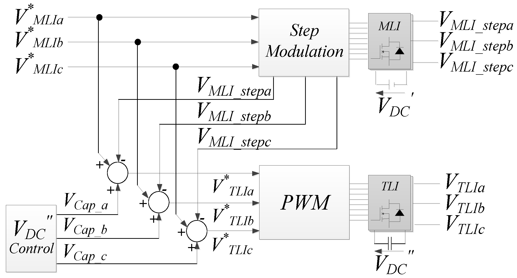
A suitable motor phase voltage modulation strategy was formulated taking into account the specific features of the proposed topology, according to the scheme in Figure 3.
The TLI is tasked with compensating low frequency phase voltage harmonics generated by the MLI, which is step driven to reduce the switching power losses. Unwanted low frequency voltage harmonics can be suppressed by setting the voltage reference V*TLIi of the TLI to:
where: V*MLIi is the fundamental harmonic of the ith motor phase reference voltage V*MLI_stepi. Both quantities are depicted in Figure 4 for the case of a seven-level VMLI_stepi waveform.
The voltage ratio KV = VDC″/VDC′ is a key parameter, because it impacts on the number of inverter voltage levels, on the THD of phase voltages and currents, on the maximum motor phase voltage amplitude and finally, on the ratings of TLI power devices.
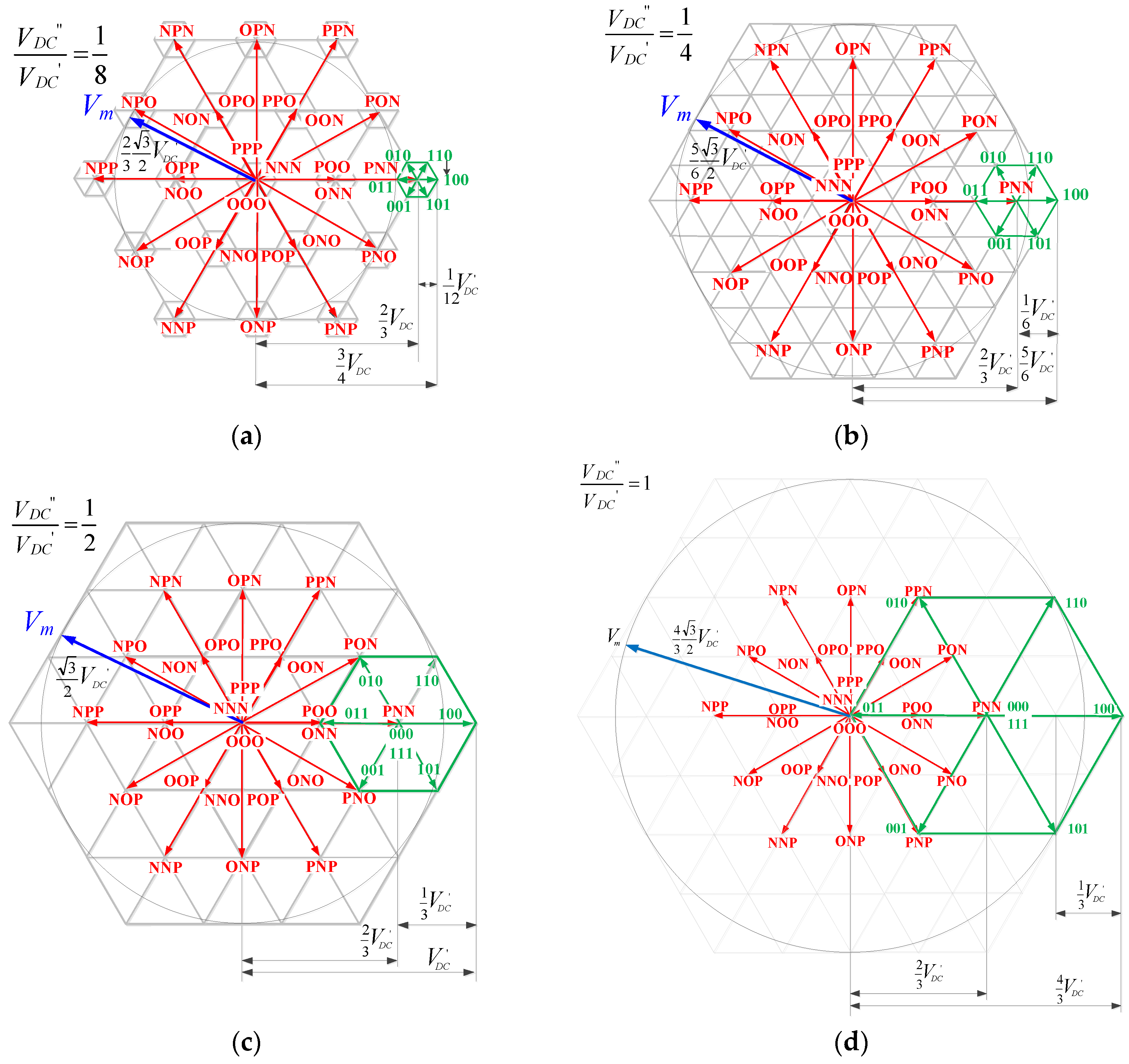
The phase voltage Vmi is the difference between VMLIi and VTLIi, hence, its space vector diagram can be obtained by combination of the voltage space vector diagrams of the MLI and TLI. The simplest MMSC structure which can be obtained with the proposed approach consists of a Three-Level inverter (3LI) and a TLI (3LI+TLI).
The phase voltage of each inverter leg of the 3LI can assume three statuses namely: P, O and N. P denotes that the inverter phase voltage VMLIi = VDC′, while O indicates that VMLIi = 0, and N that VMLIi = −VDC′. The 3LI topology is basically composed of two cells, each one supplied at VDC′/2, hence each leg may take three switching states, resulting in 33 = 27 possible inverter switching state combinations. Each space vector can be categorized into zero voltage, small voltage, medium voltage and large voltage on the basis of its magnitude. These are tabulated in Table 1. The TLI instead features 23 = 8 inverter states, leading to 7 voltage vectors. As shown in Figure 5, the 3LI+TLI voltage space vector diagram is obtained by composition of the voltage space vector diagrams of the TLI and the 3LI. The number of available voltage vectors and voltage levels depends on KV, as listed in Table 2, affecting both the THDV and the peak amplitude Vmpk of the phase voltage Vmi. In particular, Vmpk increases with KV, while a minimum THDV is achieved for VDC″ = VDC′/[(n − 1)], [24], thus, the considered 3LI+TLI system gets the minimum THDV for VDC″ = VDC′/2. However, Vmpk maximization must be also taken into consideration, thus, a useful figure of merit in determining the optimal value of KV is Kp = Vmpk/(VDC′ × THDV), which, according to Table 3, is maximized when VDC″ = VDC′/2. When VDC″ is reduced below VDC′/2, Kp and Vmpk decrease, while the number of voltage levels and voltage vectors increases, as well as THDV. However, the voltage rating of TLI power devices is lowered. For KV = 1/8, the 3LI+TLI is equivalent to conventional six-level NPC or FC inverter structures, which however require six more power devices. By setting VDC″ over VDC′/2, a higher Vmpk is obtained, while the number of voltage levels and voltage vectors is lowered, worsening THDV and Kp. Moreover, when VDC″ = VDC′, the voltage rating of the TLI switches becomes equal to that of MLI devices.
According to the proposed approach no active power is delivered to the two IM motors from the TLI. In practice, power devices and motors power losses in the TLI would cause a progressive discharge of the floating capacitor of the TLI DC-bus. Being floating, such a capacitor can only be charged by diverting to it a small quantity of the active power delivered by the MLI to the motors [32,33,34,35,36,37,38,39,40,41,42,43,44]. As shown in the control scheme of Figure 6, this is achieved by slightly modifying the TLI reference voltages. Specifically, two additional terms VdCap and VqCap are introduced to control the mean current flowing through the DC bus capacitor. Since the TLI is not tasked with supplying reactive power to the load, VdCap can be straightforwardly related to VqCap, by:
The active power P required to hold VDC″ constant is obtained by a PI controller processing the error between the reference DC bus voltage VDC″* and the actual voltage VDC″.
where s is the Laplace operator, and KpVDC and KiVDC are, respectively, the proportional and integral gain of the PI controller. By introducing Equation (6) into Equation (7), the dq-axes voltage reference components VqCap and VdCap are obtained:
The two additional terms are then transformed to the abc stationary frame and added to the TLI voltage references obtained from Equation (5). Due to the floating capacitor recharging, the phase current typically increases by less than 1.5% of the rated current. The considered 3LI+TLI topology requires a specific control system which is schematized in Figure 6. It consists of two subsystems, acting on the two inverters. The MLI is voltage controlled, thus, the q, d axes voltage references VdqMLI* are made equal to the motors back EMF components *q and *d, which in turn are estimated by
where: ωλre is the rotor flux angular frequency, ωr is the rotor speed of the two machines, and Ls, Lr and Lm are respectively the stator, rotor and magnetizing inductances.
As shown in Figure 6, the TLI features a feedback current control, in order to improve the shape of the current waveform and the system dynamic response. The outputs V*dqTLIr_i of the TLI current control loop are transformed to the abc stationary frame and then added to other voltage reference components, dealing with compensation of low order stator voltage harmonics and VDC″ stabilization, this allows us to obtain the voltage references for the PWM modulator, which are given by:
The currents flowing through the two stator windings cannot individually be controlled. However, even load torque sharing is obtained when considering two identical motors with a high-stiffness mechanical coupling. Whenever these conditions are not verified, torque and current unbalance may yield to a system instability. In this case, the TLI current control structure needs to be modified as suggested in references [45,46,47,48,49,50,51].
3. Open Winding Multiple Motors Fed by Multiple Multi-Level Converters—MMMC
The proposed OW approach can also be used on MMMC systems. An MMMC system is in general able to control the load sharing between the two motors, because providing an independent control of the stator currents of the two induction motors. However, according to the proposed approach, this would require two independent MLI and two TLI. A simpler structure was thus developed by connecting the two motors to a single MLI on one side and to a five-leg two level inverter (TLI5) on the other side, thus reducing the number of inverter switches and the associated power losses [51,52]. The circuital scheme and the control block diagram of such a topology (MLI+TLI5) are shown in Figure 7 and Figure 8. Two different PWM strategies can be adopted on five-leg inverters [51,52,53]. A first one is based on the cancellation of the voltage reference of the inverter phase common to the two motors. In practice, for each set of reference voltages, the reference of the common phase is algebraically subtracted to the voltage references of the other two phases, while the common phase reference becomes equal to the difference between the two c-phase voltage references. A major drawback of this strategy is a reduction in the maximum motor phase voltage by a factor of 1/3 compared to a standard three phase motor drive. In order to overcome this drawback a second PWM strategy can be adopted, which is based on the addition, rather than subtraction, of the common phase voltage reference to the references of the other phases.
According to such an approach [46], the five-leg TLI voltage references are given by:
Since both motors are connected to a single MLI, voltage harmonic compensation is exerted by acting on the TLI a, b, d and e phase voltage references.
The average values of q-d back EMF components *q and *d are estimated from Equations (9) and (10), by assuming:
where:
By assuming the use of two identical motors, the q-axis current references can be imposed as:
4. Power Losses Assessment
The total power losses of the OW MMSC topology of Figure 2 were evaluated and compared with those of a system consisting of a single 3LI supplying two wye connected induction motors. Two different cases were investigated. In the first case, a conventional drive topology was considered, in which a single multilevel inverter was step operated and feeds two parallel connected induction motors. In the second case the inverter is operated according to a fswTLI = 10 kHz space vector PWM modulation. The obtained results was then compared with those obtained with the 3LI+TLI topology, where the 3LI was driven according to a step modulation with fswMLI = ωre/2π, while a fswTLI = 10 kHz sinusoidal PWM strategy was used on the TLI. The TLI floating DC-bus was built around a 480 μF capacitor, while VDC′ was set at 580 V and VDC″ = VDC′/4 at 145 V. This leads to the use of Insulated Gate Bipolar Transistor (IGBT) devices on the 3LI and MOSFET on the TLI.
The inverter power losses, consisting of the switching losses PswMLI, PswTLI and conduction losses PcMLI, PcTLI were calculated as in [31]:
The motor joule losses Pjoule and motor iron losses Piron are given by:
The induction motors parameters are listed in Table 4, while technical data of the IGBT used in the MLI and the MOSFET used in the TLI are summarized in Table 5 and Table 6, respectively. The systems were run at ωr = 100 rad/s.
Figure 9 deals with power losses estimation for the three considered cases, taking into account the motor (core and winding) and inverter (switching and conduction) power losses and considering the first ninety harmonics of the stator current and voltage.
When the step modulated 3LI feeds the two wye connected induction motors, as shown in Figure 9a, power losses largely consist of motor joule losses, because the motor currents are affected by low-order harmonics components. When the 3LI PWM modulated feeds the two wye connected induction motors, as shown in Figure 9b, motor joule losses are still dominant, but higher switching losses occurs. Finally, the 3LI+TLI configuration is considered. Since the MLI is step modulated and the phase motor current waveform is made close to a sinusoidal one by the active power filter, motor and MLI inverter losses are considerably reduced, especially at heavier loads.
The 3LI+TLI topology features a higher efficiency at medium and high loads, while at low loads its efficiency is comparable with that of the PWM driven 3LI. Based on computed motor and inverter losses, total efficiency was evaluated in the three considered cases, as shown in Figure 10.
A comparison between the performance of the 3LI+TLI5 topology and that of a conventional system consisting of two PWM operated 3LIs supplying two wye connected induction motors was also accomplished. The results shown in Figure 11, confirming that the 3LI+TLI5 MMMC is more efficient than the conventional one, especially at heavy loads.
5. Experimental Tests
The proposed multi-motor drive configurations were experimentally validated using two induction motors, the technical specifications of which are shown in Table 4. The MLI was equipped with an IGBT with parameters shown in Table 5 while the TLI consisted of a MOSFET, detailed in Table 6. Figure 12 shows the test rig. The first prototype featured an MMSC configuration, tailored around a five level NPC main inverter (5LI+TLI). The second prototype was still an MMSC system, but equipped with a three level NPC main inverter (3LI+TLI). The third prototype is instead a MMMC system composed of a five level NPC main inverter and a five-leg, two-level (5LI+TLI5) auxiliary inverter. All the three prototypes are field oriented controlled by a dSPACE board featuring a 100 μs update time. On each drive configuration two induction motors were present with mechanical coupling between them in order to operate them at the same rotational speed. Moreover, the TLI was PWM operated at fswTLI = 10 kHz, with a 1 μs dead time. The DC bus voltage VDC′ of the MLIs was 400 V, while VDC″ was set at 50 V when a 5LI was used and at 100 V when a 3LI was used. A controllable mechanical load was realized by exploiting a conventional 3 HP vector controlled induction motor drive, detailed in Table 4.
A steady state test on a conventional step operated 5LI supplying two wye connected induction motors is shown in Figure 13. The test was performed at ωr = 50 rad/s and with no load. A remarkable stator current distortion was obtained, due to the low switching frequency. Figure 14 deals with the same test but using the 5LI+TLI MMSC topology instead of the conventional configuration. The distortion of the motors phase current was remarkably reduced, however; the efficiency was also slightly reduced, being 80% for the 5LI and 76% for the 5LI+TLI system.
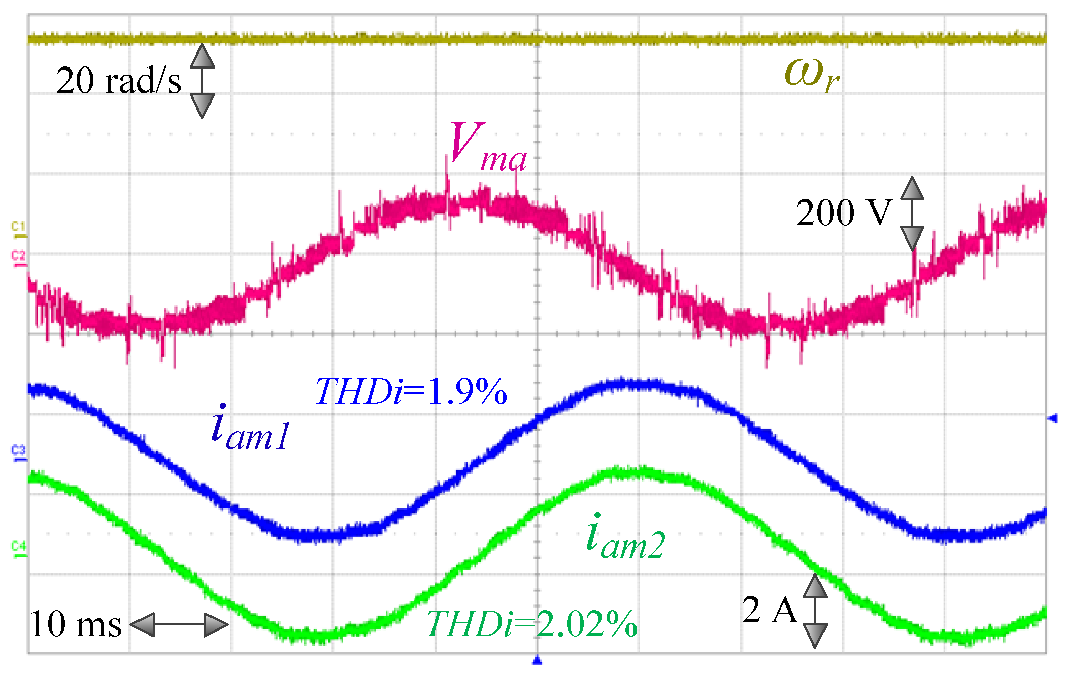
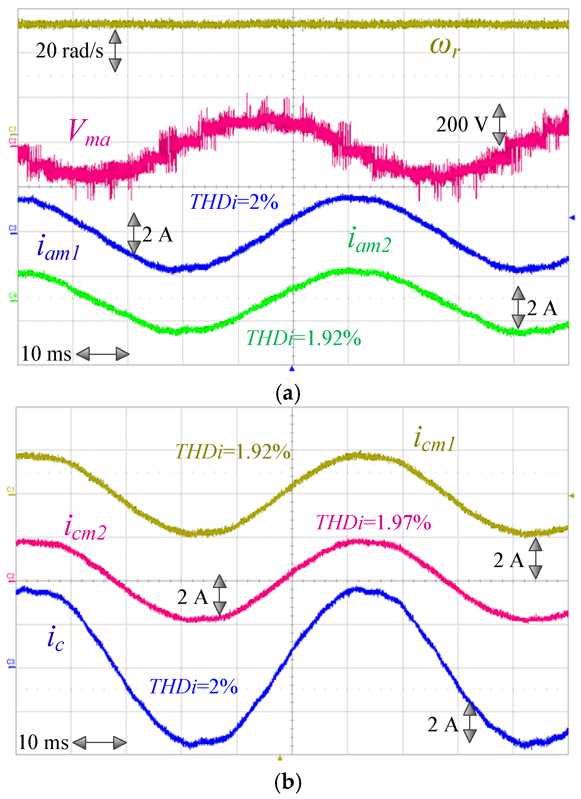
A comparison between the 3LI+TLI and 5LI+TLI MMSC configurations is provided in Figure 15. A steady state test (ωr1 = ωr2 = 50 rad/s) performed using the MMMC 5LI+TLI5 system is displayed in Figure 16. The c phase current of the TLI is higher than the currents of the other four phases, as it is given by the combination of the c phase currents of both motors.
Speed reversals from ωr = −40 rad/s to ωr = 40 rad/s accomplished by the 5LI+TLI MMSC and the 5LI+TLI5 MMMC prototypes, are shown in Figure 17. The drives feature a good dynamic response and an effective floating capacitor voltage control. The torque load was evenly shared between the two motors.
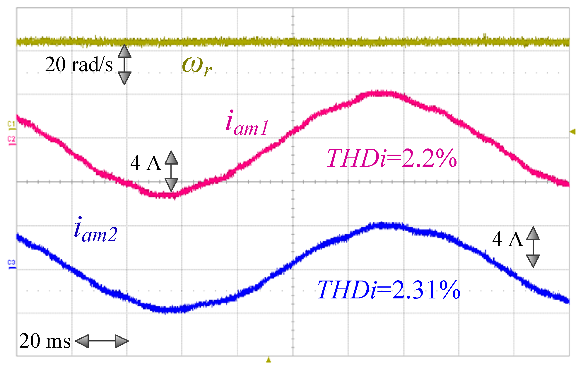
In order to assess the capability of the 5LI+TLI5 configuration to individually control the torque produced by the two motors, the previous test was repeated with uneven loading on the two machines. As shown in Figure 18, 70% of the load torque was produced by IM1 and 30% by IM2. Figure 19 shows the phase currents of IM1 and IM2 at the steady state for the MMMC. The steady state currents and dynamical torque, as well as, and speed response are quite satisfactory.
6. Conclusions
The paper has proposed a multi-level converter topology for multiple-motor drives based on a special open-end winding configuration. Applications of such a topology to multiple motors - single converter and multiple motor-multiple converter drives was also discussed. Specifically, two configurations, an MLI+TLI Multi Motor Single Converter system and an MLI+TLI5 Multi Motor Multi Converter system were presented and managed by purposely developed control strategies, combining a low switching frequency modulation on the MLI and high frequency PWM on the TLI. As shown in the paper, in both cases the proposed configurations produced much lower stator current distortion when compared to conventional multi-motor drives equipped with MLI switching at the fundamental frequency. Further, they generated lower power losses when compared to multi motor drives equipped with PWM operated MLI. Although the paper considers only multi motor systems comprising two identical induction machines, the proposed approach can be generalized for systems with an arbitrary amount of motors; it can also be exploited for multi motor systems using synchronous machines, and even for multi motor systems using a mix of machines of different sizes.
Author Contributions
Conceptualization, S.F., A.T., S.D.C., and G.S. (Giuseppe Scarcella); methodology, S.F., A.T., and G.S. (Giacomo Scelba); software, S.F., G.S. (Giacomo Scelba) and T.S.; validation, S.F., G.S. (Giacomo Scelba) and T.S.; supervision, A.T., G.S. (Giacomo Scelba) and G.S. (Giuseppe Scarcella).
Funding
This research received no external funding.
Conflicts of Interest
The authors declare no conflict of interest.
Nomenclature
| MMD | Multiple Motor Drive |
| MMSC | Multiple Motors fed by a Single Converter |
| MMMC | Multiple Motors fed by Multiple Converters |
| IFOC | Indirect Field Oriented Control |
| TLI | Two-Level Inverter |
| 3LI | Three-Level inverter |
| TLI5 | Five-leg two level inverter |
| 3LI+TLI | OW configuration including 3LI and TLI |
| 3LI+TLI5 | OW configuration including 3LI and TLI5 |
| 5LI+TLI | OW configuration including 5LI and TLI |
| 5LI+TLI5 | OW configuration including 5LI and TLI5 |
| THD | Total Harmonic Distortion |
| n | MLI voltage levels |
| VMLI_stepi | i-phase MLI output voltage with respect to n′ |
| VTLIi | i-phase TLI output voltage with respect to n″ |
| Vmi | i-phase motor voltage |
| VDC′ | MLI DC Bus voltage |
| VDC″ | TLI DC Bus voltage |
| Vmpk | Peak motor voltage |
| iabc1 | abc axes IM1 phase currents |
| iabc2 | abc axes IM2 phase currents |
| Eqd | qd axes motor back EMF |
| iqd1 | qd axes IM1 phase currents |
| iqd2 | qd axes IM1 phase currents |
| VqdMLI | qd axes MLI output voltage |
| Rs, Rr | Stator and rotor resistance |
| Rfe | Iron resistance |
| Ls, Lr | Stator and rotor inductances |
| Lm | Magnetizing inductance |
| ωλre | Rotor flux angular frequency |
| KV | Voltage ratio VDC″/VDC′ |
| Kp | Vmpk/(VDC′ *THDV) |
| ωr | Mechanical Rotor speed |
| ωre | Electrical Rotor speed |
| θλr1, θλr2 | Rotor flux angular positions of IM1 and IM2 |
| θr | Rotor angular positions of IM1 and IM2 |
| Te1n, Te2n | Rated torques of IM1 and IM2 |
| J | Total inertia of motor and load |
| pp | pole pairs |
| Vceo | Collector to Emitter Saturation Voltage |
| ton | Current Turn-On Delay Time |
| toff | Current Turn-Off Delay Time |
| VCES | Collector to Emitter Breakdown Voltage |
| IC | Collector current |
| VDSS | Drain-to-Source Breakdown Voltage |
| IDSS | Drain-to-Source Leakage Current |
| RDS(on) | Static Drain-to-Source On-Resistance |
| Piron | Motor iron losses |
| Pjoule | Motor joule losses |
| PCMLI | MLI conduction losses |
| PswMLI | MLI switching losses |
| PCTLI | TLI conduction losses |
| PswTLI | TLI switching losses |
| δ | Duty cycle of the 3LI |
| fswMLI | Switching frequency of the 3LI |
| fswTLI | Switching frequency of the TLI |
References
- Levi, E.; Jones, M.; Vukosavic, S.N.; Toliyat, H.A. A novel concept of a multiphase, multimotor vector controlled drive system supplied from a single voltage source inverter. IEEE Trans. Power Electron. 2004, 19, 320–335. [Google Scholar] [CrossRef]
- Jeftenic, B.; Bebic, M.; Statkic, S. Controlled multi-motor drives. In Proceedings of the International Symposium on Power Electronics, Electrical Drives, Automation and Motion SPEEDAM, Taormina, Italy, 23–26 May 2006; pp. 1392–1398. [Google Scholar]
- Iyer, J.; Tabarraee, K.; Chiniforoosh, S.; Jatskevich, J. An improved V/F control scheme for symmetric load sharing of multi-machine induction motor drives. In Proceedings of the Canadian Conference on Electrical and Computer Engineering (CCECE), Niagara Falls, ON, Canada, 8–11 May 2011; pp. 1487–1490. [Google Scholar]
- Pulvirenti, M.; Scarcella, G.; Scelba, G.; Cacciato, M.; Testa, A. FaultTolerant AC Multidrive System. IEEE J. Emerg. Sel. Top. Power Electron. 2014, 2, 224–235. [Google Scholar] [CrossRef]
- Scelba, G.; Scarcella, G.; Pulvirenti, M.; Cacciato, M.; Testa, A.; de Caro, S.; Scimone, T. Current-Sharing Strategies for Fault-Tolerant AC Multidives. IEEE Trans. Ind. Appl. 2015, 51, 3943–3953. [Google Scholar] [CrossRef]
- Slutej, A.; Kolonic, F.; Jakopovic, Z. The new crane motion control concept with integrated drive controller for engineered crane application. In Proceedings of the IEEE International Symposium on Industrial Electronics, ISIE, Bled, Slovenia, 12–16 July 1999; pp. 1458–1461. [Google Scholar]
- Mitrovic, N.; Petronijevic, M.; Kostic, V.; Jeftenic, B. Electrical Drives for Crane Application, Mechanical Engineering; Gokcek, M., Ed.; InTech: London, UK, 2012; ISBN 978-953-51-0505-3. [Google Scholar]
- Foti, S.; Testa, A.; de Caro, S.; Scimone, T.; Pulvirenti, M. Sensorless field oriented control of multiple-motors fed by multiple-converters systems. In Proceedings of the IEEE International Symposium on Sensorless Control for Electrical Drives (SLED), Catania, Italy, 18–19 September 2017; pp. 237–242. [Google Scholar]
- Matsumoto, Y.; Ozaki, S.; Kawamura, A. A novel vector control of single-inverter multiple-induction-motors drives for Shinkansen traction system. In Proceedings of the 16th Annual Applied Power Electronics Conference and Exposition, (APEC 2001), Anaheim, CA, USA, 4–8 March 2001; pp. 608–614. [Google Scholar]
- Peña-Eguiluz, R.; Pietrzak-David, M.; DeFornel, B. Comparison of several control strategies for parallel connected dual induction motors. In Proceedings of the VIII IEEE International Power Electronics Congress, 2002. Technical Proceedings. CIEP 2002, Guadalajara, Mexico, 24–24 October 2002. [Google Scholar]
- Mabrouk, W.B.; Belhadj, J.; Pietrzak-David, M. Synthesis and Analysis of one Bogie Induction Railway Traction System. In Proceedings of the on 13th European Conference on Power Electronics and Applications, Barcelona, Spain, 8–10 September 2009; pp. 1–9. [Google Scholar]
- Achour, T.; Pietrzak-David, M. Service Continuity of an IM Distributed Railway Traction with a Speed Sensor Fault. In Proceedings of the 14th European Conference on Power Electronics and Applications, Birmingham, UK, 30 August–1 September 2011; pp. 1–8. [Google Scholar]
- Cui, S.; Han, S.; Chan, C. Overview of multi-machine drive systems for electric and hybrid electric vehicles. In Proceedings of the IEEE Conference and Expo Transportation Electrification Asia-Pacific (ITEC Asia-Pacific), Beijing, China, 31 August–3 September 2014; pp. 1–6. [Google Scholar]
- Arnet, B.; Jufer, M. Torque control on electric vehicles with separate wheel drives. In Proceedings of the EPE Conference, Trondheim, Norway, 8–10 September 1997; pp. 659–664. [Google Scholar]
- Du, Z.; Tolbert, L.M.; Chiasson, J.N. Active harmonic elimination for multilevel converters. IEEE Trans. Power Electron. 2006, 21, 459–469. [Google Scholar]
- Tolbert, L.M.; Chiasson, J.N.; Du, Z.; McKenzie, K.J. Elimination of Harmonics in a Multilevel Converter with Non equal DC Sources. IEEE Trans. Ind. Appl. 2005, 41, 75–82. [Google Scholar] [CrossRef]
- Fong, Y.C.; Cheng, K.W.E. An adaptive modulation scheme for fundamental frequency switched multilevel inverter with unbalanced and varying voltage sources. In Proceedings of the Power Electronics Systems and Applications (PESA), Hong Kong, China, 15–17 December 2016; pp. 1–6. [Google Scholar]
- Edpuganti, A.; Rathore, A.K. Fundamental Switching Frequency Optimal Pulsewidth Modulation of Medium-Voltage Cascaded Seven-Level Inverter. IEEE Trans. Ind. Appl. 2015, 51, 3485–3492. [Google Scholar] [CrossRef]
- Corzine, K.A.; Sudhoff, S.D.; Whitcomb, C.A. Performance characteristics of a cascaded two-level converter. IEEE Trans. Energy Convers. 1999, 14, 433–439. [Google Scholar] [CrossRef]
- Li, L.; Czarkowski, D.; Liu, Y.; Pillay, P. Multi-level selective harmonic elimination PWM technique in serie-connected voltage inverters. IEEE Trans. Ind. Appl. 2000, 36, 160–170. [Google Scholar] [CrossRef]
- Napoles, J.; Leon, J.I.; Portillo, R.; Franquelo, L.G.; Aguirre, M.A. Selective Harmonic Mitigation Technique for High Power Converters. IEEE Trans. Ind. Electron. 2009, 57, 2197–2206. [Google Scholar] [CrossRef]
- Haitham, A.R.; Holtz, J.; Rodriguez, J.; Baoming, G. Medium Voltage Multilevel Converters-State of the Art, Challenges, and Requirements in Industrial Applications. IEEE Trans. Ind. Electron. 2010, 57, 2581–2596. [Google Scholar]
- Lai, J.-S.; Peng, F.Z. Multi-level converters-A new breed of power converters. IEEE Trans. Ind. Appl. 1996, 32, 509–517. [Google Scholar]
- Davari, P.; Yang, Y.; Zare, F.; Blaabjerg, F. A novel harmonic elimination approach in three-phase multi-motor drives. In Proceedings of the IEEE Energy Conversion Congress and Exposition (ECCE), Montreal, QC, Canada, 20–24 September 2015; pp. 7001–7008. [Google Scholar]
- Sivakumar, K.; Das, A.; Ramchand, R.; Patel, C. A Hybrid Multilevel Inverter Topology for an Open-End Winding Induction Motor Drive Using Two-Level Inverters in Series with a Capacitor-Fed H-Bridge Cell. IEEE Trans. Ind. Electron. 2010, 57, 3707–3714. [Google Scholar] [CrossRef]
- Boller, T.; Holtz, J.; Rathore, A.K. Optimal pulse width modulation of a dual 3LI system operated from a single dc link. IEEE Trans. Ind. Appl. 2012, 48, 1610–1615. [Google Scholar] [CrossRef]
- Mondal, G.; Sivakumar, K.; Ramchand, R.; Gopakumar, K.; Levi, E. A Dual Seven-Level Inverter Supply for an Open-End Winding Induction Motor Drive. IEEE Trans. Ind. Electron. 2008, 56, 1665–1673. [Google Scholar] [CrossRef]
- Somasekhar, T.; Gopakumar, K.; Bajiu, M.R.; Mohapatra, K.K.; Umanand, L. A multilevel inverter system for an inductor motor with open-end windings. IEEE Trans. Ind. Electron. 2005, 52, 824–836. [Google Scholar] [CrossRef]
- Edpuganti, A.; Rathore, A.K. New Optimal Pulse Width Modulation for Single DC-Link Dual-Inverter Fed Open-End Stator Winding Induction Motor Drive. IEEE Trans. Power Electron. 2014, 30, 4386–4393. [Google Scholar]
- Foti, S.; Testa, A.; Scelba, G.; de Caro, S.; Cacciato, M.; Scarcella, G.; Bazzano, D.; Scimone, T. A new approach to improve the current harmonic content on open-end winding AC motors supplied by multi-level inverters. In Proceedings of the IEEE Energy Conversion Congress and Exposition (ECCE), Montreal, QC, Canada, 20–24 September 2015; pp. 4040–4047. [Google Scholar]
- Foti, S.; Testa, A.; Scelba, G.; de Caro, S.; Cacciato, M.; Scarcella, G.; Scimone, T. An Open End Winding Motor Approach to mitigate the phase voltage distortion on Multi-Level Inverters. IEEE Trans. Power Electron. 2018, 33, 2404–2416. [Google Scholar] [CrossRef]
- De Caro, S.; Foti, S.; Scimone, T.; Testa, A.; Cacciato, M.; Scarcella, G.; Scelba, G. THD and efficiency improvement in multi-level inverters through an open end winding configuration. In Proceedings of the 2016 IEEE Energy Conversion Congress and Exposition (ECCE), Milwaukee, WI, USA, 18–22 September 2016; pp. 1–7. [Google Scholar]
- Foti, S.; Scelba, G.; Testa, A.; Sciacca, A. An Averaged-Value Model of an Asymmetrical Hybrid Multi-Level Rectifier. Energies 2019, 12, 589. [Google Scholar] [CrossRef]
- Foti, S.; de Caro, S.; Scelba, G.; Scimone, T.; Testa, A.; Cacciato, M.; Scarcella, G. An Optimal Current Control Strategy for Asymmetrical Hybrid Multilevel Inverters. IEEE Trans. Ind. Appl. 2018, 54, 4425–4436. [Google Scholar] [CrossRef]
- De Caro, S.; Foti, S.; Scimone, T.; Testa, A.; Cacciato, M.; Pulvirenti, M.; Russo, S. Over-voltage mitigation on SiC based motor drives through an open end winding configuration. In Proceedings of the 2017 IEEE Energy Conversion Congress and Exposition (ECCE), Cincinnati, OH, USA, 1–5 October 2017; pp. 4332–4337. [Google Scholar]
- Foti, S.; Testa, A.; Scelba, G.; Cacciato, M.; de Caro, G.S.S.; Scimone, T. Overvoltage mitigation in open-end winding AC motor drives. In Proceedings of the 2015 IEEE ICRERA, Palermo, Italy, 22–25 November 2015; pp. 235–238. [Google Scholar]
- Scelba, G.; Scarcella, G.; Foti, S.; Testa, A.; de Caro, S.; Scimone, T. An Open-end Winding approach to the design of multi-level multi-motor drives. In Proceedings of the IECON 2016—42nd Annual Conference of the IEEE Industrial Electronics Society, Florence, Italy, 23–26 October 2016; pp. 5026–5032. [Google Scholar]
- Haque, R.U.; Toulabi, M.S.; Knight, A.M.; Salmon, J. Wide speed range operation of PMSM using an open winding and a dual inverter drive with a floating bridge. In Proceedings of the IEEE Energy Conversion Congress and Exposition (ECCE), Denver, CO, USA, 15–19 September 2013; pp. 3784–3791. [Google Scholar]
- Cacciato, M.; Consoli, A.; Finocchiaro, L.; Testa, A. High frequency modeling of bearing currents and shaft voltage on electrical motors. In Proceedings of the Eighth International Conference on Electrical Machines and Systems, Nanjing, China, 27–29 September 2005; pp. 2065–2070. [Google Scholar]
- Cacciato, M.; Cavallaro, C.; Scarcella, G.; Testa, A. Effects of connection cable length on conducted EMI in electric drives. In Proceedings of the IEEE International Electric Machines and Drives Conference, Seattle, WA, USA, 9–12 May 1999; pp. 428–430. [Google Scholar]
- Cacciato, M.; De Caro, S.; Scarcella, G.; Scelba, G.; Testa, A. Improved space-vector modulation technique for common mode currents reduction. IET Power Electron. 2013, 6, 1248–1256. [Google Scholar] [CrossRef]
- Foti, S.; Testa, A.; Scelba, G.; Sabatini, V.; Lidozzi, A.; Solero, L. Asymmetrical hybrid unidirectional T-type rectifier for high-speed gen-set applications. In Proceedings of the IEEE Energy Conversion Congress and Exposition (ECCE), Cincinnati, OH, USA, 1–5 October 2017; pp. 4887–4893. [Google Scholar]
- Scelba, G.; Scarcella, G.; Foti, S.; De Caro, S.; Testa, A. Self-sensing control of open-end winding PMSMs fed by an asymmetrical hybrid multilevel inverter. In Proceedings of the IEEE International Symposium on Sensorless Control for Electrical Drives (SLED), Catania, Italy, 18–19 September 2017; pp. 165–172. [Google Scholar]
- De Caro, S.; Foti, S.; Scelba, G.; Scimone, T.; Testa, A. A six-level asymmetrical Hybrid Photovoltaic Inverter with inner MPPT capability. In Proceedings of the 6th International Conference on Clean Electrical Power (ICCEP), Santa Margherita Ligure, Italy, 27–29 June 2017; pp. 631–635. [Google Scholar]
- Dujic, D.; Jones, M.; Vukosavic, S.N.; Levi, E. A general PWM method for a (2n+1)-leg inverter supplying n three-phase machines. IEEE Trans. Ind. Electron. 2009, 56, 4107–4118. [Google Scholar] [CrossRef]
- Rifkin, S. Adjustable-Voltage Hoist Drives for Cranes. IEEE Electr. Eng. 1956, 75, 620–623. [Google Scholar] [CrossRef]
- Myles, A.H.; Davies, M.C.; Srnka, L.J. DC magnetic crane hoist control for AC powered cranes. Trans. Am. Inst. Electr. Eng. Part I Commun. Electron. 1960, 79, 207–211. [Google Scholar]
- Ruxi, W.; Yue, W.; Qiang, D.; Yanhui, H.; Zhaoan, W. Study of control methodology for single inverter parallel connected dual induction motors based on the dynamic model. In Proceedings of the 2006 37th IEEE Power Electronics Specialists Conference, Jeju, Korea, 18–22 June 2017; pp. 1–7. [Google Scholar]
- Matsuse, K.; Kouno, Y.; Kawai, H.; Yokomizo, S. A speed-sensorless vector control method of parallel-connected dual induction motor fed by a single inverter. IEEE Trans. Ind. Appl. 2002, 38, 1566–1571. [Google Scholar] [CrossRef]
- Kelecy, P.M.; Lorenz, R.D. Control methodology for single inverter, parallel connected dual induction motor drives for electric vehicles. In Proceedings of the Power Electronics Specialists Conference, PESC ’94 Record, 25th Annual IEEE, Taipei, Taiwan, 20–25 June 1994; Volume 2, pp. 987–991. [Google Scholar]
- Dixit, A.; Mishra, N.; Sinha, S.K.; Singh, P. A review on different PWM techniques for five leg voltage source inverter. In Proceedings of the IEEE-International Conference On Advances In Engineering, Science And Management (ICAESM), Nagapattinam, Tamil Nadu, India, 30–31 March 2012; pp. 421–428. [Google Scholar]
- Tabbache, A.; Rebaa, K.; Marouani, K.; Benbouzid, M.E.H.; Kheloui, A. Independent control of two induction motors fed by a five legs PWM inverter for electric vehicles. In Proceedings of the 2013 4th International Conference on Power Engineering, Energy and Electrical Drives, Istanbul, Turkey, 13–17 May 2013; pp. 629–634. [Google Scholar]
- Pradabane, S. A New SVPWM for Dual-Inverter fed Three-level Induction Motor Drive. In Proceedings of the 2013 4th International Conference on Green Computing, Communication and Conservation of Energy, Chennai, India, 12–14 December 2014; pp. 514–518. [Google Scholar]
Figure 1.
Common speed reference control of a Multiple Motors fed by Multiple Converters (MMMC) system.
Figure 1.
Common speed reference control of a Multiple Motors fed by Multiple Converters (MMMC) system.

Figure 2.
Proposed Open-end Winding (OW) Multi-level inverter (MLI) + Two Level Inverter (TLI) Multiple Motors Fed by a Single Multi-level Converter (MMSC) configuration.
Figure 2.
Proposed Open-end Winding (OW) Multi-level inverter (MLI) + Two Level Inverter (TLI) Multiple Motors Fed by a Single Multi-level Converter (MMSC) configuration.
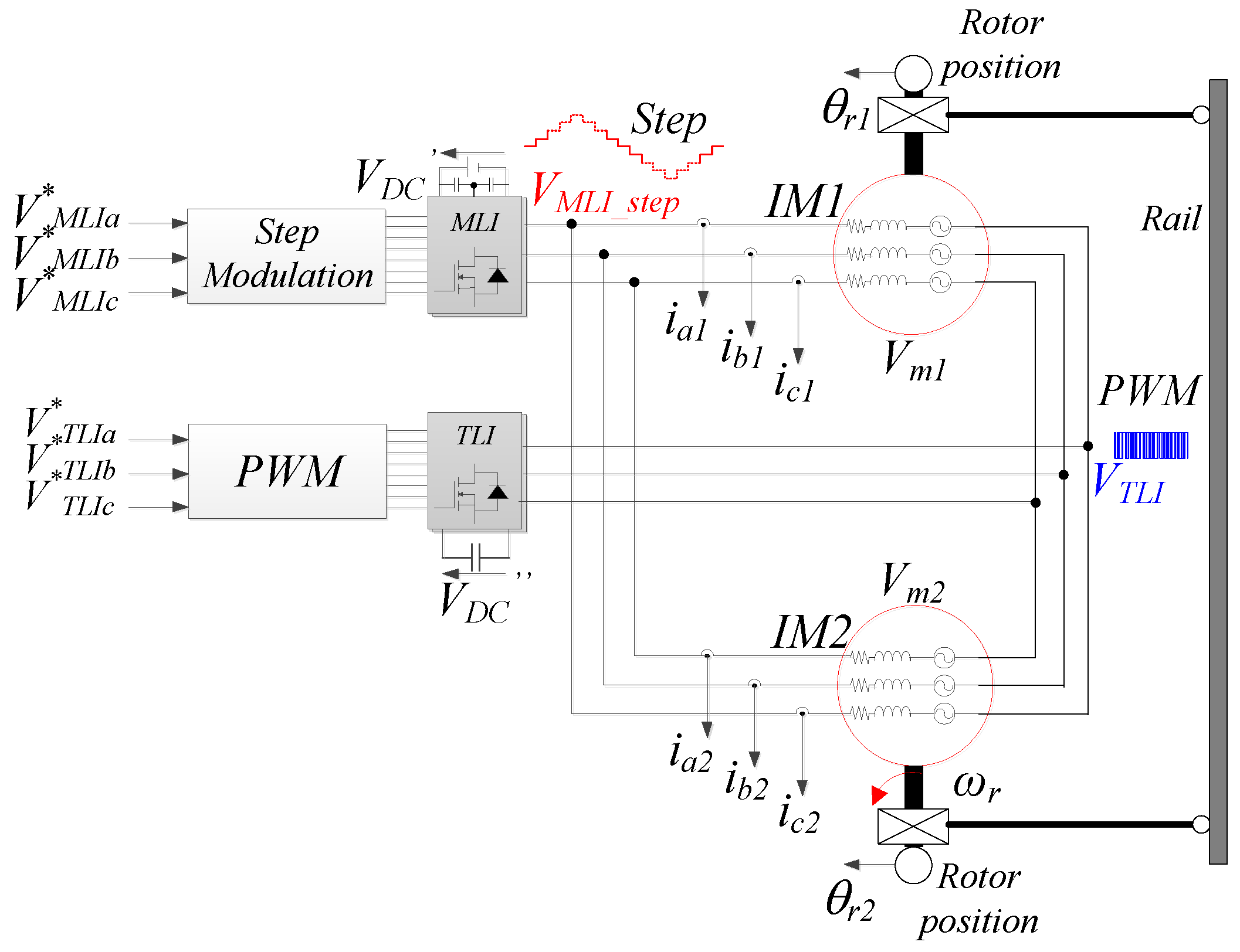
Figure 3.
Block diagram of the OW MLI+TLI MMSC voltage control.

Figure 4.
VMLI_stepi, V*MLIi and V*TLIi waveforms.

Figure 5.
Phase voltage space phasor diagram (a) VDC″/VDC′ = 1/8; (b) VDC″/VDC′ = 1/4; (c) VDC″/VDC′ = 1/2; (d) VDC″/VDC′ = 1.
Figure 5.
Phase voltage space phasor diagram (a) VDC″/VDC′ = 1/8; (b) VDC″/VDC′ = 1/4; (c) VDC″/VDC′ = 1/2; (d) VDC″/VDC′ = 1.

Figure 6.
MLI+TLI MMSC control strategy.

Figure 7.
MLI+TLI5 OW MMMC configuration.

Figure 8.
MLI+TLI5 OW MMMC control structure.
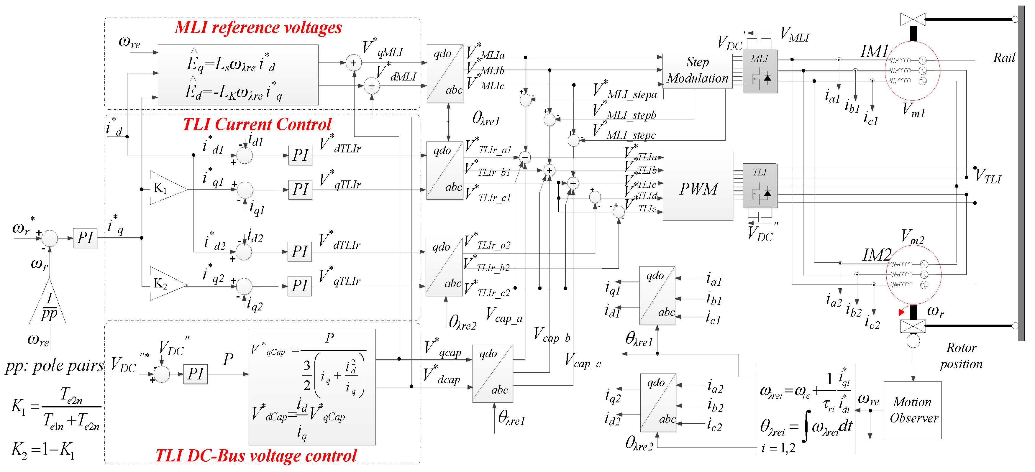
Figure 9.
Motor iron losses Piron, motor joule losses Pjoule, MLI conduction losses PCMLI, MLI switching losses PswMLI, TLI conduction losses PCTLI and TLI switching losses PswTLI: (a) 3LI step modulated; (b) 3LI PWM modulated; (c) 3LI+TLI configuration.
Figure 9.
Motor iron losses Piron, motor joule losses Pjoule, MLI conduction losses PCMLI, MLI switching losses PswMLI, TLI conduction losses PCTLI and TLI switching losses PswTLI: (a) 3LI step modulated; (b) 3LI PWM modulated; (c) 3LI+TLI configuration.
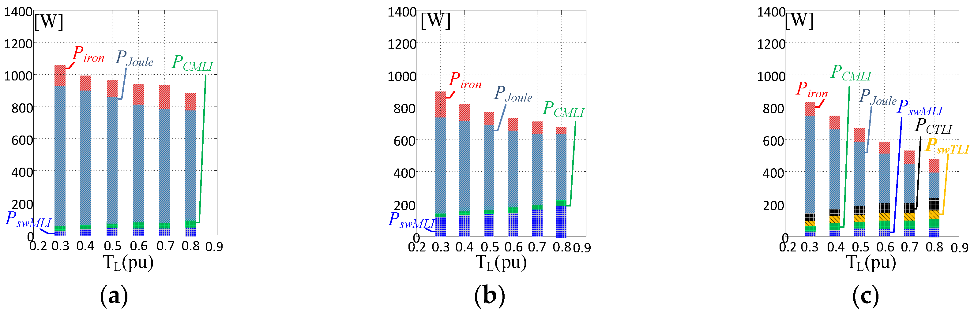
Figure 10.
Total efficiency of the MMSC: (a) 3LI step operated; (b) 3LI PWM operated; (c) 3LI+TLI configuration.
Figure 10.
Total efficiency of the MMSC: (a) 3LI step operated; (b) 3LI PWM operated; (c) 3LI+TLI configuration.
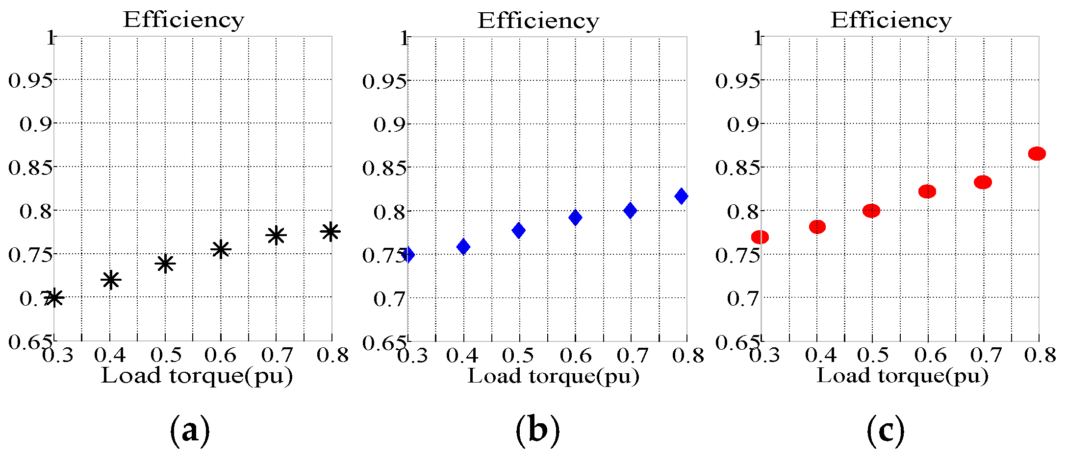
Figure 11.
Total efficiency of the system: (a) 3LI PWM operated; (b) 3LI+TLI5 configuration.
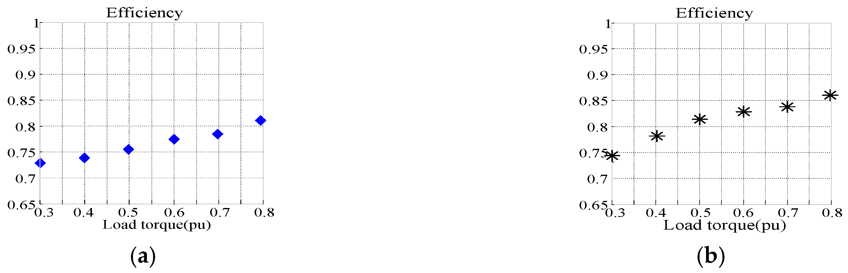
Figure 12.
Experimental setup of OW MMSC.
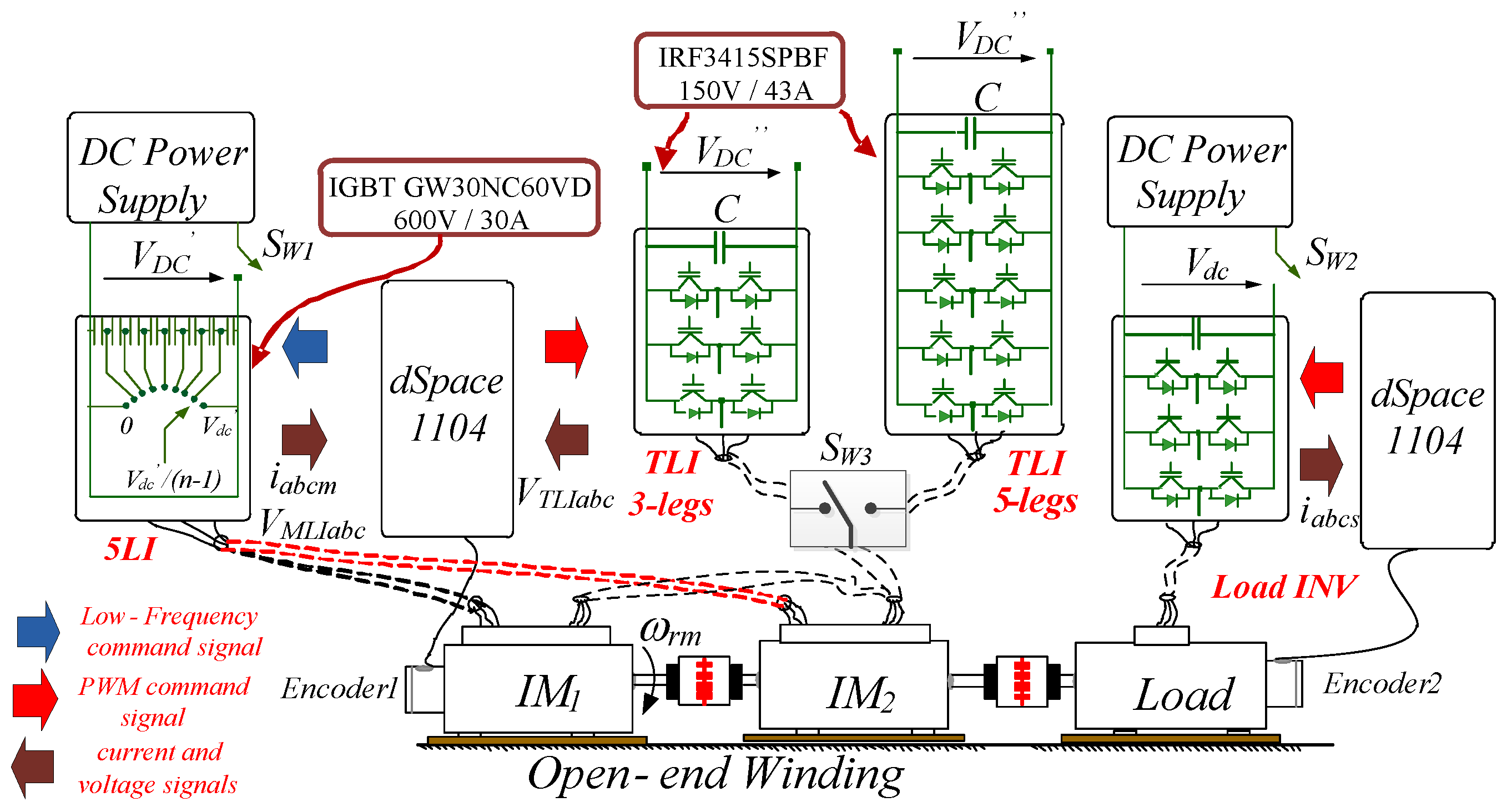
Figure 13.
Conventional configuration, both motors are wye-connected and fed by a step operated 5MLI: steady state test at ωr = 50 rad/s and with no load. Motor speed ωr, a-phase motor Vma, motor currents iam1 and iam2.
Figure 13.
Conventional configuration, both motors are wye-connected and fed by a step operated 5MLI: steady state test at ωr = 50 rad/s and with no load. Motor speed ωr, a-phase motor Vma, motor currents iam1 and iam2.
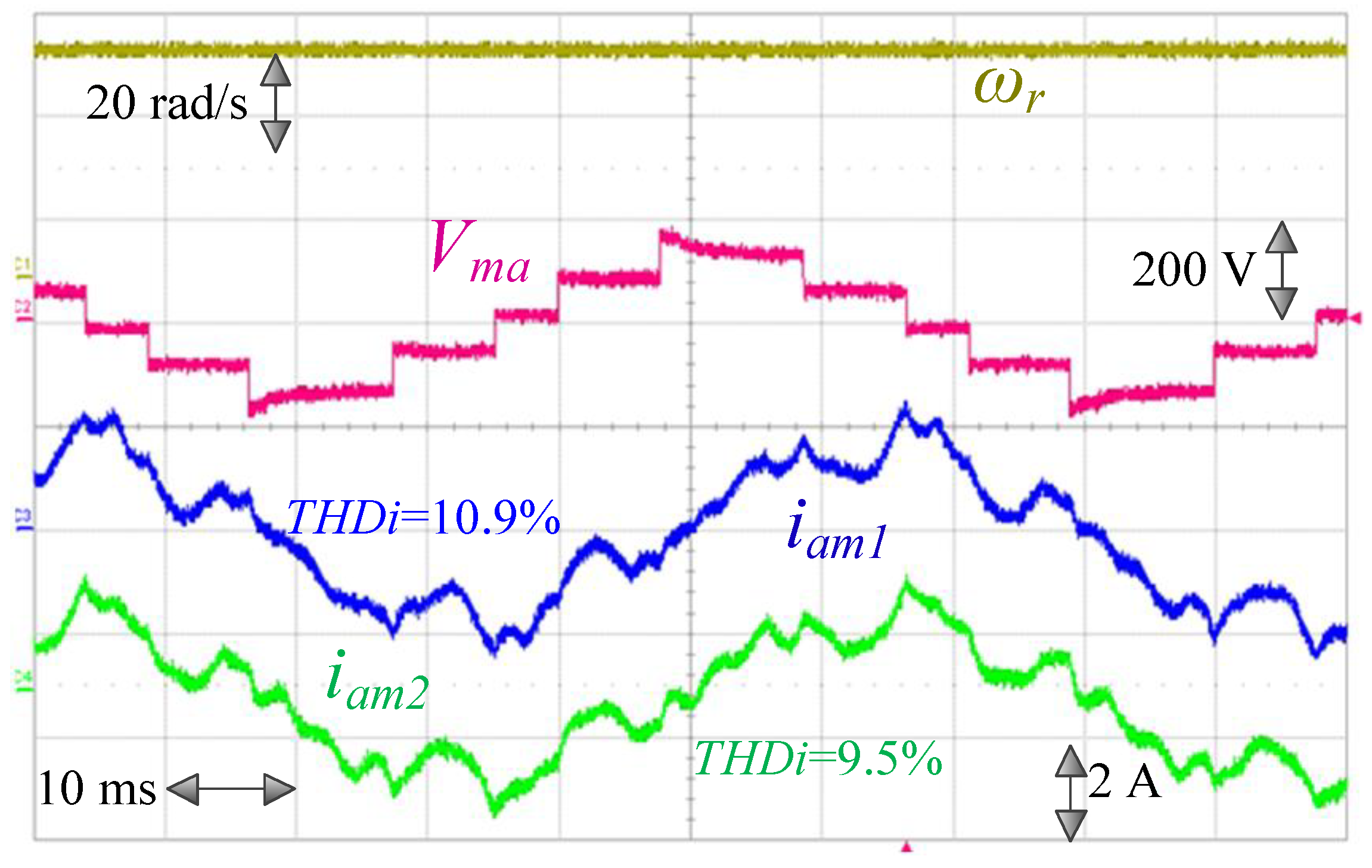
Figure 14.
5LI+TLI MMSC: steady state test at ωr = 50 rad/s. Motor speed ωr, a-phase motor Vma, motor currents iam1 and iam2.
Figure 14.
5LI+TLI MMSC: steady state test at ωr = 50 rad/s. Motor speed ωr, a-phase motor Vma, motor currents iam1 and iam2.

Figure 15.
(a) MMSC (3LI+TLI); (b) MMSC (5LI+TLI). Steady state test, stator voltage Vma, stattor current iam1, TLI output voltage VTLIa and TLI voltage reference V*TLIa.
Figure 15.
(a) MMSC (3LI+TLI); (b) MMSC (5LI+TLI). Steady state test, stator voltage Vma, stattor current iam1, TLI output voltage VTLIa and TLI voltage reference V*TLIa.
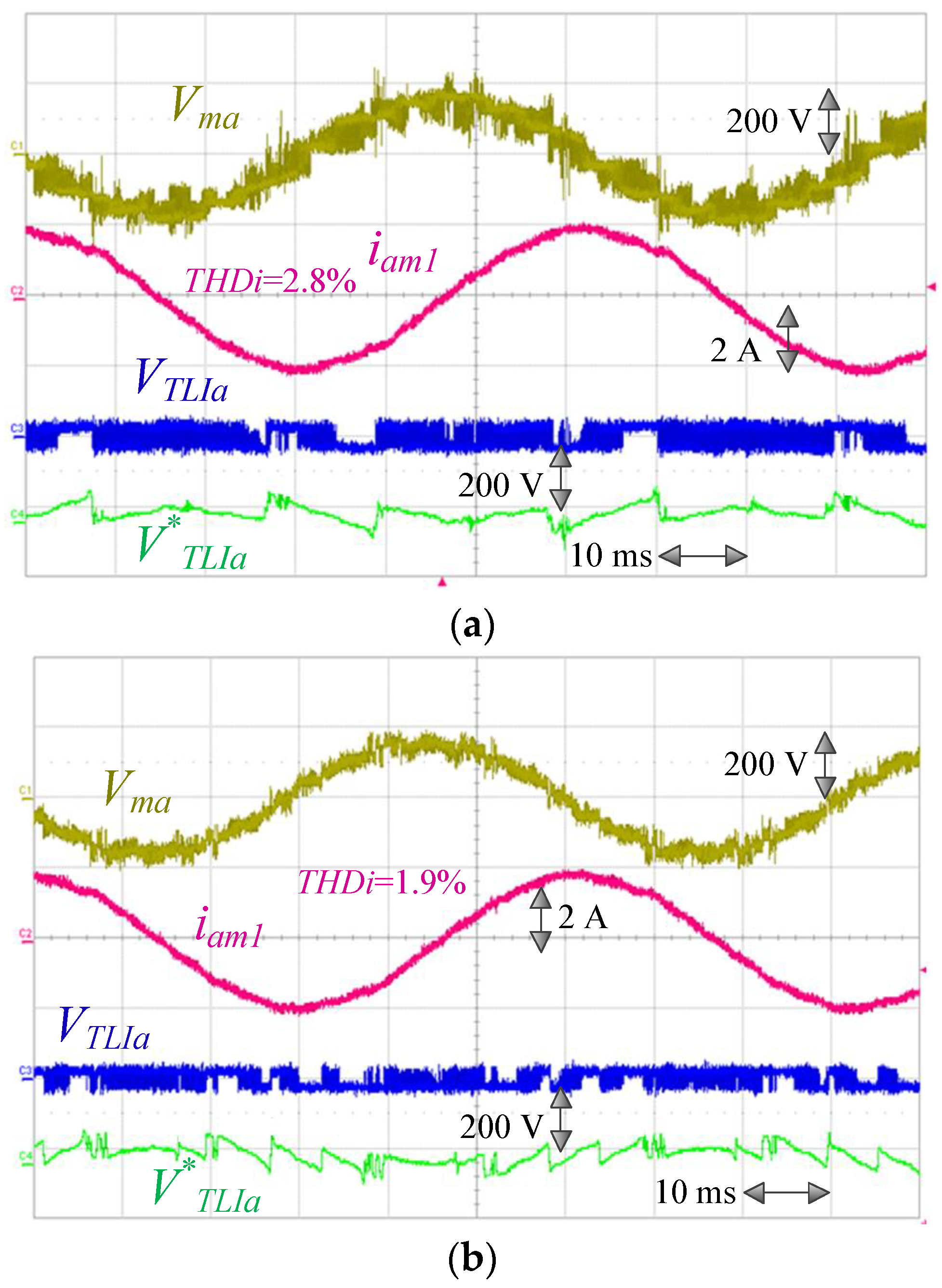
Figure 16.
5LI+TLI5 MMMC, Steady state test at ωr = 50 rad/s. (a) Motor speed ωr, a-phase motor Vma, motor currents iam1 and iam2; (b) motor currents iam1 and iam2 and common-leg c-phase current ic.
Figure 16.
5LI+TLI5 MMMC, Steady state test at ωr = 50 rad/s. (a) Motor speed ωr, a-phase motor Vma, motor currents iam1 and iam2; (b) motor currents iam1 and iam2 and common-leg c-phase current ic.

Figure 17.
(a) 5LI+TLI5 MMSC; (b) 5LI+TLI5 OW MMMC: speed reversal with idref = 2 A. Motor speed ωr, q-axes currents components iq1 and iq2 and TLI DC Bus voltage VDC″.
Figure 17.
(a) 5LI+TLI5 MMSC; (b) 5LI+TLI5 OW MMMC: speed reversal with idref = 2 A. Motor speed ωr, q-axes currents components iq1 and iq2 and TLI DC Bus voltage VDC″.

Figure 18.
MMMC 5LI+TLI5: speed reversal with. idref = 2 A, iq1 = 0.7 iq and iq2 = 0.3 iq. Motor speed ωr, q-axes currents components iq1 and iq2 and TLI DC Bus voltage VDC″.
Figure 18.
MMMC 5LI+TLI5: speed reversal with. idref = 2 A, iq1 = 0.7 iq and iq2 = 0.3 iq. Motor speed ωr, q-axes currents components iq1 and iq2 and TLI DC Bus voltage VDC″.
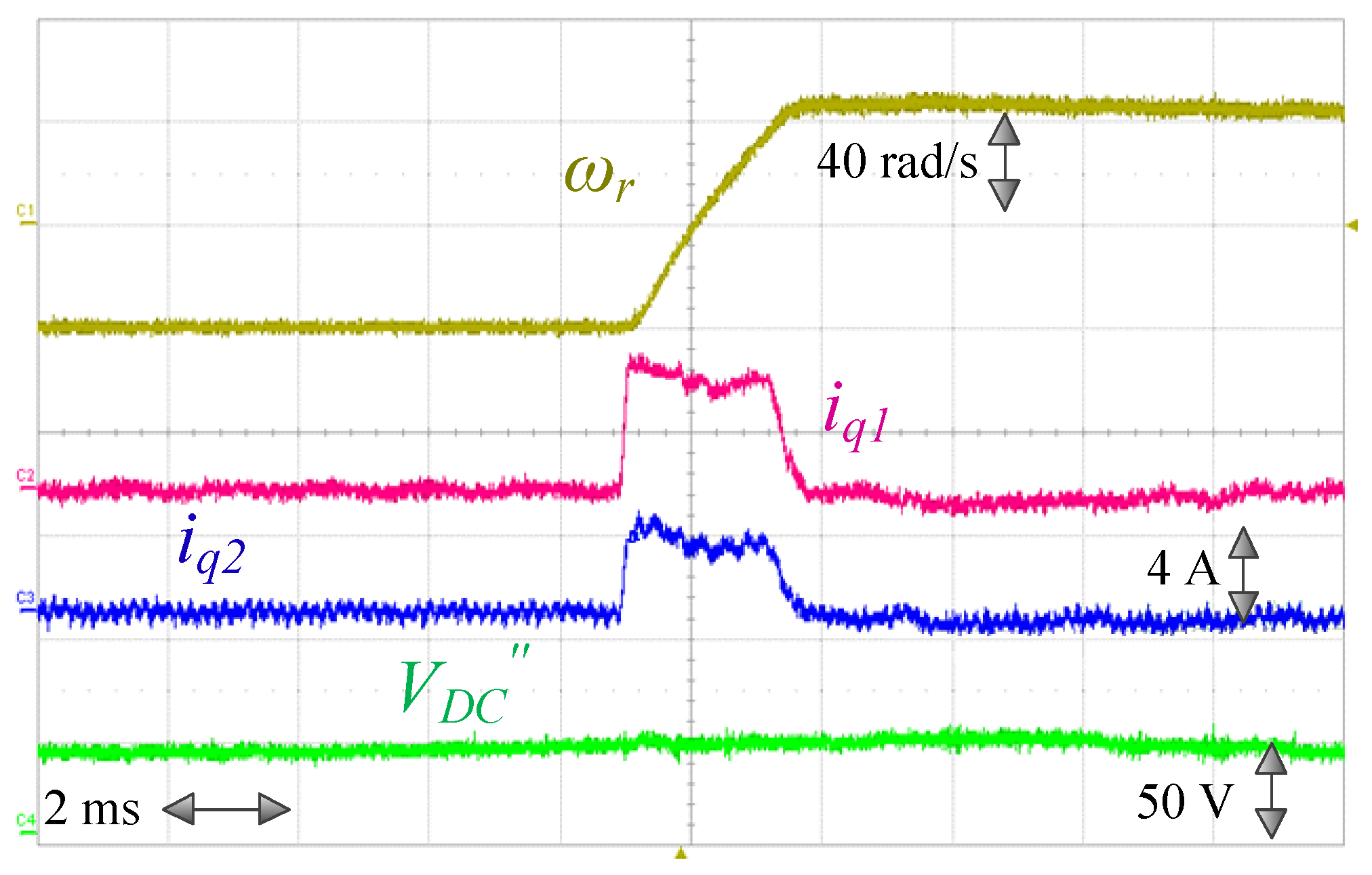
Figure 19.
MMMC 5LI+TLI5: Steady state at ωr = 50 rad/s and 50% of rated load, speed ωr, currents iam1 and iam2.
Figure 19.
MMMC 5LI+TLI5: Steady state at ωr = 50 rad/s and 50% of rated load, speed ωr, currents iam1 and iam2.

Table 1.
Switching states and voltage vector of Three Level Inverter (3LI).
| Vector | Magnitude | Switching State |
|---|---|---|
| Zero vector | 0 | PPP, OOO, NNN |
| Small vector | 1/3 VDC′ | POO, PPO, OPO, OPP, POP, OOPONN, OON, NON, NOO, ONO, NNO |
| Medium vector | /3 VDC′ | PON, OPN, NPO, NOP, ONP, PNO |
| Large vector | 2/3 VDC′ | PNN, PPN, NPN, NPP, NNP, PNP |
Table 2.
Power converter specifications vs. KV for Three Level Inverter + Two Level Inverter (3LI+TLI).
Table 2.
Power converter specifications vs. KV for Three Level Inverter + Two Level Inverter (3LI+TLI).
| KV | Number of Inverter States | Number of Voltage Vectors | Number of Voltage Levels |
|---|---|---|---|
| 1/8 | 216 | 152 | 8 |
| 1/4 | 216 | 91 | 6 |
| 1/2 | 216 | 37 | 4 |
| 1 | 216 | 61 | 5 |
Table 3.
Vmpk and THDv vs. KV (3LI+TLI).
| KV | Vmpk | THDV (%)\KP ωr/ωn = 0.1 | THDV (%)\KP ωr/ωn = 0.3 | THDV (%)\KP ωr/ωn = 0.7 | THDV (%)\KP ωr/ωn = 1 |
|---|---|---|---|---|---|
| 1/8 | 0.58 VDC′ | 51\1.14 | 45\1.29 | 30\1.93 | 19\3 |
| 1/4 | 0.72 VDC′ | 36\2 | 29\2.48 | 15\4.8 | 4.0\20.5 |
| 1/2 | 0.87 VDC′ | 10\8.7 | 8\10.88 | 7.1\12.2 | 3.5\21.7 |
| 1 | 1.15 VDC′ | 46\2.5 | 40\2.88 | 31\3.7 | 22.6\5.1 |
Table 4.
Technical specifications of the Induction Motors.
| Pn (HP) | Vn (V) | pp | Ls (mH) | Lr (H) | Lm (H) | Rs (Ω) | Rfe (Ω) | Rr (Ω) | J (Kg·m2) |
|---|---|---|---|---|---|---|---|---|---|
| 3 | 400 | 2 | 0.32 | 0.32 | 0.31 | 2.6 | 902 | 2.7 | 0.016 |
Table 5.
MLI IGBT Data.
| VCES (V) | IC (A) | Tj (°C) | Vceo (V) | ton (ns) | toff (ns) |
|---|---|---|---|---|---|
| 600 | 20 | 150 | 0.75 | 60 | 131 |
Table 6.
TLI MOSFET Data.
| VDSS (V) | IDSS (A) | Tj (°C) | RDS(on) (mΩ) | ton (ns) | toff (ns) |
|---|---|---|---|---|---|
| 150 | 20 | 175 | 32 | 8.9 | 17.2 |
© 2019 by the authors. Licensee MDPI, Basel, Switzerland. This article is an open access article distributed under the terms and conditions of the Creative Commons Attribution (CC BY) license (http://creativecommons.org/licenses/by/4.0/).
Share and Cite
MDPI and ACS Style
Foti, S.; Testa, A.; De Caro, S.; Scimone, T.; Scelba, G.; Scarcella, G. Multi-Level Open End Windings Multi-Motor Drives. Energies 2019, 12, 861. https://doi.org/10.3390/en12050861
AMA Style
Foti S, Testa A, De Caro S, Scimone T, Scelba G, Scarcella G. Multi-Level Open End Windings Multi-Motor Drives. Energies. 2019; 12(5):861. https://doi.org/10.3390/en12050861
Chicago/Turabian StyleFoti, Salvatore, Antonio Testa, Salvatore De Caro, Tommaso Scimone, Giacomo Scelba, and Giuseppe Scarcella. 2019. "Multi-Level Open End Windings Multi-Motor Drives" Energies 12, no. 5: 861. https://doi.org/10.3390/en12050861
Note that from the first issue of 2016, this journal uses article numbers instead of page numbers. See further details here.