Problems Related to Gasification of Biomass—Properties of Solid Pollutants in Raw Gas
by
Jan Najser
1, 
Petr Buryan
2,
Sergej Skoblia
2,
Jaroslav Frantik
1,
Jan Kielar
1 and
Vaclav Peer
1,* 1
ENET Centre, VSB-Technical University of Ostrava, 17. listopadu 15/2172, 70833 Ostrava-Poruba, Czech Republic
2
Department of Gaseous and Solid Fuels and Air Protection, UCT Prague, Technicka 5, 16628 Prague 6-Dejvice, Czech Republic
*
Author to whom correspondence should be addressed.
Energies 2019, 12(6), 963; https://doi.org/10.3390/en12060963
Submission received: 31 December 2018
/
Revised: 21 February 2019
/
Accepted: 8 March 2019
/
Published: 13 March 2019
(This article belongs to the Special Issue Selected Papers from PRES 2018: The 21st Conference on Process Integration, Modelling and Optimisation for Energy Saving and Pollution Reduction)
Abstract
:Nowadays, thermochemical biomass conversion appears to be a very promising way to process heat and steam generation, for use in a cogeneration unit engine, or for example in gas turbines producing electrical energy. The biggest problem regarding using the syngas in internal combustion engines, are pollutants, which have quite an inauspicious influence on their proper working. This article deals with the establishment of the distribution size of solid particles captured by the fiber filters in the syngas with a suitable cleaning design. Gas was produced in the fixed-bed “Imbert” type generator. Filter cake, which contained pollutants, was captured on a filter and then analyzed. Based on single total solid particles (TSP) components, we conclude that this includes its partial elimination.
1. Gasification of Biomass
In recent years, biomass, as a renewable source of energy, has attracted rising attention around the world [1].
The thermochemical transformation of biomass (pyrolysis, gasification) seems to be one of the most promising routes towards the utilization of renewable sources of energy to obtain energy. These renewable forms of energy present many ecological benefits. With respect to thermochemical conversion technologies, fixed-bed [2] or fluidised bed [3] gasification attracts the greatest attention because it offers higher process efficiency than combustion and pyrolysis.
The process of conversion of solid carbonaceous fuel to flammable gas by partial oxidation is known as gasification. The resultant gas, which is sometimes called process gas, is much more versatile in its use than the original solid biomass [4]. The great advantages are that the synthesis gas can be stored and transported, and its final use can be independent of the production process [5]. During final processing the synthesis gas can be combusted to produce process heat and steam or used in gas turbines for the production of electricity.
In terms of a gasification medium, the technology can be divided into gasification by air, oxygen, water vapors, CO2, or other various combinations [6].
2. Problems of Gasification Technologies and Their Solutions
Currently, during the development of new technologies for transforming the energy content of biomass as a renewable energy source to its more sophisticated form, attention is focused on the development of new technological equipment for more efficient gasification, or thermochemical conversion. In this technological segment, the majority of research work is aimed at the cleaning of raw generator gas, because tar and solid pollutants (SP) present in the raw gas are the main undesirable components in the gas, limiting its use in combustion motors or cogeneration unit turbines [7].
The increase in production efficiency sets ever growing demands for gas cleaning [8]. The benefits of gasification also include the possible reduction of emissions, emissions of compounds of Sulphur, chlorine, and nitrogen, but also persistent organic pollutants (POP), e.g., polychlorinated benzodioxines and benzodifuranes (PCDD, PCDF). Reduction of emissions is achieved by removing these compounds and their precursors directly from the produced gas prior to combustion. The volume of gas is smaller compared to the volume of produced flue gases; the concentration of pollutants is higher, and more efficient removal in smaller technological equipment is possible. Pollutants are present in a reduced form; their aggressiveness towards equipment is significantly lower.
2.1. Undesirable Substances
The choice of a suitable procedure for cleaning depends on the technology selected for its properties and content of undesirable components [9]. Undesirable components are formed from inorganic components of fuel or incomplete conversion of material. They cause abrasion, corrosion, formation of sediments, and degradation reactions, e.g., in catalyzers, or they represent ecological loads [8].
The volume of contaminating substances in the gas generated during gasification is directly dependent on the contamination of solid fuel. The volume of undesirable substances in biomass and the conversion process can be significant, e.g., N, P, K, Si, Ca, Mg, S, Na, Cl [6]. The main portion of heavy and alkali metals (potassium 80%) tend to stay in the solid phase during fuel conversion [10].
The following pollutants are formed during the gasification process:
- Solid pollutants (SP) are defined as substances in the resultant gas formed by unreacted biomass fraction and ash matter (inorganic substances). A certain proportion is also formed by soot, and its removal is problematic due to the presence of tar [11]. When the gas is cooled, there is a risk of more solid particles forming. Wet scrubbing, high-temperatures barrier filters [12], cyclones, and electrostatic separators are used for removal purposes [13].
- Tars can be defined as organic substances which are produced on the basis of thermal or partial oxidation of any organic material [14]. Generally it is presumed that tars are largely composed of polycyclic aromatic hydrocarbons (PAH). Tar substances can be classified as primary, secondary, or tertiary, according to the operating conditions under which they originated. Primary tars, which contain oxygen in substantial volumes, are formed by the decomposition of biomass building blocks. Secondary and tertiary tars are formed by the destruction of primary tar substances and the recombination of fragments [15]. During these processes, oxygen and particles of hydrogen are removed [16].
- Compounds containing nitrogen
- Alkaline compounds
- Sulphur
- Chlorine
2.2. Gas Utilization
Gas can be combusted in a burner, combustion engine, or gas turbine. If gas is combusted in a burner, only heat is generated. The dust is removed from gas in cyclones. During combustion in an engine or turbine, the benefit is electricity and waste heat. If the gas is a fuel for a combustion turbine, it must be de-dusted. Tars do not need to be removed because the temperature in the turbine chamber is way above the tar dew point. Tar removal is required when the gas is used in a combustion engine. The demands for gas quality are increasing from gas motors to fuel cells. Table 1 and Table 2 show the general requirements for gas quality for a gas turbine and for compression ignition and spark ignition engines. Table 3 shows the limits of pollutants for Molten Carbonate Fuel Cells (MCFC) operation.
2.3. SP Removal
To remove mechanical impurities and tar droplets originating from condensation, separators are used, with gravitational settlement, centrifugal forces, filtration, scrubbing, and electrostatic trapping in a high-tension electric field. According to the principle of their action, they are divided into:
- Inertial (momentum),
- Gravitational (horizontal, vertical and spherical),
- Centrifugal (cyclone),
- Filtration, combined.
The mutual comparison of the respective types of equipment with the size of the particles of trapped aerosols is shown in Figure 1. When choosing the type of separator, it is necessary to take into account that certain types of particles agglomerate in larger aggregates, which facilitate the cleaning of gases.
Today, the removal of tar from generator gas, due to the physiochemical properties of organic substances which form it, is often performed in technological practice by applying modified physiochemical processes developed in the past for gasification and carbonization of coal. Organic substances, which are similar in nature to the compounds forming tars, are used as the washing liquid in these processes. The advantage of applying organic substances in comparison to water washing is the fact that at temperatures of around 50 °C, a much lower tar content in the gas can be achieved downstream of the washer without condensation of water vapor from the gas and problematic water solutions or emulsions.
However, in these cases, pursuant to the rules of thermodynamic equilibrium, the increasing content of tar in the washing liquid increases the residual concentration of tar in the gas. This means that in the case of concentration of tar in the absorption medium, the concentration of residual tar components in the gas starts to increase. During gasification of biomass, the saturated absorption solution in small equipment typically does not regenerate but is combusted or gasified. This leads to increased operating costs. Several practical applications under various trade abbreviations are known. The best known and longest used application is cleaning of gas from an 8 MWt fluid gasification generator with a circulation bed of cogeneration units in Güssing (Austria), where the content of tar in the gas is reduced from 1500 mg·m−3 to 10–40 mg·m−3 (at a temperature under 50 °C). Such cleaned gas is combusted in the cogeneration unit engine with an output of 2 MWe, and the used bio-diesel is combusted in the combustion section of the generator [20].
Reduction of the tar content in gas also enables optimization of the operating parameters of generators with a fluid bed with catalytically active material operating at temperatures over 900 °C.
The generation of gas with low tar content can also be achieved during operation of a so-called dual-stage generator, utilizing the principle of partial oxidation of pyrolysis products represented by a high content of tar components released in the pyrolysis section of the generator [21]. In addition, a concurrent generator such as the “Imbert” type, produces gas with low tar content, provided that technological conditions mainly respecting the biomass properties are complied with. This generator in its various modifications, is the most common generator in small cogeneration units in the Czech Republic.
An often-underestimated factor during the exploitation of similar units is the ingress of fine SP into the cylinder space of the combustion engine from where their residues after combustion are mainly pulled into the oil, thereby compromising its lubricating properties, alkalinity, and shortening its replacement interval. Quantity of SP which exceeds limits set by engine manufacturers also increases wear of the intake ducting and cylinders and, in the case of the use of a turbocharger, it also causes its accelerated wear.
The synchronous impact of the above-mentioned factors is one of the reasons for insufficient economic efficiency of gasification units operated today in the Czech Republic. An improvement in the situation can be achieved mainly by using more efficient SP removal, preferably using barrier filters operated above the dew point of tars and water vapors in the gas. In cases where the removal of tar and SP is performed simultaneously, there is a high risk of formation of a sticky filtration cake, causing significant problems in its subsequent removal from the filter surface. This process has a progressive character and the degree of filter surface degradation gradually increases during operation. A worse condition can only be the penetration of condensed tar into the actual filtration material. The described problem occurs quite often during starting-up of the gasification technology. Raw hot gas enters the cold space with the filtration elements, which contains amongst others, much more tar at engine start-up than during the stabilized operation. Upon contact with the cold filter the gas immediately cools, tar and water vapor condense, penetrate the filter structure and particles bond to the filter. After a certain operation period the filter heats up to the necessary temperature, but due to the polycondensation and polymerization reactions of reactive tar components the filter is permanently clogged, increasing its pressure loss and preventing its further use, often leading to the failure of the cleaning system, which then requires replacement of the filtration elements. A similar “result” can also be achieved quite easily by using cold pressure media for regeneration of the filter during reverse impulse purging.
The corresponding design of filtration materials and filter designs require knowledge of the amount, composition, and distribution of SP particles, which must be removed from the generated gas in certain cases, or the limit of the content of organic substances adsorbed by the trapped solid particles must be determined. Well known solutions of SP and tars removal from big facilities including hot filters for removing SP, catalytic decomposition of tars, or other sophisticated devices are not suitable for small energy units because of their high investment costs.
A certain problem with the operation of generators gasifying wood is the formation of incrusts in the generator’s fire grate, which limits the discharge of solid residues from the gasifying generator, as well as the actual operation of the gasification process.
3. Experimental Section
3.1. Gasification Technology
The subject of the study was the determination of distribution of the size of solid particles trapped by the sleeve filter from gas produced by a gasification generator with a solid bed, type “Imbert”, necessary for the objective design of the filtration material of the developed filtration sleeve equipment for removal of SP, their composition, quantity of adsorbed organic substances, and compositions of incrust from the generator´s fire grate.
The operated generator was fitted with gasification air preheating by waste heat from the reactor in the installed heat exchanger. This enabled achievement of a gasification air temperature of 200 to 240 °C and gasification temperature of 780–830 °C. The average consumption of woody biomass was 82 kg/h, the amount of air flow was not measured. The whole experiment lasted for 16 h.
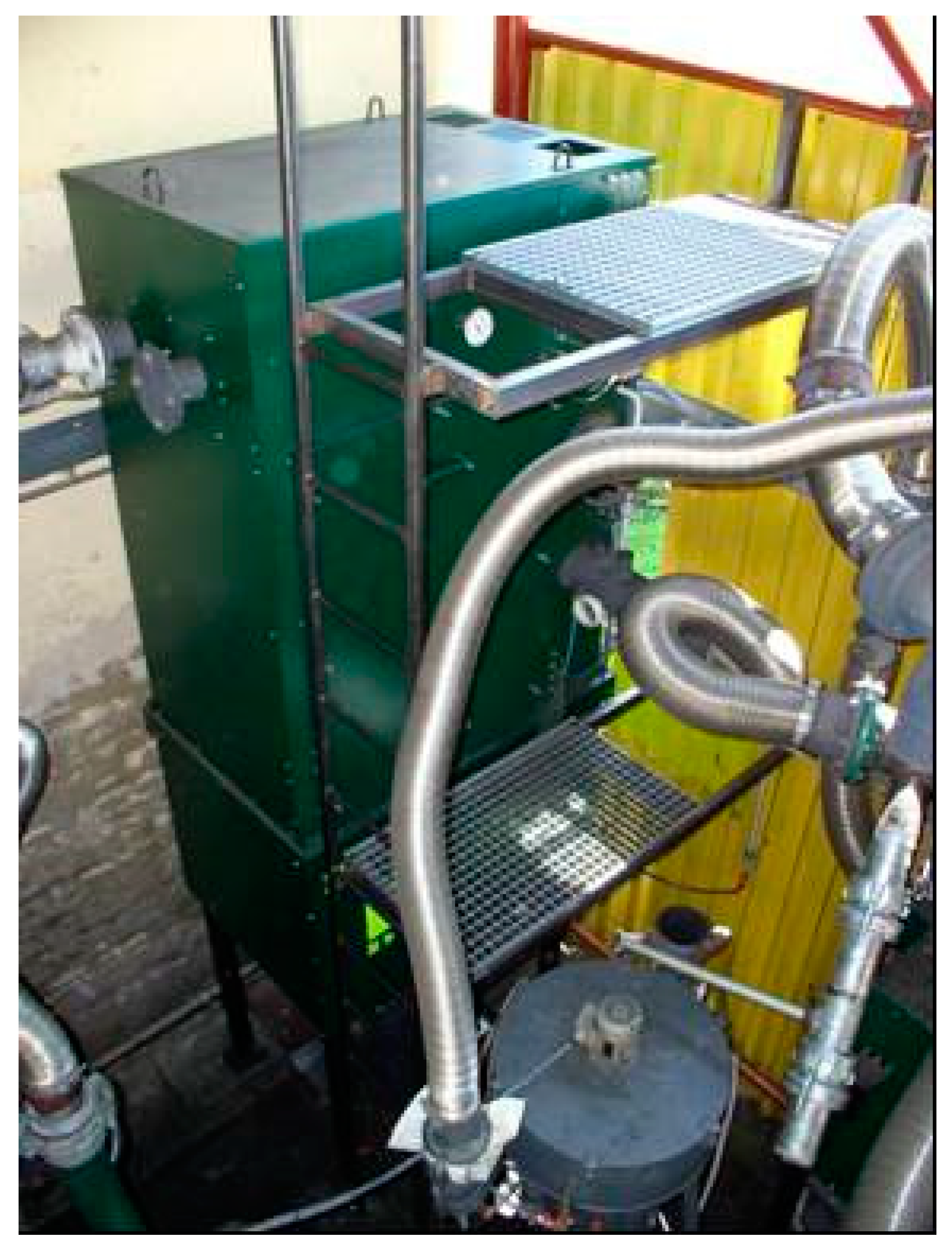
The offtake of gas from this generator was performed from the top section from the tube leading produced gas from the generator, to the gas cleaning system. A closure valve is located in the top section of the generator for its automatic filling using a high-lift container. Gas rising from the generator through the outlet channels (piping), with a temperature of approximately 250 °C, was routed to a collector connected to the gas pipe, which lead to the hot multi-cyclone and then to the technological line where the other equipment was located, including the monitored sleeve filter equipped with 15 textile sleeves (Figure 2) with a diameter of 20 cm and a length of 1.2 m. The total amount of trapped SP during the whole experiment was 10,282.1 g, which corresponds that 0.78 wt.% of fuel was converted into SP.
In compliance with the objectives of this task, one textile sleeve, which was tested for the cleaning of the generator gas for about one month, was taken for detailed analysis from the tested dry filter (Figure 3). The solid pollutants were carefully removed mechanically from its outer surface.
3.2. Fuel
The raw material processed in the generator were coniferous cuttings—maximum length 10 to 15 cm, maximum width 5 cm, and a maximum thickness of 2 cm. Their typical physiochemical properties are shown in Table 4. The proportion of fine particles and particles with bark in the gasified material was negligible. This fuel was used long-term in this unit. It was available, affordable, and had good quality and properties for gasification. This type of material had a medium agglomeration-slagging propensity [22].
3.3. Analytical Methods
Parameters of the fuel from Table 4 (moisture, volatile, and fixed carbon and ash) were measured by thermogravimetric analyzer Netzsch STA 449 F1 Jupiter. The heating rate was 10 °C/min in a nitrogen atmosphere up to 900 °C. For the amount of ash, there was a change in nitrogen by oxygen and heating continued up to 1200 °C. Ultimative analysis of fuel (amount of C, H, O, N and S) was measured by analyzer LECO CHN 628 with added module 628 S. Combustion heat was measured by the calorimeter LECO AC600.
Thermogravimetric analysis (TG) was measured by the analyzer Netzsch STA 449 F1 Jupiter. The heating rate was 10 °C/min in nitrogen atmosphere. The differential thermal analysis DTA was measured simultaneously, which measures the temperature difference between the standard sample (aluminium oxide) and the sample during heating.
Composition of the filtration cake inorganic fraction and incrust was measured with apparatus ARL 9400 XP+ equipped with a Rh lamp with a head Be-oxides window.
The distribution of the trapped particle size was performed by a Fritsch Particle Sizer Analysette 22 apparatus, where the light source is an He-Ne-laser with a wavelength of 633 nm and maximum measuring range of 0.1–1250 µm. To ensure the homogeneity of the measured sample and reliable statistics in the illuminated volume, the suspension was permanently mixed in an external mixing device during measurement using ultrasound, which provided for the separation of the agglomerate.
The measuring of organic substances composition trapped by the filtration cake was necessary to solve these substances in the solvent. Mechanically separated cake from the surface of the outer filter layer was inserted into the Soxhlet extractor and washed for four hours by acetone. The obtained solution was injected into the gas chromatograph Hewlett Packard HP 6890 with a mass detector Hewlett Packard MSD 5973 (GC-MS).
4. Results
4.1. Analysis of the Composition of the Filtration Cake
The solid pollutants were carefully removed mechanically from its outer surface. The sample of SP was tested by thermogravimetric analysis—see Figure 4—until 100 °C 1.5% by wt. was released into the stream of carrier gas, until 200 °C about 2.5% by wt., until 300 °C about 7.5% by wt., and until 400 °C about 8% by wt. The simultaneously performed DTA analysis found that there is only one significant endothermal effect, detected at approximately 725 °C. This effect is probably the melting of the inorganic fraction of the filtration cake.
The quantity of ash in the SP sample determined by its combustion at 850 °C was 37.28% by wt. The quantity of carbon dioxide in the sample determined using HCl corresponding to the detected carbonates was 2.7% by wt.
4.2. Composition of Inorganic Fraction and SP Size of the Filtration Cake
The results of the composition of the filtration cake inorganic fraction were performed using fluorescent X-ray analysis and are summarized in Table 5.
Measurement of the distribution of trapped particle size was performed for samples taken in the middle of four sleeves using the laser technique Analysette. The results are shown in Table 6. Particle sizes were in the range of 10 µm to 3 mm.
4.3. Analysis of Organic Substances Trapped by Filtration Cake
The next part of the research work was related to the identification and quantification of the components trapped in the filtration cake by the sleeves (Table 7).
4.4. Chemical Composition of Incrust
The composition of the incrust (Figure 5) shown in Table 8, where the concentration of the 16 most significant components from the 79 monitor elements is shown.
Evaluation of X-ray diffraction analysis assessing only the composition of the crystalline phase of the incrust is shown in Table 9.
5. Discussion
Fuel from woody biomass is a common commercial fuel but it has a higher amount of ash, e.g., woody pellets have only 0.15 wt.% of ash but coniferous cuttings could be contaminated by bark or pieces of soil.
From Table 5, it clearly follows that the dominant oxide of the inorganic fraction of SP are aluminum, calcium, and silicon oxide. The second most abundant component is potassium oxide, followed by manganese oxide, silica, ferric oxide, and sodium oxide. This table also clearly shows that phosphates and sulphates form an inconsiderable part of ash matter from biomass trapped in the filter. Chlorides represent only 0.1% by wt. in the monitored sample. A surprising result was the determined concentrations of heavy metals in the analyzed matter, particularly in terms of the toxicity of fly ash and its disposal and storage related to transport etc. This involves mainly copper, chrome, zinc, and manganese oxides.
The determined distribution of particle sizes of solid pollutants trapped by the sleeve filter from the raw generator gas produced by gasifying wood chips by air, demonstrated that their absolute size ranges from approximately 0.4 to 185 µm, whereas 99% by wt. of monitored particles were smaller than 100 µm. The proportion with a diameter up to 1 µm was approximately 1%, and up to 10 µm was approximately 22%.
The distribution of the individual mass fractions from 10% to 80% did not demonstrate any significant differences. The difference in particle size between 99 and 100% cannot be considered decisive due to the genesis of the sample.
Comparison of TG and GC-MS data shows that the results of thermogravimetric analysis do not correspond fully with the results of the performed identification. The sum of the weight of the individual identified tar components was substantially lower than the weight of substances released from the heated filtration cake in a nitrogen atmosphere. This could be caused by chemical sorption of organic substances on the SP, which could not be removed by the solvent.
The performed analyses of the incrust show that this is made up of mainly inorganic components of ash from the raw material gasified in the generator [23]. Its formation is defined significantly by potassium, calcium, and silicon oxides; and also phosphorus, iron, and magnesium oxides in the amorphous part [24].
Many of the identified oxides are typical components of ash matter forming low melting ash during combustion, or wood gasification. The relatively high silica content shows that this component was dosed into the generator with fuel during its preparation. One of its undesirable effects in the generator´s oxidation zone, where relatively high temperatures are present, is the formation of crystalline substances creating incrusts. An example of a K2O-CaO-SiO2 phase diagram is shown in Figure 6, where even the following eutectics can be found [25]:
K2Si4O9 765 °C
K8CaSi10O25 940 °C
K4CaSi3O9 950 °C
K4CaSi6O15 950 °C
K2SiO3 976 °C
K2Si2O5 1036 °C
To prevent similar undesirable conditions during the operation of cogeneration units, it is necessary to substantially limit its presence in the woody matter dosed into the generator. This applies to silica itself contaminating the tree bark or silica present in soil. The thermal conditions of decomposition of clay minerals must be considered: Kaolinite 450–700 °C, montmorillonite 600–700 °C, 800–900 °C, and illite 450–700 °C, 850–950 °C.
Author Contributions
Conceptualization, J.N. and P.B.; Data curation, J.N.; Funding acquisition, J.F.; Investigation, P.B. and S.S.; Methodology, S.S.; Supervision, J.N. and J.F.; Validation, J.K.; Visualization, V.P.; Writing—original draft, V.P.
Funding
This research was funded by Ministry of Education, Youth and Sports of Czech republic, grant number CZ.1.05/2.1.00/19.0389: Research Infrastructure Development of the Centre ENET.
Conflicts of Interest
The authors declare no conflict of interest. The funders had no role in the design of the study; in the collection, analyses, or interpretation of data; in the writing of the manuscript, or in the decision to publish the results.
References
- French, S.J.; Czernik, S. Catalytic pyrolysis of biomass for biofuels production. Fuel Process Technol. 2010, 91, 25–32. [Google Scholar] [CrossRef]
- Sheth, P.N.; Babu, P.V. Experimental studies on producer gas generation from wood waste in a downdraft biomass gasifier. Bioresource Technol. 2009, 100, 3127–3133. [Google Scholar] [CrossRef] [PubMed]
- Basu, P. Combustion and Gasification in Fluidized Beds, 1st ed.; CRC Press, Taylor and Francis Group: London, UK, 2006; ISBN 0-8493-3396. [Google Scholar]
- Babu, B.V.; Sheth, P.N. Modelling and simulation of reduction zone of downdraft biomass gasifier: Effect of char reactivity factor. Energy Convers. Manag. 2006, 47, 2602–2611. [Google Scholar] [CrossRef]
- Asadullah, M. Biomass gasification gas cleaning for downstream applications: A comparative critical review. Renew. Sustain. Energy Rev. 2014, 40, 118–132. [Google Scholar] [CrossRef]
- Chlond, R. Inhibitors in the gasification process. In Proceedings of the Conference Energy from Biomass X, Brno University of Technolog, Brno, Czech Republic, 25–26 November 2009; ISBN 978-80-214-4027-2. [Google Scholar]
- Reed, T.B.; Das, A. Handbook of Biomass Downdraft Gasifier Engine Systems; The Biomass Energy Foundation Press: Golden, CO, USA, 1988. Available online: https://www.nrel.gov/docs/legosti/old/3022.pdf (accessed on 15 December 2018).
- Lisý, M.; Baláš, M.; Špilácek, M.; Skála, Z. Operating specifications of catalytic cleaning of gas from biomass gasification. Acta Polytech. 2015, 55, 401–406. [Google Scholar] [CrossRef]
- Skoblja, S. Modification of gas composition from biomass gasification. Doctoral Thesis, Institute of Chemistry and Technology Prague, Prague, Czech Republic, 2005. [Google Scholar]
- Vakalis, S.; Moustakas, K.; Sénéchal, U.; Schneider, R.; Salomo, B.; Kurz, M.; Malamis, D.; Zschunke, T. Assessment of potassium concentration in biochar before and after the after-burner of a biomass gasifier. Chem. Eng. Trans. 2017, 56, 631–636. [Google Scholar] [CrossRef]
- Radina, O. Energy utilization of wood gas. Bachelor’s Thesis, University of West Bohemia, Pilsen, Czech Republic, 2013. [Google Scholar]
- Balas, M.; Lisy, M.; Moskalik, J. Biomass Gasification: Gas for Cogeneration Unit. Available online: https://www.researchgate.net/publication/281547834_Biomass_gasification_gas_for_cogeneration_units (accessed on 12 November 2018).
- Higman, C. Gasification; Elsevier: Amsterdam, The Netherlands, 2003; 391p, ISBN 07-506-7707-4. [Google Scholar]
- Morioka, H.; Shimizu, Y.; Sukenobu, M.; Ito, K.; Tanabe, E.; Shishido, T.; Takehira, K. Partial oxidation of methane to synthesis gas over supported Ni catalysts prepared from Ni-Ca/Al-layered double hydroxide. Appl. Catal. A Gen. 2001, 215, 11–19. [Google Scholar] [CrossRef]
- Li, D.; Wang, L.; Koike, M.; Nakagawa, Y.; Tomishige, K. Steam reforming of tar from pyrolysis of biomass over Ni/Mg/Al catalysts prepared from hydrotalcite-like precursors. Appl. Catal. B Environ. 2011, 102, 528–538. [Google Scholar] [CrossRef]
- Zhang, X.; Yang, S.; Xie, X.; Chen, L.; Sun, L.; Zhao, B.; Si, H. Stoichiometric synthesis of Fe/CaxO catalysts from tailored layered double hydroxide precursors for syngas production and tar removal in biomass gasification. J. Anal. Appl. Pyrolysis 2016, 120, 371–378. [Google Scholar] [CrossRef]
- Pravda, L. Energy gas–product of gasification. In Proceedings of the Energy from Biomass III, Brno, Czech Republic, 2–3 December 2004; ISBN 80-214-2805-8. [Google Scholar]
- Iaquaniello, G.; Mangiapane, A. Integration of biomass gasification with MCFC. Int. J. Hydrogen Energy 2006, 21, 399–404. [Google Scholar] [CrossRef]
- Sutherland, K. Filters and Filtration Handbook, 5th ed.; Butterworth-Heinemann is an imprint of Elsevier: Burlington, MA, USA, 2008; ISBN 978-1-8561-7464-0. [Google Scholar]
- Brandin, J.; Tuner, M.; Odenbrand, I. Small Scale Gasification: Gas Engine CHP for Biofuels; Linnaeus University: Växjö, Sweden, 2011; pp. 101–106. ISBN 978-91-86983-07-9. [Google Scholar]
- Henriksen, U.; Ahrenfeldt, J.; Jensen, T.K.; Gøbel, B.; Benzen, J.D.; Hindsgaul, C.; Sørensen, L.H. The design, construction and operation of a 75 kW two-stage gasifier. Energy 2006, 31, 1542–1553. [Google Scholar] [CrossRef]
- De Fusco, L.; Jeanmart, H.; Contino, F.; Blondeau, J. Advanced characterization of available not conventional mediterranean biomass solid fuels for ash related issues in thermal processes. Chem. Eng. Trans. 2016, 50, 229–234. [Google Scholar] [CrossRef]
- Šatava, V. Introduction to Physical Chemistry of Silicates, 8th ed.; SNTL Prague: Bratislava, Slovakia, 1965. [Google Scholar]
- Basu, P. Biomass Gasification and Pyrolysis: Practical Design and Theory; Elsevier: Amserdam, The Netherlands, 2010; ISBN 978-0-12-374988-8. [Google Scholar]
- Roedder, E. Silicate melt systems. Phys. Chem. Earth 1959, 3, 224–297. [Google Scholar] [CrossRef]
Figure 1.
Comparison of types of separators for trapping aerosol particles [19].
Figure 1.
Comparison of types of separators for trapping aerosol particles [19].

Figure 2.
Sleeve filter for trapping solid particles (SP).

Figure 3.
Fragment of sample of SP trapped by the filter.

Figure 4.
Thermogravimetric analysis (TG)/DTA analysis of filtration cake.

Figure 5.
Incrust from the grate section of generator.

Figure 6.
Detail of the K2O-CaO-SiO2 ternary system [25].
Figure 6.
Detail of the K2O-CaO-SiO2 ternary system [25].


Table 1.
Requirements for gas quality for gas turbines [17].
Table 1.
Requirements for gas quality for gas turbines [17].
| Parameter | Value |
|---|---|
| Minimum heating value (MJ.mn−3) | 4–6 |
| Minimum hydrogen content (% vol.) | 10–20 |
| Maximum supply temperature (°C) | 60–450 |
| Maximum concentration of alkali (ppb) | 20–1000 |
| Tar at inlet temperature | In gaseous phase or none |
| Sulphur (ppm) | <1 |
| HCl (ppm) | <0.5 |
| Maximum content of solid particles (ppm) | |
| Average >20 mm | <0.1 |
| 10–20 mm | <1 |
| 4–10 mm | <10 |
Table 2.
Requirements for gas quality for compression ignition and spark ignition engines [17].
Table 2.
Requirements for gas quality for compression ignition and spark ignition engines [17].
| Parameter | Value |
|---|---|
| Maximum hydrogen content (% vol.) | 7–10 |
| Maximum relative humidity (%) | 80 |
| Maximum supply temperature (°C) | 40 |
| Maximum ammonia content (mg/10 kWh) | 55 |
| Maximum tar content (mg·mn−3) | <100 |
| Maximum halogens content (mg/10 kWh) | <100 |
| Maximum content of sulfur recalculated to H2S (ppm) | 2000 |
| Maximum content of solid particles (mg·mn−3) | 5–50 |
Table 3.
Pollutant limits for Molten Carbonate Fuel Cells (MCFC) type fuel cells [18].
Table 3.
Pollutant limits for Molten Carbonate Fuel Cells (MCFC) type fuel cells [18].
| Parameter | Value |
|---|---|
| Maximum sulfur content (ppm) | <0.1 |
| Maximum ammonia content (% vol.) | <0.1 |
| Maximum hydrogen cyanide content (ppm) | <0.1 |
| Maximum chlorides content (ppm) | <0.1 |
| Maximum fluoride content (ppm) | <0.1 |
| Maximum tar content (ppm) | <2000 |
| Maximum particle size (μm) | <0.01 |
| Maximum lead content (ppm) | <1 |
Table 4.
Properties of used fuel.
| Parameter | Value |
|---|---|
| Moisture W r (wt.%) | 16.73 |
| Volatile combustibles V d (wt.%) | 82.99 |
| Fixed carbon F d (wt.%) | 16.71 |
| Ash A d (wt.%) | 0.30 |
| C (wt.%) | 49.86 |
| H (wt.%) | 6.14 |
| O (wt.%) | 43.38 |
| N (wt.%) | 0.31 |
| S (wt.%) | 0.01 |
| HHV, wet (MJ·kg−1) | 17.59 |
| HHV, dry (MJ·kg−1) | 20.52 |
r values of original wood sample; d dry sample without moisture.
Table 5.
Composition of the filtration cake inorganic fraction.
| Substance | Content (wt.%) | Substance | Content (wt.%) |
|---|---|---|---|
| Al2O3 | 16.73 | NiO | 0.07 |
| BaO | 0.83 | P2O5 | 5.54 |
| CaO | 16.71 | SO3 | 15.70 |
| CdO | 0.30 | SiO2 | 12.93 |
| Cl | 0.49 | SrO | 0.14 |
| Cr2O3 | 6.14 | TiO2 | 0.08 |
| CuO | 9.85 | Fe2O3 | 2.68 |
| K2O | 0.31 | PbO | 0.06 |
| MgO3 | 0.01 | ZnO | 1.47 |
| MnO | 7.59 | Na2O | 2.37 |
Table 6.
Cumulative particle size distribution of SP trapped by filtration cake.
| % | Sleeve 1 (g) | Sleeve 2 (g) | Sleeve 3 (g) | Sleeve 4 (g) |
|---|---|---|---|---|
| 1 | 0.935 | 0.665 | 0.692 | 0.676 |
| 2 | 1.366 | 0.943 | 0.976 | 0.963 |
| 5 | 2.628 | 1.624 | 1.670 | 1.654 |
| 10 | 4.846 | 2.606 | 2.795 | 2.659 |
| 15 | 7.043 | 3.574 | 3.921 | 3.664 |
| 20 | 9.234 | 4.572 | 5.000 | 4.703 |
| 25 | 11.497 | 5.585 | 6.704 | 5.762 |
| 30 | 13.939 | 6.622 | 7.110 | 6.811 |
| 35 | 16.598 | 7.707 | 8.159 | 7.872 |
| 40 | 19.526 | 8.804 | 9.252 | 8.925 |
| 45 | 22.631 | 9.977 | 10.389 | 10.017 |
| 50 | 25.934 | 11.252 | 11.628 | 11.168 |
| 55 | 29.517 | 12.646 | 12.972 | 12.381 |
| 60 | 33.293 | 14.244 | 14.481 | 13.745 |
| 65 | 37.052 | 16.121 | 16.228 | 15.3 |
| 70 | 41.191 | 18.487 | 18.325 | 17.204 |
| 75 | 45.754 | 21.618 | 21.000 | 19.776 |
| 80 | 50.654 | 25.909 | 24.461 | 21.029 |
| 85 | 56.602 | 31.498 | 29.001 | 35.043 |
| 90 | 63.754 | 37.17 | 35.792 | 47.127 |
| 95 | 74.544 | 46.917 | 46.012 | 58.692 |
| 98 | 85.998 | 55.385 | 56.700 | 69.138 |
| 99 | 93.76 | 60.362 | 63.296 | 75.364 |
| 100 | 183.788 | 102.15 | 106.200 | 112.657 |
Table 7.
Composition of organic substances captured on the filtration sleeve.
| Identified Substance | Content (µg/g) |
|---|---|
| Benzene | 30.4 |
| Toluene | 35.9 |
| m + p + o-xylene + ethylbenzene | 44.3 |
| Styrene | 0 |
| C3-benzene total (sat. + unsat.) | 0 |
| Others 1 | 78.7 |
| BTX total | 189.3 |
| Oxygen containing substances total | 180.1 |
| Phenol | 36.9 |
| Methylphenols | 15.1 |
| Dibenzofuranes * | 128.2 |
| Nitrogen containing substances | 0.0 |
| Indene+indan | 2.5 |
| Naphthalene | 63.6 |
| Methylnaphthalenes | 20.0 |
| Alkylnaphthalenes (alkyl >= C2) | 11.8 |
| Biphenyl | 15.5 |
| Acenaphthylene | 129.7 |
| Acenaphthene | 6.6 |
| Fluorene | 42.9 |
| PAH; m/z = 165–166 | 11.6 |
| Phenanthrene | 1470.0 |
| Anthracene | 314.7 |
| Methylfenathrenes+4H-cyclopenta[def]fenanthrene | 315.7 |
| Phenylnaphthalenes | 118.0 |
| Fluoranthene 2 | 1987.3 |
| Pyrene 3 | 1857.6 |
| Benzfluorenes | 46.3 |
| Methylfluorantene+methylpyrene | 164.7 |
| PAH of 4 circles ** (m/z = 226.228) | 4201.4 |
| PAH of 5 circles *** (m/z = 252) | 5851.0 |
| PAH of 6 circles **** (m/z = 276) | 2214.9 |
| other substances (TAR) | 538.5 |
| total TAR (excl. BTX) | 19564.5 |
1 this group includes other substances from the BTX and alkylbenzenes group. 2 together with fluorantene also includes fenantrylene M = 202 eluted from GC column immediately after it. 3 together with pyrene also includes aceantrylene M = 202 eluted from GC column immediately before it. * benzofurane, dibenzofuranes, methylbenzofuranes, naphtobenzofuranes. ** benz[c]fenanthrene, benzo[ghi]fluorantene,3,4-dihydrocyclopenta[cd]pyrene, cyclopenta[cd]pyrene. *** benzo[j]fluoranthene,benzo[k]fluoranthene,benzo[e]pyrene,benzo[a]pyrene,perylene. **** indeno [1,2,3-cd]pyrene,dibenzo[a,h]antracene,benzo[ghi]perylene,dibenzo[def,mno]chrysene and other PAH with M = 278–302.
Table 8.
Incrust composition.
| Oxide | Content (wt.%) | Oxide | Content (wt.%) |
|---|---|---|---|
| MgO | 3.11 | MnO | 2.02 |
| Al2O3 | 5.67 | Fe2O3 | 2.71 |
| SiO2 | 41.78 | CuO | 0.01 |
| P2O5 | 4.69 | SrO | 0.11 |
| SO3 | 0.06 | BaO | 0.16 |
| Cl | 0.03 | Na2O | 0.52 |
| K2O | 3.73 | TiO2 | 0.53 |
| CaO | 34.82 | NiO | 0.02 |
Table 9.
X-ray diffraction analysis results.
| Score | Name | Summary Chemical Formula | Content (%) |
|---|---|---|---|
| 58 | Silica | SiO2 | 23 |
| 46 | Calcite | CaCO3 | 13 |
| 46 | Calcium lime | CaO | 17 |
| 20 | Potassium Aluminium Silicate | K2SiAl2O6 | 8 |
| 22 | Carbon | C | 4 |
| 31 | Silica (other than above) | SiO2 | 1 |
| 22 | Sodium Calcium Aluminium Carbonate Silicate | Ca2Na2Si6Al6O12(CO3)0,5 | 33 |
© 2019 by the authors. Licensee MDPI, Basel, Switzerland. This article is an open access article distributed under the terms and conditions of the Creative Commons Attribution (CC BY) license (http://creativecommons.org/licenses/by/4.0/).
Share and Cite
MDPI and ACS Style
Najser, J.; Buryan, P.; Skoblia, S.; Frantik, J.; Kielar, J.; Peer, V. Problems Related to Gasification of Biomass—Properties of Solid Pollutants in Raw Gas. Energies 2019, 12, 963. https://doi.org/10.3390/en12060963
AMA Style
Najser J, Buryan P, Skoblia S, Frantik J, Kielar J, Peer V. Problems Related to Gasification of Biomass—Properties of Solid Pollutants in Raw Gas. Energies. 2019; 12(6):963. https://doi.org/10.3390/en12060963
Chicago/Turabian StyleNajser, Jan, Petr Buryan, Sergej Skoblia, Jaroslav Frantik, Jan Kielar, and Vaclav Peer. 2019. "Problems Related to Gasification of Biomass—Properties of Solid Pollutants in Raw Gas" Energies 12, no. 6: 963. https://doi.org/10.3390/en12060963
Note that from the first issue of 2016, this journal uses article numbers instead of page numbers. See further details here.