Bio-Inspired Robotic Solutions for Landslide Monitoring


Dipartimento di Ingegneria Elettrica Elettronica e Informatica, University of Catania, Viale A. Doria 6, 95100 Catania, Italy
Energies 2019, 12(7), 1256; https://doi.org/10.3390/en12071256
Submission received: 26 February 2019
/
Revised: 24 March 2019
/
Accepted: 29 March 2019
/
Published: 1 April 2019
(This article belongs to the Special Issue Robotics, Micronanosensor and Smart Devices for Control)
Abstract
:Bio-inspired solutions are often taken into account to solve problems that nature took millions of years to deal with. In the field of robotics, when we need to design systems able to perform in unstructured environments, bio-inspiration can be a useful instrument both for mechanical design and for the control architecture. In the proposed work the problem of landslide monitoring is addressed proposing a bio-inspired robotic structure developed to deploy a series of smart sensors on target locations with the aim of creating a sensor network capable of acquiring information on the status of the area of interest. The acquired data can be used both to create models and to generate alert signals when a landslide event is identified in the early stage. The design process of the robotic system, including dynamic simulations and robot experiments, will be presented here.
1. Introduction
Landslides are dangerous events that need to be carefully monitored to mitigate the risks to people. In general, hydrogeologic risk is taken into large consideration and plans for emergency handling are needed. The need to prevent and mitigate risks associated with landslide events is evident; therefore, adequate monitoring systems, which contribute to reducing risks by providing a better understanding of the dynamics of the phenomenon, are important. In the literature there are several solutions oriented to the creation of a network of sensors for monitoring, used both to acquire data needed to create predictive models of terrain dynamics and also to send alarms to activate emergency plans [1,2,3,4,5].
Landslides are characterized by movement; therefore, a distributed system, able to acquire the movement magnitude and velocity in the area of interest, is fundamental for all landslide analysis [6]. Different types of systems and techniques can be adopted to monitor ground surface displacements during landslide phenomena [7,8,9]. Among the available methods for landslide monitoring [10], we are proposing a hybrid solution that considers the deployment of geotechnical sensors to create an integrated monitoring system that can acquire information on a target area, using both deep earth probes and superficial sensors. The idea is to consider a limited number of high-cost sensors [11] that need a complex deployment; in fact, a drilling system is needed to place the probe under the ground with the aim of modeling the sliding phenomena of the terrain. Moreover, we can acquire useful data, including temperature, humidity, and inertial data, by placing a series of superficial sensors that can be distributed in the area, acting as nodes of a complex sensor network. Each node can include functionalities related to auto-calibration and self-repairing to improve the lifetime of the whole monitoring system [12]. Due to the nature of target terrains, often the desired target positions are not easily accessible to humans and robotic solutions represent the only possibility. The employment of autonomous mobile robots for the positioning of a wireless sensor network is a continuously growing research field. Often, robots need to perform cooperative simultaneous localization and mapping algorithms to detect the most reliable location for sensor release [13,14]. The solution proposed here has to be considered complementary to the employment of Unmanned Air Vehicles (UAV). In fact, UAV are important for the construction of a traversability map needed to identify the target locations for the deployment in the area and to provide the optimal routes for the Unmanned Ground Vehicles (UGV) responsible for the sensor positioning. UGV can release new nodes in the environment, repair malfunctioning nodes, or recharge the batteries of previously deployed ones. In some cases, the robot could act as a node itself [15].
In recent years, there has been a significant interest in the design of robots able to accomplish tasks with a certain degree of autonomy, in complex environments. Relevant problems to be considered include, among others, demining and terrain exploration and mapping [16]. Therefore, important aspects to be addressed to succeed in solving these tasks are: terrestrial mobility, efficiency in power consumption, robust navigation algorithms and control strategies, and reliable communication protocols. Terrestrial robots are classified into two main categories, wheeled and legged, which have different characteristics. Wheeled robots represent a standard and simple solution even if they cannot perform well in complex environments that require more adaptation and flexibility. Vehicles with wheels need a relatively simple controller and can move quickly over flat terrains. On the contrary, a major advantage of legged systems is the continuous passage between stance and swing phase, realizing discontinuous footholds. This capability is a clear advantage when facing real-world environments that include irregular and discontinuous surfaces.
Power consumption is an important element to be taken into account when we want to improve the autonomy of a robot.
In presence of wheeled vehicles, the autonomy requirement is more easily satisfied because of the relatively low energy consumption of these moving platforms. This problem is mostly present in legged robots that instead are characterized by a considerable energy requirement. However, this drawback is compensated for by the robustness of multi-legged robots that can continue moving also when some legs are not operative. This characteristic is not present in wheeled robots, where a fault in a wheel could be dramatic for robot mobility. Moreover, taking inspiration from nature and, in particular, from insects, we can improve the walking-robot performance reaching high-speed stable walking over rough terrains [17]. A good compromise that can merge both advantages of wheeled and legged robots is represented by a hybrid solution combining the simplicity of wheels with the climbing capabilities of legged systems. In the literature there are a few examples of robots that behave to this category: Prolero, Asguard, RHex, and Whegs are typical examples. Whegs are a series of robots with characteristic three-spoke appendages that combine the advantages of wheels and legs (i.e., whegs). One of the first examples of a robot designed following the locomotion principles of the cockroach was Whegs I [18]. It has a single drive motor and two small servo motors for steering. It is able to climb obstacles that are higher than 1.5 times the length of its legs. The next generation of whegs vehicle, called Whegs II, introduced a body joint to improve the performance of Whegs I [19]. This active joint was devoted to posture control in a way similar to the cockroach, increasing the climbing capabilities of the system.
Another important reference point for autonomous exploration is Asguard: a quadruped robot designed to show fast and adaptive locomotion [20]. This robot application field includes harsh outdoor environments for security and surveillance tasks. The wheel-leg design adopted in Asguard includes a five-spoke structure implemented in flexible material to improve the adaptability, reducing slipping on uneven terrains. The shape of end-effectors was further modified, reducing the number of spokes to one, in the robot called RHex [21]. The robot design allows it to reach high speed without attention to the robot stability due to its ability to move also when the robot is overturned.
On the basis of this state of the art, we proposed a new design focused on a modular structure that includes the flexibility of legged systems together with the reliability of wheeled ones.
The aim of the proposed work is to outline important elements taken into account during the design process of a bio-inspired robot able to navigate in unstructured environments to release the sensing nodes. The main aspects taken into account are related to the design of the mechanical structure, the choice of the suitable locomotion control system, the high-level decision-making algorithms and the optimization of the whole system for energy efficiency.
The design process of the mechanical structure considers the possibility of developing a modular system able to handle different types of terrains in order to deploy the sensor node in an assigned location. In the literature there are examples of different types of robots for exploration: worm-like, legged, rovers, etc. [22,23,24]. As previously discussed, we oriented towards a hybrid structure trying to incorporate the advantages of the different existing platforms [21,25,26]. The proposed robot includes articulated arms that can be configured in different ways to increase the number of basic behaviors available and to improve the climbing capabilities of the system.
The locomotion control is a fundamental aspect to be considered during the design phase. The idea is to develop, as a basic control unit, a dynamic system able to generate limit cycle solutions that can be modulated depending on the parameters to obtain either pseudo-harmonic or slow–fast dynamics. For the gait generation, we adopted a connection scheme based on diffusive coupling to obtain stable phase relations among the connected cells. The control network represents a central pattern generator (CPG) able to guarantee the coordination among the different actuators present in the robot obtaining stable locomotion patterns [27,28].
Self-assembly mechanisms will be taken into account as a suitable strategy to improve the basic capabilities of the system. Inspired by the swarm behaviors of social insects, there are several research trying to reproduce their collective behaviors in groups of robots that cooperate and self-organize together. A group of swarm robots able to self-assemble into a single articulated structure in response to terrain conditions, during autonomous exploration, is described in [29] whereas collaborative strategies to accomplish a task are presented in [30,31]. This aspect has been addressed and possible mechanisms will be presented.
It has to be underlined that a non-optimal deployment of sensor devices leads to either a bad network connectivity which deteriorates data communication and data logging; or overlapping of coverage which wastes resources and produces non-optimal data in the network. Algorithms for robot-assisted sensor deployment including path schedule, sensor placement algorithm, and minimum path planning will be adopted [32]. For the decision-making process, the bio-inspired approach is conceived to support the use of standard navigation techniques with strategies including motor-skill learning, sequence learning, attention and expectation that have been modeled to replicate the behavioral response of animals and are here used to improve the adaptation capabilities of the robotic system [33,34,35]. Energy efficiency will be performed improving the coordination among the different actuated modules composing the moving system and including actuated and passive joints to maximize the adaptation of the robot to different terrain configurations.
The rest of this study is organized as follows: the mechanical design is presented in Section 2. In Section 3, locomotion and control systems are investigated and discussed. In Section 4 simulation results are provided and in Section 5 experiments with a robotic prototype are illustrated. Finally, in Section 6, conclusions are drawn.
2. Mechanical Design
In a robot, mechanical design is constrained by several needs, including primarily both the tasks that the robot is asked to accomplish and where these tasks have to take place. Due to the complexity of the exploration in an unstructured environment, the robot here presented has been designed using a modular approach. Depending on the tasks to be accomplished and on the environment, robots with different combinations of basic modules can be considered. Aspects related to weights and dimensions will not be discussed in this work, due to the fact that depending on the application scenario the robot can be scaled in dimension accordingly. The different aspects taken into account and the proposed solutions are here detailed.
2.1. Wave-Based Motion
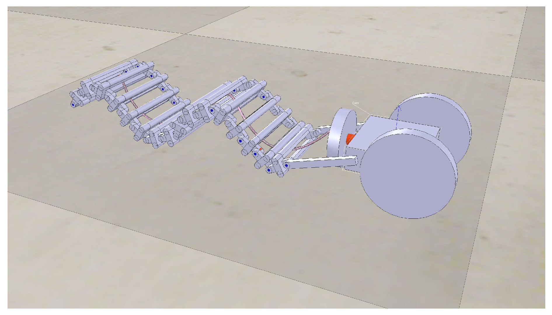
To enhance locomotion capabilities, a wave-induced forward-thrust module for the robot was designed and tested. In the literature, wave-like robots have been considered to allow locomotion on different kinds of terrains thanks to the multiple contact points that improve the forward thrust [36,37]. An interesting example is the single actuated wave-like robot realized and tested to move in several types of terrains and pipe lines, and also to swim [26]. As far as bio-inspiration is concerned, undulatory locomotion is preferred by living beings when engaging terrains with very different grounds (e.g., sand, gravel, rocks). Classical examples are snakes and microorganisms, the latter exploiting flagellar motions in very complex viscous media [38]. The first robotic module designed, simulated, and built, inspired by [26] and introduced in [39], is a suitable compromise between these two locomotion types. In fact, exploiting wave generation mechanisms for locomotion adopted by flagellates, an interaction between a rigid spiral actuated tail and a series of external passive vertebrae was realized (see Figure 1). A spiral wave is transformed into a series of parallel plane waves used to generate a strong forward thrust in practically every type of terrain. This characteristic is essential while moving on uncertain grounds. The robotic module can move forward and backward by producing a continuously advancing wave. Moreover, this basic locomotion is realized using only one actuator, a DC motor endowed with a basic speed controller. In addition, a front cart with passive wheels is included. This is useful to endow the robot with a suitable tank to carry the control boards, batteries, and the sensory boards to be delivered in the area.
To evaluate the structure, the model was realized and simulated in a dynamic simulation environment called V-Rep [40]. This module, dedicated to forward thrust, is useful on terrains subject to landslides that can includes steep climbs. In these conditions, the presence of multiple contact points could be an important element to reduce slippage.
2.2. Wheel-Leg Hybrid Structure
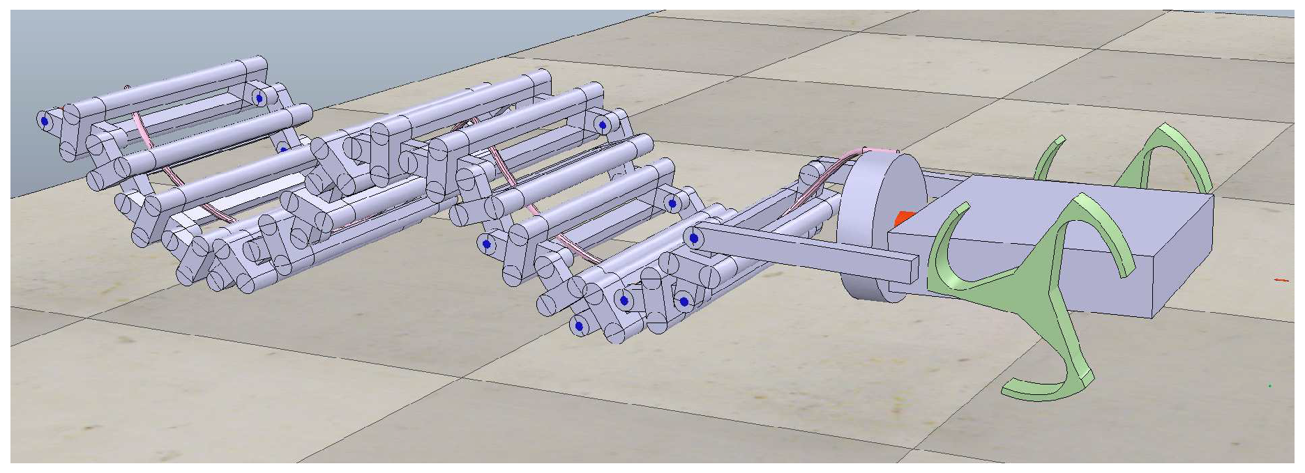
The cart needed to store the power supply and the control boards was initially endowed with passive wheels. To enhance the locomotion efficiency of the system, we introduced, instead of standard wheels, a particular structure named whegs that is a three-spoke wheel that can enhance the efficiency of the robot on uneven terrains (see Figure 2). The effect of this hybrid design was successfully tested on different prototypes [41,42,43].
This particular design aims to exploit the advantages of both wheeled and legged robots: the zero energy consumption of wheels (in holding the vertical robot weight force component) and the versatility of legs (for locomotion on uneven terrains). Therefore, we are migrating from passive wheels to active whegs to improve the behavioral capabilities of the robotic system. Moreover, as discussed in detail in Section 4.1, the presence of active whegs allows the inclusion of steering maneuvers otherwise unavailable when only the wave-based motion is considered. The inclusion of this actuation mechanism allows the robot to follow the desired path to reach the delivery place identified for the release of the sensor board for landslide monitoring.
2.3. Dexterous Multi-Joint Manipulators
To further enhance the dexterity of the robot we analyzed the possibility of including a module with a pair of multi-joint manipulators as shown in Figure 3 on the basis of the experience gained in the Tribot design [25].
The presence of either a two- or three-degree of freedom (DoF) manipulator improves the maneuverability of the system in particular for the fine positioning, the climbing capabilities, and steering mechanisms, and introduces the possibility of grasping objects. The grasping capability has several potential applications; in fact, depending on the ongoing task, the robot could need either to carry an object from one place to another or to move it in order to open a path. An articulated arm can also be useful during the sensor node deployment for refining the final positioning, moving the sensor board on the target location. Manipulators can be treated as legs to improve the climbing capabilities of the system to overcome obstacles in specific environments (e.g., a staircase-like scenario). Therefore, the proposed design tries to mix the advantages of different solutions endowing the robot with a complete behavioral repertoire to be used in specific tasks.
2.4. Body Joints
The modular approach followed for the robot design needs a strategy to connect the different modules included in the final configuration. To solve this problem, a series of body joints was included as shown in Figure 4. Looking to the insect world (e.g., honey bees), this is a common solution adopted to connect the different body parts: head, thorax, and abdomen. The parts, as in our case, have different purposes and need to move independently to each other. The joints are active but contain a high degree of elasticity that guarantees smooth behaviors and improves the power efficiency of the whole structure. Overall we have three main modules (i.e., tail, whegs cart, front manipulators) that are connected with a pair of joints with 2 DoF each. With this configuration the robotic structure shows a high level of adaptation to different terrain morphologies and an improvement in dexterity during steering maneuvers with a considerable optimization in energy efficiency.
2.5. Self-Assembly
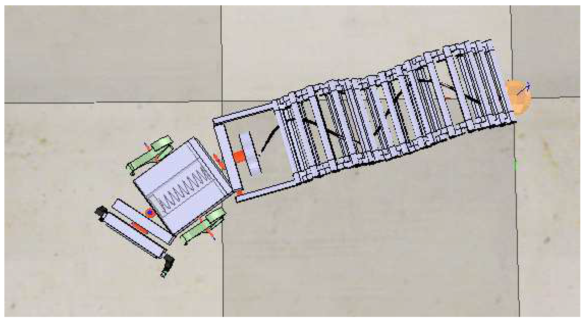
To work on uneven terrains, a robot needs to overcome obstacles including gaps. A simple solution consists of the addition of a second tail attached to the robot for reaching the other side of a gap and to sustain the weight during the crossing (see Figure 5). However, this new behavior introduces more complexity in the robotic structure and produces a series of pejorative effects during the standard navigation that should be taken into account. Moreover, it can be noticed that this climbing capability is not always needed. For these reasons, we investigated the possibility of including self-assembly mechanisms to improve the single-robot capabilities only when needed.
The animal world is rich with examples related to coupling mechanisms. Several species of terrestrial snails thread the coupling organ into the partner’s body during mating and a similar mechanism is adopted by octopuses. Similar procedures are technically implemented during the transfer of fuel between air vehicles during flight.
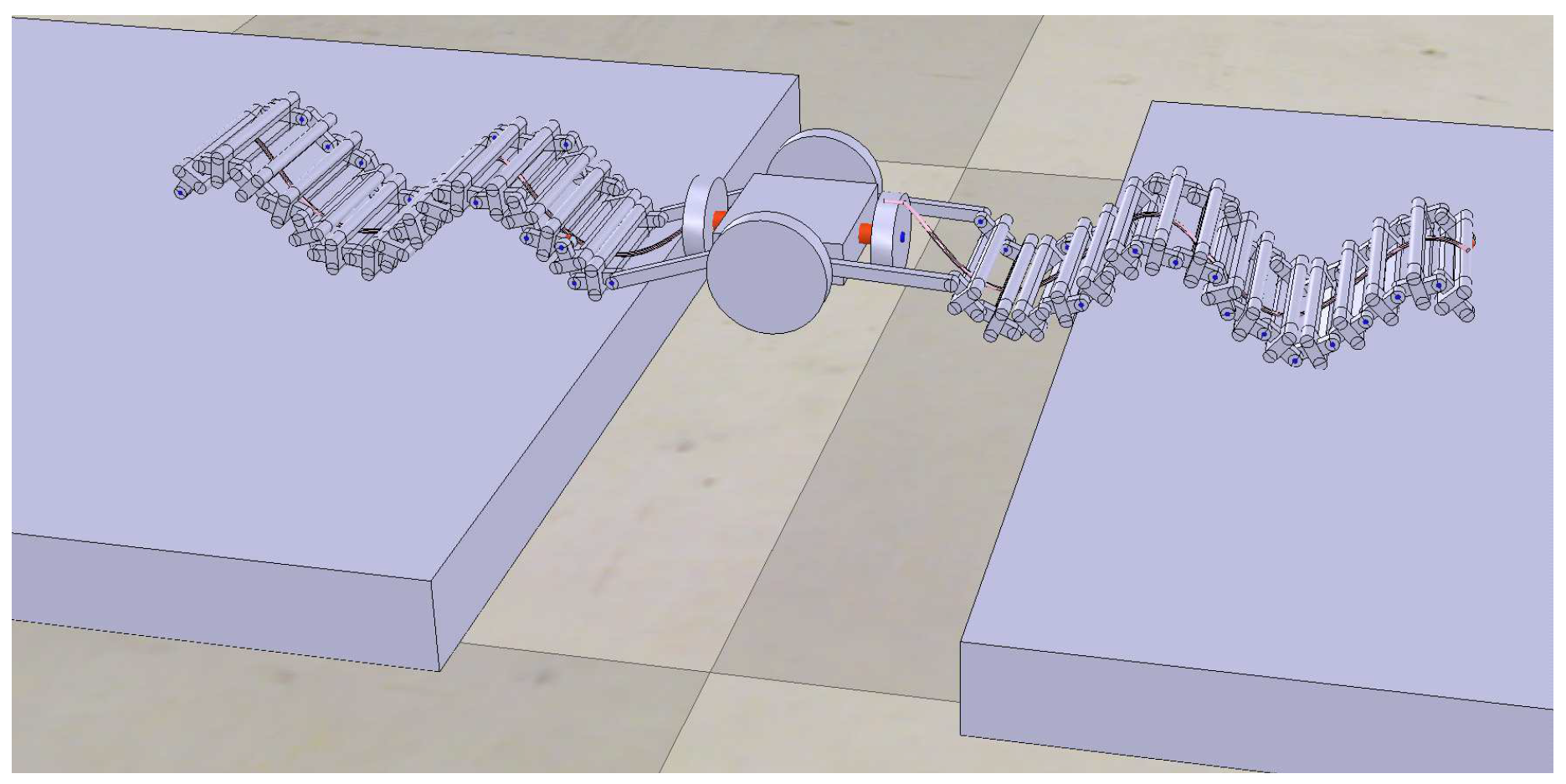
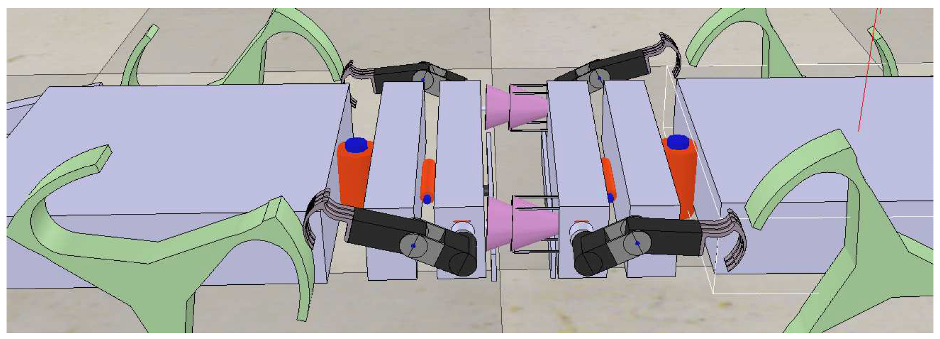
A suitable self-assembly mechanism can allow two robots to constitute a unique entity (see Figure 6). If the robots assemble though their heads, the center of mass will be located in a neighbor of the two carts. This allows the robot to lean towards the opposite side of the gap without losing stability. The capability to self-assembly will be exploited in view of particular needs while moving towards a target location for releasing a sensor node.
In our model a “male” robot is endowed with two rods and a “female” one with two couples of co-axial cones, one cone overlying the other. The rods can assume two configurations: they start with a smooth shape that can enter in the cone of the other robot and then a touch sensor triggers the opening of four fins in order to perform a coupling mechanism. The particular configuration of the female robot permits blocking of the rods in the middle of the two cones. The assembled system allows the discovery of new paths that are otherwise inapproachable. The idea is to modify the traversability map, depending on the robot skills, to find the optimal route for visiting all the target locations for the development of the sensor network.
2.6. Sensor Deployment
Depending on the type of terrain, different release mechanisms for the sensor nodes transported by the robot can be adopted. Typical examples are gluing mechanisms that can be preferred in presence of rocks and other mechanical anchoring mechanisms. In nature, female fishes expel eggs that are immediately fertilized by the male. The deposition can take place in different ways: deposition in free water when fertilized eggs are dropped in the water, and deposition of adhesive eggs when object present in the sea floor are used as a solid substrate for the release.
A first solution can be related to a dust-like release procedure [44] that can be for instance directly performed from UAV. A second solution, instead, is needed if we want to optimize the sensor network deploying the nodes on specific target locations. We included in the central module (i.e., the cart with whegs) a simple releasing mechanism based on a revolute joint and a helix with a specific slope that facilitates the deployment of the boards. The system can carry multiple nodes that can be distributed along the travelled path. An air jet can be also used to clean the location and smart probes (e.g., similarly to the insect antennae [45]) can be adopted to identify the type of terrain in order to find a suitable place where the sensor node can be placed using the selected anchoring mechanism.
3. Locomotion Control System
The locomotion control of a hybrid system is a challenging task. Due to the complexity of the terrain subject to landslide, we need a fast and reactive response that suggests the application of a centralized control system.
For hybrid machines, traditional motion control approaches will have to be adapted. In fact, the single rotational DoF of moving whegs is paired with the concurrent actuation of different links constituting the robot legs in specific phase relations among each other. We worked to develop a CPG where the core element is a dynamic system that can handle each single module of the actuation system: the two front legs, the two whegs, the tail and the body joints.
A CPG is a functional unit able to generate motion rhythms: it provides the feedforward signals needed for locomotion, and the presence of sensory feedback and high-level control signals is not necessary. The CPG-based control was successfully applied in different bio-inspired systems from bipeds to hexapods [46,47,48,49]. CPGs can be realized through networks of coupled nonlinear systems and the different locomotion gaits can be obtained by changing the coupling parameters. To control the overall robotic structure, all the motor neurons need to reach a given phase-shift synchronization in a steady state condition supported by a travelling wave pattern [50].
The design of a basic active cell is the first step to develop a neural network for locomotion control. With this aim the following second-order cell was considered:
being . It was demonstrated that such a cell, for a suitable selection of its parameters (, , and , ), is able to generate a stable slow-fast limit cycle [36].
The successive step consists of creating a network that can be treated as a dynamic graph. Let us consider a network organized in a directed diffusive tree graph.
where: represents the dynamic of the uncoupled oscillator; the second part of the equation represents the diffusive element that is restricted to all connected oscillators j; k is the feedback gain, whereas the argument of the sum contains the error between the state variables of the and when a phase-shifted is applied via the rotational . Two oscillators are in equilibrium only when the diffusive term is zero, which implies that a phase-shift synchronization was reached.
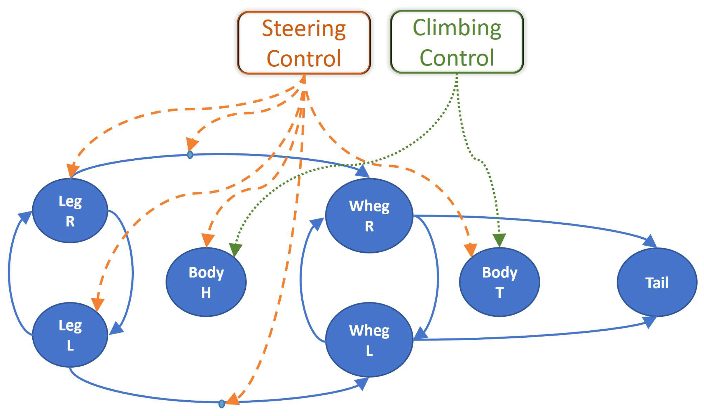
The locomotion control network is described in Figure 7, where each actuated unit is controlled by a node that can influence, through direct connections, other nodes, creating a synchronous activity. The double-legs module is controlled through two neurons (i.e., and ), similarly to the whegs module (i.e., and ) and finally for the tail a single neuron is needed (i.e., ). To optimize the forward movement of the robot, we need to balance the total forces acting on the robot that come from the contributions of three different blocks: frontal legs, whegs, and tail. To avoid slipping, all the modules need to be tuned to provide a coherent speed vector to be applied to the system. This can be obtained by analyzing separately the three blocks and calculating a scaling factor for the velocity and applying it to the dynamic of the CPG.
For the body joints we can use the same basic units modifying the limit cycle behavior, collapsing the oscillatory dynamics into equilibrium points through a simple change of parameters [51]. The principle is to connect the oscillators using direct links imposing a phase relation through rotational matrix, for instance we want that the left and right legs are in anti-phase during locomotion therefore an with can be applied. The relation between the state variables of the dynamic control system and actuators is performed through an adaptation block as described in [52].
We can generalize this type of Laplacian diffusive connections using time-varying rotational matrix () in order to tune the whegs motion with the leg stepping, compensating the differences of the two kinematics structures. We can apply the same strategy to the tail taking into consideration the desired robot speed and the relations between the oscillator frequency and the tail wave length. The stability of locomotion gaits can be treated using the Contraction Theory, introduced in [53], and later on extended to Partial Contraction [54] that we already successfully applied in a hexapod robot whose CPG was developed using the same basic oscillators [28,55]. This efficiently handles the problem with exponential convergence to behaviors and to specific relations among the state variables of the control system. Finally, descending commands for navigation control and behavior selection (e.g., steering and climbing control), can modify the network dynamics by selecting the suitable parameters at the level of neurons and connection to be tuned [51,56].
4. Simulation Results
The preliminary evaluation of the developed robotic system was performed using a dynamic simulation environment. The simulation platform taken into account is the V-REP environment developed by Coppelia Robotics [40]. This environment can be interfaced with other programming languages using the available API; therefore, the control network was developed in MATLAB. In the following the steering and climbing behavior of the robot is evaluated and a discussion of the energy efficiency is reported.
4.1. Steering Control
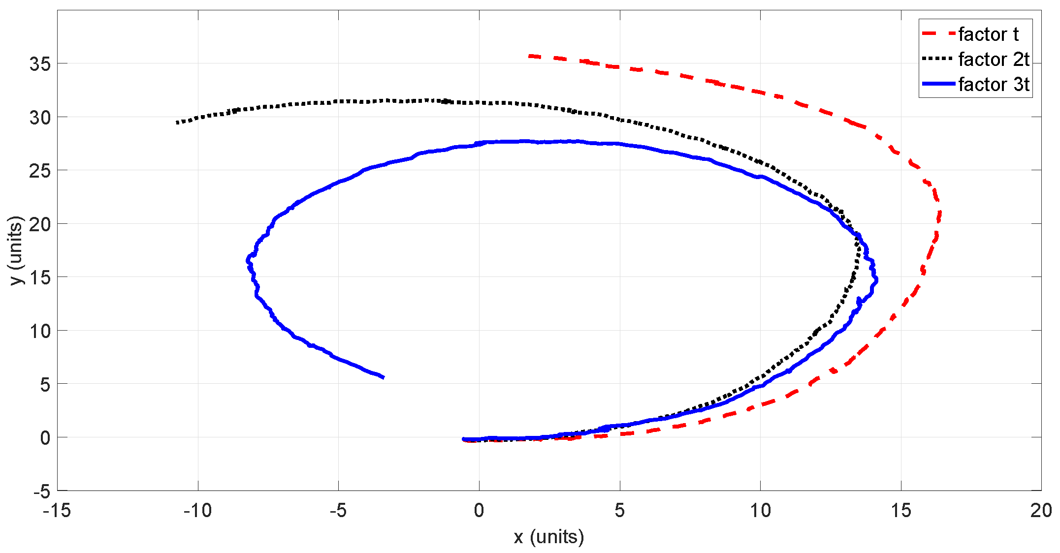
In nature, animals adopt different strategies to realize either a steering or a turning on the spot behavior. Looking to the insect world, turning is achieved by decreasing the step lengths on the inner side. Acting on the CPG we can modulate the amplitude of the steps for the legs module and, at the same time, we can change the speed of the whegs accordingly. The whegs speed is regulated by the time-dependent rotational matrix .
To facilitate the steering maneuver, both body joints, located at the head and tail of the robot, are actuated in order to be complaint with the ongoing movement. Figure 8 shows the robot trajectory performed with different rotational matrices that generate distinct curvature radius.
4.2. Climbing Control
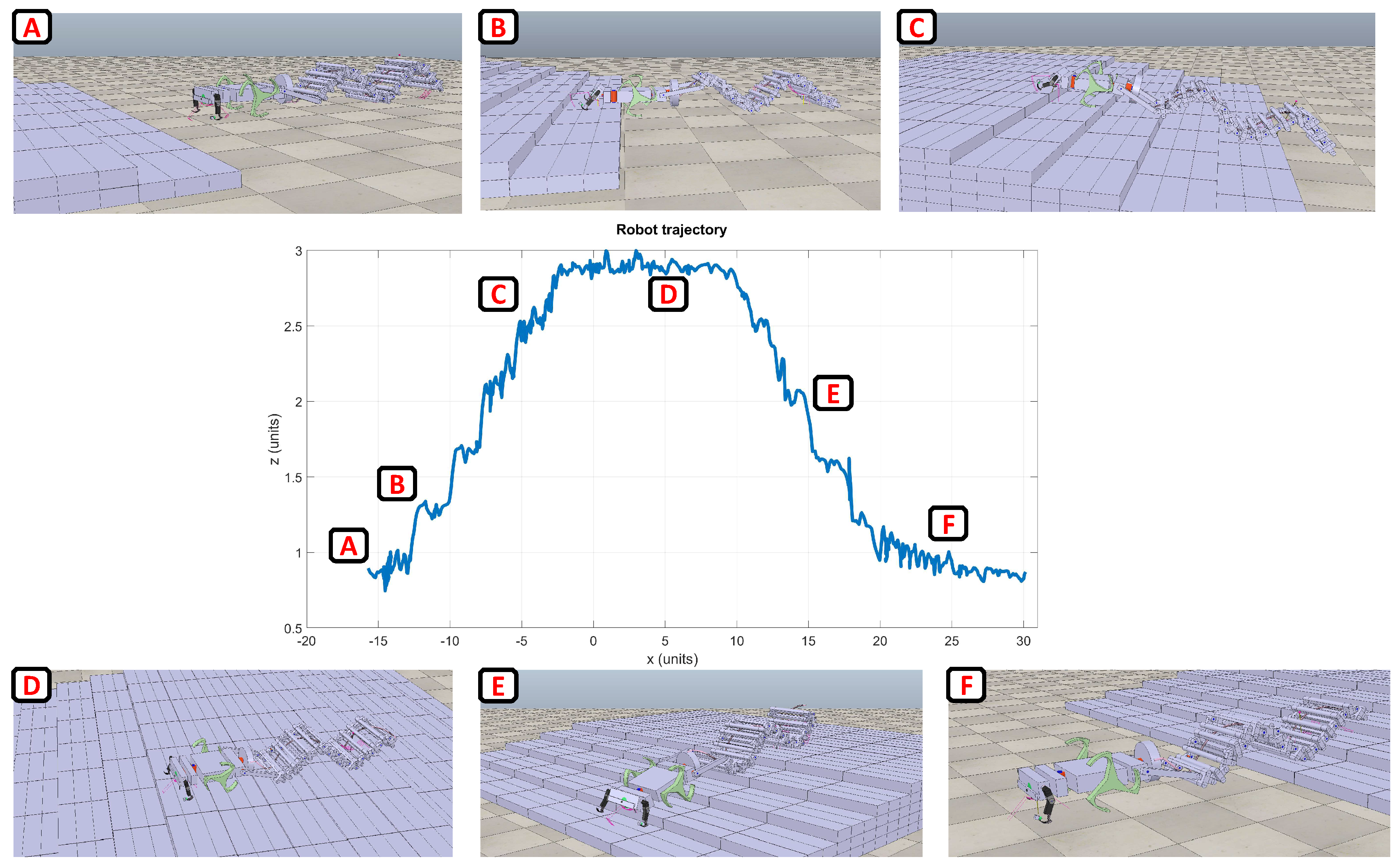
To evaluate the climbing capabilities of a single complete robotic system, a stair-like obstacle was considered. The robot is requested to go up and down overcoming the obstacle without losing stability. Also, in this case the role of the body joints is important in fact, by using simple proximity sensors, the system can evaluate the shape of the terrain modifying its posture to improve its adhesion to the ground.
In Figure 9 the trajectory performed while accomplishing the task is shown together with a series of snapshots illustrating the robot in action.
The stability of the robot can be also evaluated using the roll, pitch and yaw angles as reported in Figure 10. After climbing the direction of motion is slightly different from the beginning (i.e., yaw angle) but the presence of a GPS system together with an inertial module on board will help in re-orienting the robot for reaching the target location where the sensor board has to be deployed [57].
4.3. Specific Resistance
An important parameter to be considered when developing a roving system is related to the power efficiency that allows the comparison among systems that adopt different forms of locomotion The “Specific Resistance”, , is a measure proposed originally by Gabrielli and von Karman [58] in 1950:
where m is the robot mass, g is the gravity constant, P is its average power consumption at a particular speed, v.
Specific Resistance is often called cost of transport and can be used to compare vehicles independently from their size, speed, or configuration. The obtained value is related to a coefficient of friction, the lower the value, the more ‘efficient’ the transport mode is. Table 1 reports the typical values of the “Specific Resistance” obtained for different robotic platforms performing standard tasks like normal walking, high-speed movement on a flat terrain, and obstacle climbing.
RHex robot Specific Resistance ranges between [59], while for Gregor I, an asymmetric hexapod robot inspired by a cockroach [60], the performance on uneven terrains was [61]. The robot MiniHex has a Specific Resistance on even terrain of [62]. The robot SAW requires for crawling an [26]. The results for the Tribot robot, a hybrid system with whegs and arms, , refers to high-speed locomotion on flat terrain, while an obstacle climbing task that needs both wheels and manipulator produces a cost of transport . We expected that the Specific Resistance for the here proposed hybrid system will range between the Tribot and the SAW robot and it can be considered more than acceptable. Moreover, the effectiveness of bio-inspired decision-making strategies already tested on other robotic systems will be evaluated [63,64].
5. Robot Experiments
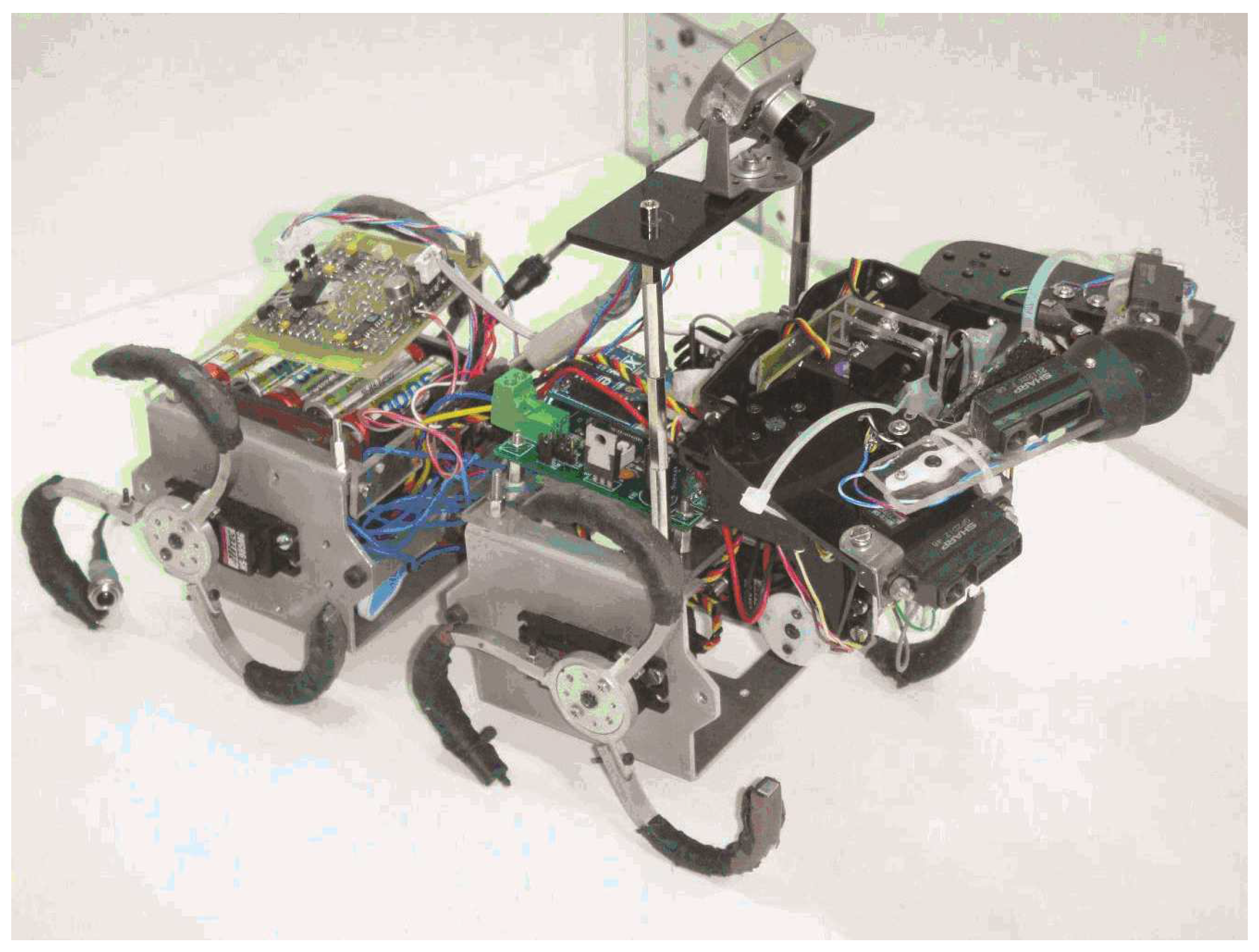
To acquire a preliminary feedback from a hardware implementation of the proposed robot, a modular structure including two wheel-legs modules and a two-arms manipulator (Figure 11), adapted from the Tribot robot [63], was tested. The two modules equipped with whegs are connected by a spring-based passive joint whereas an actuated joint is used to connect the front manipulator with the other modules. The front module contains of two arms with three degrees of freedom. The active joint is used to modify the manipulator configurations either improving locomotion capabilities when the arms are used as legs, or allowing object manipulation such as grasping when the manipulator is placed in the upper position. The mechanical structure is mainly developed using aluminum and plexiglass; these materials have been selected to guarantee a light weight for the robot. Relevant technical information including the robot mechanical characteristics are reported in Table 2.
The robot prototype dimensions in cm are (length × height × width). It is composed of different mechanical elements designed following the guidelines previously introduced. There are four wheel-legs, each one composed of three spokes that describe a circle of 12 cm (diameter) with a thickness of 6 mm. The spokes can be moved in two different directions: if each spoke faces the convex part towards the motion direction, the movement results to be smoother because the wheel-leg has a quasi-continuous contact with the terrain. While, the opposite configuration is better in overcoming obstacles because it increases the grip with the terrain. Two modules were designed to host the four whegs together with motors, electronics, and batteries. They were realized in aluminum with dimensions in mm (length × height × width). The front manipulator, connected to one of the whegs module via an actuated joint, consists of two legs each one with three degrees of freedom. In particular, the tibia is a rectangular piece of plexiglass with dimension in mm . The femur is completely built in plexiglass, it is a rectangular piece with dimension in mm . The first segment of the manipulator, called coxa, has to support notable mechanical stress, especially during the extension of the arms. For this reason, it was realized in aluminum with dimension in mm .
The modularity presents in the mechanical structure is also applied to the control system. Two microcontrollers are dedicated to handle motors and sensors distributed on the robot. Furthermore, a wireless communication with a computer is used to retrieve data and provide motor commands elaborated by high-level control algorithm. The principal control board is placed in the central module. It is dedicated to control the servomotors used to actuate the whegs. Moreover, the board acts as a communication bridge between the computer and the other microcontrollers used to actuate the other modules like the front manipulator. The selected microcontroller is an ATmega64, a low-power CMOS 8-bit system based on the AVR enhanced RISC architecture.
The front manipulator is handled by a similar controller used to generate the PWM signals needed by the six servomotors present in the manipulator and to the servomotor that realizes the active joint connecting the manipulator with the other modules. The board placed in the front manipulator is also dedicated to acquiring data from the distributed sensory system embedded in the robot. In fact, on the robot arms, four distance sensors are included for obstacle avoidance and several micro-switches are adopted for collision detection and object grasping. The sensory system currently also includes an inertial module and a camera. With the currently used battery packs the autonomy of the robot is approximately between 30 and 45 min depending on the complexity of the terrain and the use of the front manipulator. However more performing batteries are now available on the market and the autonomy can be further improved.
A preliminary test on the robot performance was devoted to the evaluation of the maximum speed. The motors that actuate the wheel-legs are Hitec HS-985MG that have been modified to allow continuous motion. Their nominal speed is 0.13 s/60, therefore, the time needed to perform a complete rotation is 0.78 s. Since the circumference of a wheel of the robot is about 37 cm, the nominal speed of the robot is 47 cm/s. Moreover, each wheel of the robot is characterized by three spokes, which are out-of-phase by 120 degrees and the support surface of each spoke during the movement is about 4 cm.
A compliant leg design is able to climb over obstacles higher than the dimension of the wheel axis. A theoretical value for a wheel-leg approach can be evaluated using Equation (4):
with r naming the radius of the wheel-leg (about 6 cm) and the angle between the horizontal and the support point with the obstacle that results to be about 30. Therefore, theoretically, the highest surrounding obstacles with this structure results to be 9 cm. Experimental tests were done to verify this hypothesis. Using only three-spoke wheels the robot is able to nimbly overcome obstacles up to 8 cm.
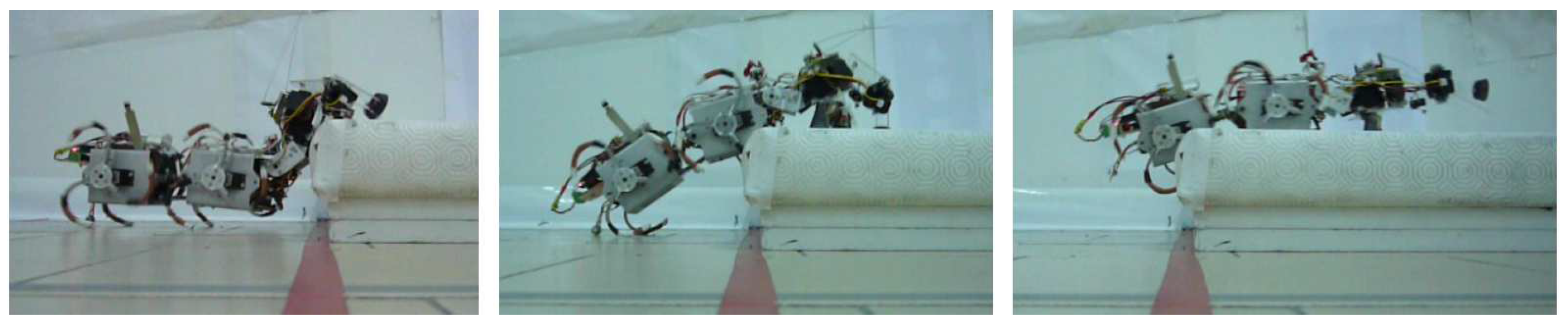
Therefore, in the presence of an obstacle higher than 8 cm, whegs are not enough to accomplish the overcoming task. In this situation the inclusion of the front manipulator is fundamental; in fact it allows the reaching of the top part of the obstacle with the robot arms. Using this system, the robot is able to overcome obstacles of about 11 cm (Figure 12). It has to be noticed that when the robot has to overcome a high obstacle, it risks falling down. To avoid this, changing the position of actuated joint is important in order to control the barycenter of the structure; this allows improved stability during climbing.
The robot was also tested on an uneven terrain where the front module is used when a deadlock situation is identified. Multimedia material on the experiments is available on line [65]. The inclusion of the tail and the assembly mechanism can further improve the system, adding other relevant behaviors to be used when specific conditions are detected.
6. Conclusions
This work is oriented towards the application of robotic architectures for human safety through helping to realize a suitable network of sensors for monitoring terrains subject to landslides. The positioning of these sensors is often quite dangerous for humans and bio-inspired robots are a suitable solution [32,64].
The design guidelines for a versatile robot oriented to navigation on uneven terrains are discussed. The modular structure of the system guarantees high flexibility depending on the different types of terrains to be faced. In fact, three different types of locomotion were considered: wave-based, legged-based, and whegs-based.
Moreover, we discussed the possibility of self-assembling multiple systems to improve single-robot capabilities. The system is controlled through a CPG based on oscillatory units connected to obtain synchronization among the activity of the different actuated modules. Simulations showing the steering and climbing capabilities of the system are reported for a preliminary evaluation of its performance. On the basis of the characteristics of the hybrid system, comparing them with other existing prototypes, we expect a good compromise on energy efficiency evaluated in terms of cost of transport. Finally, climbing experiments with a robotic prototype including whegs and articulated arms are reported to demonstrate the feasibility of the hardware implementation of the designed system.
Funding
This research was funded by MIUR project CLARA-Cloud platform for LAndslide Risk Assessment grant number SNC_00451.
Acknowledgments
The author acknowledges the support of Paolo Arena for his helpful discussions and S. Taffara for his contribution to the dynamic simulation of the robot.
Conflicts of Interest
The authors declare no conflict of interest.
References
- Rosi, A.; Berti, M.; Bicocchi, N.; Castelli, G.; Corsini, A.; Mamei, M.; Zambonelli, F. Landslide monitoring with sensor networks: Experiences and lessons learnt from a real-world deployment. IJSNet 2011, 10, 111–122. [Google Scholar] [CrossRef]
- Giri, P.; Ng, K.; Phillips, W. Wireless Sensor Network System for Landslide Monitoring and Warning. IEEE Trans. Instrum. Meas. 2018, 1–11. [Google Scholar] [CrossRef]
- Versace, P.; Capparelli, G.; De Luca, D.L. TXT-tool 2.039-4.2 LEWIS Project: An Integrated System for Landslides Early Warning. In Landslide Dynamics: ISDR-ICL Landslide Interactive Teaching Tools: Volume 1: Fundamentals, Mapping and Monitoring; Sassa, K., Guzzetti, F., Yamagishi, H., Arbanas, Ž., Casagli, N., McSaveney, M., Dang, K., Eds.; Springer International Publishing: Cham, Switzerland, 2018; pp. 509–535. [Google Scholar] [CrossRef]
- Giorgetti, A.; Lucchi, M.; Tavelli, E.; Barla, M.; Gigli, G.; Casagli, N.; Chiani, M.; Dardari, D. A Robust Wireless Sensor Network for Landslide Risk Analysis: System Design, Deployment, and Field Testing. IEEE Sens. J. 2016, 16, 6374–6386. [Google Scholar] [CrossRef]
- Papadopoulou, I.; Savvaidis, P.; Tziavos, I. Using the SyNaRMa system as a disaster management tool. Nat. Hazards 2011, 57, 453–464. [Google Scholar] [CrossRef]
- Casagli, N.; Cigna, F.; Bianchini, S.; Holbling, D.; Fureder, P.; Righini, G.; Conte, S.D.; Friedl, B.; Schneiderbauer, S.; Iasio, C.; et al. Landslide mapping and monitoring by using radar and optical remote sensing: Examples from the EC-FP7 project SAFER. Remote Sens. Appl. Soc. Environ. 2016, 4, 92–108. [Google Scholar] [CrossRef]
- Savvaidis, P.D. Existing Landslide Monitoring Systems and Techniques. Available online: http://der.topo.auth.gr/tsioumis/Tsioumis%20CD/StarsToEarth/26_Savvaidis.pdf (accessed on 1 April 2019).
- Uhlemann, S.; Smith, A.; Chambers, J.; Dixon, N.; Dijkstra, T.; Haslam, E.; Meldrum, P.; Merritt, A.; Gunn, D.; Mackay, J. Assessment of ground-based monitoring techniques applied to landslide investigations. Geomorphology 2016, 253, 438–451. [Google Scholar] [CrossRef]
- Pecoraro, G.; Calvello, M.; Piciullo, L. Monitoring strategies for local landslide early warning systems. Landslides 2018. [Google Scholar] [CrossRef]
- Liu, S.; Wang, Z. Choice of surveying methods for landslides monitoring. In Landslides and Engineered Slopes: From the Past to the Future, Proceedings of the Tenth International Symposium on Landslides and Engineered Slopes; Taylor Francis: Abington, UK, 2008. [Google Scholar]
- Ramesh, M. Wireless sensor network for disaster monitoring. In Wireless Sensor Networks: Application-Centric Design; InTech Europe: Rijeka, Croatia, 2010. [Google Scholar]
- Caponetto, R.; Dongola, G.; Fortuna, L. A new class of fault-tolerant systems: FPGA implementation of bio-inspired self-repairing system. In Proceedings of the Mediterranean Conference on Control and Automation, MED, Athens, Greece, 27–29 June 2007. [Google Scholar]
- Tuna, G.; Gungor, V.C.; Gulez, K. An autonomous wireless sensor network deployment system using mobile robots for human existence detection in case of disasters. Ad Hoc Networks 2014, 13, 54–68. [Google Scholar] [CrossRef]
- Urdiales, C.; Aguilera, F.; Gonzalezparada, E.; Cano-Garcia, J.; Sandoval, F. Rule-Based vs. Behavior-Based Self-Deployment for Mobile Wireless Sensor Networks. Sensors 2016, 16, 1047. [Google Scholar] [CrossRef]
- Fernandez, J.C.; de Dios, J.R.M.; Maza, I.; Ramon, F.F.; Ollero, A. Ten Years of Cooperation Between Mobile Robots and Sensor Networks. Inter. J. Adv. Robot. Syst. 2015, 12, 70. [Google Scholar] [CrossRef]
- Murphy, R.R.; Kravitz, J.; Stover, S.L.; Shoureshi, R. Mobile robots in mine rescue and recovery. IEEE Robot. Autom. Mag. 2009, 16, 91–103. [Google Scholar] [CrossRef]
- Seipel, J.E.; Holmes, P.J.; Full, R.J. Dynamics and stability of insect locomotion: a hexapedal model for horizontal plane motions. Biol. Cybern. 2004, 91, 76–90. [Google Scholar] [CrossRef] [PubMed]
- Quinn, R.; Kingsley, D.; Offi, J.; Ritzmann, R. Improved Mobility Through Abstracted Biological Principles. In Proceedings of the IEEE International Conference on Intelligent Robots and Systems (IROS), Lausanne, Switzerland, 30 September–4 October 2002. [Google Scholar]
- Schroer, R.T.; Boggess, M.J.; Bachmann, R.J.; Quinn, R.D.; Ritzmann, R.E. Comparing Cockroach and Whegs Robot Body Motions. In Proceedings of the IEEE International Conference on Robotics and Automation (ICRA), New Orleans, LA, USA, 26 April–1 May 2004. [Google Scholar]
- Eich, M.; Grimminger, F.; Bosse, S.; Spenneberg, D.; Kirchner, F. Asguard: A Hybrid -Wheel Security and SAR-Robot Using Bio-Inspired Locomotion for Rough Terrain. In Proceedings of the IARP/EURON Workshop on Robotics for Risky Interventions and Enviromental Surveillance, Benicssim, Spain, 7–8 January 2008. [Google Scholar]
- Altendorfer, R.; Moore, N.; Komsuoglu, H.; Buehler, M.; Brown, H.; McMordie, D.; Saranli, U.; Full, R.; Koditschek, D. RHex: A Biologically Inspired Hexapod Runner. Auton. Robot. 2001, 11, 207–213. [Google Scholar] [CrossRef]
- Kolvenbach, H.; Breitenstein, M.; Gehring, C.; Hutter, M. Scalability Analysis of Legged Robots for Space Exploration. In Proceedings of the 68th International Astronautical Congress (IAC), Adelaide, Australia, 25–29 September 2017. [Google Scholar] [CrossRef]
- Falfan, M.R.; Melendez, A.; Avila, E. An Inchworm-Like Robot Prototype for Robust Exploration. In Proceedings of the Electronics, Robotics and Automotive Mechanics Conference (CERMA), Cuernavaca, Mexico, 26–29 September 2006; pp. 91–96. [Google Scholar] [CrossRef]
- Bruzzone, L.; Quaglia, G. Locomotion systems for ground mobile robots in unstructured environments. Mech. Sci. 2012, 3, 49–62. [Google Scholar] [CrossRef]
- Arena, P.; De Fiore, S.; Patané, L.; Pollino, M.; Ventura, C. Insect inspired unsupervised learning for tactic and phobic behavior enhancement in a hybrid robot. In Proceedings of the 2010 International Joint Conference on Neural Networks (IJCNN), Barcelona, Spain, 18–23 July 2010; pp. 2417–2424. [Google Scholar]
- Zarrouk, D.; Mann, M.; Degani, N.; Yehuda, T.; Jarbi, N.; Hess, A. Single actuator wave-like robot (SAW): design, modeling, and experiments. Bioinspir Biomim. 2016, 11, 046004. [Google Scholar] [CrossRef] [PubMed]
- Chiel, H.J.; Beer, R.D.; Gallagher, J.C. Evolution and analysis of model CPGs for walking I. Dynamical modules. J. Comput. Neurosci. 1998, 7, 99–118. [Google Scholar] [CrossRef]
- Arena, E.; Arena, P.; Patané, L. CPG-based locomotion generation in a Drosophila inspired legged robot. BioRoB 2012, 1341–1346. [Google Scholar]
- Li, H.; Wang, T.; Wei, H.; Meng, C. Response Strategy to Environmental Cues for Modular Robots with Self-Assembly from Swarm to Articulated Robots. J. Intell. Robot. Syst. 2016, 81, 359–376. [Google Scholar] [CrossRef]
- Bonabeau, E.; Dorigo, M.; Theraulaz, G. Inspiration for optimisation from social insect behaviour. Nature 2000, 406, 39–43. [Google Scholar] [CrossRef]
- Vitanza, A.; Patané, L.; Arena, P. Spiking neural controllers in multi-agent competitive systems for adaptive targeted motor learning. J. Frankl. Inst. 2015, 352, 3122–3143. [Google Scholar] [CrossRef]
- Wang, Y.; Wu, C. Robot-Assisted Sensor Network Deployment and Data Collection. In Proceedings of the 2007 International Symposium on Computational Intelligence in Robotics and Automation, Jacksonville, FI, USA, 20–23 June 2007; pp. 467–472. [Google Scholar] [CrossRef]
- Arena, P.; Patané, L.; Termini, P. Decision making processes in the fruit fly: A computational model. In Proceedings of the 21st Italian Workshop on Neural Nets, Salerno, Italy, 3–5 June 2011; Volume 234, pp. 284–291. [Google Scholar] [CrossRef]
- Arena, P.; Patané, L. Simple sensors provide inputs for cognitive robots. Instrum. Meas. Mag. 2009, 12, 13–20. [Google Scholar] [CrossRef]
- Arena, P.; Calí, M.; Patané, L.; Portera, A.; Strauss, R. A Fly-Inspired Mushroom Bodies Model for Sensory-Motor Control Through Sequence and Subsequence Learning. Int. J. Neural Syst. 2016, 26, 1650035. [Google Scholar] [CrossRef]
- Arena, P.; Fortuna, L.; Branciforte, M. Reaction-diffusion CNN algorithms to generate and control artificial locomotion. IEEE Trans. Circuits Syst. I 1999, 46, 259–266. [Google Scholar] [CrossRef]
- Hirose, S. Biologically Inspired Robots: Serpentile Locomotors and Manipulators; Oxford University Press, Inc.: New York, NY, USA, 1993. [Google Scholar]
- Taylor, G. The Action of Waving Cylindrical Tails in Propelling Microscopic Organisms. Proc. R. Soc. Lond. A 1952, 211, 225–239. [Google Scholar]
- Arena, P.; Patanè, L.; Toscano, A. Wave-induced locomotion capabilities in a modular robot for unstructured environment exploration. In Proceedings of the 26th Nonlinear Dynamics of Electronic Systems Conference (NDES 2018), Acireale, Italy, 11–13 June 2018. [Google Scholar]
- Rohmer, E.; Singh, S.P.N.; Freese, M. V-rep: A versatile and scalable robot simulation framework. In Proceedings of the IEEE/RSJ International Conference on Intelligent Robots and Systems, Tokyo, Japan, 3–7 November 2013; pp. 1321–1326. [Google Scholar]
- Arena, P.; Fiore, S.D.; Patané, L.; Pollino, M.; Ventura, C. STDP-based behavior learning on the TriBot robot. In Proceedings of the SPIE—The International Society for Optical Engineering, Dresden, Germany, 20 May 2009; Volume 7365. [Google Scholar] [CrossRef]
- Boxerbaum, A.S.; Oro, J.; Peterson, G.; Quinn, R.D. The latest generation Whegs? robot features a passive-compliant body joint. In Proceedings of the 2008 IEEE/RSJ International Conference on Intelligent Robots and Systems, Nice, France, 22–26 September 2008; pp. 1636–1641. [Google Scholar] [CrossRef]
- Smith, L.M.; Quinn, R.D.; Johnson, K.A.; Tuck, W.R. The Tri-Wheel: A novel wheel-leg mobility concept. In Proceedings of the 2015 IEEE/RSJ International Conference on Intelligent Robots and Systems (IROS), Hamburg, Germany, 28 September–2 October 2015; pp. 4146–4152. [Google Scholar] [CrossRef]
- Pac, M.R.; Erkmen, A.M.; Erkmen, I. Scalable Self-Deployment of Mobile Sensor Networks: A Fluid Dynamics Approach. In Proceedings of the 2006 IEEE/RSJ International Conference on Intelligent Robots and Systems, Beijing, China, 9–15 October 2006; pp. 1446–1451. [Google Scholar] [CrossRef]
- Patané, L.; Hellbach, S.; Krause, A.; Arena, P.; Durr, V. An insect-inspired bionic sensor for tactile localization and material classification with state-dependent modulation. Front. Neurorobot. 2012, 6, 8. [Google Scholar] [CrossRef]
- Arena, P.; Fortuna, L.; Frasca, M.; Patané, L. A CNN-based chip for robot locomotion control. IEEE Trans. Circuits Syst. I 2005, 52, 1162–1171. [Google Scholar] [CrossRef]
- Quinn, R.D.; Ritzmann, R. Construction of a hexapod robot with cockroach kinematics benefits both robotics and biology. Connect. Sci. 1998, 10, 239–254. [Google Scholar] [CrossRef]
- Zielinska, T.; Heng, J. Development of a walking machine: Mechanical design and control problems. Mechatronics 2002, 12, 737–754. [Google Scholar] [CrossRef]
- Taga, G.; Yamaguchi, Y.; Shimizu, H. Selforganized control of bipedal locomotion by neural oscillators. Biol. Cybern. 1991, 65, 147–159. [Google Scholar] [CrossRef]
- Seo, K.; Slotine, J. Models for global synchronization in cpg-based locomotion. In Proceedings of the 2007 IEEE International Conference on Robotics and Automation, Roma, Italy, 10–14 April 2007. [Google Scholar]
- Arena, P.; Fortuna, L.; Frasca, M.; Patané, L. Sensory Feedback in CNN-Based Central Pattern Generators. Int. J. Neural Syst. 2003, 13, 349–362. [Google Scholar] [CrossRef]
- Arena, P.; Patané, L. Contributions of CNN to Bio-robotics and brain science. In Chaos, CNN, Memristors and Beyond; Adamatzky, A., Chen, G., Eds.; WORLD SCIENTIFIC: Singapore, 2013; pp. 56–82. [Google Scholar] [CrossRef]
- Lohmiller, W.; Slotine, J. On metric observers for nonlinear systems. In Proceedings of the 1996 IEEE International Conference on Control Applications Held Together with IEEE International Symposium on Intelligent Control, Dearborn, MI, USA, 15 September–18 November 1996; pp. 320–326. [Google Scholar] [CrossRef]
- Wang, W.; Slotine, J. On partial contraction analysis for coupled nonlinear oscillators. Biol. Cybern. 2005, 92, 38–53. [Google Scholar] [CrossRef] [PubMed]
- Arena, E.; Arena, P.; Patané, L. An insect brain computational model inspired by Drosophila melanogaster: architecture description. In Proceedings of the 18th World Congress of the International Federation of Automatic Control (IFAC), Milano, Italy, 28 August–2 September 2011. [Google Scholar]
- Arena, E.; Arena, P.; Strauss, R.; Patané, L. Motor-Skill Learning in an Insect Inspired Neuro-Computational Control System. Fron. Neurorobot. 2017, 11, 12. [Google Scholar] [CrossRef] [PubMed]
- Marano, D.; Cammarata, A.; Fichera, G.; Sinatra, R.; Prati, D. Modeling of a three-axes MEMS gyroscope with feedforward PI quadrature compensation. In Advances on Mechanics, Design Engineering and Manufacturing. Lecture Notes in Mechanical Engineering; Eynard, B., Nigrelli, V., Oliveri, S., Peris-Fajarnes, G., Rizzuti, S., Eds.; Springer: Cham, Switzerland, 2017. [Google Scholar]
- Gabrieli, G.; von Karman, T. What price speed? Mech. Eng. 1950, 72, 775–781. [Google Scholar]
- Saranli, U.; Buehler, M.; Koditschek, D. RHex A Simple and Highly Mobile Hexapod Robot. Int. J. Robot. Res. 2001, 20, 616–631. [Google Scholar] [CrossRef]
- Pavone, M.; Arena, P.; Patané, L. An innovative mechanical and control architecture for a biomimetic hexapod for planetary exploration. Space Technol. 2006, 26, 13–24. [Google Scholar]
- Arena, P.; Fortuna, L.; Frasca, M.; Patanè, L.; Pavone, M. Realization of a CNN-Driven Cockroach-Inspired Robot. In Proceedings of the IEEE International Symposium on Circuits and Systems, Island of Kos, Greece, 21–24 May 2006. [Google Scholar]
- Arena, P.; Fortuna, L.; Frasca, M.; Patanè, L.; Pollino, M. An autonomous mini-hexapod robot controlled through a CNN-based CPG VLSI chipt. In Proceedings of the 2006 10th International Workshop on Cellular Neural Networks and Their Applications, Istanbul, Turkey, 28–30 August 2006; pp. 401–406. [Google Scholar]
- Arena, P.; Patané, L. Spatial Temporal Patterns for Action-Oriented Perception in Roving Robots II: An Insect Brain Computational Model; Springer: Cham, Switzerland, 2014; Volume 21. [Google Scholar]
- Patané, L.; Strauss, R.; Arena, P. Nonlinear Circuits and Systems for Neuro-Inspired Robot Control; Springer: Cham, Switzerland, 2018. [Google Scholar]
- Arena, P.; Patané, L. Biorobotics Group DIEEI—University of Catania. 2019. Available online: http://www.biorobotics.unict.it/Multimedia.html (accessed on 1 April 2019).
Figure 1.
Model of the module dedicated to forward thrust based on undulatory motion.

Figure 2.
Introduction of whegs to facilitate the movement on uneven terrains and the climbing capabilities of small obstacles.
Figure 2.
Introduction of whegs to facilitate the movement on uneven terrains and the climbing capabilities of small obstacles.

Figure 3.
A pair of three-degree of freedom (DoF) manipulators has been included as a frontal module for the robot acting as legs to improve climbing capabilities and as arms to manipulate objects.
Figure 3.
A pair of three-degree of freedom (DoF) manipulators has been included as a frontal module for the robot acting as legs to improve climbing capabilities and as arms to manipulate objects.

Figure 4.
A series of body joints was included to connect the different modules.

Figure 5.
The robot improves its climbing capabilities in a gap-crossing scenario, with the introduction of a second tail.
Figure 5.
The robot improves its climbing capabilities in a gap-crossing scenario, with the introduction of a second tail.

Figure 6.
Coupling mechanism for the assembly of two robots.

Figure 7.
Topology of the locomotion control network. Steering and climbing control strategies act on motor neurons and connection parameters to affect the network dynamics.
Figure 7.
Topology of the locomotion control network. Steering and climbing control strategies act on motor neurons and connection parameters to affect the network dynamics.

Figure 8.
Steering behavior of the robot with different timing factors associated with the rotational matrix. The inner side leg stepping amplitude is reduced and at the same time the inner side wheg speed is decreased acting on the time-dependent rotational matrix .
Figure 8.
Steering behavior of the robot with different timing factors associated with the rotational matrix. The inner side leg stepping amplitude is reduced and at the same time the inner side wheg speed is decreased acting on the time-dependent rotational matrix .

Figure 9.
Trajectory followed by the robot in the x-z axis, during a climbing simulation with a stair-like obstacle. A series of snapshots illustrating the robot behavior is also included for different simulation steps.
Figure 9.
Trajectory followed by the robot in the x-z axis, during a climbing simulation with a stair-like obstacle. A series of snapshots illustrating the robot behavior is also included for different simulation steps.

Figure 10.
Evolution of the roll, pitch, and yaw angles during the obstacle climbing simulation.

Figure 11.
Robotic prototype including a frontal manipulator module and two carts with whegs.

Figure 12.
Series of snapshots of the robot while overcoming an obstacle of 11 cm with the help of the front manipulator.
Figure 12.
Series of snapshots of the robot while overcoming an obstacle of 11 cm with the help of the front manipulator.


Table 1.
Specific Resistance.
| Robot | Specific Resistance |
|---|---|
| RHex | 2.5–14 |
| Gregor I | 42–70 |
| MiniHex | 12.5 |
| TriBot | 0.9–3.2 |
| SAW | 3.8 |
Table 2.
Technical characteristics of the prototype.
| Weigh [Kg] | 1.95 |
| Dimensions [cm] (length × height × width) | 36 × 12 × 22 |
| Velocity [body length/s] | 1.5 |
| Wheel-legs motors | 5 Hitec HS-985MG |
| Manipulator motors | 6 Hitec HS-82MG |
| Motors Battery | 3000 mAh@12V |
| Control Board Battery | 850 [email protected] |
| Higher obstacle overcoming (without manipulator) | 1.4 times whegs radius |
| Higher obstacle overcoming (with manipulator) | 1.8 times whegs radius |
© 2019 by the author. Licensee MDPI, Basel, Switzerland. This article is an open access article distributed under the terms and conditions of the Creative Commons Attribution (CC BY) license (http://creativecommons.org/licenses/by/4.0/).
Share and Cite
MDPI and ACS Style
Patané, L. Bio-Inspired Robotic Solutions for Landslide Monitoring. Energies 2019, 12, 1256. https://doi.org/10.3390/en12071256
AMA Style
Patané L. Bio-Inspired Robotic Solutions for Landslide Monitoring. Energies. 2019; 12(7):1256. https://doi.org/10.3390/en12071256
Chicago/Turabian StylePatané, Luca. 2019. "Bio-Inspired Robotic Solutions for Landslide Monitoring" Energies 12, no. 7: 1256. https://doi.org/10.3390/en12071256
Note that from the first issue of 2016, this journal uses article numbers instead of page numbers. See further details here.